EP2811595A1 - Verbindungsstück für segmente von korbführungen für kabel - Google Patents
Verbindungsstück für segmente von korbführungen für kabel Download PDFInfo
- Publication number
- EP2811595A1 EP2811595A1 EP12715410.2A EP12715410A EP2811595A1 EP 2811595 A1 EP2811595 A1 EP 2811595A1 EP 12715410 A EP12715410 A EP 12715410A EP 2811595 A1 EP2811595 A1 EP 2811595A1
- Authority
- EP
- European Patent Office
- Prior art keywords
- bars
- connecting piece
- longitudinal
- wire
- wire bars
- Prior art date
- Legal status (The legal status is an assumption and is not a legal conclusion. Google has not performed a legal analysis and makes no representation as to the accuracy of the status listed.)
- Granted
Links
Images

Classifications
-
- H—ELECTRICITY
- H02—GENERATION; CONVERSION OR DISTRIBUTION OF ELECTRIC POWER
- H02G—INSTALLATION OF ELECTRIC CABLES OR LINES, OR OF COMBINED OPTICAL AND ELECTRIC CABLES OR LINES
- H02G3/00—Installations of electric cables or lines or protective tubing therefor in or on buildings, equivalent structures or vehicles
- H02G3/02—Details
- H02G3/04—Protective tubing or conduits, e.g. cable ladders or cable troughs
- H02G3/0437—Channels
- H02G3/0443—Channels formed by wire or analogous netting
-
- H—ELECTRICITY
- H02—GENERATION; CONVERSION OR DISTRIBUTION OF ELECTRIC POWER
- H02G—INSTALLATION OF ELECTRIC CABLES OR LINES, OR OF COMBINED OPTICAL AND ELECTRIC CABLES OR LINES
- H02G3/00—Installations of electric cables or lines or protective tubing therefor in or on buildings, equivalent structures or vehicles
- H02G3/02—Details
- H02G3/06—Joints for connecting lengths of protective tubing or channels, to each other or to casings, e.g. to distribution boxes; Ensuring electrical continuity in the joint
- H02G3/0608—Joints for connecting non cylindrical conduits, e.g. channels
Definitions
- the present invention generally refers to the laying and assembly of wire cable channels designed for the laying of wires in all kinds of works and constructions.
- Wire cable channels can be understood as those channelling built on the basis of a plurality of sections in the shape of a tray that are connected one after another.
- Each section of the cable channel is formed by a plurality of metallic wire bars that extend lengthwise and that are joined together by means of a series of U-shaped metallic wire bars transversely positioned and welded to the longitudinal bars, such longitudinal bars forming the side walls and the bottom wall of the channel.
- the European Patent 0418167 also published as ES 2066167 , discloses a quick-mount clamping device which is used to obtain a cable channel comprising at least two channel sections.
- This clamp is arranged as an elongate rigid strip, whose first end has the shape of an approximately semicylindrical longitudinal groove, which has been foreseen to tightly fit into one of the longitudinal wire bars of the cable channel, and which has a second end in the shape of a longitudinal flange extending in a direction opposite to the opening of the groove located at the first end - towards the inside part of the wire channel - and lugs or tabs that can be bent around a respective vertical section of the U-shaped transversal wire bar; when the lug or tab is folded, with the help of a special tool, it fits into an opening which has been foreseen in the body of the rigid strip.
- the channelling or channel resulting from the coupling of different sections offers a proper resistance against the pulling and twisting efforts occurring between sections, but shows little resistance against efforts made in a direction perpendicular to the laying direction of the channel, which are caused, for instance, by the weight of the cables, which is inadequate for the consistency of the channel assembly.
- the longitudinal tab of the second end of such clamp extends towards the interior of the cable channel, this could cause eventual damages to the cables laid over the channel.
- the European Patent 0973238 also published as ES 2279589 , describes a wire cable channel consisting of different sections that can be assembled without the need for clamping devices, by attaching, in a longitudinal direction, one of the ends of the cable channel, which includes, at least, two U-shaped wire crossbars attached to the longitudinal wire bars and which are adequately spaced so that it is possible to snap-on fit a U-shaped wire crossbar present at the opposite side of an adjacent section of cable channel.
- This tight coupling of the complementary ends of the adjacent channel sections provides the resulting channel assembly with an appropriate resistance against any force applied in a direction which is perpendicular to the channel laying direction.
- this type of coupling is easily detached when it is subject to twisting forces between the different sections, in such channel laying direction, with the resulting risk that the sections may become uncoupled.
- document ES 2370570 A1 proposes a clamping system to join wire cable channel sections and guarantee an adequate resistance against the efforts applied between the cable channel sections in a direction which is perpendicular to the channel laying direction and against the pulling and twisting efforts made in such channel lying direction.
- the system includes an element with two clamp portions that are coupled together by means of a coupling means in the shape of a strip, which is configured to be bent forming an angle of 90°, so that each one of the clamp portions operationally faces the U-shaped wire bars located at the ends of two adjacent cable channel sections, each clamp portion being generally configured as a W-shaped piece, with two respective longitudinal grooves with a C-shaped cross section; a respective central portion which extends and connects the relevant horizontal grooves and which respectively includes a protrusion, as well as a series of respective flange sections that extend from the outer edges of the relevant longitudinal grooves and that can be bent from the outside towards the inside, surrounding the U-shaped wire bars of the cable channel.
- the yoke clamps that were used in the prior art are very difficult to attach to the wire bars that form the relevant sections, as a result of the difficulties posed by the accurate size of the wire bars and the clamps, and those involved in giving way to the wire mesh sections, due to the scarce space available in the sections where pressure must be manually exercised.
- the coupling shows a poor and inaccurate result, and the wire bars and clamps are frequently subject to relative displacements, and they usually must be welded, with the implicit loss of time, apart from the fragility of the coupling, which is scarcely resistant at the corner angles, and of the whole clamp; in some cases, both elements are disconnected since, in most occasions, the welding of two items made of different materials has no effectiveness.
- the element can move in any direction and it can be easily broken; in principle, its inclusion is only valid for the simultaneous positioning of the vertical and horizontal areas.
- the said sections show less resistance to loads at the horizontal central section of the crossbars that are not covered by the clamp sections than in the case of the horizontal side sections of such wire bars that are effectively covered, and, for the same reason, than the vertical side parts of the crossbars.
- the above mentioned clamp sections may suffer deformations, which involves a short service life and lack of stability of the whole assembly.
- the crossbars tend to move in the opposite direction to that of the part covered by the clamp sections or, in other words, the clamp sections move in the opposite direction to that of the channel bars and, in any case, the clamp sections tend to be disconnected from the wire bars.
- clamps may rotate in relation to the wire bars, since the coupling means do not prevent such movement.
- the relative motion between the clamps and the wire bars that occurs as a result of the channel load may deform the clamps that in turn may become disconnected from the channel wire bars.
- the object of the invention is to provide a connecting piece for wire cable channelling sections according to the previous paragraphs, that can be easily produced and used, and that allows a solid and hard wearing connection between the different sections, without the previously mentioned disadvantages.
- the connecting piece for tray-type wire cable channelling sections which consists of U-shaped crossbars with a central branch and side branches, as well as longitudinal wire bars, is provided with a front part and a rear part where the wire crossbars of the ends of two adjacent cable channelling sections are tightly fitted.
- Such rear part is configured with a cross sectional area generally in the form of a W, having:
- At least the flange corresponding to the central branch is provided with notches through which the longitudinal bars of the cable channelling may run.
- the central portion located between the grooves has rounded longitudinal edges to allow the insertion of the crossbars of the cable channels.
- every pair of tray sections is connected through a single connecting piece, which allows to reduce labour costs when compared with those systems that use two clamps, as the adaptation to the wire channels is much more easier and safer, since it is possible to appropriately press broad areas of tray sections, in order to obtain a reversible temporary deformation, which allows to connect the pieces and subsequently recover its original form, instead of pressing on a small area, as in the case of the previous state of art since, which apart from the difficulties it entails for the operator in some occasions it might involved the permanent deformation of the clamps that form the channels where the wire bars run.
- the coupling and uncoupling between the connecting piece and the cable channel tray sections is easily achieved by means of pulling efforts exercised in both horizontal directions on one of the sides of the tray sections and vertical stresses exercised downwards, once the piece has been adequately positioned so that its channels cover the crossbars of such sections. This way, the coupling and uncoupling operations can be performed adequately and in a very easy manner.
- the grooved shape of the connecting piece provides rigidity to the corner angles and to the connecting piece as a whole, which, as it has been already mentioned, forces the wire elements to give way and, once the coupling between the wire bars and the connecting piece has been adjusted, they return to their original condition and remain strongly mounted inside the channels of the connecting piece with a "click" (snap-on fitting), since when the longitudinal wire bar or bars of the corresponding cable channels contact the flanges of the side parts of the piece, they penetrate inside the channels, and the sound produced by the snap-on fitting corroborates that the coupling has been perfectly achieved in a safe manner, and that it can be easily uncoupled.
- the connecting piece locks the wire bars in both directions that are perpendicular to its axes, which prevents them from being coupled together or uncoupled since, when channelling section is loaded, the vertical side coupling works under compression forces, and the horizontal ones, under pulling forces.
- the connecting piece has the shape of an "U”, like the crossbars, and not that of an "L”, as in the case of the clamps of prior systems, it is impossible to exercise a rotational load around any of the axes of the wire bars.
- the physical reason for this safety is basically the result of the fact that, in the case of the coupling between the clamps of the prior art and the trays, the clamps are deformed to a greater or lesser extent and this, along with the stability of the wire bars, tends to force the separation of both items; however, the coupling of the connecting piece according to the invention remains unaltered and static, and the temporary deformation takes place in the relevant section of the channelling, which places the connecting piece inside the channels, correctly positioned as a result of the reaction forces.
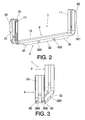
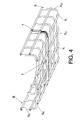
- the connecting piece which has been generally designated by means of the numerical reference 1, has been foreseen to couple two cable channelling sections B, B that are adjacent lengthwise, as it can be clearly appreciated in figure 4 .
- the connecting piece 1 has a front part 2 and a rear part 3 which is used for the snap-on fitting of the cross wire bars Vt1-Vt2 of the ends of two channel sections.
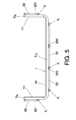
- the rear part 3 of the connecting piece 1 has a cross-section with a W-shape, which has, on the one hand, two respective longitudinal grooves 30 with a C-shaped cross-section, where the mentioned wire bars are fitted, and a central portion 31 which extends connecting the respective longitudinal grooves; and on the other hand, corresponding flanges 32 that extend from the outer edges of the respective longitudinal grooves 30 to be overlapped at the outer edge of the said cross wire bars Vt1, Vt2 of the corresponding channellling section B.
- the connecting piece 1 is generally configured in the shape of an U with a central branch 10 which extends practically covering the whole length of the relevant central branch Vt1 of the cross bars, and the respective side branches 11 that extend forming an angle with the central branch 10 that is equal to or greater than the angle formed by the two side branches Vt2 and the central branch Vt1 of the cross bars of the cable channelling. Furthermore, each one of the side branches 11 extends covering, either fully or partially, the corresponding side branch Vt2 of the cross bars.
- the flange 32 corresponding to the central branch 10 of the connecting piece 1 can be optionally provided with notches 320 through which the longitudinal wire bars V1 of the cable channelling sections B may run.
- the flanges 32 corresponding to the side branches 11 of the said connecting piece 1 have an extension that corresponds to the cross distance between every two other adjacent longitudinal wire bars V1, the said flanges being provided with a bevel edge 321 inclined downwards, which serves to retain such longitudinal wire bars.
- the connection with the connection piece only demands a modest effort to be dismounted; however, once the sections have been connected, they cannot be dismounted as a result of the vertical forces exercised in an upwards direction.
Landscapes
- Engineering & Computer Science (AREA)
- Architecture (AREA)
- Civil Engineering (AREA)
- Structural Engineering (AREA)
- Details Of Indoor Wiring (AREA)
- Supports For Pipes And Cables (AREA)
- Laying Of Electric Cables Or Lines Outside (AREA)
- Installation Of Indoor Wiring (AREA)
Applications Claiming Priority (1)
| Application Number | Priority Date | Filing Date | Title |
|---|---|---|---|
| PCT/ES2012/070068 WO2013113953A1 (es) | 2012-02-02 | 2012-02-02 | Pieza de unión de tramos de canalizaciones para cables de rejilla |
Publications (2)
| Publication Number | Publication Date |
|---|---|
| EP2811595A1 true EP2811595A1 (de) | 2014-12-10 |
| EP2811595B1 EP2811595B1 (de) | 2015-12-16 |
Family
ID=45976959
Family Applications (1)
| Application Number | Title | Priority Date | Filing Date |
|---|---|---|---|
| EP12715410.2A Active EP2811595B1 (de) | 2012-02-02 | 2012-02-02 | Verbindungselement für gitterkabelrinnen |
Country Status (5)
| Country | Link |
|---|---|
| EP (1) | EP2811595B1 (de) |
| ES (1) | ES2558561T3 (de) |
| MA (1) | MA35646B1 (de) |
| PT (1) | PT2811595E (de) |
| WO (1) | WO2013113953A1 (de) |
Cited By (1)
| Publication number | Priority date | Publication date | Assignee | Title |
|---|---|---|---|---|
| FR3080227A1 (fr) * | 2018-04-11 | 2019-10-18 | Gewiss France Sas | Systeme de chemin de cables et methode de fixation d'une eclisse sur un troncon de chemin de cables en treillis |
Families Citing this family (2)
| Publication number | Priority date | Publication date | Assignee | Title |
|---|---|---|---|---|
| FR3014607B1 (fr) * | 2013-12-11 | 2016-01-08 | Niedax France | Eclisse monobloc pour chemin de cables en treillis de fil, munie de languettes de maintien |
| US11662041B2 (en) | 2019-07-29 | 2023-05-30 | Erico International Corporation | Support clip |
Family Cites Families (5)
| Publication number | Priority date | Publication date | Assignee | Title |
|---|---|---|---|---|
| FR2652206B1 (fr) | 1989-09-15 | 1991-12-06 | Krieg & Zivy | Eclisse rapide pour chemin de cable en fils soudes. |
| DE19831145C1 (de) | 1998-07-11 | 1999-11-11 | Bettermann Obo Gmbh & Co Kg | Gitterkabelrinne |
| DE202007009658U1 (de) * | 2007-07-11 | 2007-09-06 | Niedax Gmbh & Co. Kg | Gitterrinne sowie Gitterrinnenverbindung |
| ES2370570B1 (es) | 2009-06-04 | 2012-11-02 | Aiscan, S.L | Sistema de grapado para union de tramos de canal para cables de rejilla |
| ES2388519B1 (es) * | 2010-01-15 | 2013-12-16 | Aiscan S.L. | Sistema de grapado para unión de tramos de canal para cables de rejilla, mejorado |
-
2012
- 2012-02-02 PT PT127154102T patent/PT2811595E/pt unknown
- 2012-02-02 ES ES12715410.2T patent/ES2558561T3/es active Active
- 2012-02-02 WO PCT/ES2012/070068 patent/WO2013113953A1/es not_active Ceased
- 2012-02-02 EP EP12715410.2A patent/EP2811595B1/de active Active
-
2014
- 2014-05-14 MA MA37029A patent/MA35646B1/fr unknown
Non-Patent Citations (1)
| Title |
|---|
| See references of WO2013113953A1 * |
Cited By (1)
| Publication number | Priority date | Publication date | Assignee | Title |
|---|---|---|---|---|
| FR3080227A1 (fr) * | 2018-04-11 | 2019-10-18 | Gewiss France Sas | Systeme de chemin de cables et methode de fixation d'une eclisse sur un troncon de chemin de cables en treillis |
Also Published As
| Publication number | Publication date |
|---|---|
| WO2013113953A1 (es) | 2013-08-08 |
| PT2811595E (pt) | 2016-02-04 |
| EP2811595B1 (de) | 2015-12-16 |
| ES2558561T3 (es) | 2016-02-05 |
| MA35646B1 (fr) | 2014-11-01 |
Similar Documents
| Publication | Publication Date | Title |
|---|---|---|
| US20150041742A1 (en) | Fence column and fence system having the fence column | |
| EP1978288B1 (de) | Rohrklemme mit Schnellverschluss | |
| KR101726156B1 (ko) | 케이블 트레이의 연결구조 | |
| EP2811595B1 (de) | Verbindungselement für gitterkabelrinnen | |
| CN102562730A (zh) | 紧固件 | |
| EP3237777B1 (de) | Verbesserungen an oder im zusammenhang mit klemmvorrichtungen | |
| JP6269309B2 (ja) | 雌端子 | |
| EP3945648B1 (de) | Kabelklemmenanordnung mit niedrigem profil | |
| US20180216753A1 (en) | Plastic cable management design for retaining wire bundles in aerospace applications | |
| GB2485071A (en) | Coupleable wire mesh cable tray | |
| KR101649449B1 (ko) | 강화버팀보를 이용한 이음장치 | |
| EP2346129B1 (de) | Spannsystem zur Verbindung von Drahtgitterkabelkanalabschnitte | |
| CN109038434B (zh) | 一种楔形直通耐张线夹 | |
| EP2704277B1 (de) | Verbessertes verbindungsstück für segmente von korbführungen für kabel | |
| RU2754690C1 (ru) | Устройство для усиления существующей конструкции и устройство для крепления дополнительного оборудования | |
| EP2754901A2 (de) | Trampolinrahmenrohrverbinder zum Verbinden von zwei Rahmenrohrteilen eines Trampolins | |
| CN107017516A (zh) | 连接器 | |
| KR20210000863U (ko) | 철근 연결용 나사식 원터치 커플러 | |
| EP1746697A1 (de) | Befestigungselement zum Befestigen einer Dose an einen Drahtgitterkanal | |
| KR200441762Y1 (ko) | 비닐하우스용 파이프 연결장치 | |
| KR101845055B1 (ko) | 케이블 타이 조임장치 | |
| KR101351977B1 (ko) | 비닐하우스용 파이프 체결구 | |
| KR100750806B1 (ko) | 방범창 | |
| KR20110011998U (ko) | 배수로용 그레이팅 연결구조 | |
| KR200465515Y1 (ko) | 파이프고정용 이중 클램프 |
Legal Events
| Date | Code | Title | Description |
|---|---|---|---|
| PUAI | Public reference made under article 153(3) epc to a published international application that has entered the european phase |
Free format text: ORIGINAL CODE: 0009012 |
|
| 17P | Request for examination filed |
Effective date: 20140718 |
|
| AK | Designated contracting states |
Kind code of ref document: A1 Designated state(s): AL AT BE BG CH CY CZ DE DK EE ES FI FR GB GR HR HU IE IS IT LI LT LU LV MC MK MT NL NO PL PT RO RS SE SI SK SM TR |
|
| AX | Request for extension of the european patent |
Extension state: BA ME |
|
| DAX | Request for extension of the european patent (deleted) | ||
| GRAP | Despatch of communication of intention to grant a patent |
Free format text: ORIGINAL CODE: EPIDOSNIGR1 |
|
| INTG | Intention to grant announced |
Effective date: 20150911 |
|
| GRAS | Grant fee paid |
Free format text: ORIGINAL CODE: EPIDOSNIGR3 |
|
| GRAA | (expected) grant |
Free format text: ORIGINAL CODE: 0009210 |
|
| AK | Designated contracting states |
Kind code of ref document: B1 Designated state(s): AL AT BE BG CH CY CZ DE DK EE ES FI FR GB GR HR HU IE IS IT LI LT LU LV MC MK MT NL NO PL PT RO RS SE SI SK SM TR |
|
| REG | Reference to a national code |
Ref country code: GB Ref legal event code: FG4D |
|
| REG | Reference to a national code |
Ref country code: CH Ref legal event code: EP |
|
| REG | Reference to a national code |
Ref country code: IE Ref legal event code: FG4D |
|
| REG | Reference to a national code |
Ref country code: AT Ref legal event code: REF Ref document number: 765971 Country of ref document: AT Kind code of ref document: T Effective date: 20160115 |
|
| REG | Reference to a national code |
Ref country code: DE Ref legal event code: R096 Ref document number: 602012013115 Country of ref document: DE |
|
| REG | Reference to a national code |
Ref country code: PT Ref legal event code: SC4A Free format text: AVAILABILITY OF NATIONAL TRANSLATION Effective date: 20160105 |
|
| REG | Reference to a national code |
Ref country code: ES Ref legal event code: FG2A Ref document number: 2558561 Country of ref document: ES Kind code of ref document: T3 Effective date: 20160205 |
|
| REG | Reference to a national code |
Ref country code: FR Ref legal event code: PLFP Year of fee payment: 5 |
|
| REG | Reference to a national code |
Ref country code: NL Ref legal event code: MP Effective date: 20151216 |
|
| REG | Reference to a national code |
Ref country code: LT Ref legal event code: MG4D |
|
| PG25 | Lapsed in a contracting state [announced via postgrant information from national office to epo] |
Ref country code: LT Free format text: LAPSE BECAUSE OF FAILURE TO SUBMIT A TRANSLATION OF THE DESCRIPTION OR TO PAY THE FEE WITHIN THE PRESCRIBED TIME-LIMIT Effective date: 20151216 Ref country code: HR Free format text: LAPSE BECAUSE OF FAILURE TO SUBMIT A TRANSLATION OF THE DESCRIPTION OR TO PAY THE FEE WITHIN THE PRESCRIBED TIME-LIMIT Effective date: 20151216 Ref country code: NO Free format text: LAPSE BECAUSE OF FAILURE TO SUBMIT A TRANSLATION OF THE DESCRIPTION OR TO PAY THE FEE WITHIN THE PRESCRIBED TIME-LIMIT Effective date: 20160316 |
|
| REG | Reference to a national code |
Ref country code: AT Ref legal event code: MK05 Ref document number: 765971 Country of ref document: AT Kind code of ref document: T Effective date: 20151216 |
|
| PG25 | Lapsed in a contracting state [announced via postgrant information from national office to epo] |
Ref country code: RS Free format text: LAPSE BECAUSE OF FAILURE TO SUBMIT A TRANSLATION OF THE DESCRIPTION OR TO PAY THE FEE WITHIN THE PRESCRIBED TIME-LIMIT Effective date: 20151216 Ref country code: GR Free format text: LAPSE BECAUSE OF FAILURE TO SUBMIT A TRANSLATION OF THE DESCRIPTION OR TO PAY THE FEE WITHIN THE PRESCRIBED TIME-LIMIT Effective date: 20160317 Ref country code: BE Free format text: LAPSE BECAUSE OF NON-PAYMENT OF DUE FEES Effective date: 20160229 Ref country code: SE Free format text: LAPSE BECAUSE OF FAILURE TO SUBMIT A TRANSLATION OF THE DESCRIPTION OR TO PAY THE FEE WITHIN THE PRESCRIBED TIME-LIMIT Effective date: 20151216 Ref country code: LV Free format text: LAPSE BECAUSE OF FAILURE TO SUBMIT A TRANSLATION OF THE DESCRIPTION OR TO PAY THE FEE WITHIN THE PRESCRIBED TIME-LIMIT Effective date: 20151216 Ref country code: FI Free format text: LAPSE BECAUSE OF FAILURE TO SUBMIT A TRANSLATION OF THE DESCRIPTION OR TO PAY THE FEE WITHIN THE PRESCRIBED TIME-LIMIT Effective date: 20151216 Ref country code: NL Free format text: LAPSE BECAUSE OF FAILURE TO SUBMIT A TRANSLATION OF THE DESCRIPTION OR TO PAY THE FEE WITHIN THE PRESCRIBED TIME-LIMIT Effective date: 20151216 |
|
| PG25 | Lapsed in a contracting state [announced via postgrant information from national office to epo] |
Ref country code: IT Free format text: LAPSE BECAUSE OF FAILURE TO SUBMIT A TRANSLATION OF THE DESCRIPTION OR TO PAY THE FEE WITHIN THE PRESCRIBED TIME-LIMIT Effective date: 20151216 Ref country code: CZ Free format text: LAPSE BECAUSE OF FAILURE TO SUBMIT A TRANSLATION OF THE DESCRIPTION OR TO PAY THE FEE WITHIN THE PRESCRIBED TIME-LIMIT Effective date: 20151216 |
|
| PG25 | Lapsed in a contracting state [announced via postgrant information from national office to epo] |
Ref country code: IS Free format text: LAPSE BECAUSE OF FAILURE TO SUBMIT A TRANSLATION OF THE DESCRIPTION OR TO PAY THE FEE WITHIN THE PRESCRIBED TIME-LIMIT Effective date: 20160416 Ref country code: SK Free format text: LAPSE BECAUSE OF FAILURE TO SUBMIT A TRANSLATION OF THE DESCRIPTION OR TO PAY THE FEE WITHIN THE PRESCRIBED TIME-LIMIT Effective date: 20151216 Ref country code: AT Free format text: LAPSE BECAUSE OF FAILURE TO SUBMIT A TRANSLATION OF THE DESCRIPTION OR TO PAY THE FEE WITHIN THE PRESCRIBED TIME-LIMIT Effective date: 20151216 Ref country code: SM Free format text: LAPSE BECAUSE OF FAILURE TO SUBMIT A TRANSLATION OF THE DESCRIPTION OR TO PAY THE FEE WITHIN THE PRESCRIBED TIME-LIMIT Effective date: 20151216 Ref country code: RO Free format text: LAPSE BECAUSE OF FAILURE TO SUBMIT A TRANSLATION OF THE DESCRIPTION OR TO PAY THE FEE WITHIN THE PRESCRIBED TIME-LIMIT Effective date: 20151216 Ref country code: EE Free format text: LAPSE BECAUSE OF FAILURE TO SUBMIT A TRANSLATION OF THE DESCRIPTION OR TO PAY THE FEE WITHIN THE PRESCRIBED TIME-LIMIT Effective date: 20151216 |
|
| REG | Reference to a national code |
Ref country code: DE Ref legal event code: R097 Ref document number: 602012013115 Country of ref document: DE |
|
| PG25 | Lapsed in a contracting state [announced via postgrant information from national office to epo] |
Ref country code: LU Free format text: LAPSE BECAUSE OF FAILURE TO SUBMIT A TRANSLATION OF THE DESCRIPTION OR TO PAY THE FEE WITHIN THE PRESCRIBED TIME-LIMIT Effective date: 20160202 Ref country code: MC Free format text: LAPSE BECAUSE OF FAILURE TO SUBMIT A TRANSLATION OF THE DESCRIPTION OR TO PAY THE FEE WITHIN THE PRESCRIBED TIME-LIMIT Effective date: 20151216 |
|
| REG | Reference to a national code |
Ref country code: CH Ref legal event code: PL |
|
| PLBE | No opposition filed within time limit |
Free format text: ORIGINAL CODE: 0009261 |
|
| STAA | Information on the status of an ep patent application or granted ep patent |
Free format text: STATUS: NO OPPOSITION FILED WITHIN TIME LIMIT |
|
| PG25 | Lapsed in a contracting state [announced via postgrant information from national office to epo] |
Ref country code: DK Free format text: LAPSE BECAUSE OF FAILURE TO SUBMIT A TRANSLATION OF THE DESCRIPTION OR TO PAY THE FEE WITHIN THE PRESCRIBED TIME-LIMIT Effective date: 20151216 Ref country code: LI Free format text: LAPSE BECAUSE OF NON-PAYMENT OF DUE FEES Effective date: 20160229 Ref country code: PL Free format text: LAPSE BECAUSE OF FAILURE TO SUBMIT A TRANSLATION OF THE DESCRIPTION OR TO PAY THE FEE WITHIN THE PRESCRIBED TIME-LIMIT Effective date: 20151216 Ref country code: CH Free format text: LAPSE BECAUSE OF NON-PAYMENT OF DUE FEES Effective date: 20160229 |
|
| 26N | No opposition filed |
Effective date: 20160919 |
|
| REG | Reference to a national code |
Ref country code: IE Ref legal event code: MM4A |
|
| PG25 | Lapsed in a contracting state [announced via postgrant information from national office to epo] |
Ref country code: BE Free format text: LAPSE BECAUSE OF FAILURE TO SUBMIT A TRANSLATION OF THE DESCRIPTION OR TO PAY THE FEE WITHIN THE PRESCRIBED TIME-LIMIT Effective date: 20151216 |
|
| PG25 | Lapsed in a contracting state [announced via postgrant information from national office to epo] |
Ref country code: IE Free format text: LAPSE BECAUSE OF NON-PAYMENT OF DUE FEES Effective date: 20160202 |
|
| REG | Reference to a national code |
Ref country code: FR Ref legal event code: PLFP Year of fee payment: 6 |
|
| PG25 | Lapsed in a contracting state [announced via postgrant information from national office to epo] |
Ref country code: SI Free format text: LAPSE BECAUSE OF FAILURE TO SUBMIT A TRANSLATION OF THE DESCRIPTION OR TO PAY THE FEE WITHIN THE PRESCRIBED TIME-LIMIT Effective date: 20151216 |
|
| PG25 | Lapsed in a contracting state [announced via postgrant information from national office to epo] |
Ref country code: MT Free format text: LAPSE BECAUSE OF FAILURE TO SUBMIT A TRANSLATION OF THE DESCRIPTION OR TO PAY THE FEE WITHIN THE PRESCRIBED TIME-LIMIT Effective date: 20151216 |
|
| REG | Reference to a national code |
Ref country code: FR Ref legal event code: PLFP Year of fee payment: 7 |
|
| PG25 | Lapsed in a contracting state [announced via postgrant information from national office to epo] |
Ref country code: HU Free format text: LAPSE BECAUSE OF FAILURE TO SUBMIT A TRANSLATION OF THE DESCRIPTION OR TO PAY THE FEE WITHIN THE PRESCRIBED TIME-LIMIT; INVALID AB INITIO Effective date: 20120202 |
|
| PG25 | Lapsed in a contracting state [announced via postgrant information from national office to epo] |
Ref country code: CY Free format text: LAPSE BECAUSE OF FAILURE TO SUBMIT A TRANSLATION OF THE DESCRIPTION OR TO PAY THE FEE WITHIN THE PRESCRIBED TIME-LIMIT Effective date: 20151216 Ref country code: MT Free format text: LAPSE BECAUSE OF FAILURE TO SUBMIT A TRANSLATION OF THE DESCRIPTION OR TO PAY THE FEE WITHIN THE PRESCRIBED TIME-LIMIT Effective date: 20160229 Ref country code: MK Free format text: LAPSE BECAUSE OF FAILURE TO SUBMIT A TRANSLATION OF THE DESCRIPTION OR TO PAY THE FEE WITHIN THE PRESCRIBED TIME-LIMIT Effective date: 20151216 |
|
| PG25 | Lapsed in a contracting state [announced via postgrant information from national office to epo] |
Ref country code: BG Free format text: LAPSE BECAUSE OF FAILURE TO SUBMIT A TRANSLATION OF THE DESCRIPTION OR TO PAY THE FEE WITHIN THE PRESCRIBED TIME-LIMIT Effective date: 20151216 |
|
| PG25 | Lapsed in a contracting state [announced via postgrant information from national office to epo] |
Ref country code: AL Free format text: LAPSE BECAUSE OF FAILURE TO SUBMIT A TRANSLATION OF THE DESCRIPTION OR TO PAY THE FEE WITHIN THE PRESCRIBED TIME-LIMIT Effective date: 20151216 Ref country code: TR Free format text: LAPSE BECAUSE OF FAILURE TO SUBMIT A TRANSLATION OF THE DESCRIPTION OR TO PAY THE FEE WITHIN THE PRESCRIBED TIME-LIMIT Effective date: 20151216 |
|
| PGFP | Annual fee paid to national office [announced via postgrant information from national office to epo] |
Ref country code: DE Payment date: 20230227 Year of fee payment: 12 |
|
| REG | Reference to a national code |
Ref country code: DE Ref legal event code: R119 Ref document number: 602012013115 Country of ref document: DE |
|
| PG25 | Lapsed in a contracting state [announced via postgrant information from national office to epo] |
Ref country code: DE Free format text: LAPSE BECAUSE OF NON-PAYMENT OF DUE FEES Effective date: 20240903 |
|
| PG25 | Lapsed in a contracting state [announced via postgrant information from national office to epo] |
Ref country code: DE Free format text: LAPSE BECAUSE OF NON-PAYMENT OF DUE FEES Effective date: 20240903 |
|
| PGFP | Annual fee paid to national office [announced via postgrant information from national office to epo] |
Ref country code: GB Payment date: 20260115 Year of fee payment: 15 |
|
| PGFP | Annual fee paid to national office [announced via postgrant information from national office to epo] |
Ref country code: ES Payment date: 20260305 Year of fee payment: 15 |
|
| PGFP | Annual fee paid to national office [announced via postgrant information from national office to epo] |
Ref country code: FR Payment date: 20260115 Year of fee payment: 15 |
|
| PGFP | Annual fee paid to national office [announced via postgrant information from national office to epo] |
Ref country code: PT Payment date: 20260120 Year of fee payment: 15 |