EP2811658B1 - Flugzeugdatenübertragung mithilfe von Phasentrennung - Google Patents
Flugzeugdatenübertragung mithilfe von Phasentrennung Download PDFInfo
- Publication number
- EP2811658B1 EP2811658B1 EP14168710.3A EP14168710A EP2811658B1 EP 2811658 B1 EP2811658 B1 EP 2811658B1 EP 14168710 A EP14168710 A EP 14168710A EP 2811658 B1 EP2811658 B1 EP 2811658B1
- Authority
- EP
- European Patent Office
- Prior art keywords
- data
- bpl
- transmission
- communication channel
- aircraft
- Prior art date
- Legal status (The legal status is an assumption and is not a legal conclusion. Google has not performed a legal analysis and makes no representation as to the accuracy of the status listed.)
- Active
Links
Images


Classifications
-
- H—ELECTRICITY
- H04—ELECTRIC COMMUNICATION TECHNIQUE
- H04B—TRANSMISSION
- H04B3/00—Line transmission systems
- H04B3/54—Systems for transmission via power distribution lines
-
- H—ELECTRICITY
- H04—ELECTRIC COMMUNICATION TECHNIQUE
- H04B—TRANSMISSION
- H04B2203/00—Indexing scheme relating to line transmission systems
- H04B2203/54—Aspects of powerline communications not already covered by H04B3/54 and its subgroups
- H04B2203/5404—Methods of transmitting or receiving signals via power distribution lines
- H04B2203/5408—Methods of transmitting or receiving signals via power distribution lines using protocols
-
- H—ELECTRICITY
- H04—ELECTRIC COMMUNICATION TECHNIQUE
- H04B—TRANSMISSION
- H04B2203/00—Indexing scheme relating to line transmission systems
- H04B2203/54—Aspects of powerline communications not already covered by H04B3/54 and its subgroups
- H04B2203/5462—Systems for power line communications
- H04B2203/5466—Systems for power line communications using three phases conductors
Definitions
- the amount of software and data stored in and collected by onboard aircraft information systems is growing at a rapid pace.
- the onboard information systems use software and data for various cabin systems, avionics systems, and entertainment systems, among other things. Data may also be generated by some of these systems during operations of the aircraft.
- Airlines are typically responsible for updating the data and software on their aircrafts and timely downloading certain data collected during flights. All these activities require fast and secure data transfers between aircrafts and external networks while the aircrafts are on the ground, e.g., parked at the gates. While such data transfers may be performed over a variety of airport and other networks, availability and costs of using these networks may be very limiting.
- US2013/0003756 discloses a method for providing information to a vehicle over a three-phase power line by optimizing the data rate of transmission through the control of frequency modulation.
- US2005/0143868 discloses a method for providing broadband data services to moving vehicles over power lines by connecting the vehicle to a transport power line.
- a channel management unit is used to control matching different data domains with different communication channels depending on, for example, characteristics of the data domains, characteristics of the channels, and other factors.
- one channel may be designated for secure data transfer of specific data domains, such as aircraft control data.
- the channel management unit generates the first transmission packet and the second transmission packet based on one or more factors, such as duration of the power cable connection, security status of each of the multiple data domains, security of each of the first BPL communication channel and the second BPL communication channel, transmission priority of each of the multiple data domains, transmission rate of each of the first BPL communication channel and the second BPL communication channel, and data amount in each of the multiple data domains.
- a method for terrestrial data transmission between aircrafts and external networks involves two BPL communication channels through an electrical power cable connected to an aircraft and a gate.
- the power cable includes two conductors: a first conductor and a second conductor.
- the first BPL communication channel is established through the first conductor and uses a first frequency band
- the second BPL communication channel is established through the second conductor and uses a second frequency band.
- the second frequency band does not overlap with the first frequency band.
- the method also involves generating a first transmission packet and a second transmission packet from multiple data domains using a channel management unit.
- the channel management unit may generate these transmission packets before, during, or after establishing the BPL communication channels.
- the method proceeds with sending the first transmission packet for transmission through the first BPL communication channel and the second transmission packet for transmission through the second BPL communication channel.
- transmission of the first transmission packet and the second transmission packet is performed at the same time. More generally, transmission of the first transmission packet is performed independently from transmission of the second transmission packet. The transmission of the packets may be performed based on availability and performance of the BPL communication channels.
- the multiple data domains may include aircraft control data, in-flight entertainment, and/or airplane information system.
- the method may involve prefetching at least some of the multiple data domains to the gate. This feature may expedite transmission of the packets from the gate to the aircraft.
- the first transmission packet is generated from only one of the multiple domains.
- the first transmission packet may include only one of the following types of data: aircraft control data, in-flight entertainment, and/or airplane information system.
- the first transmission packet is generated from two or more of the multiple domains.
- the first transmission packet may include a combination of aircraft control data and airplane information system.
- the method also involves generating one or more additional transmission packets for transmitting over the first BPL communication channel. These additional transmission packets may be different from the first transmission packets.
- the channel management unit may select an order to sending the first and additional transmission packets through the first BPL communication channel.
- the method also involves checking time availability for transmission over the first BPL communication channel and the second BPL communication channel.
- the channel management unit may be determining the size of each transmission packet and the transmission rate of each channel to determine the time needed to transmit each pack. This time may be compared with the remaining time of the connection between the gate and the aircraft using the electrical power cable.
- the first frequency band is below 30 MHz, while at least a portion of the second frequency band is above 30 MHz.
- the first frequency range does not overlap with the second frequency range.
- the first frequency range may be between 2 MHz and 28 MHz, while the second frequency range may be between 28 MHz and 60 MHz.
- the method also involves establishing a third BPL communication channel through a third conductor of the electrical power cable.
- the third BPL communication channel uses a third frequency band that does not overlap with the first frequency band and the second frequency band.
- the method also involves generating a third transmission packet from multiple data domains using the channel management unit and sending the third transmission packet through the third BPL communication channel.
- at least a portion of the first frequency band is below 30 Mhz
- at least a portion of the second frequency band is between 30 Mhz and 67 Mhz
- at least a portion of the third frequency band is above 67 Mhz.
- each of the first conductor and the second conductor is configured to transmit an electrical current of at least about 50 Amps per phase.
- the electrical power cable may not include a radio frequency (RF) shielding around the first conductor or the second conductor.
- RF radio frequency
- the electrical power cable is between about 10 feet and 500 feet long.
- the method may also involve transmitting electrical power at about 110V and about 400Hz using the first conductor while sending the first transmission packet through the first BPL communication channel.
- the system includes an electrical power connector for connecting to an electrical power cable.
- the system also includes the electrical power connector comprising a first conductor and a second conductor.
- Other components of the system are a first BPL module and a second BPL module.
- the first BPL module is coupled to the first conductor and configured to establish a first BPL communication channel using a first frequency band.
- the second BPL module is coupled to the second conductor and configured to establish a second BPL communication channel using a second frequency band.
- the second frequency band does not overlap with the first frequency band.
- the system also includes a channel management unit coupled to the first BPL module and to the second BPL module.
- the channel management unit is configured to generate a first transmission packet and a second transmission packet from multiple data domains.
- the channel management unit is also configured to send the first transmission packet through the first BPL communication channel and the second transmission packet through the second BPL communication channel.
- the channel management unit generates the first transmission packet and the second transmission packet based on one or more factors, such as duration of the power cable connection, security status of each of the multiple data domains, security of each of the first BPL communication channel and the second BPL communication channel, transmission priority of each of the multiple data domains, transmission rate of each of the first BPL communication channel and the second BPL communication channel, and data amount in each of the multiple data domains.
- the system also includes a first computer system configured to store a first data domain of the multiple data domains and a second computer system configured to store a second data domain of the multiple data domains.
- the first computer system and the second computer system are communicatively coupled to the channel management system.
- the multiple data domains may include one or more data types, such as aircraft control data, in-flight entertainment, and airplane information system.
- data domains are identified by standardized initiatives, such as Federal Aviation Administration (FAA) NextGen Initiative in the United States and/or Single European Sky ATM Research (SESAR) in Europe.
- FAA Federal Aviation Administration
- SESAR Single European Sky ATM Research
- a computer program product including a computer usable medium having a computer readable program code embodied therein.
- the computer readable program code adapted to be executed to implement a method for terrestrial data transmission between aircrafts and external networks as described in this document.
- Wi-Fi and cellular technologies have been proposed for these purposes to replace traditional paper based systems and manual transfer of data carriers. Some of these technologies have been partially adopted by various airports and airlines. However, these technologies are often inconsistent or even unavailable due to technical, business, and regulatory complexities of the airline industry.
- a standard electrical power cable often referred to as a stinger cable, is used for many types of commercial aircrafts, such as Boeing 707 through Boeing 787 and Airbus 300 through A380.
- This electrical power cable may be used to supply electrical power using an alternating current (AC) at 110V and 400 Hz.
- the cable may have three conductors to support three phases of the electrical current, a ground conductor, and a number of control conductors.
- AC alternating current
- other types of cables used in the airline industry for making connections to aircrafts are also within the scope.
- an electrical power cable may include six different conductors, such as three conductors for three phase power transmission, a neutral/ground conductor, and two control conductors.
- BPL communication channels may be established between the aircraft and the gate providing various options for data transfer.
- three phase conductors may be used for establishing three different BPL communication channels.
- One of the channels may be designated for high security data only; another channel, for medium security data that needs to be transferred fast; and yet another channel, for all other channels.
- a channel management unit may be used to control allocation of BPL communication channels, for example, by generating transmission packs for each specific channel. The transmission packs may be generated by the channel management unit from data domains available for transfer.
- one or more communication channels may be dedicated to a particular data domain or a set of multiple data domains having common characteristics. For example, all high security data may be transmitted through the same channel. This channel may not be used for transmission of any other types of data, for example, regardless its availability.
- a communication channel is shared by multiple different domains. Matching of data domains and communication channels may be performed dynamically, such as using periodic updates. For example, the channel management unit may periodically check availability of the channels, transmission rates of the channels, security of the channel, and other characteristics to determine which channels to use for transfer of certain data domains.
- a data domain may be parsed for transmission and used to generate multiple transmission packets from the same domain. These packets may be then sent using the same communication channel or multiple different communication channels.
- the channel management unit may use information about the data domains, communication channels, and environment to form multiple transmission packets from the data domains and sending each transmission packet through its designated communication channel.
- Each communication channel may be formed by two BPL modules coupled to the same conductor using either inductive or capacitive coupling.
- One of the BPL modules is positioned on the aircraft and may be referred to as an aircraft BPL module, while another BPL module is positioned at the gate and may be referred to as a gate BPL module.
- a BPL modem may function as one or more BPL modules.
- a single aircraft BPL modem may be capable of establishing multiple communication channels with gate BPL modules.
- the gate BPL modules may be also integrated into the same modem, but this integration is not necessary and separate BPL modules may be used at the gate.
- Various BPL protocols such as IEEE1901 / ITU-TG.hn, may be used for BPL communication channel.
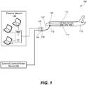
- FIG. 1 is a schematic illustration of a system 100 for terrestrial data transmission between an aircraft 110 and an external network 130 through gate 120, in accordance with some embodiments. While only one external network 130 is illustrated in this figure, one having ordinary skills in the art would understand that any number of external networks can be connected to gate 120 and exchange data with aircraft 110.
- Aircraft 110 is parked at gate 120 and connected to gate 120 using an electrical power cable 122.
- Aircraft 110 and, in some embodiments, gate 120 may be equipped with electrical power connectors for making these connections to electrical power cable 122.
- Electrical power cable 122 may be a standardized power cable suitable for different types of aircrafts, such as a stinger cable.
- the stinger cable is an insulated, flexible, all weather extension cord used to supply 3 phase, 400 Hz, 115 VAC electrical power.
- Electrical power cable 122 is capable of transmitting an electrical current of at least about 50A in each phase. Electrical power cable 122 may be between about 10 feet and 500 feet long and nearly 2 inches in diameter. Additional details of electrical power cable 122 are described below with reference to FIG. 3A .
- electrical power cable 122 includes two or more conductors.
- the electrical power to gate 120 may be supplied by external electrical power supply 150 that may include frequency converters, transformers, and other like electrical power equipment. It should be noted that data signals transmitted through electrical power cable 122 are not generally transmitted beyond external electrical power supply 150. In some embodiments, the data signals are not transmitted beyond gate 120.
- gate 120 and power supply 150 may be provided in the same location and may even be combined into the same physical unit.
- Aircraft 110 may be equipped with a set of aircraft BPL modules 112 and an aircraft channel management unit 116.
- multiple aircraft BPL modules 112 are coupled to the same aircraft channel management unit 116, which is in turn connected to one or more computer systems 115 of aircraft 110.
- Each of aircraft BPL modules 112 is connected to a separate conductor of electrical power cable 122 as further described below with reference to FIG. 2 .
- Gate 120 also includes multiple BPL modules 124, which may be referred to as gate BPL modules.
- the gate is defined as a structure to which electrical power cable 122 is connected to.
- a gate may include additional components disposed away from the parking location of aircraft 110.
- gate 120 may include a solid state frequency converter, which may be positioned near the parking location of aircraft 110 or away from this location, such as inside the airport facility.
- gate BPL modules 124 may be positioned near the parking location of aircraft 110 or away from this location.
- Gate BPL modules 124 may be connected to one or more external networks 130.
- gate 120 may include various communication modules, such as an Ethernet module, a Wi-Fi module, and/or a cellular module for connecting to external networks 130.
- Aircraft BPL modules 112 and gate BPL modules 124 are configured to establish multiple communication channels between aircraft 110 and gate 120. Specifically, a pair including one aircraft BPL module and one gate BPL module connected to the same conductor of electrical power cable 122 establishes a BPL communication link. Various transmission domains available on aircraft 110, gate 120, and/or external network 130 may be transmitted through these BPL communication channels while electrical power cable 122 is connected to both aircraft 110 and gate 120. Data transmission and power transmission may be performed at the same time using the same conductor. Data and power are transmitted using different frequency bands (e.g., 400 Hz for power and 2-80 MHz for data), which minimizes interference between these two transmissions. Furthermore, each BPL communication channel operates using its own frequency band that is different from frequency bands of any other channels.
- each BPL communication channel operates using its own frequency band that is different from frequency bands of any other channels.
- the BPL communication channels may be configured to provide secure data transfer in comparison to other types of communication links that are currently available in the airport environment. Specifically, data signals transferred through the BPL communication channels are restricted to electrical power cable 122 and a few other electrical power components that operate at a certain frequency, for example, 400 Hz. All of these electrical power components are typically located within airport areas having restricted access. The data signals will be blocked by frequency converters, transformers, and other such electrical power components. The data signal is effectively contained within a small portion of the overall power system that is connected to an aircraft. Security within BPL communication channels may be further enhanced by encryption and other like technologies.
- gate BPL module 124 may be physically restricted.
- secure enclosures that require successful authentication, via credentials, multi-factor crew authentication, digital keys, passcodes, RFID, biometrics, etc., to gain physical access to these modules and cables may be used.
- gate BPL modules 124 and/or cable 122 may include GPS receivers for verifying that gate BPL modules 124 and/or cable 122 have not been moved from a pre-determined position.
- gate BPL modules 124 may be configured with a secure routing table that facilitates routing information via external network 130 using pre-determined hops and/or pre-determined destinations.
- Gate BPL modules 124 may be identified and/or addressed by a hardware identifier such as a MAC address.
- gate BPL modules 124 may include various computer system components, such as output devices and ports (e.g., a display), input devices (e.g., a keyboard, touch screen, mouse), a memory (e.g., tangible computer readable memory).
- gate BPL modules 124 may include a channel management unit 126 for generating transmission packets and sending these transmission packets through established BPL communication channels.
- Various servers may be a part of or connected to external network 130, such as airline servers, airport servers, aircraft service provider servers, aircraft manufacturer servers, and the like. These servers may be connected to external network 130 via a LAN, WAN, and/or the Internet. These servers may be configured to provide and receive data to and from aircraft 110. For example, the servers may provide software and/or firmware updates to components of aircraft 110, such as cabin systems software, flight bag, and avionics software. The servers may also provide content, such as music and movies, for in-flight entertainment systems on aircraft 110. External network 130 may also provide communication between aircraft 110.
- BPL communication channels may be created by impressing a modulated carrier signal on a portion of the electrical power system extending between aircraft 110 and gate 130 and including electrical power cable 122.
- Gate BPL modules 124 and aircraft BPL modules 112 are used for impressing such signals on individual conductors of electrical power cable 122 when transmitting data. The same modules are also used for extracting data from these signals when receiving data.
- Different overall frequency bands may be used depending on the transmission distance and data rates requirements, such as between about 1kHz and 500 MHz or, more specifically, between 2 MHz and 80 MHz. The overall frequency band is then divided into individual frequency bands for each BPL communication channel. Because the electric current used to power the aircraft and the electrical current used for data transmission use different frequencies, very little if any interference occurs between data and power transmissions.
- the data transfer rates may be at least about 15 Mbit per second or, more specifically, at least about 95 Mbit per second. In some embodiments, the data transfer rates are between about 30 Mbit per second and 500 Mbit per second.
- BPL communication channels may follow one of the established or developing standards, such as IEEE 1901 or ITU-T's G.hn specification.
- one or two of the following physical layers may be used in a protocol, e.g., a fast Fourier transform orthogonal frequency-division multiplexing modulation layer, and a wavelet orthogonal frequency-division multiplexing modulation layer.
- the first one of these layers may include a forward error correction scheme based on a convolutional turbo code.
- the second one of these layers may include a mandatory forward error correction based on a concatenated Reed-Solomon and convolutional code.
- MAC media access control
- one MAC layer may be used for local networking, while another one may be used for access networking.
- an inter-system protocol may be used. The protocol may be used so that various BPL devices, such as the gate BPL module and the aircraft BPL module, can share communication resources, such as frequency/time.
- a common electrical wiring is used for Orthogonal Frequency Division Multiplexed (OFDM) and Time Division Multiple Access (TDMA) modulation schemes.
- OFDM Orthogonal Frequency Division Multiplexed
- TDMA Time Division Multiple Access
- FIG. 2 is a schematic representation of various components and connections within a communication system 200 responsible for establishing multiple BPL communication channels, in accordance with some embodiments.
- communication system 200 can include other components (not shown in FIG. 2 ) or fewer components.
- FIG. 2 illustrates three BPL communication channels established using three sets of conductors, gate BPL modules, and aircraft BPL modules. In some embodiments, only two BPL communication channels or more than three BPL communication channels may be used.
- Communication system 200 shown in FIG. 2 includes electrical power cable 201 extending between and interconnecting aircraft 210 and gate 220.
- Electrical power cable 201 may include one or more connectors 208a and 208b for connecting to and disconnecting from respective connectors of aircraft 210 and gate 220. As shown in FIG. 2 , cable connector 208a is connected to gate connector 228, while cable connector 208b is connected to aircraft connector 218. In some embodiments, electrical power cable 201 may be permanently attached to or integrated into gate 220.
- Electrical power cable 201 includes multiple conductors, such as three conductors 202, 204, and 206 as shown in FIG. 2 . Each of these conductors 202, 204, and 206 may be used for establishing a separate BPL communication channel between aircraft 210 and gate 220. The same conductors may be used for other purposes, such as to transmit electrical power from gate 220 to aircraft.
- electrical power cable 201 may include two or more conductors. In the example shown in FIG. 3A and further described below, an electrical power cable includes six different conductors.
- Each conductor of power cable 201 interconnects corresponding conductors of gate 220 and aircraft 210.
- Cable conductor 202 interconnects aircraft conductor 212a and gate conductor 222a
- cable conductor 204 interconnects aircraft conductor 214a and gate conductor 224a
- cable conductor 206 interconnects aircraft conductor 216a and gate conductor 226a.
- Gate conductors 222a, 224a, and 226a may be connected to a power supply system (not shown) for supplying electrical power to aircraft 210.
- Each one of gate conductors 222a, 224a, and 226a is also connected to a separate gate BPL module for establishing a communication channel to aircraft 210. As shown in FIG.
- gate conductor 222a is connected to gate BPL module 222c using gate coupler 222b
- gate conductor 224a is connected to gate BPL module 224c using gate coupler 224b
- gate conductor 226a is connected to gate BPL module 226c using gate coupler 226b.
- Gate couplers 226a-226c may provide inductive or capacitive coupling between gate conductors 222a, 224a, and 226a and gate BPL modules 222c, 224c, and 226c.
- Aircraft conductors 212a, 214a, and 216a may be connected to various power systems of aircraft 210. These conductors 212a, 214a, and 216a may be used to supply power to these systems while aircraft 210 is parked at gate 220 and connected to gate 220 using electrical power cable 201. After the connection between aircraft 210 and cable 201 is made, each one of aircraft conductors 212a, 214a, and 216a is connected to a corresponding conductor of power cable 201.
- connection between gate 220 and cable 201 further connects each one of aircraft conductors 212a, 214a, and 216a to a corresponding one of gate conductors 222a, 224a, and 226a.
- Aircraft conductors 212a, 214a, and 216a are inductive or capacitively coupled to aircraft BPL modules 212c, 214c, and 216c. As shown in FIG. 2 , conductor 212a is connected to BPL module 212c using coupler 212b, conductor 214a is connected to BPL module 214c using coupler 214b, and conductor 216a is connected to BPL module 216c using coupler 216b.
- a coupler for inductive coupling may include a ferrite core positioned around a corresponding conductor. Data transmission using this type of coupling may be performed without switching off the electrical power. In other words, the power transmission and the data transmission may be performed at the same time.
- the capacitive coupling involves a direct connection between a signal cable of BPL modem and a corresponding conductor. For safety reasons, the electrical power may be switched off when a communication channel established by capacitive coupling is in use. In some embodiments, one conductor is needed to establish one communication channel. Alternatively, two conductors may be needed in some embodiments to establish one communication channel.
- Each pair of BPL modules i.e., one gate BPL module and a corresponding aircraft BPL module, may be configured to operate at a different frequency band than any other pairs.
- BPL modules 212c and 222c may be configured to operate at 2-28 MHz
- BPL modules 214c and 224c may be configured to operate at 29-67 MHz
- BPL modules 216c and 226c may be configured to operate at 68-80 MHz.
- Other frequency bands may be used as well. Division into these bands depends on the overall frequency range available, regulations corresponding to various frequencies, number of conductors and BPL modules available for communication, data transmission requirements, and other like factors. Data transmission is performed through at least two different conductors using two different frequency bands that do not overlap with each other.
- a portion of one frequency band may be below 30 MHz, while at least a portion of another frequency band is above 30 MHz.
- the division into different non-overlapping bands allows to avoid or at least to minimize RF interference in the electrical power line cable. This feature allows using an electrical power cable that does not have any RF shields around its conductors, such as a standard aircraft stinger cable, for two separate data transmissions at the same time.
- frequency modulation is used to prevent or at least minimize the interference between RF signals in two adjacent conductors of the same electrical power cable. The frequency modulation may be used in addition or instead of frequency separation techniques described above.
- FIG. 3A is a schematic cross-sectional view of an electrical power cable 300, in accordance with some embodiments.
- Electrical power cable 300 includes six electrical conductors 302-312 and electrical insulation 314.
- an electrical power cable may include two or more electrical conductors.
- Each of six conductors 302-312 may be used establish a separate BPL communication channel.
- the same conductors may have other uses.
- three conductors 302-306 may be used for power transmission (one for each of three phases), one conductor 308 may be used for a ground connection, and two conductors 310 and 312 may be used by control circuitry to ensure that cable 300 is connected to corresponding aircraft and/or gate connectors.
- Each one of the conductors 302-306 may be configured to transmit an electrical current of at least about 50 Amps or, more specifically, of at least about 100A.
- Conductors of an electrical power cable used to establish BPL communication links may not have RF insulation. RF interference is minimized by using different frequency bands.
- electrical power cables used in the airport environment are relatively short, such as between about 10 feet and 500 feet long, further reducing the risk of RF interference.
- aircraft BPL modules 212c, 214c, and 216c and BPL modules 222c, 224c, and 226c may be connected to their respective channel management units 217 and 227.
- the overall communication system may use two channel management units as shown in FIG. 2 or only one, either at the gate or aircraft.
- Channel management units 217 and 227 are used to generate transmission packs from data domains and send these transmission packs through established BPL communication channels.
- Channel management unit 217 is connected to one or more aircraft computer systems using, for example, bus connections, Ethernet connections, and other suitable connections.
- channel management unit 227 is connected to one or more external networks (not shown in FIG. 2 ) using, for example, Wi-Fi connections, cellular connections, Ethernet connections, and other suitable connections.
- gate 220 may include a gate Wi-Fi module, a gate cellular module, and/or a gate Ethernet module.
- FIG. 3B is a flowchart 320 illustrating various components of the communication system provided at the gate or on the aircraft and illustrating data flows among these components, in accordance with some embodiments.
- a channel management unit 322 is shown connected to three computer systems 324a-324b, each providing its own data domain for transmission to another side.
- first computer system 324a may provide first data domain 326a
- second computer system 324b may provide second data domain 326b
- third computer system 324c may provide third data domain 326c.
- one computer system may provide multiple data domains.
- Some examples of different computer systems on the aircraft include a flight computer, central maintenance computer, digital flight data acquisition unit, and electronic flight bag.
- data domains include aircraft control data (ACD), software parts, airline modifiable information (AMI), in-flight entertainment (IFE) including movies, audio programs, and video games, airplane information system (AIS) including weather information, notices to airmen (NOTAMs), approach plates, Jeppesen charts, and the like.
- ACD aircraft control data
- AMI airline modifiable information
- IFE in-flight entertainment
- AIS airplane information system
- NOTAMs notices to airmen
- approach plates Jeppesen charts, and the like.
- Computer systems 324a-324b may be connected to channel management unit 322 using bus connections, Ethernet connections, Wi-Fi connections, cellular connections, and other suitable connections. These connections may depend on location of channel management unit 322 (e.g., at the gate or on the aircraft, proximity to other systems), environment (e.g., availability of other connections), and integration with other components.
- channel management unit 322 may be integrated into one or more of the computer systems and/or into one or more BPL modules.
- a BPL modem may be configured to perform various functions of channel management unit 322.
- channel management unit 322 may be connected to a database 323 configured to store data domains and/or transmission packets. For example, if transmission speeds between computer systems 324a-324b and channel management unit 322 are slower than transmission speeds through BPL communication channel, then data domains may be pre-fetched from the computer systems to channel management unit 322 and stored in database 323 for future transmission through BPL communication channels. Pre-fetching may be also performed regardless of the speeds. For example, pre-fetched data domains may be analyzed by channel management unit to generate transmission packets.
- Channel management unit 322 is also connected to multiple BPL modules.
- FIG. 3B illustrates channel management unit 322 connected to first BPL module 328a, second BPL module 328b, and third BPL module 328c.
- Each one of BPL modules 328a-328c is configured to establish a separate BPL communication channel with a corresponding BPL module on the other end of the communication system (not shown in FIG. 3B ).
- FIG. 3B illustrates first BPL module 328a establishing first BPL communication channel 330a, second BPL module 328b establishing second BPL communication channel 330b, and third BPL module 328c establishing third BPL communication channel 330c.
- the channel is used for sending and receiving transmission packets provided by one of the channel management units in the system.
- Channel management unit 322 uses information about data domains, communication channels, and environment to generate transmission packets from data domains.
- the data domains may include different amounts of data that needs to be transferred, may have different security status, may have different priority for data transfer, and other such factors.
- the IFE data domain may have low transfer priority and low security but the amount of this data may be relatively large in comparison to other data domains.
- the ACD data domain may have high transfer priority and high security status. These factors may change dynamically as the aircraft continues to operate.
- the ACD data domain may include landing information for a number of future flights of the aircraft. This information does not need to be updated after every single landing unless there are changes to future flights for this aircraft.
- the transfer priority for this landing information may be minimal after an initial flight, unless there are changes. However, the priority will increase with every new landing and the additional data transfer may eventually become critical. The channel management unit may consider this increase in priority to determine when to conduct the next transfer of the landing information.
- the priority of sending data packets may be set before establishing BPL communication channels and even connecting the aircraft to the gate.
- an aircraft channel management system may analyze events that occurred during flight to determine the priority for different data domains or corresponding transmission packets to be transferred from the aircraft to the gate and, in some embodiments, for data domains to be transferred from the gate to the aircraft. If no special events occurred during the flight, then a standard (e.g., low) priority may be assigned to the data domains including, for example, flight logs. This standard priority may be lower than, for example, priority assigned to other types of data domains, such as data domains containing information about upcoming flights and even IFE data domains.
- the data domains or transmission packets including flight logs may have a relatively high priority. For example, certain weather conductions and/or mechanical operations that the aircraft has experienced during the flight may cause the priority to increase.
- One specific example is triggering a master caution warning or just a general warning during the flight, which may result in the highest priority assigned to the flight log data domains.
- the data domains or, more specifically, corresponding transmission packets may be transferred first, for example, as soon as the first BPL communication channel is established.
- advisory messages generated during the flight may or may not cause any changed to the priority. In some embodiments, advisory messages increase the priority level above the standard level. Furthermore, status messages may not cause the increase in priority.
- a gate channel management unit may prioritize its data domains before being connected to the aircraft. This prioritization process may be performed based, for example, on the information currently available on the aircraft, future needs for the information on the aircraft (e.g., future flight plans, changes to previously established flight plans), data available to the gate, and available time for transfer, and other like factors.
- the overall process involves comparing predetermined priorities of the aircraft with the predetermined priorities for the gate to collectively set the overall priority for sending transmission packets. This overall priority may or may not depend on the number of BPL communication channels, connection time to the gate, availability of other communication means, and other factor.
- the priorities are changed dynamically after sending initial transmission packets.
- FIG. 4A is a process flowchart corresponding to a method 400 for data transmission between an aircraft and an external network, in accordance with some embodiments.
- the aircraft includes multiple aircraft BPL modules, each connected to a separate aircraft conductor.
- the gate includes multiple gate BPL modules, each connected to a separate gate conductor.
- the aircraft and/or the gate may be equipped with a channel management unit(s) for generating transmission packets from data domains.
- the aircraft may be parked at the gate allowing an electrical power cable to interconnect the aircraft and the gate.
- method 400 may start with prefetching one or more data domains to the gate during optional operation 401.
- an aircraft may be parked at the gate for a relatively short period of time, while the transfer speeds between the gate and external networks may not be sufficiently fast for receiving all data domains from the networks during this short period of time.
- the data transfer to the gate may start before the aircraft is connected to the gate.
- the gate may include all data domains that need to be transferred to the aircraft prior to making the connection to the electrical power cable.
- the gate may include data domains for multiple aircrafts and its channel management unit or another device may control transfer of these domains to correct aircraft.
- data domains such as IFE data domains
- data domains may be shared among multiple aircraft.
- data domains may be continuously prefetched to gates as data domains become available for transfer or within a certain predetermined period of time prior to the transfer to aircraft.
- Method 400 may proceed with connecting the aircraft to the gate using the electrical power cable during operation 402. More specifically, a cable connector is connected to the aircraft connector. If the cable was not previously connected to the gate, then another cable connector is connected to a gate connector. In some embodiments, one end of the electrical power cable is integrated into the gate and this second connection is not necessary. After this operation, individual electrical connections are provided between cable conductors and aircraft conductors. Furthermore, the aircraft conductors are now electrically interconnected with gate conductors. The gate BPL modules are ready to establish multiple communication channels with the aircraft BPL modules. Furthermore, the aircraft is also ready to receive electrical power from the gate through the power cable. In some embodiments, the electrical power may be transmitted before data transmission, during data transmission (using the same and/or different conductors), and/or after data transmission.
- Method 400 may proceed with establishing at least two BPL communication channels during operation 404. Different conductors of the electrical power cable are used for establishing these BPL communication channels. Different non-overlapping frequency bands may be used for each BPL communication channel as noted above. Overall, the first BPL communication channel may be established using the first conductor and may use a first frequency band, while the second BPL communication channel may be established through the second conductor and may use a second frequency band.
- Method 400 may proceed with checking time availability for transmission as noted by decision block 406. Transmission speeds of BPL channels as well as sizes of data domains may be considered during this operation. In some embodiments, transmission speeds of aircraft networks, e.g., between aircraft BPL modules and aircraft computer systems, and transmission speeds between the gate and external networks may be considered. In some embodiments, data domains may be broken into smaller domains to ensure transmission. Furthermore, BPL channels may be reestablished.
- Method 400 may proceed with generating transmission packets from data domains during operation 408.
- Each transmission packet may be designated for a particular BPL communication channel.
- information about the established BPL communication channels, information about the data domains, and/or information about the transmission environment may be used for generating the transmission packets.
- a first set of transmission packets is generated as soon as BPL communication channels are established.
- transmission packets may be generated earlier, for example, from prefetched data domains in anticipation of BPL communication channels being established.
- a channel management unit may generate transmission packets. For example, an aircraft channel management unit may generate transmission packets from the data domains available on the aircraft for transmission from the aircraft to the gate. Likewise, a gate channel management unit may generate transmission packets from the data domains available at the gate for transmission from the gate to the aircraft.
- Method 400 may then proceed with sending transmission packets using multiple BPL communication channels during operation 410.
- two different transmission packets may be transmitted at the same time using different BPL communication channels. Both packets may be transmitted in the same direction, e.g., from the aircraft to the gate or, vice versa, from the gate to the aircraft using two or more BPL communication channels.
- one packet may be transmitted from the gate to the aircraft using one BPL communication channel, while another packet may be transmitted from the aircraft to the gate at the same time using another BPL communication channel.
- the channel management unit may proceed with determining if expected data transfer duration is less than the remaining connection duration time as reflected by decision block 430. Specifically, the channel management unit may analyze the data transfer rates of available BPL communication channels and the size of the data domains to determine the expected transfer duration. The process may be aborted if there is not enough time for transfer. Alternatively, the data domain may be partitioned into subdomains that can be transferred during the remaining time and only a portion of the data domain is then transferred. The remaining portion of the subdomain may be saved for the future transfer. In some embodiments, any data domains or portions thereof that have not been transferred are redirected to the next gate at the next airport to which the aircraft is scheduled to land next.
- the process may proceed with determining security status of this data domain as reflected by decision block 436 and 440.
- the high security data is transmitted using the first BPL communication channel as shown by block 438.
- a first transmission packet may be generated from the data domain and then this first transmission packet is sent through the first BPL communication channel.
- the first transmission packet includes only a portion of the data domain.
- the first transmission packet may include at least a portion of another data domain.
- a channel may be designated only for transferring data having a particular security level and may not be used for transferring any other kinds of data, even when the channel is available.
- BPL communication channels may be selected by the channel management unit for sending any transmission packets based on channels' availability.
- the process may continue with determining whether a high throughput for this data domain is needed as reflected by decision block 442.
- the information about data transmission speeds for each communication channel and the remaining connection time may be the system to decide which data domains to send during the remaining time. If the high throughput is needed, then the data domain is transmitted using the second BPL communication channel or a communication channel having the higher throughput capabilities. More specifically, a second transmission pack is generated from the data domain, and this second transmission pack is then sent using the second BPL communication channel. Alternatively, if the high throughput is not needed or if the data does not have the medium security status, then the data domain is transmitted using the third BPL communication channel. In this case, a third transmission pack is generated from the data domain, and this third transmission pack is then sent using the third BPL communication channel.
- method 400 may involve transmission verification as reflected by block 412. If one or more packets were not transmitted, then method 400 may proceed with attempting to retransmit the same packets or repack the data in these packets into new packets as shown by the loop back to block 406-410. For example, an initially established BPL communication channel may be become unavailable during transmission and the packet sent using this channel may not reach its destination. In this case, the channel management unit becomes informed of this failure and may attempt to retransmit this package over the same BPL communication channel when it becomes available or repack the data into one or more new packages and attempt to transmit these new packages over one or more other BPL communication channels.
- method 400 may involve identifying any remaining data domains for transfer as reflected by block 414. If there are any remain domains, operations 406-412 are repeated. Assuming there is still enough time for transmission of additional packets, the channel management unit may generate one or more additional transmission packets from the remaining data domains and use the one or more BPL channels to send these new packets.
- operations 406-414 are performed individually for each BPL communication channel.
- the BPL communication channels are managed individually by the channel management unit.
- the channel management unit considers all data domains ready for transmission and various factors as described above.
- the electrical power cable may be disconnected from the aircraft as reflected by operation 418 in FIG. 4 .
- aircraft manufacturing and service method 600 shown in FIG. 5 and an aircraft 630 shown in FIG. 6 will now be described to better illustrate various features of methods and systems presented herein.
- aircraft manufacturing and service method 600 may include developing specification and design 602 of aircraft 630 and performing material procurement 604. Integration of BPL communication modules and a channel management unit into aircraft may be considered during these operations. Furthermore, connections of BPL communication modules to conductors of the aircraft power connector are considered.
- the production phase involves fabricating component and subassembly manufacturing 606 and system integration 608 of aircraft 630. Thereafter, aircraft 630 may go through certification and delivery 610 in order to be placed in service 612.
- aircraft 630 While in service by a customer, aircraft 630 is scheduled for routine maintenance and service 614, which may also include modification, reconfiguration, refurbishment, and other like operations. While the embodiments described herein relate generally to servicing of commercial aircraft, they may be practiced at other stages of the aircraft manufacturing and service method 600.
- Each of the processes of aircraft manufacturing and service method 600 may be performed or carried out by a system integrator, a third party, and/or an operator (e.g., a customer).
- a system integrator may include, without limitation, any number of aircraft manufacturers and major-system subcontractors
- a third party may include, for example, without limitation, any number of vendors, subcontractors, and suppliers
- an operator may be an airline, leasing company, military entity, service organization, and so on.
- aircraft 630 produced by aircraft manufacturing and service method 600 may include airframe 632, interior 636, and multiple systems 634 and interior 636.
- systems 634 include one or more of propulsion system 638, electrical system 640, hydraulic system 642, and environmental system 644. Any number of other systems may be included in this example.
- propulsion system 638 the principles of the disclosure may be applied to other industries, such as the automotive industry.
- hydraulic system 642 the principles of the disclosure may be applied to other industries, such as the automotive industry.
- Systems and methods embodied herein may be employed during any one or more of the stages of aircraft manufacturing and service method 600.
- components or subassemblies may be fabricated or manufactured in a manner similar to components or subassemblies produced while aircraft 630 is in service.
- the methods and systems may be utilized during component and subassembly manufacturing 606 and system integration 608, for example, for expediting assembly of or reducing the cost of aircraft 630.
- the methods and systems may be utilized while aircraft 630 is in service, for example, for maintenance and service 614.
- Data processing system 700 may be used to implement one or more computers used in a controller or other components of various systems described above, such as channel management units, BPL communication modules, aircraft computer systems, gate computer systems, computer systems of external networks, and the like.
- data processing system 700 includes communications framework 702, which provides communications between processor unit 704, memory 706, persistent storage 708, communications unit 710, input/output (I/O) unit 712, and display 714.
- communications framework 702 may take the form of a bus system.
- Processor unit 704 serves to execute instructions for software that may be loaded into memory 706.
- Processor unit 704 may be a number of processors, a multi-processor core, or some other type of processor, depending on the particular implementation.
- Memory 706 and persistent storage 708 are examples of storage devices 716.
- a storage device is any piece of hardware that is capable of storing information, for example without limitation, data, program code in functional form, and/or other suitable information either on a temporary basis and/or a permanent basis.
- Storage devices 716 may also be referred to as computer readable storage devices in these illustrative examples.
- Memory 706 may be a random access memory or any other suitable volatile or non-volatile storage device.
- Persistent storage 708 may take various forms, depending on the particular implementation.
- persistent storage 708 may contain one or more components or devices, such a hard drive, a flash memory, a rewritable optical disk, a rewritable magnetic tape, or some combination of the above.
- the media used by persistent storage 708 also may be removable.
- a removable hard drive may be used for persistent storage 708.
- Communications unit 710 in these illustrative examples, provides for communications with other data processing systems or devices.
- communications unit 710 is a network interface card.
- Input/output unit 712 allows for input and output of data with other devices that may be connected to data processing system 700.
- input/output unit 712 may provide a connection for user input through a keyboard, a mouse, and/or some other suitable input device. Further, input/output unit 712 may send output to a printer.
- Display 714 provides a mechanism to display information to a user.
- Instructions for the operating system, applications, and/or programs may be located in storage devices 716, which are in communication with processor unit 704 through communications framework 702.
- the processes of the different embodiments may be performed by processor unit 704 using computer-implemented instructions, which may be located in a memory, such as memory 706.
- program code computer usable program code
- computer readable program code that may be read and executed by a processor in processor unit 704.
- the program code in the different embodiments may be embodied on different physical or computer readable storage media, such as memory 706 or persistent storage 708.
- Program code 718 is located in a functional form on computer readable media 720 that is selectively removable and may be loaded onto or transferred to data processing system 700 for execution by processor unit 704.
- Program code 718 and computer readable media 720 form computer program product 722 in these illustrative examples.
- computer readable media 720 may be computer readable storage media 724 or computer readable signal media 726.
- computer readable storage media 724 is a physical or tangible storage device used to store program code 718 rather than a medium that propagates or transmits program code 718.
- program code 718 may be transferred to data processing system 700 using computer readable signal media 726.
- Computer readable signal media 726 may be, for example, a propagated data signal containing program code 718.
- Computer readable signal media 726 may be an electromagnetic signal, an optical signal, and/or any other suitable type of signal. These signals may be transmitted over communications links, such as wireless communications links, optical fiber cable, coaxial cable, a wire, and/or any other suitable type of communications link.
- the different components illustrated for data processing system 700 are not meant to provide architectural limitations to the manner in which different embodiments may be implemented.
- the different illustrative embodiments may be implemented in a data processing system including components in addition to and/or in place of those illustrated for data processing system 700.
- Other components shown in Figure 7 can be varied from the illustrative examples shown.
- the different embodiments may be implemented using any hardware device or system capable of running program code 718.
Landscapes
- Engineering & Computer Science (AREA)
- Power Engineering (AREA)
- Computer Networks & Wireless Communication (AREA)
- Signal Processing (AREA)
- Cable Transmission Systems, Equalization Of Radio And Reduction Of Echo (AREA)
- Remote Monitoring And Control Of Power-Distribution Networks (AREA)
- Small-Scale Networks (AREA)
Claims (14)
- Verfahren zur terrestrischen Datenübertragung zwischen Luftfahrzeugen und externen Netzwerken, wobei das Verfahren aufweist:Einrichten (404) eines ersten Breitband-Powerline(BPL)-Kommunikationskanals und eines zweiten BPL-Kommunikationskanals durch ein Stromkabel (122), das mit einem Luftfahrzeug (110) und einem Gate (120) verbunden ist,
wobei das Stromkabel (122) einen ersten Leiter (202) und einen zweiten Leiter (204) aufweist,
wobei der erste BPL-Kommunikationskanal durch den ersten Leiter (202) eingerichtet ist,
wobei der zweite BPL-Kommunikationskanal durch den zweiten Leiter (204) eingerichtet ist;Erzeugen (408) eines ersten Übertragungspakets aus einer ersten Datendomäne und eines zweiten Übertragungspakets aus einer zweiten Datendomäne mittels einer Kanalverwaltungseinheit (126) ;Senden (410) des ersten Übertragungspakets zur Übertragung durch den ersten BPL-Kommunikationskanal; undSenden (410) des zweiten Übertragungspakets zur Übertragung durch den zweiten BPL-Kommunikationskanal, dadurch gekennzeichnet, dass die Kanalverwaltungseinheit (126) das erste Übertragungspaket und das zweite Übertragungspaket auf der Grundlage eines oder mehrerer Faktoren erzeugt, ausgewählt aus der Gruppe bestehend aus:Dauer der Stromkabelverbindung,Sicherheitsstatus jeder der ersten Datendomäne und der zweiten Datendomäne,Sicherheit jedes des ersten BPL-Kommunikationskanals und des zweiten BPL-Kommunikationskanals,Übertragungspriorität jeder der ersten Datendomäne und der zweiten Datendomäne,Übertragungsrate jedes des ersten BPL-Kommunikationskanals und des zweiten BPL-Kommunikationskanals, undDatenmenge in jeder der ersten Datendomäne und der zweiten Datendomäne. - Verfahren nach Anspruch 1, wobei die Übertragung des ersten Übertragungspakets und des zweiten Übertragungspakets zur gleichen Zeit durchgeführt wird.
- Verfahren nach einem der Ansprüche 1-2, wobei die Übertragung des ersten Übertragungspakets unabhängig von der Übertragung des zweiten Übertragungspakets durchgeführt wird.
- Verfahren nach einem der Ansprüche 1-3, wobei die erste Datendomäne und die zweite Datendomäne einen oder mehrere Datentypen aufweisen, ausgewählt aus der Gruppe bestehend aus Luftfahrzeug-Steuerdaten, Unterhaltung während des Flugs und einem Flugzeuginformationssystem.
- Verfahren nach einem der Ansprüche 1-4, ferner aufweisend ein vorheriges Abrufen mindestens einer der ersten Datendomäne und der zweiten Datendomäne.
- Verfahren nach einem der Ansprüche 1-5, ferner aufweisend Verwenden eines ersten Frequenzbands für den ersten BPL-Kommunikationskanal und Verwenden eines zweiten Frequenzbands für den zweiten BPL-Kommunikationskanal, wobei das zweite Frequenzband das erste Frequenzband nicht überlappt.
- Verfahren nach einem der Ansprüche 1-6, wobei das erste Übertragungspaket zumindest teilweise aus der zweiten Datendomäne erzeugt wird.
- Verfahren nach einem der Ansprüche 1-7, ferner aufweisend Erzeugen eines oder mehrerer zusätzlicher Übertragungspakete zum Übertragen über den ersten BPL-Kommunikationskanal.
- Verfahren nach einem der Ansprüche 1-8, wobei zumindest ein Teil des ersten Frequenzbands unter 30 MHz liegt, und wobei zumindest ein Teil des zweiten Frequenzbands über 30 MHz liegt.
- Verfahren nach einem der Ansprüche 1-9, ferner aufweisend:Einrichten eines dritten BPL-Kommunikationskanals durch einen dritten Leiter (206) des Stromkabels (122) und Verwenden eines dritten Frequenzbands, das das erste Frequenzband und das zweite Frequenzband nicht überlappt;Erzeugen eines dritten Übertragungspakets aus einer dritten Datendomäne mittels der Kanalverwaltungseinheit; undSenden des dritten Übertragungspakets durch den dritten BPL-Kommunikationskanal.
- Verfahren nach Anspruch 10, wobei zumindest ein Teil des ersten Frequenzbands unter 30 MHz liegt, wobei zumindest ein Teil des zweiten Frequenzbands zwischen 30 MHz und 67 MHz liegt, und wobei zumindest ein Teil des dritten Frequenzbands über 67 MHz liegt.
- System zur terrestrischen Datenübertragung zwischen Luftfahrzeugen und externen Netzwerken, wobei das System aufweist:ein elektrisches Verbindungselement zum Verbinden mit einem Stromkabel (122),
wobei das elektrische Verbindungselement einen ersten Leiter und einen zweiten Leiter aufweist;ein erstes BPL-Modul, das mit dem ersten Leiter verbunden und zum Einrichten eines ersten BPL-Kommunikationskanals konfiguriert ist;ein zweites BPL-Modul, das mit dem zweiten Leiter verbunden und zum Einrichten eines zweiten BPL-Kommunikationskanals konfiguriert ist; undeine Kanalverwaltungseinheit (126), die mit dem ersten BPL-Modul und dem zweiten BPL-Modul verbunden ist,wobei die Kanalverwaltungseinheit zum Erzeugen eines ersten Übertragungspakets aus einer ersten Datendomäne und eines zweiten Übertragungspakets aus einer zweiten Datendomäne konfiguriert ist, und zum Senden des ersten Übertragungspakets durch den ersten BPL-Kommunikationskanal und des zweiten Übertragungspakets durch den zweiten BPL-Kommunikationskanal, dadurch gekennzeichnet, dass die Kanalverwaltungseinheit (126) das erste Übertragungspaket und das zweite Übertragungspaket auf der Grundlage eines oder mehrerer Faktoren erzeugt, ausgewählt aus der Gruppe bestehend aus:Dauer der Stromkabelverbindung,Sicherheitsstatus jeder der ersten Datendomäne und der zweiten Datendomäne,Sicherheit jedes des ersten BPL-Kommunikationskanals und des zweiten BPL-Kommunikationskanals,Übertragungspriorität jeder der ersten Datendomäne und der zweiten Datendomäne,Übertragungsrate jedes des ersten BPL-Kommunikationskanals und des zweiten BPL-Kommunikationskanals, undDatenmenge in jeder der ersten Datendomäne und der zweiten Datendomäne. - System nach Anspruch 12, ferner aufweisend ein erstes Computersystem, das zum Speichern einer ersten Datendomäne der mehreren Datendomänen konfiguriert ist, und ein zweites Computersystem, das zum Speichern einer zweiten Datendomäne der mehreren Datendomänen konfiguriert ist, wobei das erste Computersystem und das zweite Computersystem kommunikativ mit dem Kanalverwaltungssystem (126) verbunden sind.
- System nach einem der Ansprüche 12-13, wobei die mehreren Datendomänen einen oder mehrere Datentypen aufweisen, ausgewählt aus der Gruppe bestehend aus Luftfahrzeug-Steuerdaten, Unterhaltung während des Flugs und einem Flugzeuginformationssystem.
Applications Claiming Priority (1)
| Application Number | Priority Date | Filing Date | Title |
|---|---|---|---|
| US13/897,243 US9667316B2 (en) | 2013-05-17 | 2013-05-17 | Aircraft data transmission using phase separation |
Publications (2)
| Publication Number | Publication Date |
|---|---|
| EP2811658A1 EP2811658A1 (de) | 2014-12-10 |
| EP2811658B1 true EP2811658B1 (de) | 2018-02-14 |
Family
ID=50982748
Family Applications (1)
| Application Number | Title | Priority Date | Filing Date |
|---|---|---|---|
| EP14168710.3A Active EP2811658B1 (de) | 2013-05-17 | 2014-05-16 | Flugzeugdatenübertragung mithilfe von Phasentrennung |
Country Status (4)
| Country | Link |
|---|---|
| US (1) | US9667316B2 (de) |
| EP (1) | EP2811658B1 (de) |
| JP (1) | JP6505983B2 (de) |
| CN (1) | CN104168041B (de) |
Families Citing this family (19)
| Publication number | Priority date | Publication date | Assignee | Title |
|---|---|---|---|---|
| US9826039B2 (en) * | 2014-02-04 | 2017-11-21 | Honeywell International Inc. | Configurable communication systems and methods for communication |
| EP4707303A2 (de) | 2014-05-16 | 2026-03-11 | Ablynx NV | Verbesserte variable immunglobulindomänen |
| CN104753566A (zh) * | 2015-01-06 | 2015-07-01 | 中电科航空电子有限公司 | 一种用于飞机客舱内的通信系统 |
| US9699200B2 (en) | 2015-05-07 | 2017-07-04 | The Boeing Company | Inline arinc data authenticity inspection module, method and computer program product |
| US9749100B2 (en) * | 2015-07-16 | 2017-08-29 | Qualcomm Incorporated | Multiband Ethernet over Coax system |
| US9930529B2 (en) | 2015-08-05 | 2018-03-27 | The Boeing Company | Physical security in a shared, wireless data communications network |
| CN105109684A (zh) * | 2015-09-18 | 2015-12-02 | 施侃超 | 外部电源供电光纤通讯遥控飞行器系统 |
| KR102431455B1 (ko) * | 2015-12-14 | 2022-08-12 | 삼성전자주식회사 | 인체 통신을 이용하여 헬스 정보를 송수신하는 방법 및 장치 |
| CN106487423A (zh) * | 2016-11-08 | 2017-03-08 | 潘卫军 | 基于机场廊桥电缆的航空数据传输系统 |
| DE102017008235A1 (de) * | 2017-03-31 | 2018-10-04 | Diehl Aerospace Gmbh | Übertragungsanordnung zur Übertragung von Daten innerhalb eines Fluggerätes und Fluggerät |
| US10615848B1 (en) * | 2018-09-28 | 2020-04-07 | The Boeing Company | Predictive analytics for broadband over power line data |
| US10432258B1 (en) * | 2018-09-28 | 2019-10-01 | The Boeing Company | Systems and methods for monitoring and analyzing broadband over power line data |
| US10820196B2 (en) | 2018-11-30 | 2020-10-27 | The Boeing Company | Onboard network systems for passenger aircraft and methods of operating thereof |
| US10707918B1 (en) * | 2019-04-08 | 2020-07-07 | The Boeing Company | Broadband over power line network systems for off-board communication in aircraft and methods of operating thereof |
| US11323435B2 (en) | 2019-05-08 | 2022-05-03 | The Boeing Company | Method and apparatus for advanced security systems over a power line connection |
| US10756808B1 (en) * | 2019-05-14 | 2020-08-25 | The Boeing Company | Methods and systems for transmitting terrestrial aircraft data using biometrically authenticated broadband over power line communication channels |
| US11108750B2 (en) * | 2019-05-14 | 2021-08-31 | The Boeing Company | Method and apparatus for data transfer over a power line connection |
| AU2021269362A1 (en) | 2020-12-18 | 2022-07-07 | The Boeing Company | Systems and methods for real-time network traffic analysis |
| US12130679B2 (en) | 2021-09-24 | 2024-10-29 | Simmonds Precision Products, Inc. | Power and communication systems for remote components |
Family Cites Families (13)
| Publication number | Priority date | Publication date | Assignee | Title |
|---|---|---|---|---|
| US3470787A (en) | 1968-03-27 | 1969-10-07 | Us Army | Corrosion prevention device and method |
| US4886405A (en) | 1989-01-27 | 1989-12-12 | Blomberg Ingvar M | Wall mounting device |
| JPH065083B2 (ja) | 1989-08-09 | 1994-01-19 | 大日本塗料株式会社 | ボルト・ナットの防食法及び保護キャップ |
| US5918013A (en) * | 1996-06-03 | 1999-06-29 | Webtv Networks, Inc. | Method of transcoding documents in a network environment using a proxy server |
| US6995658B2 (en) | 2003-06-11 | 2006-02-07 | The Boeing Company | Digital communication over 28VDC power line |
| JP2007517470A (ja) | 2003-12-30 | 2007-06-28 | アンソニー ウェラン | 車両電力線を通じた広帯域データサービス |
| EP1956726A1 (de) * | 2007-02-06 | 2008-08-13 | Lufthansa Technik AG | Datenübertragungseinrichtung für ein Luftfahrzeug |
| US7893557B2 (en) | 2007-02-08 | 2011-02-22 | The Boeing Company | Methods and systems for high speed data communication |
| US20080300750A1 (en) * | 2007-05-30 | 2008-12-04 | Davis Terry L | Control channel for vehicle systems using the vehicle's power distribution system |
| US9425859B2 (en) | 2010-10-25 | 2016-08-23 | The Boeing Company | Interference mitigation for broadband over power line |
| US9350423B2 (en) | 2011-06-30 | 2016-05-24 | The Boeing Company | Methods and system for increasing data transmission rates across a three-phase power system |
| JP2013019512A (ja) | 2011-07-13 | 2013-01-31 | Kinpane Kk | ボルトキャップ |
| US9100104B2 (en) * | 2013-05-06 | 2015-08-04 | The Boeing Company | Systems and methods for physical security of information flows over a power cable connection |
-
2013
- 2013-05-17 US US13/897,243 patent/US9667316B2/en active Active
-
2014
- 2014-05-16 JP JP2014102077A patent/JP6505983B2/ja active Active
- 2014-05-16 EP EP14168710.3A patent/EP2811658B1/de active Active
- 2014-05-19 CN CN201410211073.5A patent/CN104168041B/zh active Active
Non-Patent Citations (1)
| Title |
|---|
| None * |
Also Published As
| Publication number | Publication date |
|---|---|
| US20140341309A1 (en) | 2014-11-20 |
| CN104168041B (zh) | 2018-09-07 |
| JP6505983B2 (ja) | 2019-04-24 |
| JP2014230481A (ja) | 2014-12-08 |
| US9667316B2 (en) | 2017-05-30 |
| CN104168041A (zh) | 2014-11-26 |
| EP2811658A1 (de) | 2014-12-10 |
Similar Documents
| Publication | Publication Date | Title |
|---|---|---|
| EP2811658B1 (de) | Flugzeugdatenübertragung mithilfe von Phasentrennung | |
| US11228341B2 (en) | Aircraft data transmission modules | |
| EP2899943B1 (de) | Sichere übertragung von flugzeugdaten unter verwendung mehrerer kommunikationskanäle | |
| EP2957041B1 (de) | Verfahren und systeme für flugzeugdatenkommunikationen über heterogene konnektivität | |
| EP2793408B1 (de) | Verfahren und Gerät zur breitband Verbindung eines Flugzeugs mit einem irdischen Datennetz. | |
| US9515700B2 (en) | Methods and systems for exchanging information between aircraft | |
| EP2793404B1 (de) | Verfahren und Systeme für Fahrzeugkommunikation mit einem Datennetz | |
| US9667338B2 (en) | Multiband wireless data transmission between aircraft and ground systems | |
| US11412374B2 (en) | Aircraft interface device | |
| EP3499733B1 (de) | Verfahren und vorrichtung zur physikalischen sicherheit über eine stromleitungsverbindung | |
| US20160112071A1 (en) | Multiband wireless data transmission between aircraft and ground systems based on availability of the ground systems | |
| US20090261651A1 (en) | Power Supply and Communications System for a Passenger Aircarft | |
| CA2859868C (en) | On-board communication devices for a cab of a vehicle, each with a media server and a radio module by means of which the devices are connected to one another in a wireless fashion | |
| CN111953383B (zh) | 用于在电力线连接上的数据传输的方法和装置 |
Legal Events
| Date | Code | Title | Description |
|---|---|---|---|
| PUAI | Public reference made under article 153(3) epc to a published international application that has entered the european phase |
Free format text: ORIGINAL CODE: 0009012 |
|
| 17P | Request for examination filed |
Effective date: 20140516 |
|
| AK | Designated contracting states |
Kind code of ref document: A1 Designated state(s): AL AT BE BG CH CY CZ DE DK EE ES FI FR GB GR HR HU IE IS IT LI LT LU LV MC MK MT NL NO PL PT RO RS SE SI SK SM TR |
|
| AX | Request for extension of the european patent |
Extension state: BA ME |
|
| GRAP | Despatch of communication of intention to grant a patent |
Free format text: ORIGINAL CODE: EPIDOSNIGR1 |
|
| INTG | Intention to grant announced |
Effective date: 20170517 |
|
| GRAS | Grant fee paid |
Free format text: ORIGINAL CODE: EPIDOSNIGR3 |
|
| GRAA | (expected) grant |
Free format text: ORIGINAL CODE: 0009210 |
|
| AK | Designated contracting states |
Kind code of ref document: B1 Designated state(s): AL AT BE BG CH CY CZ DE DK EE ES FI FR GB GR HR HU IE IS IT LI LT LU LV MC MK MT NL NO PL PT RO RS SE SI SK SM TR |
|
| REG | Reference to a national code |
Ref country code: GB Ref legal event code: FG4D |
|
| REG | Reference to a national code |
Ref country code: CH Ref legal event code: EP |
|
| REG | Reference to a national code |
Ref country code: IE Ref legal event code: FG4D |
|
| REG | Reference to a national code |
Ref country code: DE Ref legal event code: R096 Ref document number: 602014020865 Country of ref document: DE Ref country code: AT Ref legal event code: REF Ref document number: 970488 Country of ref document: AT Kind code of ref document: T Effective date: 20180315 |
|
| REG | Reference to a national code |
Ref country code: FR Ref legal event code: PLFP Year of fee payment: 5 |
|
| REG | Reference to a national code |
Ref country code: NL Ref legal event code: MP Effective date: 20180214 |
|
| REG | Reference to a national code |
Ref country code: AT Ref legal event code: MK05 Ref document number: 970488 Country of ref document: AT Kind code of ref document: T Effective date: 20180214 |
|
| PG25 | Lapsed in a contracting state [announced via postgrant information from national office to epo] |
Ref country code: NO Free format text: LAPSE BECAUSE OF FAILURE TO SUBMIT A TRANSLATION OF THE DESCRIPTION OR TO PAY THE FEE WITHIN THE PRESCRIBED TIME-LIMIT Effective date: 20180514 Ref country code: FI Free format text: LAPSE BECAUSE OF FAILURE TO SUBMIT A TRANSLATION OF THE DESCRIPTION OR TO PAY THE FEE WITHIN THE PRESCRIBED TIME-LIMIT Effective date: 20180214 Ref country code: NL Free format text: LAPSE BECAUSE OF FAILURE TO SUBMIT A TRANSLATION OF THE DESCRIPTION OR TO PAY THE FEE WITHIN THE PRESCRIBED TIME-LIMIT Effective date: 20180214 Ref country code: HR Free format text: LAPSE BECAUSE OF FAILURE TO SUBMIT A TRANSLATION OF THE DESCRIPTION OR TO PAY THE FEE WITHIN THE PRESCRIBED TIME-LIMIT Effective date: 20180214 Ref country code: CY Free format text: LAPSE BECAUSE OF FAILURE TO SUBMIT A TRANSLATION OF THE DESCRIPTION OR TO PAY THE FEE WITHIN THE PRESCRIBED TIME-LIMIT Effective date: 20180214 Ref country code: LT Free format text: LAPSE BECAUSE OF FAILURE TO SUBMIT A TRANSLATION OF THE DESCRIPTION OR TO PAY THE FEE WITHIN THE PRESCRIBED TIME-LIMIT Effective date: 20180214 Ref country code: ES Free format text: LAPSE BECAUSE OF FAILURE TO SUBMIT A TRANSLATION OF THE DESCRIPTION OR TO PAY THE FEE WITHIN THE PRESCRIBED TIME-LIMIT Effective date: 20180214 |
|
| PG25 | Lapsed in a contracting state [announced via postgrant information from national office to epo] |
Ref country code: BG Free format text: LAPSE BECAUSE OF FAILURE TO SUBMIT A TRANSLATION OF THE DESCRIPTION OR TO PAY THE FEE WITHIN THE PRESCRIBED TIME-LIMIT Effective date: 20180514 Ref country code: GR Free format text: LAPSE BECAUSE OF FAILURE TO SUBMIT A TRANSLATION OF THE DESCRIPTION OR TO PAY THE FEE WITHIN THE PRESCRIBED TIME-LIMIT Effective date: 20180515 Ref country code: RS Free format text: LAPSE BECAUSE OF FAILURE TO SUBMIT A TRANSLATION OF THE DESCRIPTION OR TO PAY THE FEE WITHIN THE PRESCRIBED TIME-LIMIT Effective date: 20180214 Ref country code: AT Free format text: LAPSE BECAUSE OF FAILURE TO SUBMIT A TRANSLATION OF THE DESCRIPTION OR TO PAY THE FEE WITHIN THE PRESCRIBED TIME-LIMIT Effective date: 20180214 Ref country code: LV Free format text: LAPSE BECAUSE OF FAILURE TO SUBMIT A TRANSLATION OF THE DESCRIPTION OR TO PAY THE FEE WITHIN THE PRESCRIBED TIME-LIMIT Effective date: 20180214 Ref country code: SE Free format text: LAPSE BECAUSE OF FAILURE TO SUBMIT A TRANSLATION OF THE DESCRIPTION OR TO PAY THE FEE WITHIN THE PRESCRIBED TIME-LIMIT Effective date: 20180214 |
|
| PG25 | Lapsed in a contracting state [announced via postgrant information from national office to epo] |
Ref country code: PL Free format text: LAPSE BECAUSE OF FAILURE TO SUBMIT A TRANSLATION OF THE DESCRIPTION OR TO PAY THE FEE WITHIN THE PRESCRIBED TIME-LIMIT Effective date: 20180214 Ref country code: EE Free format text: LAPSE BECAUSE OF FAILURE TO SUBMIT A TRANSLATION OF THE DESCRIPTION OR TO PAY THE FEE WITHIN THE PRESCRIBED TIME-LIMIT Effective date: 20180214 Ref country code: RO Free format text: LAPSE BECAUSE OF FAILURE TO SUBMIT A TRANSLATION OF THE DESCRIPTION OR TO PAY THE FEE WITHIN THE PRESCRIBED TIME-LIMIT Effective date: 20180214 Ref country code: IT Free format text: LAPSE BECAUSE OF FAILURE TO SUBMIT A TRANSLATION OF THE DESCRIPTION OR TO PAY THE FEE WITHIN THE PRESCRIBED TIME-LIMIT Effective date: 20180214 Ref country code: AL Free format text: LAPSE BECAUSE OF FAILURE TO SUBMIT A TRANSLATION OF THE DESCRIPTION OR TO PAY THE FEE WITHIN THE PRESCRIBED TIME-LIMIT Effective date: 20180214 |
|
| REG | Reference to a national code |
Ref country code: DE Ref legal event code: R097 Ref document number: 602014020865 Country of ref document: DE |
|
| PG25 | Lapsed in a contracting state [announced via postgrant information from national office to epo] |
Ref country code: SK Free format text: LAPSE BECAUSE OF FAILURE TO SUBMIT A TRANSLATION OF THE DESCRIPTION OR TO PAY THE FEE WITHIN THE PRESCRIBED TIME-LIMIT Effective date: 20180214 Ref country code: SM Free format text: LAPSE BECAUSE OF FAILURE TO SUBMIT A TRANSLATION OF THE DESCRIPTION OR TO PAY THE FEE WITHIN THE PRESCRIBED TIME-LIMIT Effective date: 20180214 Ref country code: DK Free format text: LAPSE BECAUSE OF FAILURE TO SUBMIT A TRANSLATION OF THE DESCRIPTION OR TO PAY THE FEE WITHIN THE PRESCRIBED TIME-LIMIT Effective date: 20180214 Ref country code: CZ Free format text: LAPSE BECAUSE OF FAILURE TO SUBMIT A TRANSLATION OF THE DESCRIPTION OR TO PAY THE FEE WITHIN THE PRESCRIBED TIME-LIMIT Effective date: 20180214 |
|
| REG | Reference to a national code |
Ref country code: CH Ref legal event code: PL |
|
| PLBE | No opposition filed within time limit |
Free format text: ORIGINAL CODE: 0009261 |
|
| STAA | Information on the status of an ep patent application or granted ep patent |
Free format text: STATUS: NO OPPOSITION FILED WITHIN TIME LIMIT |
|
| 26N | No opposition filed |
Effective date: 20181115 |
|
| REG | Reference to a national code |
Ref country code: BE Ref legal event code: MM Effective date: 20180531 |
|
| PG25 | Lapsed in a contracting state [announced via postgrant information from national office to epo] |
Ref country code: MC Free format text: LAPSE BECAUSE OF FAILURE TO SUBMIT A TRANSLATION OF THE DESCRIPTION OR TO PAY THE FEE WITHIN THE PRESCRIBED TIME-LIMIT Effective date: 20180214 |
|
| REG | Reference to a national code |
Ref country code: IE Ref legal event code: MM4A |
|
| PG25 | Lapsed in a contracting state [announced via postgrant information from national office to epo] |
Ref country code: LI Free format text: LAPSE BECAUSE OF NON-PAYMENT OF DUE FEES Effective date: 20180531 Ref country code: SI Free format text: LAPSE BECAUSE OF FAILURE TO SUBMIT A TRANSLATION OF THE DESCRIPTION OR TO PAY THE FEE WITHIN THE PRESCRIBED TIME-LIMIT Effective date: 20180214 Ref country code: CH Free format text: LAPSE BECAUSE OF NON-PAYMENT OF DUE FEES Effective date: 20180531 |
|
| PG25 | Lapsed in a contracting state [announced via postgrant information from national office to epo] |
Ref country code: LU Free format text: LAPSE BECAUSE OF NON-PAYMENT OF DUE FEES Effective date: 20180516 |
|
| PG25 | Lapsed in a contracting state [announced via postgrant information from national office to epo] |
Ref country code: IE Free format text: LAPSE BECAUSE OF NON-PAYMENT OF DUE FEES Effective date: 20180516 |
|
| PG25 | Lapsed in a contracting state [announced via postgrant information from national office to epo] |
Ref country code: BE Free format text: LAPSE BECAUSE OF NON-PAYMENT OF DUE FEES Effective date: 20180531 |
|
| PG25 | Lapsed in a contracting state [announced via postgrant information from national office to epo] |
Ref country code: MT Free format text: LAPSE BECAUSE OF NON-PAYMENT OF DUE FEES Effective date: 20180516 |
|
| PG25 | Lapsed in a contracting state [announced via postgrant information from national office to epo] |
Ref country code: TR Free format text: LAPSE BECAUSE OF FAILURE TO SUBMIT A TRANSLATION OF THE DESCRIPTION OR TO PAY THE FEE WITHIN THE PRESCRIBED TIME-LIMIT Effective date: 20180214 |
|
| PG25 | Lapsed in a contracting state [announced via postgrant information from national office to epo] |
Ref country code: HU Free format text: LAPSE BECAUSE OF FAILURE TO SUBMIT A TRANSLATION OF THE DESCRIPTION OR TO PAY THE FEE WITHIN THE PRESCRIBED TIME-LIMIT; INVALID AB INITIO Effective date: 20140516 Ref country code: PT Free format text: LAPSE BECAUSE OF FAILURE TO SUBMIT A TRANSLATION OF THE DESCRIPTION OR TO PAY THE FEE WITHIN THE PRESCRIBED TIME-LIMIT Effective date: 20180214 |
|
| PG25 | Lapsed in a contracting state [announced via postgrant information from national office to epo] |
Ref country code: MK Free format text: LAPSE BECAUSE OF NON-PAYMENT OF DUE FEES Effective date: 20180214 |
|
| PG25 | Lapsed in a contracting state [announced via postgrant information from national office to epo] |
Ref country code: IS Free format text: LAPSE BECAUSE OF FAILURE TO SUBMIT A TRANSLATION OF THE DESCRIPTION OR TO PAY THE FEE WITHIN THE PRESCRIBED TIME-LIMIT Effective date: 20180614 |
|
| P01 | Opt-out of the competence of the unified patent court (upc) registered |
Effective date: 20230516 |
|
| PGFP | Annual fee paid to national office [announced via postgrant information from national office to epo] |
Ref country code: DE Payment date: 20250529 Year of fee payment: 12 |
|
| PGFP | Annual fee paid to national office [announced via postgrant information from national office to epo] |
Ref country code: GB Payment date: 20250527 Year of fee payment: 12 |
|
| PGFP | Annual fee paid to national office [announced via postgrant information from national office to epo] |
Ref country code: FR Payment date: 20250526 Year of fee payment: 12 |