EP2811672A1 - Appareil, procédé et système de communication pour synchronisation d'horloge - Google Patents
Appareil, procédé et système de communication pour synchronisation d'horloge Download PDFInfo
- Publication number
- EP2811672A1 EP2811672A1 EP20140170581 EP14170581A EP2811672A1 EP 2811672 A1 EP2811672 A1 EP 2811672A1 EP 20140170581 EP20140170581 EP 20140170581 EP 14170581 A EP14170581 A EP 14170581A EP 2811672 A1 EP2811672 A1 EP 2811672A1
- Authority
- EP
- European Patent Office
- Prior art keywords
- event
- time
- master
- timestamp
- master apparatus
- Prior art date
- Legal status (The legal status is an assumption and is not a legal conclusion. Google has not performed a legal analysis and makes no representation as to the accuracy of the status listed.)
- Withdrawn
Links
- 238000004891 communication Methods 0.000 title claims abstract description 50
- 238000000034 method Methods 0.000 title claims description 41
- 230000005540 biological transmission Effects 0.000 claims description 44
- 230000001681 protective effect Effects 0.000 claims description 8
- 230000001360 synchronised effect Effects 0.000 description 135
- 238000012545 processing Methods 0.000 description 13
- 238000010586 diagram Methods 0.000 description 12
- 238000004364 calculation method Methods 0.000 description 11
- 230000005611 electricity Effects 0.000 description 10
- 239000013078 crystal Substances 0.000 description 6
- 238000006243 chemical reaction Methods 0.000 description 2
- 238000012937 correction Methods 0.000 description 2
- 230000001934 delay Effects 0.000 description 2
- 238000005259 measurement Methods 0.000 description 2
- 230000007423 decrease Effects 0.000 description 1
- 238000012986 modification Methods 0.000 description 1
- 230000004048 modification Effects 0.000 description 1
- 230000010355 oscillation Effects 0.000 description 1
- 230000000737 periodic effect Effects 0.000 description 1
- 238000006467 substitution reaction Methods 0.000 description 1
Images





Classifications
-
- H—ELECTRICITY
- H04—ELECTRIC COMMUNICATION TECHNIQUE
- H04L—TRANSMISSION OF DIGITAL INFORMATION, e.g. TELEGRAPHIC COMMUNICATION
- H04L7/00—Arrangements for synchronising receiver with transmitter
- H04L7/0008—Synchronisation information channels, e.g. clock distribution lines
-
- H—ELECTRICITY
- H04—ELECTRIC COMMUNICATION TECHNIQUE
- H04J—MULTIPLEX COMMUNICATION
- H04J3/00—Time-division multiplex systems
- H04J3/02—Details
- H04J3/06—Synchronising arrangements
- H04J3/0635—Clock or time synchronisation in a network
- H04J3/0638—Clock or time synchronisation among nodes; Internode synchronisation
- H04J3/0647—Synchronisation among TDM nodes
- H04J3/065—Synchronisation among TDM nodes using timestamps
-
- H—ELECTRICITY
- H04—ELECTRIC COMMUNICATION TECHNIQUE
- H04L—TRANSMISSION OF DIGITAL INFORMATION, e.g. TELEGRAPHIC COMMUNICATION
- H04L69/00—Network arrangements, protocols or services independent of the application payload and not provided for in the other groups of this subclass
- H04L69/28—Timers or timing mechanisms used in protocols
Definitions
- Embodiments described herein relate to a communication apparatus, a communication system, and a communication method.
- Some conventional time synchronization systems accurately estimate a difference in time between a master and a slave and adjust the time in the slave so as to eliminate the difference in time.
- the system may take an excessive amount of time until the synchronization is complete when the difference in time to be corrected is greater than the interval between the events.
- the conventional systems disadvantageously fail to quickly and accurately match the timing of event generation in the slave with the timing of event generation in the master.
- a communication apparatus communicating with a master apparatus generating events at a constant time interval via a network, including: a clocking unit, an event generator, a storage, a receiver and an event interval corrector.
- the clocking unit clocks a time.
- the event generator generates an event based on the clocking unit in accordance with event interval information specifying a time interval for event generation.
- the storage stores a first timestamp representing a time when the event is generated in the event generator.
- the receiver receives, from the master apparatus, a frame containing a second timestamp representing a time of an event generated in the master apparatus.
- the event interval corrector corrects the event interval information to make a timing of event generation in the event generator closer to a timing of event generation in the master apparatus based on the first timestamp, the second timestamp, and a pre-acquired time difference between the clocking unit and the master apparatus.
- FIG. 1 shows an example of a general configuration of a communication system according to a first embodiment.
- the communication system is a synchronous system including a plurality of slave apparatuses (hereinafter referred to as slaves) 11 and a master apparatus (hereinafter referred to as a master) 13.
- the slave 11 and the master 13 are communication apparatuses which are connected together via a communication network 12 and between which frames can be transmitted and received.
- Events are generated in the slave 11 and in the master 13, and the slave 11 and the master 13 transmit information on the events to each other.
- the master 13 generates events at a constant time interval.
- the slave 11 generates events in accordance with event interval information that specifies a time interval for event generation.
- the slave 11 has a function to carry out a synchronization process cooperatively with the master 13 and appropriately correct the event interval information to accurately synchronize timings for event generation between the slave 11 and the master 13.
- the synchronization system is applied to, for example, a protective relay system.
- an event refers to measurement of the quantity of electricity (a current value or a voltage value) and the subsequent reporting of the quantity of electricity between protective relays (a slave and a master).
- the first embodiment is not limited to the protective relay system.
- the first embodiment is applicable to systems in general in which timings for events to be generated need to be synchronous among a plurality of apparatuses.
- one or more slaves may be present in a system.
- the number of masters is also not limited to one but two or more masters may be connected to the system for backup.
- the communication network 12 may be either a wireless network or a wired network. Furthermore, protocols for a physical layer and a link layer which are used for the communication network 12 are not limited to a particular protocol.
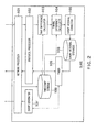
- FIG. 2 is a block diagram of a slave according to the first embodiment.
- the slave includes a network processor 101, a protocol processor 102, a time difference calculator 103, a timing difference calculator 104, an event interval corrector 105, a timer 106, an event generator 107, an event interval storage 108, and a timestamp storage 109.
- the network processor 101 is an interface that transmits and receives frames to and from the communication network.
- the frames include an event frame that reports the content of an event (for example, the value of the quantity of electricity) and a synchronous frame. Other types of frames may be provided.
- the timer 106 has a crystal oscillator and includes a clocking unit that performs time keeping by counting the periods of output signals from the crystal oscillator. The time advances by one at every count.
- the network processor 101 includes a function to record a timestamp representing a time when a synchronous frame is transmitted and a timestamp representing a time when a synchronous frame is received.
- the timestamp represents a time currently indicated by the clocking unit.
- the protocol processor 102 processes a common format for information transmitted and received by apparatuses constituting the synchronous system and a procedure for transmission and reception.
- the protocol processor 102 has a function to pass, to the time difference calculator 103, a timestamp (described below) recorded in a synchronous frame received from a master.
- the event interval storage 108 stores event interval information representing a time interval for event generation. As a default value, for example, the same event interval value as that in the master is stored.
- the timer 106 generates a signal indicating a timing of event generation when a preset time elapses and transmits the signal to the event generator 107.
- a value for event interval information currently stored in the event interval storage 108 is set as the amount of time until the next event is generated.
- the set time elapses a signal is generated.
- the value in the event interval storage 108 may be read to set the value as the amount of time until the next event is generated, or after outputting the signal, the timer 106 itself may read the value from the event interval storage 108 and autonomously carry out the setting. An error occurs between the crystal oscillators in the master and the slave, and thus, a speed at which the time advances varies between the master and the slave.
- the event generator 107 Upon receiving the signal from the timer 106, the event generator 107 generates an event. In the protective relay system, the value of the quantity of electricity measured by a measuring unit (not shown in the drawings) is recorded in an event frame, which is then passed to the network processor 101.
- the timer 106 generates a signal indicating a timing for transmission of a synchronous frame and transmits the signal to the protocol processor 102.
- the amount of time until the signal is generated is set in the timer 106 by, for example, the protocol processor 102.
- the timer 106 outputs the signal to the protocol processor 102.
- a transmission timing for a synchronous frame may be determined by any method. For example, a signal for a timing for transmission of a synchronous frame may be generated a given time after a signal for a timing of event generation is generated. Alternatively, the signal for the timing for transmission of a synchronous frame may be generated in response to an indication of transmission from the master. Alternatively, the signal for the timing for transmission of a synchronous frame may be generated at a preset constant time interval.
- the protocol processor 102 Upon receiving the signal from the timer 106, the protocol processor 102 generates and transmits a synchronous frame to the master via the network processor 101.
- a timestamp representing a time (count value) of transmission of the synchronous frame (hereinafter referred to as a slave transmission timestamp) may be added to the synchronous frame.
- a timestamp representing a time when an event is generated in the slave (hereinafter referred to as a slave event generation timestamp) may be contained in the synchronous frame.
- the time when the event is generated may be, for example, a time when the latest event is generated before the synchronous frame is transmitted.
- the timestamp storage 109 stores the slave event generation timestamp, the slave transmission timestamp, and a timestamp representing a time when a synchronous frame is received from the master (slave reception timestamp).
- the timestamp storage 109 may also store a timestamp representing a time when the master receives a synchronous frame from the slave (master reception timestamp) and a timestamp representing a time when the master transmits a synchronous frame to the slave (master transmission timestamp).
- a method for acquiring the timestamps will be described below.
- the slave event generation timestamp represents a time when the network processor 101 transmits an event frame in which the quantity of electricity is recorded by the event generator 107.
- the slave event generation timestamp may represent the time of a timing when the event generator 107 receives a signal for an event or the time of a timing when the value of the quantity of electricity is recorded in the event frame. In this case, the event generator 107 generates the timestamp.
- the slave transmission timestamp and the slave reception timestamp represent a time immediately before the network processor 101 transmits a synchronous frame and a time immediately after the synchronous frame is received.
- the network processor 101 acquires the timestamps.
- the slave transmission timestamp and the slave reception timestamp may represent a time when the protocol processor 102 processes a transmission frame (synchronous frame) and a time when the protocol processor 102 processes a reception frame (synchronous frame). In this case, the protocol processor 102 acquires the timestamps.
- a synchronous frame received from the master contains the timestamp representing the time when the master receives a synchronous frame from the slave (master reception timestamp), the timestamp representing the time when an event is generated in the master (master event generation timestamp), and the timestamp representing the time when the master transmits the synchronous frame to the slave (master transmission timestamp).
- master reception timestamp the timestamp representing the time when the master receives a synchronous frame from the slave
- master event generation timestamp the timestamp representing the time when an event is generated in the master
- master transmission timestamp master transmission timestamp
- the time difference calculator 103 utilizes the timestamps passed by the protocol processor 102 (the master reception timestamp and the master transmission timestamp) and the timestamps in the timestamp storage (the slave transmission timestamp and the slave reception timestamp) to calculate a time difference between the slave and the master.
- the time difference calculator 103 passes the time difference between the slave and the master to the timing difference calculator 104.
- a configuration is also possible in which the slave transmission timestamp is received from the protocol processor 102.
- a configuration is also possible in which the slave reception timestamp is received from the protocol processor 102 (this will be described below in detail).
- the timing difference calculator 104 utilizes the time difference between the timer in the slave and the timer in the master received from the time difference calculator 103, the master event generation timestamp (recorded in the synchronous frame from the master), and the slave event generation timestamp to calculate the amount of time from event generation in the slave until event generation in the master (a difference in timing of event generation between the slave and the master).
- the slave event generation timestamp, slave transmission timestamp, and slave reception timestamp stored in the timestamp storage 109 in the slave may be utilized.
- the timestamps may be read from a synchronous frame received from the master. This is because the master transcribes the timestamps to a synchronous frame transmitted by the master to the slave. Furthermore, a configuration is possible in which, when the synchronous frame is received from the master, the slave reception timestamp is added to a predetermined field of the synchronous frame, which is then passed by the protocol processor 102. In this case, reading from the timestamp storage is also unnecessary.
- the event interval corrector 105 corrects the event interval information to zero or reduce the difference in event timing between the slave and the master received from the timing difference calculator 106.
- the value in the event interval storage 108 is updated based on the corrected event interval information.
- the updated value in the event interval storage 108 is newly set in the timer 106.
- the timer 106 outputs the event signal to allow the event generator 107 to generate an event.
- event generation in the master can be accurately synchronized with event generation in the slave.
- the value in the event interval storage may be returned to the default value of the event interval (the same event interval value as that in the master).
- correction may be made to a plurality of sets of events on a step by step basis instead of being made to all the events at a time. That is, the event interval information may be corrected each time an event is generated so that the value for the event interval information becomes gradually closer to the calculated value of the event interval each time an event is generated.
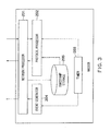
- FIG. 3 is a block diagram of the master according to the first embodiment.
- the master includes a network processor 201, a protocol processor 202, a timer 203, an event generator 204, and a timestamp storage 205.
- the network processor 201 is an interface that transmits and receives frames to and from the communication network 12.
- the types of frames include a synchronous frame and an event frame. Other types of frames may be provided.
- the protocol processor 202 processes a common format for information transmitted and received by apparatuses constituting the synchronous system and a procedure for transmission and reception.
- the timer 203 generates a signal indicating a timing of event generation each time a given amount of time elapses, and transmits the signal to the event generator 204.
- the timer 203 includes a crystal oscillator and a clocking unit that performs time keeping by counting the periods of output signals from the crystal oscillator. The description of the first embodiment assumes that a count value represents a time.
- the event generator 204 receives a signal from the timer 203 to generate an event.
- the value of the quantity of electricity measured by a measuring unit (not shown in the drawings) is recorded in a frame (event frame), which is then passed to the network processor 201.
- the network processor 201 transmits the frame to a pre-designated another protective relay apparatus.
- the timestamp storage 205 stores the timestamp representing the time when the master receives a synchronous frame from the slave (master reception timestamp), the timestamp representing the time when the master transmits a synchronous frame to the slave (master transmission timestamp), and the timestamp representing the time when an event is generated in the event generator 204 (master event generation timestamp).
- the master event generation timestamp represents a time immediately before the network processor 201 transmits an event frame in which the quantity of electricity is recorded by the event generator 204. In this case, the network processor 201 acquires the timestamp.
- the master event generation timestamp may represent the time of a timing when the event generator 204 receives a signal for an event or the time of a timing when the value of the quantity of electricity is recorded in the event frame. In this case, the event generator 204 acquires the timestamp.
- the master reception timestamp and the master transmission timestamp represent a time immediately after the network processor 204 receives a synchronous frame or a time immediately before the network processor 204 transmits a synchronous frame. In this case, the network processor 204 acquires the timestamps.
- the master reception timestamp and the master transmission timestamp may represent a time when the protocol processor 202 processes a reception frame (synchronous frame) or a transmission frame (synchronous frame). In this case, the protocol processor 202 acquires the timestamps.
- the protocol processor 202 Upon receiving a synchronous frame from the slave, the protocol processor 202 generates a synchronous frame to be returned to the slave.
- the synchronous frame to be transmitted to the slave contains the master event generation timestamp (for example, a timestamp for a time when the latest event is generated), the master reception timestamp, and the master transmission timestamp.
- the master event generation timestamp for example, a timestamp for a time when the latest event is generated
- the master reception timestamp for example, a timestamp for a time when the latest event is generated
- the master transmission timestamp for example, a timestamp for a time when the latest event is generated
- the master transmission timestamp for example, a timestamp for a time when the latest event is generated
- the master transmission timestamp for example, a timestamp for a time when the latest event is generated
- the master transmission timestamp for example, a timestamp for a time when the latest event is generated
- a sequence of exchange of synchronous frames between the slave and the master will be described with reference to FIG. 8 .
- the slave transmission timestamp is denoted by "t1", and the master reception timestamp is denoted by "t2".
- the master transmission timestamp is denoted by "t3”, and the slave reception timestamp is denoted by "t4".
- the timestamps are exchanged between the slave and the master via synchronous frames.
- the timestamp "t1" may be recorded in a synchronous frame transmitted by the slave, then transcribed to a synchronous frame transmitted by the master, and thus transmitted again to the slave.
- the timestamp "t1" may be stored in the timestamp storage 109 in the slave without being recorded in the synchronous frame to be transmitted to the master.
- the timestamps "t2" and "t3" are recorded in the synchronous frame transmitted by the master.
- "t3 - t2" may be recorded in the synchronous frame.
- a subtraction is denoted by "-”.
- the slave first transmits a synchronous frame, and in response to the synchronous frame, the master transmits a synchronous frame.
- the first embodiment is not limited to this sequence and another sequence is possible.
- a method is possible in which the master transmits a frame that urges the slave to transmit a synchronous frame before the sequence shown in FIG. 8 is started.
- the slave and the master transmit synchronous frames to each other in accordance with respective independent timings.
- the sequence for synchronous frames is carried out a plurality of times regularly or irregularly instead of being carried out only once.
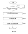
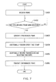
- FIG. 4 is a flowchart showing an operation of the slave during transmission of a synchronous frame.
- the protocol processor 102 waits until the protocol processor 102 receives, from the timer 106, a signal indicating that a period for transmission of a synchronous frame has come (step S101).
- the protocol processor 102 receives a signal from the timer 106, then generates a synchronous frame destined for the master, and passes the synchronous frame to the network processor 101 (step S102). At this time, the protocol processor 102 may set a time for generation of the next synchronous frame in the timer 106.
- the network processor 101 records, in the timestamp storage 109, the timestamp (slave transmission timestamp) "t1" representing the time when a synchronous frame is to be transmitted (step S103).
- the timestamp "t1" may be recorded in the synchronous frame to be transmitted instead of being recorded in the timestamp storage 109.
- the generation of the timestamp may be carried out by the protocol processor 102 during generation of a synchronous frame.
- the slave event generation timestamp may be recorded in the synchronous frame.
- the network processor 101 transmits the synchronous frame to the master (step S104).
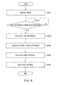
- FIG. 5 is a flowchart showing an operation of the slave during reception of a synchronous frame.
- the network processor 101 receives a frame and passes the received frame to the protocol processor 102.
- the timestamp (slave reception timestamp) "t4" representing the time of reception of the frame is recorded in the timestamp storage 109 (step S201).
- a configuration is also possible in which the timestamp "t4" is additionally recorded in a predetermined field in the received frame instead of being recorded in the timestamp storage 109.
- the protocol processor 102 determines whether or not the received frame is a synchronous frame (step S202).
- the protocol processor 102 carries out processing depending on the type of the frame, and the system waits again to receive a frame.
- the timestamp "t4" recorded in the timestamp storage 109 may be erased.
- the timestamp "t4" may be neglected during processing of the frame.
- the frame received from the master is a synchronous frame
- a plurality of timestamps recorded in the synchronous frame is read and passed to the time difference calculator 103. Furthermore, the timestamps may be stored in the timestamp storage 109.
- the timestamps recorded in the synchronous frame received from the master include the master reception timestamp "t2", the master transmission timestamp "t3", and the master event generation timestamp.
- the difference in timestamp "t3 - t2" is recorded instead of the timestamps "t2" and "t3”
- the value "t3 - t2" is passed to the time difference calculator 103 instead of the timestamps "t2" and "t3”.
- the value "t3 - t2" may be stored in the timestamp storage 109.
- the timestamp is also passed to the time difference calculator 103.
- the time difference calculator 103 utilizes the timestamps "t1", “t2", “t3”, and "t4" to calculate the difference in time between the slave and the master (step S203).
- the timestamps "t1" and "t4" are not received from the protocol processor 102, the timestamps "t1” and "t4" are acquired by being read from the timestamp storage 109. A method for calculating the time difference between the slave and the master will be described below.
- the time difference calculator 103 passes the calculated time difference and the master event generation timestamp passed by the protocol processor 102, to the timing difference calculator 104.
- the time difference calculator 103 may receive the result of "t4 - t1" from the protocol processor 102 instead of the timestamps "t1" and "t4" and calculate the time difference utilizing the result.
- a configuration is also possible in which the result of "t4 - t1" is received from any processor that can access the timestamp storage 109 rather than from the protocol processor 102.
- Communication delay min ⁇ t ⁇ 4 i - t ⁇ 3 i + min ⁇ t ⁇ 2 i - t ⁇ 1 j 2
- the difference between slave and master t ⁇ 4 argmin ⁇ t ⁇ 4 ⁇ i - t ⁇ 3 ⁇ i - t ⁇ 3 argmin ⁇ t ⁇ 4 ⁇ i - t ⁇ 3 ⁇ i + communication delay
- the smallest one of the values "t2 - t1" for N synchronous frames that have been transmitted from the slave to the master is denoted by "min(t2 j - t1 j )" (one of the numbers 1 to N is denoted by “j”).
- the smallest one of the values "t4 - t3" for N synchronous frames that have been transmitted from the master to the slave is denoted by "min(t4i - t3i)" (one of the numbers 1 to N is denoted by "i”).
- Selection of the respective smallest values allows selection of synchronous frames with the shortest communication delay from the synchronous frames transmitted from the slave to the master and from the synchronous frames transmitted from the master to the slave.
- Short communication delays in both directions mean that the communication delays in the two directions are likely to be the same or very close.
- Halving the roundtrip delay for synchronous frames with a maximally equal communication delay allows the calculated communication delay in one way to be made closer to the real delay in the communication between the master and the slave.
- the time difference between the slave and the master can be calculated as described above using "t3 argmin ("t4"i-"t3”i)” obtained when “t4 - t3" results in the smallest value and “t4 argmin ("t4"i-"t3”i)” obtained when "t4 - t3" results in the smallest value.
- a certain range of values may be allowed for the selection, for example, not only the smallest value for the past N synchronous frames but also the second smallest value may be selected.
- the timing difference calculator 104 uses the time difference between the slave and the master passed by the time difference calculator 103, the master event generation timestamp, and the slave event generation timestamp stored in the timestamp storage 109 to calculate the amount of time from event generation in the slave until event generation in the master (the difference in timing of event generation between the slave and the master).
- a configuration is also possible in which the slave event generation timestamp is received from the protocol processor 102 via the time difference calculator 103.
- the timing difference calculator 104 passes the calculated timing difference between the events in the slave and the master to the event interval corrector 105.
- FIG. 9 is a diagram illustrating the difference between the time difference between the slave and the master and the timing difference between events in the slave and the master.
- Any time in a master reference time is denoted by “t”.
- a time in a slave reference time at the time “t” in the master reference time is denoted by “st(t)”.
- Event generation is denoted by " ⁇ ”.
- An event generation time in the master in the master reference time is denoted by "tem”.
- An event generation time in the slave in the master reference time is denoted by "tes".
- An event generation time in the slave in the slave reference time is denoted by "st(tes)".
- the master event generation timestamp corresponds to "tem”
- the slave event generation timestamp corresponds to "st(tes)”.
- a time difference between the slave and the master observed when the time in the master reference time is "tes” is "tes - st(tes)”. The time difference corresponds to a value received from the time difference calculator 103.
- the timing difference between the slave and the master based on the master reference time is "tes - tem".
- "tes” is a time in the master reference time when an event is generated in the slave and thus fails to be measured.
- the amount of time from the event generation in the slave until the event generation in the master is expressed as follows.
- the amount of time from the event generation in the slave until the event generation in the master st(tes) - tem - (the time difference between the slave and the master)
- step S205 the event interval corrector 105 corrects the event interval based on the amount of time from event generation in the slave until event generation in the master (the timing difference between events in the slave and the master).
- the value of the event interval currently set in the event interval storage 108 is corrected to reduce the amount of time from the event generation in the slave until the event generation in the master (the timing difference between the events in the slave and the master), for example, to zero the amount of time.
- the timing difference between the events in the slave and the master is "x" (or "-x)
- the event interval is reduced (or increased) by "x”.
- the event interval may be reduced (increased) a plurality of times so that the event interval decreases (increases) by "x" in total through a number of event generations.
- the event interval corrector 105 saves the corrected event interval to the event interval storage 108 (step S206).
- the corrected value of the event interval in the event interval storage 108 is then set in the timer 106.
- the value in the event interval storage 108 may be set equal to the default value of the event interval (the same event interval value as that set in the master).
- the timing difference between the events in the slave and the master calculated in step S204 described above is desirably the amount of time between an event in the slave and an event in the master temporally closest to the event in the slave.
- the event in the slave as used herein may be any event, for example, the last event generated before transmission of a synchronous frame to the master, the latest event generated immediately before reception of a synchronous frame from the master or the like.
- the event in the master close to the event in the slave may be an event in the master to be generated in the future instead of an already generated event.
- the master event generation timestamp "tem" (see FIG. 9 ) obtained from the synchronous frame may not be indicative of the time of generation of the event in the master temporally closest to the event in the slave. Thus, a manner of determining the amount of time between the event in the slave and the temporally closest event in the master (timing difference) will be illustrated.
- the preceding event A in the master has a smaller time difference from the event 1 than the succeeding event B in the master.
- the preceding event A is defined as the event in the master temporally closest to the event 1 in the slave.
- the succeeding event B in the master has a smaller time difference from the event 1
- the succeeding event is defined as the event in the master temporally closest to the event 1.
- an event in the master with the timestamp "tem" (see FIG. 9 ) obtained from a synchronous frame may not indicate the time of an event temporally closest to the event in the slave. This is because an amount of time elapses from recording of the master event generation timestamp in a synchronous frame until the slave receives the synchronous frame. Thus, it is unknown which of the events in the slave is temporally closest to the master event generation timestamp recorded in the synchronous frame.
- the event timing difference obtained by the calculation method illustrated in the description of step S204 may indicate an amount of time from event generation in the slave which corresponds to a plurality of events in the master.
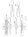
- a method for estimating the timing difference between an event in the slave and the temporally closest event in the master will be described with reference to FIG. 11 .
- This process can be applied in the processing in step S204 in FIG. 5 .
- step S500 the timing difference between the events in the slave and the master obtained by the calculation method illustrated in step S204 described above is provided for a parameter "Z" (step S500).
- the parameter "Z” is compared with the default event interval (the same value as that in the master) (step S501).
- the parameter "Z” is divided by the event interval to determine the remainder, which is then input to the parameter "Z" (step S502).
- step S501 When, in step S501, the parameter "Z" is equal to or smaller than the event interval or after step S502 is carried out, the parameter "Z" is compared with half of the event interval (step S503).
- step S503 the parameter "Z" is determined to be equal to or smaller than the half of the event interval or after step S504 is carried out, the value of the parameter "Z” is determined to be the timing difference between the event in the slave and the temporally closest event in the master (step S505).
- the above-described processing allows estimation of the amount of time from generation of an event in the slave until generation of an event in the master temporally closest to the event in the slave (the timing difference between the events in the slave and the master).
- FIG. 6 is a flowchart showing operations performed by the slave shown in FIG. 2 and the master shown on FIG. 3 during event generation.
- the event generator 107 or 204 wait until the event generator 107 or 204 receive a signal from the timer 106 or 203 (step S301).
- the event generator 107 or 204 carries out event processing (step S302).
- the event processing involves acquiring the value of the quantity of electricity (a current value or a voltage value) and recording the value in an event frame.
- the event generator 107 or 204 may set the amount of time until the next event in the timer 106 or 203.
- the slave sets a value stored in the event interval storage 106, and the master sets a predetermined event interval value.
- the network processor 101 or 201 generates a timestamp for the time of event generation (the slave event generation timestamp or the master event generation timestamp) and records the timestamp in the event frame (step S303).
- the network processor 101 or 201 transmits the event frame to the communication network 102 (step S304).
- a destination recorded in the event frame is pre-provided and added to the event frame by the event generator or the network processor.
- FIG. 7 is a flowchart showing operations of the master shown in FIG. 3 during reception of a synchronous frame.
- the network processor 201 receives a frame from the communication network 102 and passes the received frame to the protocol processor 202.
- the timestamp (master reception timestamp) "t2" for the time of frame reception is recorded in the timestamp storage 205.
- the master reception timestamp may be additionally recorded in a predetermined field of the frame (step S401).
- the protocol processor 202 determines whether or not the received frame is a synchronous frame (step S402).
- the received frame is not a synchronous frame
- processing depending on the type of the frame is carried out, and the system waits again to receive a frame.
- the timestamp "t2" recorded in the timestamp storage 205 may be erased.
- the timestamp "t2" may be neglected during processing of the frame.
- the protocol processor 202 When the received frame is a synchronous frame, the protocol processor 202 generates a synchronous frame destined for the slave (step S403).
- the destined slave may be identified with reference to a source address in the synchronous frame.
- the protocol processor 202 acquires the master event generation timestamp from the timestamp storage 205 and additionally records the timestamp in the synchronous frame (step S404).
- An event for which the timestamp is generated is the latest event generated in the master. However, the event is not limited to the latest event but may be an older event.
- the protocol processor 202 records the master event generation timestamp, the master reception timestamp "t2", the master transmission timestamp "t3" in a synchronous frame to be transmitted to the slave (steps S404 and S405).
- the timestamps "t3" and "t2” a difference between the above-described two timestamps "t3 - t2" may be recorded.
- the timestamp “t3” desirably represents a time immediately before the network processor 201 carries out transmission. However, the timestamp "t3" may represent a time when the protocol processor 204 generates the synchronous frame.
- the synchronous frame received by the master from the slave may contain the slave transmission timestamp "t1" or the slave event generation timestamp.
- the timestamp is also recorded in the synchronous frame destined for the slave.
- the network processor 201 transmits the synchronous frame destined for the slave (step S406).
- the first embodiment can accurately synchronize the timing of event generation in the slave with the timing of event generation in the master by determining the difference in timing of event generation between the slave and the master based on the time difference between the slave and the master and correcting the information on the event interval in the slave so as to reduce the timing difference.
- the event generation in the slave can be quickly and accurately synchronized with the event generation in the master by determining the timing difference between an event in the slave and the temporally closest event in the master.
- the first embodiment determines the timing difference between events in the slave and the master based on the time difference between the slave and the master and corrects the event interval based on the event timing difference.
- a second embodiment determines the time difference between the slave and the master based on the timing difference between events in the slave and the master, determines a time parameter based on the time difference, and further determines the event interval.
- FIG. 12 is a block diagram of a slave according to the second embodiment.
- the slave includes a network processor 101, a protocol processor 102, a timing difference calculator 111, a time difference calculator 112, a timestamp storage 109, a timer 106, an event generator 107, a time parameter storage 114, and a time calculator (event interval calculator) 115.
- a main difference between the second embodiment and the first embodiment is that the time difference calculator 103, the timing difference calculator 104, the event interval corrector 105, and the event interval storage 108 according to the first embodiment are removed and that the timing difference calculator 111, the time difference calculator 112, the time parameter storage 114, and the time calculator 115 are added.
- Duplicate description of the same processing as that in the first embodiment is omitted except for a changed or expanded part of the processing.
- the timing difference calculator 111 utilizes timestamps passed by the protocol processor 102 (the master event generation timestamp and the master reception timestamp) and timestamps in the timestamp storage 109 (the slave reception timestamp and the slave event generation timestamp) to calculate the amount of time from event generation in the slave until event generation in the master (the timing difference between events in the slave and the master). As is the case with the first embodiment, a configuration is also possible in which the timestamps in the timestamp storage 109 are acquired from the protocol processor 102. The timing difference calculator 111 passes the calculated event timing difference to the time difference calculator 112.
- the time difference calculator 112 utilizes the timing difference between events in the slave and the master received from the timing difference calculator 111, the master event generation timestamp, and the slave event generation timestamp stored in the timestamp storage 109 to calculate the time difference between the slave and the master.
- the slave event generation timestamp and slave transmission timestamp recorded in the timestamp storage 109 in the slave may be utilized.
- the two timestamps may be recorded in a synchronous frame to be transmitted by the slave to the master, then transcribed when the master transmits a synchronous frame to the slave, and received by the slave for utilization.
- the time difference calculator 112 obtains the time difference between the slave and the master as a clock offset. Furthermore, a clock rate is calculated as necessary which represents the ratio of time advancement speed of the master to the slave.
- the clock offset and the clock rate are collectively referred to as a time parameter.
- a configuration is also possible in which the calculation of the clock rate is omitted. In this case, the value of the clock rate may be set to 1 and then the subsequent processing may be carried out.
- the clock rate results from a difference in oscillation frequency between the crystal oscillators in the slave and the master.
- For the clock rate for example two synchronization processes (see FIG. 8 ) are carried out to acquire times "t4(1)” and "t4(2)" in the slave and corresponding times "t4'(1)” and “t4'(2)” in the master.
- the times "t4'(1)” and “t4'(2)” are obtained by subtracting the time differences (1) and (2) determined by the time difference calculator 112 during the synchronization processes from the times "t4(1)" and "t4(2)" in the slave, respectively.
- the clock rate can be calculated using " ⁇ t4'(1) - t4'(2) ⁇ / ⁇ t4(1) - t4(2) ⁇ ".
- the clock offset may be acquired using the second or first of the two synchronization processes or a synchronization process after the two synchronization processes.
- the time calculator 115 calculates the amount of time (event interval) to be set in the timer 106 in accordance with the following formula.
- the clock rate may be set to 1, and the event interval may be calculated using default event interval + clock offset.
- the time calculator 115 calculates the event interval in accordance with the above-described formula, and sets the calculated value in the timer 106 as the amount of time until the next event is generated.
- the timer 106 times out to output a signal to the event generator 107.
- the value stored in the time parameter storage 114 is also applied in the next timer process.
- a synchronization process is repeatedly carried out a plurality of times to sequentially update the value of the time parameter. This allows timings for event generation in the slave to be made closer to timings for event generation in the master to enable event generations to be accurately synchronized.
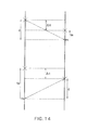
- FIG. 14 shows a sequence of transmission and reception of synchronous frames according to the second embodiment.
- the slave transmits a synchronous frame using event generation as a trigger
- the master also transmits a synchronous frame using event generation as a trigger. Two events are respectively generated during exchange of synchronous frames.
- a timestamp representing a time when the master receives a synchronous frame is denoted by "rm”.
- a timestamp representing a time when the slave receives a synchronous frame is denoted by "rs”.
- the timestamp "rm” and a timestamp for an event generated immediately before “rm” in the master are recorded in a synchronous frame to be transmitted by the master in response to an event generated after "rm", and the synchronous frame is then transmitted the slave.
- a delay time "d" is the same for the transmission of a synchronous frame from the slave to the master and the transmission of a synchronous frame from the master to the slave.
- “d” is not necessarily the same, and a difference in delay time is an error between calculated " ⁇ t” and actual “ ⁇ t”.
- the amount of time from event generation in the slave until event generation in the master is denoted by " ⁇ t”.
- both calculated " ⁇ t” and actual “ ⁇ t” have the same value.
- the calculated " ⁇ t” and the actual “ ⁇ t” are not necessarily the same, and the difference is an error between the calculated " ⁇ t” and the actual “ ⁇ t”.
- a difference between the master event generation timestamp and the master reception timestamp "rm” is denoted by “tm”.
- a difference between the slave reception timestamp "rs” and the slave event generation timestamp is denoted by "ts”. This will be described below in detail.
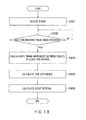
- FIG. 13 is a flowchart showing operations of the slave according to the second embodiment during reception of a synchronous frame.
- the network processor 101 receives a frame from the master and passes the frame to the protocol processor 102.
- a timestamp (slave reception timestamp) "rs" representing the time of reception of the frame is recorded in the timestamp storage 109.
- the slave reception timestamp may be additionally recorded in the synchronous frame (step S601).
- the protocol processor 102 determines whether or not the received frame is a synchronous frame (step S602). When the received frame is a synchronous frame, the protocol processor 102 passes the master reception timestamp "rm" and master event generation timestamp recorded in the synchronous frame to the timing difference calculator 111.
- the timing difference calculator 111 utilizes the timestamps received from the protocol processor 102, the slave reception timestamp, and the slave event generation timestamp to calculate the timing difference between the events in the slave and the master (step S604).
- the calculated event timing difference and the master event generation timestamp are passed to the time difference calculator 112.
- the timing difference may not be the timing difference between temporally close events in the slave and the master.
- the timing difference between the temporally close events in the slave and the master can be estimated by carrying out a conversion process similar to the conversion process shown in FIG. 10 for the first embodiment on the timing difference calculated in accordance with the above-described formula.
- the time difference calculator 112 utilizes the timing difference passed by the timing difference calculator 111, the master event generation timestamp, and the slave event generation timestamp passed by the timestamp storage 109 to calculate the time difference between the slave and the master. Then, the time difference is stored in the time parameter storage 114 as a clock offset (step S604). Furthermore, the clock rate is calculated as necessary and stored in the time parameter storage 114. A method for calculating the clock rate is as described above.
- FIG. 9 is a diagram illustrating the time difference and timing difference between the slave and the master.
- the definitions of variables shown in FIG. 9 are as described above.
- the master event generation timestamp corresponds to "tem”
- the slave event generation timestamp corresponds to "st(tes)".
- the event timing difference received from the timing difference calculator 111 corresponds to the value "tes - tem”.
- the time difference between the slave and the master for "st(tes)" is equal to "tes - st(tes)”.
- "tes” corresponds to a time in the master reference time when an event is generated in the slave and thus fails to be measured.
- the time calculator 115 calculates the amount of time (event interval) to be set in the timer 106 based on the time parameter in the time parameter storage 114 and sets the calculated value in the timer 106 (step S605).
- a timing for the calculation of the event interval may be a point in time corresponding to the last timeout of the timer 106 or the event interval may be calculated before the last timeout and stored in an internal buffer or a separate storage so that, when the timer 106 times out, the buffered value can be read and set in the timer 106.
- the timer 106 When the set event interval elapses, the timer 106 generates a signal.
- the second embodiment determines the time difference between the slave and the master based on the timing difference between events in the slave and the master, then determines the time parameter (the clock offset (equal to the time difference itself) or the clock rate) based on the time difference, and determines the next event interval based on the parameter. Repeating such processing enables the event timing in the slave to be made gradually closer to the event timing in the master, allowing the event generation in the slave to be accurately synchronized with the event generation in the master.
- the time parameter the clock offset (equal to the time difference itself) or the clock rate
- calculating the time difference based on the timing difference between events enables not only the event synchronization but also diversion of the time difference to measurement of the communication delay, another application that needs synchronization, or the like.
- the first embodiment illustrates the example in which the event interval is adjusted on a step by step basis through a plurality of events.
- the event interval may also be reduced on a step by step basis through a plurality of events.
- the time calculator may change the value for the event interval information each time an event is generated so that the value for the event interval information becomes closer to the calculated value for the event interval information each time an event is generated.
- the slave and the master as described above may also be realized using a general-purpose computer device as basic hardware. That is, processing of each block in the slave and the master can be realized by causing a processor mounted in the above general-purpose computer device to execute a program.
- the slave and the master may be realized by installing the above described program in the computer device beforehand or may be realized by storing the program in a storage medium such as a CD-ROM or distributing the above described program over a network and installing this program in the computer device as appropriate.
- the storage in the slave and the master may also be realized using a memory device or hard disk incorporated in or externally added to the above described computer device or a storage medium such as CD-R, CD-RW, DVD-RAM, DVD-R as appropriate.
Landscapes
- Engineering & Computer Science (AREA)
- Computer Networks & Wireless Communication (AREA)
- Signal Processing (AREA)
- Computer Security & Cryptography (AREA)
- Synchronisation In Digital Transmission Systems (AREA)
Applications Claiming Priority (1)
| Application Number | Priority Date | Filing Date | Title |
|---|---|---|---|
| JP2013118230A JP6192995B2 (ja) | 2013-06-04 | 2013-06-04 | 通信装置、通信システム、通信方法およびコンピュータプログラム |
Publications (1)
| Publication Number | Publication Date |
|---|---|
| EP2811672A1 true EP2811672A1 (fr) | 2014-12-10 |
Family
ID=50841641
Family Applications (1)
| Application Number | Title | Priority Date | Filing Date |
|---|---|---|---|
| EP20140170581 Withdrawn EP2811672A1 (fr) | 2013-06-04 | 2014-05-30 | Appareil, procédé et système de communication pour synchronisation d'horloge |
Country Status (3)
| Country | Link |
|---|---|
| US (1) | US9374214B2 (fr) |
| EP (1) | EP2811672A1 (fr) |
| JP (1) | JP6192995B2 (fr) |
Cited By (1)
| Publication number | Priority date | Publication date | Assignee | Title |
|---|---|---|---|---|
| WO2021196090A1 (fr) * | 2020-04-01 | 2021-10-07 | 深圳市汇顶科技股份有限公司 | Procédés de synchronisation temporelle et de configuration de diffusion, puce, dispositif électronique et support de stockage |
Families Citing this family (14)
| Publication number | Priority date | Publication date | Assignee | Title |
|---|---|---|---|---|
| JP6615470B2 (ja) * | 2015-03-16 | 2019-12-04 | 株式会社東芝 | 同期制御装置、同期システム及び同期制御方法 |
| US9853985B2 (en) * | 2015-10-13 | 2017-12-26 | International Business Machines Corporation | Device time accumulation |
| JP6880611B2 (ja) * | 2016-09-14 | 2021-06-02 | 富士電機株式会社 | 処理装置、システム、処理方法および処理プログラム |
| US9979998B1 (en) * | 2017-05-02 | 2018-05-22 | Amazon Technologies, Inc. | System for time synchronization of audio devices |
| US10200724B1 (en) * | 2017-09-12 | 2019-02-05 | Amazon Technologies, Inc. | System for optimizing distribution of audio data |
| US10727965B2 (en) * | 2017-11-21 | 2020-07-28 | Western Digital Technologies, Inc. | System and method for time stamp synchronization |
| US10719100B2 (en) | 2017-11-21 | 2020-07-21 | Western Digital Technologies, Inc. | System and method for time stamp synchronization |
| JP6918268B2 (ja) * | 2019-03-11 | 2021-08-11 | 三菱電機株式会社 | スレーブ機器、時刻同期プログラム、組み込みシステムおよび時刻同期方法 |
| CN113556366B (zh) * | 2020-04-07 | 2023-09-26 | 舜宇光学(浙江)研究院有限公司 | 多传感器数据同步方法及其系统和电子设备 |
| EP3902166B1 (fr) * | 2020-04-21 | 2022-03-23 | TTTech Computertechnik Aktiengesellschaft | Serveur d'horloge tolérant aux erreurs pour un système informatique en temps réel |
| JP7161505B2 (ja) * | 2020-05-29 | 2022-10-26 | 株式会社タムラ製作所 | 情報通信システム及び情報通信装置 |
| US11757614B2 (en) * | 2021-05-10 | 2023-09-12 | Mellanox Technologies, Ltd. | Accurate timestamp correction |
| CN117908354A (zh) * | 2022-10-11 | 2024-04-19 | 比亚迪股份有限公司 | 时间同步系统、域控制器和车辆 |
| WO2025041331A1 (fr) * | 2023-08-24 | 2025-02-27 | 富士通株式会社 | Système de communication et dispositif de communication |
Citations (4)
| Publication number | Priority date | Publication date | Assignee | Title |
|---|---|---|---|---|
| EP0697774A1 (fr) * | 1994-08-15 | 1996-02-21 | Hewlett-Packard Company | Estimation de décalage d'une horloge |
| WO2004038971A1 (fr) * | 2002-10-25 | 2004-05-06 | Siemens Plc. | Procede de determination d'un decalage temporel entre une premiere horloge et une seconde horloge dans un reseau de communication |
| WO2010025743A1 (fr) * | 2008-09-02 | 2010-03-11 | Siemens Enterprise Communications Gmbh & Co. Kg | Procédé de synchronisation d’horloges dans un réseau de communication |
| WO2011079460A1 (fr) * | 2009-12-31 | 2011-07-07 | Abb Research Ltd. | Procédé et appareil pour détecter une asymétrie du retard d'un canal de communication |
Family Cites Families (9)
| Publication number | Priority date | Publication date | Assignee | Title |
|---|---|---|---|---|
| KR101197280B1 (ko) * | 2005-07-15 | 2012-11-05 | 삼성전자주식회사 | 타임 스탬프를 이용한 타임 동기 방법 및 장치 |
| JP4837389B2 (ja) * | 2006-01-31 | 2011-12-14 | 鹿島建設株式会社 | 複数点計測装置および複数点計測方法 |
| JP5127482B2 (ja) | 2008-01-30 | 2013-01-23 | 株式会社東芝 | タイミング同期方法、同期装置、同期システム及び同期プログラム |
| US8473638B2 (en) | 2008-05-02 | 2013-06-25 | James Aweya | Method and apparatus for time and frequency transfer in communication networks |
| JP5332421B2 (ja) * | 2008-09-05 | 2013-11-06 | 横河電機株式会社 | 計測レコーダ・システム |
| JP5259663B2 (ja) * | 2010-09-15 | 2013-08-07 | 株式会社東芝 | 計測装置およびプログラム |
| JP5849413B2 (ja) * | 2011-03-18 | 2016-01-27 | セイコーエプソン株式会社 | 情報通信端末、生体情報測定機器及び情報通信システム |
| US8959381B2 (en) * | 2012-09-05 | 2015-02-17 | Khalifa University of Science, Technology, and Research | Method and system for clock offset and skew estimation |
| JP6183639B2 (ja) * | 2013-04-24 | 2017-08-23 | 株式会社チノー | センシングシステム |
-
2013
- 2013-06-04 JP JP2013118230A patent/JP6192995B2/ja not_active Expired - Fee Related
-
2014
- 2014-05-30 EP EP20140170581 patent/EP2811672A1/fr not_active Withdrawn
- 2014-06-02 US US14/293,207 patent/US9374214B2/en not_active Expired - Fee Related
Patent Citations (4)
| Publication number | Priority date | Publication date | Assignee | Title |
|---|---|---|---|---|
| EP0697774A1 (fr) * | 1994-08-15 | 1996-02-21 | Hewlett-Packard Company | Estimation de décalage d'une horloge |
| WO2004038971A1 (fr) * | 2002-10-25 | 2004-05-06 | Siemens Plc. | Procede de determination d'un decalage temporel entre une premiere horloge et une seconde horloge dans un reseau de communication |
| WO2010025743A1 (fr) * | 2008-09-02 | 2010-03-11 | Siemens Enterprise Communications Gmbh & Co. Kg | Procédé de synchronisation d’horloges dans un réseau de communication |
| WO2011079460A1 (fr) * | 2009-12-31 | 2011-07-07 | Abb Research Ltd. | Procédé et appareil pour détecter une asymétrie du retard d'un canal de communication |
Non-Patent Citations (4)
| Title |
|---|
| BIAN BAOYIN ET AL: "Risk analysis and research based on IEEE 1588 in Smart high voltage substation", INNOVATIVE SMART GRID TECHNOLOGIES - ASIA (ISGT ASIA), 2012 IEEE, IEEE, 21 May 2012 (2012-05-21), pages 1 - 7, XP032237612, ISBN: 978-1-4673-1221-9, DOI: 10.1109/ISGT-ASIA.2012.6303307 * |
| KANG WANG ET AL: "Research and design on time synchronization technology of smart substation based on IEEE1588", ADVANCED POWER SYSTEM AUTOMATION AND PROTECTION (APAP), 2011 INTERNATIONAL CONFERENCE ON, IEEE, 16 October 2011 (2011-10-16), pages 2244 - 2248, XP032162743, ISBN: 978-1-4244-9622-8, DOI: 10.1109/APAP.2011.6180800 * |
| LINGANG FAN ET AL: "The analysis of Clock Synchronization Protocol on Ethernet", REMOTE SENSING, ENVIRONMENT AND TRANSPORTATION ENGINEERING (RSETE), 2011 INTERNATIONAL CONFERENCE ON, IEEE, 24 June 2011 (2011-06-24), pages 826 - 829, XP031905250, ISBN: 978-1-4244-9172-8, DOI: 10.1109/RSETE.2011.5964405 * |
| MILLS D L: "INTERNET TIME SYNCHRONIZATION: THE NETWORK TIME PROTOCOL", IEEE TRANSACTIONS ON COMMUNICATIONS, IEEE SERVICE CENTER, PISCATAWAY, NJ. USA, vol. 39, no. 10, 1 October 1991 (1991-10-01), pages 1482 - 1493, XP000275311, ISSN: 0090-6778, DOI: 10.1109/26.103043 * |
Cited By (2)
| Publication number | Priority date | Publication date | Assignee | Title |
|---|---|---|---|---|
| WO2021196090A1 (fr) * | 2020-04-01 | 2021-10-07 | 深圳市汇顶科技股份有限公司 | Procédés de synchronisation temporelle et de configuration de diffusion, puce, dispositif électronique et support de stockage |
| US12363661B2 (en) | 2020-04-01 | 2025-07-15 | Shenzhen GOODIX Technology Co., Ltd. | Method for time synchronization, method for broadcast setting, chip, electronic device, and storage medium |
Also Published As
| Publication number | Publication date |
|---|---|
| JP6192995B2 (ja) | 2017-09-06 |
| JP2014236443A (ja) | 2014-12-15 |
| US9374214B2 (en) | 2016-06-21 |
| US20140355629A1 (en) | 2014-12-04 |
Similar Documents
| Publication | Publication Date | Title |
|---|---|---|
| US9374214B2 (en) | Communication apparatus, communication system, and communication method | |
| US9634782B2 (en) | Clock synchronization system, clock synchronization method, and storage medium whereupon clock synchronization program is stored | |
| US9671761B2 (en) | Method, time consumer system, and computer program product for maintaining accurate time on an ideal clock | |
| EP3284217B1 (fr) | Procédés, systèmes et supports lisibles par ordinateur pour synchroniser une temporisation entre des cartes d'interface réseau (nic) dans un dispositif de test d'équipement de réseau | |
| US9923656B2 (en) | Methods, systems, and computer readable media for testing recovered clock quality | |
| EP4044466B1 (fr) | Procédé et dispositif de synchronisation | |
| US10404393B2 (en) | Clock synchronization method and apparatus | |
| KR101685856B1 (ko) | 보정 파라미터 산출 장치 및 시스템 및 보정 파라미터 산출 방법 및 컴퓨터 프로그램 | |
| JP2009111654A (ja) | 時刻同期処理システム、時刻情報配信装置、時刻同期処理装置、時刻情報配信プログラム、および時刻同期処理プログラム | |
| WO2015122175A1 (fr) | Dispositif de synchronisation temporelle, système de synchronisation temporelle et procédé de synchronisation temporelle | |
| CN105207767A (zh) | 一种ptp主时钟与从时钟之间频率同步的方法及装置 | |
| EP3231110B1 (fr) | Procédé et dispositifs de transfert temporel a l'aide d'horloges transparentes de bout en bout | |
| CN115623579A (zh) | 一种基站的时钟同步方法及装置 | |
| CN117294378A (zh) | 一种时钟同步方法、装置和系统 | |
| EP3068076A1 (fr) | Détermination automatique de retard asymétrique dans des réseaux de transmission | |
| EP3732806B1 (fr) | Procédé, dispositif et système d'estimation de décalage, d'obliquité et de dérive | |
| EP2398173A1 (fr) | Système E/S distant et son procédé de synchronisation | |
| JP2014190735A (ja) | 情報装置およびその時刻同期方法 | |
| JP2020053737A (ja) | 情報通信システム | |
| JP6627958B1 (ja) | 通信システム | |
| CN110138487A (zh) | 一种时间噪声传递特性测量方法和网络节点 | |
| CN118101108A (zh) | 主节点时钟同步方法、从节点时钟同步方法及设备 | |
| JP2020053738A (ja) | 情報通信システム | |
| JP2021057696A (ja) | 無線通信装置及び時刻同期プログラム |
Legal Events
| Date | Code | Title | Description |
|---|---|---|---|
| PUAI | Public reference made under article 153(3) epc to a published international application that has entered the european phase |
Free format text: ORIGINAL CODE: 0009012 |
|
| 17P | Request for examination filed |
Effective date: 20140530 |
|
| AK | Designated contracting states |
Kind code of ref document: A1 Designated state(s): AL AT BE BG CH CY CZ DE DK EE ES FI FR GB GR HR HU IE IS IT LI LT LU LV MC MK MT NL NO PL PT RO RS SE SI SK SM TR |
|
| AX | Request for extension of the european patent |
Extension state: BA ME |
|
| STAA | Information on the status of an ep patent application or granted ep patent |
Free format text: STATUS: THE APPLICATION HAS BEEN WITHDRAWN |
|
| 18W | Application withdrawn |
Effective date: 20160208 |