EP2811862B1 - Composed element and corner connection applied herewith - Google Patents
Composed element and corner connection applied herewith Download PDFInfo
- Publication number
- EP2811862B1 EP2811862B1 EP13713518.2A EP13713518A EP2811862B1 EP 2811862 B1 EP2811862 B1 EP 2811862B1 EP 13713518 A EP13713518 A EP 13713518A EP 2811862 B1 EP2811862 B1 EP 2811862B1
- Authority
- EP
- European Patent Office
- Prior art keywords
- panel
- tongue
- groove
- shaped
- corner
- Prior art date
- Legal status (The legal status is an assumption and is not a legal conclusion. Google has not performed a legal analysis and makes no representation as to the accuracy of the status listed.)
- Active
Links
Images


Classifications
-
- A—HUMAN NECESSITIES
- A47—FURNITURE; DOMESTIC ARTICLES OR APPLIANCES; COFFEE MILLS; SPICE MILLS; SUCTION CLEANERS IN GENERAL
- A47B—TABLES; DESKS; OFFICE FURNITURE; CABINETS; DRAWERS; GENERAL DETAILS OF FURNITURE
- A47B47/00—Cabinets, racks or shelf units, characterised by features related to dismountability or building-up from elements
- A47B47/04—Cabinets, racks or shelf units, characterised by features related to dismountability or building-up from elements made mainly of wood or plastics
- A47B47/042—Panels connected without frames
-
- F—MECHANICAL ENGINEERING; LIGHTING; HEATING; WEAPONS; BLASTING
- F16—ENGINEERING ELEMENTS AND UNITS; GENERAL MEASURES FOR PRODUCING AND MAINTAINING EFFECTIVE FUNCTIONING OF MACHINES OR INSTALLATIONS; THERMAL INSULATION IN GENERAL
- F16B—DEVICES FOR FASTENING OR SECURING CONSTRUCTIONAL ELEMENTS OR MACHINE PARTS TOGETHER, e.g. NAILS, BOLTS, CIRCLIPS, CLAMPS, CLIPS OR WEDGES; JOINTS OR JOINTING
- F16B12/00—Jointing of furniture or the like, e.g. hidden from exterior
- F16B12/10—Jointing of furniture or the like, e.g. hidden from exterior using pegs, bolts, tenons, clamps, clips, or the like
- F16B12/12—Jointing of furniture or the like, e.g. hidden from exterior using pegs, bolts, tenons, clamps, clips, or the like for non-metal furniture parts, e.g. made of wood, of plastics
- F16B12/125—Jointing of furniture or the like, e.g. hidden from exterior using pegs, bolts, tenons, clamps, clips, or the like for non-metal furniture parts, e.g. made of wood, of plastics using mortise and tenon joints
-
- F—MECHANICAL ENGINEERING; LIGHTING; HEATING; WEAPONS; BLASTING
- F16—ENGINEERING ELEMENTS AND UNITS; GENERAL MEASURES FOR PRODUCING AND MAINTAINING EFFECTIVE FUNCTIONING OF MACHINES OR INSTALLATIONS; THERMAL INSULATION IN GENERAL
- F16B—DEVICES FOR FASTENING OR SECURING CONSTRUCTIONAL ELEMENTS OR MACHINE PARTS TOGETHER, e.g. NAILS, BOLTS, CIRCLIPS, CLAMPS, CLIPS OR WEDGES; JOINTS OR JOINTING
- F16B12/00—Jointing of furniture or the like, e.g. hidden from exterior
- F16B12/44—Leg joints; Corner joints
- F16B12/46—Non-metal corner connections
- F16B2012/463—Non-metal corner connections for wooden members without additional elements
-
- F—MECHANICAL ENGINEERING; LIGHTING; HEATING; WEAPONS; BLASTING
- F16—ENGINEERING ELEMENTS AND UNITS; GENERAL MEASURES FOR PRODUCING AND MAINTAINING EFFECTIVE FUNCTIONING OF MACHINES OR INSTALLATIONS; THERMAL INSULATION IN GENERAL
- F16B—DEVICES FOR FASTENING OR SECURING CONSTRUCTIONAL ELEMENTS OR MACHINE PARTS TOGETHER, e.g. NAILS, BOLTS, CIRCLIPS, CLAMPS, CLIPS OR WEDGES; JOINTS OR JOINTING
- F16B12/00—Jointing of furniture or the like, e.g. hidden from exterior
- F16B12/44—Leg joints; Corner joints
- F16B12/46—Non-metal corner connections
- F16B2012/466—Non-metal corner connections using mortise and tenon joints
Definitions
- This invention relates to a composed element consisting of at least two panel-shaped elements, as well as to a corner connection applied thereby.
- the present invention is intended for being applied in the furniture sector, wherein the composed element consists of a piece of furniture or of a furniture component. More particularly, the present invention can be applied for composing loose furniture as well as built-in furniture, such as, for example, kitchen furniture, dressing furniture and the like, as well as for furniture components, such as drawers.
- the invention is in particular suitable for being applied with furniture which is sold in dismantled condition and has to be assembled and/or installed by the buyer or possibly by an installer.
- This type of furniture is also known under the denomination flat pack furniture or as RTA furniture.
- RTA stands for "Ready To Assemble".
- the present invention can also be used in any other application, such as, for example, for wall panels, storage boxes, coffins and the like.
- EP0479767A1 discloses miter couplings of wood-based panel-shaped elements.
- contact surface has to be interpreted in its broadest sense as a zone where a contact can take place, wherein such zone, seen in cross-section, can extend over a distance as well as can consist of a local contact point.
- said protruding lip is located at the side which is situated closest to the formed outer corner. Further, at the height of this protruding lip at least one contact surface is formed between the tongue and the groove. In coupled condition of the panel-shaped elements, this contact surface will provide for a support of the tongue which is effective at least according to the direction perpendicular to the center line of said panel-shaped element having the tongue.
- Said protruding lip is situated at the side of the groove which is situated closest to the formed outer corner. Further, at the height of this protruding lip at least one contact surface is formed between the tongue and the groove. In coupled condition, this contact surface can provide for a support of the tongue which is effective at least according to the direction perpendicular to the center line of said panel-shaped element having the tongue.
- cut free is meant freed from still present surrounding material of the respective panel-shaped element.
- an incision is meant having a depth which is larger than the width.
- the tongue and groove have such a profile that they can be brought into a mutually coupled condition by means of a translation movement according to a direction which is directed inclined in respect to the center line and preferably according to the direction of the slit of the tongue or according to a direction transverse, perpendicular or approximately perpendicular to the theoretical miter line.
- This characteristic offers the advantage that the flexibility of the tongue is adapted to the manner in which the composing panel-shaped elements are brought together during the assembly.
- the composed element shows the characteristic that it can receive a separately applied corner element at the height of one or more of said formed inner or outer corners.
- This characteristic allows giving an appropriate appearance to the composed element by working with separate corner elements, which have an appropriate appearance and/or possibly have improved mechanical features.
- the separately applied corner element can have a rounded shape, as a result of which the composed element adopts a rounded shape at the height of the inner and/or outer corner.
- the composed element may also obtain improved mechanical features at the height of the inner and/or outer corner by working with separately applied corner elements of an appropriate material, such as, for example, metal or synthetic material, more in particular, for example, a corner element substantially manufactured of rubber or stainless steel or any other appropriate material.
- the width, depth and orientation of the slit in the tongue substantially determine the flexibility of the two tongue portions.
- the panel-shaped elements according to the present invention on the edges extending transverse to the longitudinal direction of the locking tongue and groove connection, can be provided with a masking strip, for example, a laminate strip or a masking strip of synthetic material, for example, an ABS strip.
- a masking strip for example, a laminate strip or a masking strip of synthetic material, for example, an ABS strip.
- the ends of the tongues and grooves in coupled condition can be hidden from view.
- the masking strip can also be cut off with a miter. The cut of the masking strip then will not coincide with the contour of the profiles. Such masking is performed at the factory.
- the corner connection according to the invention can be performed, wherein, seen in cross-section, the locking tongue and groove connection shows overlapping contours.
- a so-called clamping tension can be obtained.
- the panels-shaped elements, in their mounted final position can be connected to each other with a so-called pretension.
- the panel-shaped elements come into mutual contact on one or more places. These places are also called contact surfaces.
- each panel-shaped element defines two panel surfaces 6a, 7a and 6b, 7b, respectively. Further, each panel-shaped element also defines panel edges, in the case of a rectangular panel-shaped element four panel edges, which extend transverse to said panel surfaces.
- the formed inner corner 5 between the panel-shaped elements is a right angle.
- the formed inner corner 5 between the panel-shaped elements possibly may also be an angle different from 90°.
- the tongue is arranged eccentrically in respect to the intersection S1 of the center perpendicular L3 with the theoretical miter line L1, such preferably in the direction of said inner corner.
- the line portion of the theoretical miter line L1 bordered by the tongue 8 is taken into account.
- this line portion is represented by the line portion P3-P4 and herein below is denominated the tongue line.
- the points P3 and P4 are the intersections of the contour of the tongue with the theoretical miter line L1.
- FIG. 3 also shows the characteristic that said tongue 8 is cut free on one side.
- This cutting free of the tongue 8 took place by means of a narrow incision 15.
- the tongue 8 or the adjacent tongue portion 13, 14 can be rendered more elastic.
- the tongue 8 is cut free on only one side, here on the side of the tongue 8 which is situated closest to the formed outer corner 4.
- Said incision 15 further can be characterized by an axis line L4, which, seen in cross-section and in the longitudinal direction of the incision 15, follows the middle of this incision 15.
- this axis line is called the axis line of the incision L4 and is shown in dashed line in figure 3 .
- the axis line of the incision L4 also represents the direction of the incision.
- the orientation of the incision now can be characterized by an angle, herein denominated the incision angle H3, formed between said axis line of the incision L4 and the center line Ma, as represented in figure 3 .
- figure 3 also shows the characteristic, in accordance with the invention, that said groove 9, seen in cross-section, on the side situated closest to the outer corner 4, is bordered by a lip which extends to beyond said theoretical miter line L1, denominated the protruding lip 16.
- This offers, amongst others, the advantage that a contact surface 17 can be formed between the tongue 8 and the groove 9 beyond the theoretical miter line L1. It is clear that hereby, the embodiment of figure 3 forms an example of the invention.
- figure 3 shows the characteristic that on the side of the groove 9 which is situated closest to the formed inner corner 5, a small protruding lip portion 19 is provided wherein the panel surface 7b of the panel-shaped element having a groove 2b on the side of the formed inner corner 5, at the height of this inner corner 5, continues to beyond the theoretical miter line L1, as a result of which a contact surface 20 is formed there, which coincides with a portion of said panel surface 7b.
- figure 6 is shown how, seen in cross-section, the upper panel-shaped element 2d of the composed element of figure 1 , in a last step of the assembly, is coupled to the two upright panel-shaped elements 2a and 2c. This is performed by placing the groove 9 of the upper panel-shaped element 2d on one side, for example, the right-hand side, over the tongue 8 of the right-hand panel-shaped element 2c and subsequently placing the other groove 9 of the upper panel-shaped element 2d on the other side, in this example, the left-hand side, over the tongue 8 of the left panel-shaped element 2a.
- a locking tongue and groove connection 3 is shown, not according to the claimed invention, wherein the tongue 8 has a slit 12, which, seen in cross-section, globally extends according to a direction which deviates from the direction of the center line Ma of the panels-shaped element 2a on which the tongue is provided.
- FIG 9 a variant of the locking tongue and groove connection 3, not according to the claimed invention, is shown, with, in respect to the example of figure 8 , the additional preferred characteristic that the tongue is cut free on one side.
- This cutting free of the tongue 8 took place by means of a narrow incision 15.
- the tongue 8 or the adjacent tongue portion 13, 14 can be rendered more elastic. More particularly, the tongue 8 is cut free at one side only, here at the side of the tongue portion 13 which is situated closest to the formed outer corner 4.
- the incision 15 further is characterized by an incision angle H3, as represented in figure 9 .
- FIG 10 a variant of the locking tongue and groove connection, according to the claimed invention, is shown, with, in respect to the example of figure 9 , the characteristic according to the invention that the groove is bordered on one side by a lip 16 which extends to beyond said miter line.
- This lip is denominated the protruding lip 16. This offers the advantage that a contact surface 17 between the tongue 8 and the groove 9 can be formed beyond the theoretical miter line L1.
- FIG 11 a variant of the locking tongue and groove connection is shown, with, in respect to the example of figure 10 , the additional preferred characteristic that the panel surface 7b of the panel-shaped element 2b having the groove at the side of the formed inner corner 5, continues at the height of this inner corner 5 beyond the theoretical miter line L1, as a result of which at that location a contact surface 21 is formed, which coincides with a portion of said panel surface 7b.
- figure 15 an example is shown, wherein, as represented schematically, particle board is used, which comprises a basic layer with coarser particles, in other words, relatively coarse chips, and which, at least on one of the sides thereof, and in this case on both sides thereof, has an outer layer 22 with particles, which in respect to average fineness have a higher degree of fineness than the particles of said basic layer.
- the separation between the outer layer 22 with high density and the basic layer of the panel-shaped element is indicated in figure 15 by a separation line L5 in dash-dotted line.
- Figure 21 shows a possible embodiment, according to the claimed invention, wherein the panel surface 6a of the panel-shaped element having the tongue, which is situated at the side of the formed outer corner, does not continue up to the formed outer corner 4, but up to a certain distance X therefrom. However, this distance X is smaller than half of the panel thickness Wb of the panel-shaped element with groove 2b to which it is coupled.
- Figure 22 shows a possible embodiment, wherein the panel-shaped elements, which are coupled to each other at an angle, have a different panel thickness. In this case, this is also called a non-perpendicular miter joint.
- the lower panel-shaped element 2b has a panel thickness Wb which is smaller than the panel thickness Wa of the left-hand panel-shaped element 2a to which it is coupled.
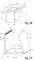
- Figure 26 also shows a practical application of the invention, more particularly a table 1, wherein a base is composed of four panel-shaped elements 2a, 2b, 2c and 2d, which are connected to each other at an angle by means of mitered corner connection 3 according to the invention.
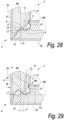
- Figure 28 shows an embodiment, not according to the claimed invention.
- this thus relates to a composed element, which comprises at least two panel-shaped elements 2a-2b, each with respective panel surfaces, wherein for each panel-shaped element a center line Ma-Mb is defined centrally between the two panel surfaces of that panel-shaped element;
- Figure 29 shows another particular variant, not according to the claimed invention.
- the tongue 8 consists of a split tongue, wherein the slit 12, globally seen and/or with the wall thereof which is situated closest to the inner corner, from the free end, in other words, open end thereof extends towards the bottom inclined towards the panel surface which is located at the inner corner 5, such as is clearly visible here by means of the inclined axis line L2.
- the flexibility of the tongue portion which comprises the locking element 10 can be adjusted in an easy manner by letting the slit end closer or less close to the respective panel surface.
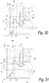
- Figure 30 represents a particular embodiment, not according to the claimed invention.
- the groove 9, at least at one side thereof, seen in cross-section, is bordered by a lip 16 which is located at least with a portion 29 thereof beyond said theoretical miter line L1, and this lip 16, in coupled condition, is located at the side of the tongue 8 which is situated closest to the formed outer corner 4, and this in such a manner that the aforementioned portion 29 provides at least a contact surface 17 for the tongue 8.
- a good lateral support is offered for the tongue.
- the protruding edge portion 31, next to its distal end 32, comprises a locking part 33, which, in coupled condition, engages behind the other panel-shaped element 2b, in such a manner that the relatively thin edge portion 31 is prevented from bending out due to warping.
- zone G1 does not exclude to apply identical profiles also outside of the zone G1.
- the zones G2 and G3 are made identical to each other as well, with the only difference that the portion being at 45 degrees, which is situated on the outer corner 4, extends somewhat longer. It is clear that then the same cutting tools and tool settings can be applied for the entire edge finishing.
- a “composed element” an element has to be understood which is already assembled, as well as such element which still is in disassembled condition. More particularly, this means that a piece of RTA furniture, which meets the invention and still is in disassembled condition, for example, packaged as a flat-pack piece of furniture, in this condition also has to be considered a “composed element”.
Landscapes
- Engineering & Computer Science (AREA)
- General Engineering & Computer Science (AREA)
- Mechanical Engineering (AREA)
- Life Sciences & Earth Sciences (AREA)
- Wood Science & Technology (AREA)
- Furniture Connections (AREA)
- Finishing Walls (AREA)
- Connection Of Plates (AREA)
Description
- This invention relates to a composed element consisting of at least two panel-shaped elements, as well as to a corner connection applied thereby.
- In particular, the invention relates to a composed element, which comprises at least two panel-shaped elements, which are coupled to each other or can be coupled to each other at an angle. Herein, the invention relates to any form of composed element which comprises at least two panel-shaped elements, irrespective of the field of application. It is noted that the composed elements does not have to consist exclusively nor substantially of panel-shaped elements, however, that it suffices that the panel-shaped elements possibly only form a part thereof.
- More particularly, the invention relates to panel-shaped elements, which can be coupled to each other by means of a locking tongue and groove connection, in particular by moving the panel-shaped elements laterally towards each other and by coupling them by means of a turning movement and/or snap movement to each other at an angle. Moving the panel-shaped elements laterally towards each other means that these panel-shaped elements are presented sideways to each other with their respective panel edges.
- Primarily, the present invention is intended for being applied in the furniture sector, wherein the composed element consists of a piece of furniture or of a furniture component. More particularly, the present invention can be applied for composing loose furniture as well as built-in furniture, such as, for example, kitchen furniture, dressing furniture and the like, as well as for furniture components, such as drawers. The invention is in particular suitable for being applied with furniture which is sold in dismantled condition and has to be assembled and/or installed by the buyer or possibly by an installer. This type of furniture is also known under the denomination flat pack furniture or as RTA furniture. Herein, RTA stands for "Ready To Assemble". It is noted that the present invention can also be used in any other application, such as, for example, for wall panels, storage boxes, coffins and the like.
- More particularly, the invention aims at a composed element, such as explained herein above, and a corner connection between panel-shaped elements applied hereby, which can be assembled and realized in a simple and smooth manner.
- More particularly, the invention relates to a composed element of the type which comprises two or more panel-shaped elements, which each possess coupling parts in the form of a tongue and a groove, respectively, wherein these coupling parts allow that the panel-shaped elements can be coupled to each other in a locking manner and at an angle. In this context, this is referred to as a mechanically locking coupling system, more particularly a locking tongue and groove connection. Further, this locking tongue and groove preferably are present in the form of a profile respectively extending in the longitudinal direction of the panel-shaped element. A composed element which makes use of such tongue and groove connection is known, amongst others, from
WO 2010/070605 . - Substantially, there are two types of corner connections. A first type of corner connection, in this context described as a common corner connection, relates to a connection wherein, in the longitudinal direction of the formed corner, the panel edge of one of the two panel-shaped elements coupled at an angle remains completely visible after they have been brought into the coupled condition. A second type of corner connection relates to a connection wherein the panel-shaped elements are brought together in miter at their respective panel edge. In this case, this is also called a miter coupling or a mitered corner connection. Herein, the panel edges of the two panel-shaped elements in the longitudinal direction of the formed corner are not visible or visible in a limited manner only, when they were brought into coupled condition. In certain applications, it is more desirable to work with a miter coupling instead of a common corner connection, for esthetical reasons.
- In the field of esthetics, a miter coupling has some important advantages in respect to a common corner connection. By working with a miter coupling, a more solid impression is obtained. Further, this also gives an impression of handcraft or at least of a more precise finishing of the composed element. Technically seen, by making use of a miter coupling, it is avoided or restricted that the panels have to be masked along the side of the miter coupling by means of a relatively wide masking strip, such as, for example, a laminate strip or a masking strip of synthetic material, for example, an ABS strip (Acrylonitrile-butadiene-styrene). By means of a miter coupling, the use of the masking strip can be avoided, or a narrower masking strip can be used.
- From
WO 2010/070605 , couplings are known for common corner connections as well as for mitered corner connections.WO 2010/070605 shows a profile for a mitered coupling in figure 66. -
WO2011/151758A2 discloses composed elements wherein panel-shaped elements are coupled to each other by means of a tongue and groove connection wherein a locking is established between the coupled panel-shaped elements. -
EP0479767A1 discloses miter couplings of wood-based panel-shaped elements. - The present invention aims at an improvement of, or an alternative for, the already known profile for mitered coupling from
WO 2010/070605 , wherein the coupling system preferably is improved in the field of stability and strength of the composed element, as well as in the field of ease of installation, more particularly of the joining together of the component panels. - In fact, it is clear that such couplings, during assembly or coupling as well as afterwards, are subjected to forces. These forces originate from the own weight of the composed element, as well as from possible external loads to which the composed element is subjected. Considering that the profiles, however, mostly have to be realized in relatively thin panels, and moreover typically, however, not exclusively, are made in particle board, which, as known, can be relatively brittle, it is important to perform an innovating optimization on the applied profiles.
- The present invention thus primarily aims at possibilities for optimizing such miter couplings.
- The invention is described in
claim 1. The dependent claims describe preferred embodiments of the invention. - The locking elements provided on the tongue and groove provide for that in a usual mutually coupled condition, the moving apart of the respective panel-shaped elements is counteracted. More particularly, the moving apart with a translation movement at least according to a direction of the center lines of the respective panel-shaped elements and according to a direction perpendicular to the theoretical miter line is counteracted by these locking elements.
- According to a preferred embodiment of the invention, the tongue is situated eccentric in respect to the midpoint of the theoretical miter line, such preferably in the direction of said inner corner. Due to the eccentric arrangement of the tongue, more material can be kept on the outer corner, which leads to a sturdier construction and therefore a diminished risk of a breaking-off of material portions. In the case of a panel-shaped element with a covering, such as, for example, a laminate covering, an eccentric arrangement may contribute to a better resistance against warping of the panel-shaped element at the location of the outer corner as a result of tensile stress in the covering, such that the risk of a poor connection of the panel-shaped elements on the location of the outer corner can be restricted. Tensile stresses in the covering, in the example of a laminate covering, can occur under the influence of temperature and temperature differences during and after the production process. Hardening the resin present in the laminate, for example, is accompanied by a shrinkage which is larger than the possible deformation of the underlying material of the basic board of the panel-shaped elements. Further, an eccentric arrangement of the tongue allows obtaining, during assembly, an improved turning movement of the tongue in the groove.
- According to the invention, said tongue is cut free on at least one side, preferably by means of a cut, by means of a narrow incision. By a narrow incision, an incision is meant having a depth which is larger than the width. By cutting the tongue free on at least one side, the tongue or the adjacent tongue portion can be rendered more elastic. This latter allows optimizing the coupling even further by making a compromise between the strength of the locking between two panel-shaped elements in coupled condition, on the one hand, and the force required to bring two panel-shaped elements in coupled condition, on the other hand.
- According to an embodiment of the invention, it is preferred that the tongue is cut free on one side only, preferably on the side of the tongue situated closest to the formed outer corner. By cutting the tongue free on one side only, it is prevented that the tongue would be too sensitive and becomes less resistant against breaking-off. The preference of cutting a tongue free on the side situated closest to the formed outer corner is primarily important when this characteristic is combined with an eccentric tongue, wherein the tongue is situated closer to the inner corner than to the outer corner.
- According to the invention, the aforementioned locking elements are present at the height of one side of the tongue only, whereby at the other side of the tongue, this latter is free from locking elements. This characteristic allows that the panel-shaped element having the tongue can be turned into the corresponding panel-shaped element having the groove in a beneficial manner, or in other words the respective panel-shaped elements can be turned into each other. According to a particular deviating embodiment, in fact locking elements can be present at the height of the other side of the tongue, however, these last-mentioned locking elements are less pronounced than the locking elements situated at the height of the first side of the tongue.
- According to the invention, said groove, on at least one side thereof, seen in cross-section, is bordered by a lip extending to beyond said theoretical miter line, seen from the panel-shaped element having the groove, which lip is called a protruding lip herein below. This offers the advantage that a contact surface can be formed between the tongue and the groove beyond the theoretical miter line. In coupled condition, such contact surface can provide for an improved support of the tongue and in this way contribute to an improved locking of the panel-shaped elements. In this case, as well as in the herein below described applications, the term "contact surface" has to be interpreted in its broadest sense as a zone where a contact can take place, wherein such zone, seen in cross-section, can extend over a distance as well as can consist of a local contact point.
- According to the invention, said protruding lip is located at the side which is situated closest to the formed outer corner. Further, at the height of this protruding lip at least one contact surface is formed between the tongue and the groove. In coupled condition of the panel-shaped elements, this contact surface will provide for a support of the tongue which is effective at least according to the direction perpendicular to the center line of said panel-shaped element having the tongue.
- According to still another preferred embodiment of the invention, said protruding lip in coupled condition forms two contact surfaces with the tongue which provide for a support which is effective at least according to the direction perpendicular to the center line of said panel-shaped element with said tongue.
- It is preferred that at least one of said contact surfaces is situated beyond the theoretical miter line at the side of the panel-shaped element having the tongue. This offers the advantage of offering additional strength to the formed mitered corner connection.
- It is clear that in respect to the invention, the preceding characteristics do not exclude that also on the other side of the groove, which is situated closest to the formed inner corner, a protruding lip can be present.
- More particularly, it is of interest to provide, at the side of the groove which is situated closest to the formed inner corner, a smaller protruding lip portion, wherein the panel surface of the panel-shaped element having the groove continues at the height of the inner corner beyond the theoretical miter line, seen from the panel-shaped element having the groove, as a result of which at that location a contact surface is formed which coincides with a portion of said panel surface.
- More particularly, by applying a protruding lip, a contact surface can be formed between the tongue and the groove beyond said theoretical miter line, seen from the panel-shaped element having the groove. In coupled condition, such contact surface can provide for an improved support of the tongue and in this manner contribute to an improved locking of the panel-shaped elements.
- Said protruding lip is situated at the side of the groove which is situated closest to the formed outer corner. Further, at the height of this protruding lip at least one contact surface is formed between the tongue and the groove. In coupled condition, this contact surface can provide for a support of the tongue which is effective at least according to the direction perpendicular to the center line of said panel-shaped element having the tongue.
- Said protruding lip preferably, in coupled condition, forms two contact surfaces with the tongue, which provides for a support which is effective at least according to the direction perpendicular to the center line of said panel-shaped element having the tongue.
- It is preferred that at least one of said contact surfaces is situated beyond the theoretical miter line at the side of the panel-shaped element having the tongue. This characteristic offers the advantage of offering additional strength to the formed mitered corner connection.
- It is clear that the aforementioned characteristics do not exclude that on both sides of the groove a lip can be present which extends to beyond said theoretical miter line.
- More particularly, it is of interest to provide at the side of the groove situated closest to the formed inner corner, a smaller lip, which extends to beyond the theoretical miter line, wherein the panel surface of the panel-shaped element having the groove continues at the height of the inner corner beyond the theoretical miter line, as a result of which at that location a contact surface is formed, which coincides with a portion of said panel surface.
- The invention relates to a composed element, which comprises at least two panel-shaped elements, each with respective panel surfaces, wherein for each panel-shaped element a center line is defined centrally between the two panel surfaces of that panel-shaped element; wherein said panel-shaped elements are manufactured of wood-based material; wherein said panel-shaped elements can be coupled to each other at an angle by means of a locking tongue and groove connection and hereby form an inner and outer corner, wherein the inner and outer corner define a theoretical miter line; wherein said locking tongue and groove connection respectively is formed substantially of a tongue on one of said panel-shaped elements, of a groove on another of said panel-shaped elements and of locking elements provided on said tongue and groove; wherein, seen in cross-section, the panel surface of each panel-shaped element at the side of the formed outer corner extends at least to the center line of the panel-shaped element to which it is coupled; with the characteristic that said tongue is cut free on at least one side by means of a narrow incision. By cut free is meant freed from still present surrounding material of the respective panel-shaped element. By a narrow incision, an incision is meant having a depth which is larger than the width. By cutting the tongue free on at least one side, the tongue or the adjacent tongue portion can be rendered more elastic.
- This latter allows optimizing the coupling even further in the field of the strength of the locking between two panel-shaped elements in coupled condition, on the one hand, and force required for bringing two panel-shaped elements into coupled condition, on the other hand.
- Still more particularly according to the invention, it is preferred that the tongue is cut free on one side only, preferably on the side of the tongue situated closest to the formed outer corner. By cutting the tongue free on one side only, it is prevented that the tongue would be too sensitive and less resistant against breaking-off. The preference of cutting a tongue free on the side situated closest to the formed outer corner is primarily important when this characteristic is combined with an eccentric tongue, wherein the tongue is situated closer to the inner corner.
- Below, some preferred additional characteristics of the present invention will be listed.
- The tongue and the groove have such a profile that they can be brought in a mutually coupled condition by means of a turning movement as well as a translation movement towards each other. This characteristic offers the advantage that assembling or constructing the composed element can be performed in a smooth and/or simple manner.
- According to another preferred characteristic, the tongue and groove have such a profile that they can be brought into a mutually coupled condition by means of a translation movement according to a direction which is directed inclined in respect to the center line and preferably according to the direction of the slit of the tongue or according to a direction transverse, perpendicular or approximately perpendicular to the theoretical miter line. This characteristic offers the advantage that the flexibility of the tongue is adapted to the manner in which the composing panel-shaped elements are brought together during the assembly.
- According to another preferred characteristic, the tongue and groove have such a profile that the panel-shaped elements can be brought in a stable intermediate position which differs from the final coupled condition. This stable intermediate position corresponds to a first easy locking, by which the panel-shaped elements during assembly remain coupled when released. Possibly, the panel-shaped elements can easily be loosened again starting from this intermediate position. Of course, starting from this intermediate position the panel-shaped elements can be locked further and brought in the final coupled condition.
- According to a further preferred embodiment, the tongue and/or the groove are formed by profiles which are provided in the panel-shaped elements themselves, and preferably they are realized in one piece in the respective panel-shaped element, for example, by means of a cutting treatment and/or machining treatment, such as a milling treatment. This offers the advantage that no separate elements are necessary for connecting the panel-shaped elements at an angle. Another advantage thereof consists in that such profiles can be milled into the panel-shaped elements in a simple manner and a continuous locking tongue and groove connection can be realized smoothly along the entire corner connection.
- Preferably, the tongue and/or groove are formed of the material of the basic board with which the panel-shaped element is formed. This offers an important advantage for the manner of production of the panel-shaped elements of the composed element.
- However, this does not exclude that according to a particular embodiment the locking tongue and groove connection can make use of a contact surface formed by an insert and/or of a locking element which is realized as an insert, wherein said insert respectively is provided in an edge of one of the panel-shaped elements. More specifically, such insert may consist of a strip which is movable or is provided of a movable part with a contact surface or locking portion which can cooperate with a tongue or groove formed on the other panel-shaped element, a locking element formed on the other panel-shaped element, respectively.
- According to another preferred embodiment, the composed element comprises the characteristic that the panel-shaped elements comprise one or more incisions, such as said slit in the tongue or such as said incision at one side of the tongue, wherein at least one of the aforementioned incisions is partially or entirely filled with an elastically deformable material. This characteristic of the present invention can contribute to an elasticity of the tongue or of the individual tongue portions, which elasticity is adapted to the application and to the final embodiment. Also, providing an elastically deformable material or a filler can contribute to an improved resistance of the panel-shaped elements against damage; more particularly an improved resistance against damage of the tongue profiles.
- According to a possible preferred embodiment, the composed element shows the characteristic that the panel surface of each panel-shaped element, seen in cross-section, at the side of the formed outer corner, extends up to a small distance from said outer corner, more particularly a distance smaller than 1/4 of the panel thickness of the panel-shaped element to which it is coupled, still better up to a distance smaller than 1/6 of the panel thickness of the panel-shaped element to which it is coupled. This characteristic has the advantage that the panel-shaped elements can come together at the outer corner according to a closing plane which possibly deviates from the theoretical miter line of the formed miter coupling. This allows achieving a better protection of the tongue profile. According to a possible embodiment, said panel surface extends right up to said outer corner.
- According to a possible preferred embodiment, the composed element shows the characteristic that it can receive a separately applied corner element at the height of one or more of said formed inner or outer corners. This characteristic allows giving an appropriate appearance to the composed element by working with separate corner elements, which have an appropriate appearance and/or possibly have improved mechanical features. The separately applied corner element can have a rounded shape, as a result of which the composed element adopts a rounded shape at the height of the inner and/or outer corner. The composed element may also obtain improved mechanical features at the height of the inner and/or outer corner by working with separately applied corner elements of an appropriate material, such as, for example, metal or synthetic material, more in particular, for example, a corner element substantially manufactured of rubber or stainless steel or any other appropriate material.
- According to a possible preferred embodiment, the composed element shows the characteristic that the panel surface of the panel-shaped element having a groove on the side of the formed inner corner continues at the height of this inner corner to beyond the theoretical miter line, as a result of which a contact surface is formed at this place, which coincides with a portion of said panel surface. This characteristic has the advantage that hereby the assembly of the panel-shaped elements can be simplified further, for example, in that this contact surface forms a support surface during the turning-in of the panel-shaped element having the tongue.
- According to an example not according to the invention, the composed element shows the characteristic that the panel surface of each panel-shaped element on the side of the formed outer corner, seen in cross-section, instead of extending at least to the center line of the panel-shaped element to which it is coupled, extends up to a distance from said outer corner which is smaller than 3/4 of the panel thickness of the panel-shaped element to which it is coupled.
- It is noted that in the case that a slit in the tongue is applied, the location, width, depth and orientation of this slit form degrees of freedom in the design of a composed elements and the corner connections applied therewith according to the present invention. The location, and to a certain extent the orientation, too, determine the thickness ratio between the two tongue portions formed in this manner. To this aim, the thickness of the tongue portions can be determined at the height of the theoretical miter line. This ratio can be chosen as a design parameter for the applied corner connections according to the present invention and can be optimized in function of the type of load which is expected for each panel-shaped element of the composed element. The thickness of each tongue portion in fact determines the flexibility of the respective tongue portion, whereas each tongue portion contributes to different components of the locking forces of the locking tongue and groove connection.
- The width, depth and orientation of the slit in the tongue substantially determine the flexibility of the two tongue portions. These three parameters can be applied for searching, per selected basic material of which the panel-shaped elements are composed, an optimum between the strength of the locking between two panel-shaped elements in coupled condition, on the one hand, and force required for bringing two panel-shaped elements into coupled condition. In other words, a compromise between ease of installation and stability of the finally formed composed element.
- Further, it is also noted that the width, depth and orientation of the incision on the exterior of the tongue substantially determine the flexibility of the tongue or adjacent tongue portion. These three parameters can be applied again for searching, per chosen basic material of which the panel-shaped elements are composed, an optimum between the strength of the locking, on the one hand, and the force required for bringing two elements into coupled condition.
- In an embodiment of the invention, said groove, seen in cross-section, is bordered on at least one side thereof by a lip which, at least with a portion thereof, is located beyond said theoretical miter line, and wherein this lip in coupled condition is located at the side of the tongue situated closest to the formed outer corner, with the further characteristic that said portion provides at least a contact surface for the tongue. In this manner, a robust coupling is obtained. According to possibilities subordinate thereto, which may or may not be combined with each other, the composed element further is characterized:
- in that the lip has a distal end which extends up to the plane of the panel-shaped element in which the groove is provided and which is situated on the inner corner and preferably is formed by a portion of the inner wall of the panel-shaped element;
- in that the panel which is provided with the tongue comprises a protruding edge portion which, at the exterior, provides for a prolongation of the panel surface and which is situated, at the inner side, opposite to said portion of the lip and preferably adjoining thereto, wherein this protruding edge portion extends at least up to the center line of the panel-shaped element which comprises the groove, and preferably up to the actual outer corner.
- According to a particular embodiment of the last-mentioned of said two possibilities, the protruding edge portion, in the proximity of its distal end, comprises a locking part, which in coupled condition engages behind the other panel-shaped element, by which is prevented that this edge portion can deform, for example, can warp after a certain time.
- According to a particular embodiment, the invention relates to a composed element, wherein the tongue consists of a split tongue, with a slit, which, seen in cross-section, globally extends according to a direction which deviates from the direction of the center line of the panel-shaped element on which the tongue is provided, with the further characteristic that the slit, globally seen and/or with the wall thereof situated closest to the inner corner, extends from the free end thereof towards the bottom inclined towards the panel surface which is located at the inner corner.
- The invention shows its advantages best when the material shows one or more of the following characteristics:
- the panel-shaped elements substantially consist of a basic board formed of solid wood;
- the panel-shaped elements substantially consist of a basic board formed of a wood-based pressed board, in particular a MDF, HDF or particle board;
- the panel-shaped elements are formed of melaminated board;
- the panel-shaped elements are formed of multi-layered and/or multi-part board;
- the panel-shaped elements comprise a lightweight board, possibly with edges from another material, wherein such lightweight board consists, for example, of a particle board which is at least partially composed of flax chips and/or which comprises lightweight particles, such as expanded synthetic material particles;
- the panel-shaped elements are constructed as a hollow board or as a board provided with cavities, for example, with a honeycomb core, possibly with edges from another material;
- the panel-shaped elements are constructed of a basic board with a covering, more particularly a covering of synthetic material or textile.
- By multi-layered material a panel-shaped element or panel is intended which is composed of a plurality of thin layers of a same or similar material, such as plywood board, as well as a panel which is composed of a plurality of structural layers, which are formed of a clearly different material, such as, amongst others, sandwich panels.
- It is clear that the panel-shaped elements according to the present invention, on the edges extending transverse to the longitudinal direction of the locking tongue and groove connection, can be provided with a masking strip, for example, a laminate strip or a masking strip of synthetic material, for example, an ABS strip. Hereby, the ends of the tongues and grooves in coupled condition can be hidden from view. In the case of the miter coupling according to the present invention, the masking strip can also be cut off with a miter. The cut of the masking strip then will not coincide with the contour of the profiles. Such masking is performed at the factory.
- The corner connection according to the invention can be performed, wherein, seen in cross-section, the locking tongue and groove connection shows overlapping contours. Hereby, a so-called clamping tension can be obtained. Hereby, the panels-shaped elements, in their mounted final position, can be connected to each other with a so-called pretension. Herein, the panel-shaped elements come into mutual contact on one or more places. These places are also called contact surfaces. By applying said overlapping contours, it can be provided for that the panel-shaped elements are drawn towards each other with a permanent tension at the height of these contact surfaces.
- Further characteristics of the invention will become evident from the detailed description and claims following below.
- With the intention of better showing the characteristics of the invention, hereafter, as an example without any limitative character, some preferred embodiments are described, with reference to the accompanying drawings, wherein:
-
Figure 1 in perspective represents a composed element according to the invention; -
Figure 2 only represents two panel-shaped elements, connected to each other at an angle, of the composed element offigure 1 ; -
Figure 3 , at a larger scale, represents a cross-section according to line III-III offigure 1 ; -
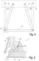
Figure 4 , in a front view, schematically represents the first steps of the assembly of the composed element offigure 1 ; -
Figure 5 , at a larger scale, represents the portion indicated by F5 infigure 4 ; -
Figure 6 represents the portion indicated by F6 infigure 4 , such during the installation of the upper panel-shaped element; -
Figures 10 to 11 ,14 to 19 and21 to 24 represent different embodiments of a corner connection also according to the present invention; -
Figures 7, 8, 9 ,12, 13 ,20 represent different embodiments of a corner connection according to the disclosure; -
Figure 25 represents a particular coupling; -
Figure 26 represents a practical application of the invention; -
Figure 27 represents three panel-shaped elements of a composed element being assembled, similar to that offigure 1 , however, provided with a masking strip; -
Figures 28 to 31 represent a number of embodiments for a corner connection in a composed element. -
Figure 1 in perspective shows a composedelement 1 according to the present invention. This relates to a possible embodiment of a composedelement 1, which in this example consists of four panel-shapedelements element 1 shown, respectively a mitered corner connection is applied between the four composing panel-shapedelements groove connection 3 with which the panel-shaped elements can be coupled to each other at an angle and hereby form anouter corner 4 and aninner corner 5, respectively. The composedelement 1 thus forms a box, wherein the panel-shapedelements - As represented in
figures 2 and3 , each panel-shaped element defines twopanel surfaces exterior surface outer corner 4 of the corner connection, and we are talking about aninterior surface inner corner 4. Mostly, as infigure 2 , too, the formedinner corner 5 between the panel-shaped elements is a right angle. However, according to the present invention, the formedinner corner 5 between the panel-shaped elements possibly may also be an angle different from 90°. Possible embodiments hereof will be described below. In most cases, the panel-shaped elements will show an equal panel thickness. However, the corner connection according to the invention can also be applied with panels of different panel thicknesses. A possible embodiment thereof will also be described herein below. Thetongue 8 andgroove 9 are made in the form of profiled panel edges. As can be seen infigure 2 , this relates to uninterruptedly continuing profiles of which thetongue 8 and thegroove 9 are composed. However, thetongue 8 and/or thegroove 9 can also be made as a discontinuous surface or possibly over only a part of an edge of the panel-shaped element. - In
figure 3 , for both panel-shapedelements element panel surfaces outer corner 4, in coupled condition define a first intersection P1. The two respective panel surfaces 7a and 7b, which are situated at the side of theinner corner 5, herein in an analogous manner in coupled condition define a second intersection P2. The aforementioned theoretical miter line L1 is formed between said two intersections P1 and P2. In some embodiments, still according to the present invention, the panel surfaces of the panel-shaped elements possibly may not continue up to the respective panel surface of the panel-shaped element to which it is coupled. In this case, a theoretical inner corner and/or a theoretical outer corner is determined by the intersection of the respective prolongations of the respective panel surfaces, and the theoretical miter line L1 is defined by this theoretical inner corner and theoretical outer corner. The aforementioned theoretical miter line L1 is represented infigure 3 by means of an axis line. - The theoretical miter angle H1 is defined as the smallest angle which extends between the theoretical miter line L1 and a perpendicular on the
panel surface 6a at the height of theouter corner 4 of the respective panel-shapedelement 2a and as shown infigure 3 . In the example offigure 3 , wherein a straight corner connection is shown, said perpendicular coincides with the center line Mb of the panel-shapedelement 2b having thegroove 9. - As represented in
figure 3 , said locking tongue andgroove connection 3 substantially consists of atongue 8 on one of the aforementioned panel-shapedelements 2a and of agroove 9 on another panel-shapedelement 2b. Further, said locking tongue andgroove connection 3 is formed by lockingelements tongue 8 andgroove 9, which locking elements, in a common mutually coupled condition of the panel-shapedelements tongue 8 andgroove 9. - Further, it is shown in this figure that, seen in cross-section, the
panel surface element outer corner 4 extends up to beyond the respective center line Mb and Ma of the panel-shapedelement figure 3 the twopanel surfaces outer corner 4, for both panel-shapedelements outer corner 4. - In the example of
figure 3 , thetongue 8 is also provided with aslit 12, as a result of which the tongue is divided into afirst tongue portion 13 and asecond tongue portion 14. - Said slit 12 in the
tongue 8 can be characterized further by an axis line L2, which, seen in cross-section and in the longitudinal direction of theslit 12 in thetongue 8, globally follows the center of thisslit 12. Herein below, this axis line L2 is denominated the axis line of the slit L2 and is shown in dashed line infigure 3 . Hereby, the axis line of the slit L2 also represents the direction of the slit in the tongue. The axis line of the slit L2 and the theoretical miter line L1 of the miter coupling also form an intersection, herein below denominated the intersection S2. Herein below, the tongue slit angle H2 is considered as being the smallest angle which is enclosed between the axis line of the slit L2 and the center line Ma of the respective panel-shapedelement 2a having thetongue 8. - In accordance with the invention, the example from
figure 3 shows the characteristic that said slit 12 globally extends according to a direction which deviates from the direction of the center line Ma of the panel-shapedelement 2a on which thetongue 8 is provided. More specifically, in the represented example said slit in thetongue 12 is directed inclined towards theinner corner 5 of the intended miter coupling. By a direction directed inclined towards theinner corner 5 must be understood that the axis line of the slit L2 extends according to a direction wherein the prolongation of the axis line of the slit L2 beyond the bottom of the slit has an intersection with thepanel surface 6a at the side of the formedouter corner 4 and thus does not have an intersection with thepanel surface 7a at the side of the formedinner corner 5. - According to a preferred characteristic of the present invention, the tongue is arranged eccentrically in respect to the intersection S1 of the center perpendicular L3 with the theoretical miter line L1, such preferably in the direction of said inner corner. For the eccentricity of the tongue, the line portion of the theoretical miter line L1 bordered by the
tongue 8 is taken into account. Infigure 3 , this line portion is represented by the line portion P3-P4 and herein below is denominated the tongue line. The points P3 and P4 are the intersections of the contour of the tongue with the theoretical miter line L1. With an eccentric arrangement of thetongue 8, the midpoint T of said tongue line P3-P4 is situated shifted in respect to the intersection S1 of the center lines Ma and Mb of the respective panel-shapedelements figure 3 , the midpoint of the tongue line P3-P4 is indicated by the point T. Preferably, said intersection S1 of the center lines Ma and Mb is situated entirely outward of said tongue line P3-P4. It is noted that for embodiments in which thetongue 8 is situated entirely along one side of the miter line L1, in other words, thetongue 8 itself does not have any intersections with the theoretical miter line L1, thetongue 8 is considered eccentric when the basis of thetongue 8 is eccentric in respect to the center line Ma of the respective panel-shapedelement 2a having thetongue 8. - The example of
figure 3 also shows the characteristic that saidtongue 8 is cut free on one side. This cutting free of thetongue 8 took place by means of anarrow incision 15. By cutting thetongue 8 free on at least one side, thetongue 8 or theadjacent tongue portion tongue 8 is cut free on only one side, here on the side of thetongue 8 which is situated closest to the formedouter corner 4. Saidincision 15 further can be characterized by an axis line L4, which, seen in cross-section and in the longitudinal direction of theincision 15, follows the middle of thisincision 15. Herein below, this axis line is called the axis line of the incision L4 and is shown in dashed line infigure 3 . Hereby, the axis line of the incision L4 also represents the direction of the incision. The orientation of the incision now can be characterized by an angle, herein denominated the incision angle H3, formed between said axis line of the incision L4 and the center line Ma, as represented infigure 3 . - The example of
figure 3 shows the characteristic that said lockingelements tongue 8, as a result of which on the other side of thetongue 8, this latter is free from locking elements. This characteristic allows that the tongue can be turned in the corresponding panel-shaped element with groove in an advantageous manner. - The example of
figure 3 also shows the characteristic, in accordance with the invention, that saidgroove 9, seen in cross-section, on the side situated closest to theouter corner 4, is bordered by a lip which extends to beyond said theoretical miter line L1, denominated the protrudinglip 16. This offers, amongst others, the advantage that acontact surface 17 can be formed between thetongue 8 and thegroove 9 beyond the theoretical miter line L1. It is clear that hereby, the embodiment offigure 3 forms an example of the invention. - The example of
figure 3 shows the characteristic of the invention that said protrudinglip 16 is located on the side which is situated closest to the formedouter corner 4. In coupled condition, said protrudinglip 16 forms twocontact surfaces element 2a having thetongue 8. - The example of
figure 3 shows the characteristic that on the side of thegroove 9 which is situated closest to the formedinner corner 5, a smallprotruding lip portion 19 is provided wherein thepanel surface 7b of the panel-shaped element having agroove 2b on the side of the formedinner corner 5, at the height of thisinner corner 5, continues to beyond the theoretical miter line L1, as a result of which acontact surface 20 is formed there, which coincides with a portion of saidpanel surface 7b. - Preferably, the panel-shaped elements have a covering on one or on both sides. Such covering may be of any kind and may be realized, for example, in the form of a laminate, for example, of the HPL type or DPL type. Other coverings are to be considered, too, such as, for example, a film, a lacquer layer, which as such may or may not be composed of a plurality of layers. It is noted that in the case of laminate coverings, when manufacturing the panel-shaped elements, preferably from the beginning it is started from a larger board which already is coated or laminated on one or both sides, from which board then the smaller panel-shaped elements will be realized. In
figure 3 , the covering 20 of the panel-shaped element is represented schematically. The thickness of the shown covering 20 does not necessarily correspond to the real thickness. Rather, the covering here is represented schematically only and, for the sake of the clarity of the figure, thicker. -
Figure 4 schematically and in front view shows the construction of the composed element offigure 1 . In this figure, it is shown how the two upright panel-shapedelements element 2b by means of substantially a rotation or turning movement, respectively. The respective panel-shapedelements groove 2b. Herein, the panel-shaped element, which is provided inclined, respectively is turned towards the final position. - In
figure 5 , at a larger scale a detail of the corner connection is represented, as indicated by reference F5 infigure 4 , wherein the two panel-shaped elements are not yet completely coupled. In this figure, it is shown that the panel-shapedelement 2a having the tongue can be turned into the corresponding panel-shaped element with groove by means of a turning movement, possibly in combination with a translation movement. - In
figure 6 is shown how, seen in cross-section, the upper panel-shapedelement 2d of the composed element offigure 1 , in a last step of the assembly, is coupled to the two upright panel-shapedelements groove 9 of the upper panel-shapedelement 2d on one side, for example, the right-hand side, over thetongue 8 of the right-hand panel-shapedelement 2c and subsequently placing theother groove 9 of the upper panel-shapedelement 2d on the other side, in this example, the left-hand side, over thetongue 8 of the left panel-shapedelement 2a. Depending on the chosen embodiment and of the geometry of thetongue 8 and thegroove 9, it is possible that the already coupled left and/or right panel-shapedelements grooves 9 of the upper panel-shapedelement 2d can be brought on both sides over therespective tongue 8 of the left and right panel-shapedelement figure 6 , a possible embodiment of this rotation is represented, wherein the panel-shapedelement 2a is brought at an assembly angle H4 in respect to the final vertical position, represented here in dotted line. Finally, the upper panel-shapedelement 2d is locked by a downward translation movement V, possibly combined with a rotational movement R3. Depending on the chosen embodiment and of the geometry of thetongue 8 andgroove 9, more or less force has to be exerted during this last downward movement V. - In
figures 10 to 11 ,14 to 19 and21 to 24 , different variants of the locking tongue and groove connection according to the present invention are shown. - In
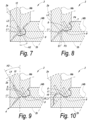
figure 7 , a locking tongue andgroove connection 3 is shown, not according to the claimed invention, wherein thetongue 8 has aslit 12, which, seen in cross-section, globally extends according to a direction which deviates from the direction of the center line Ma of the panels-shapedelement 2a on which the tongue is provided. - In
figure 8 , a variant of the locking tongue andgroove connection 3, not according to the claimed invention, is shown, with, in respect to the example offigure 7 , the additional preferred characteristic that thetongue 8 is eccentric in respect to the intersection S1 of the center perpendicular L3 with said theoretical miter line L1. For the eccentricity of the tongue, the line portion of the theoretical miter line L1, which is bordered by thetongue 8, is taken into account. Infigure 8 , this tongue is represented by the line portion P3-P4. With an eccentric arrangement of thetongue 8, the midpoint T of the tongue line is situated shifted in respect to the intersection S1. Preferably, the midpoint S1 of the theoretical miter line is located outward of said tongue line P3-P4. - In
figure 9 , a variant of the locking tongue andgroove connection 3, not according to the claimed invention, is shown, with, in respect to the example offigure 8 , the additional preferred characteristic that the tongue is cut free on one side. This cutting free of thetongue 8 took place by means of anarrow incision 15. By cutting thetongue 8 free on at least one side, thetongue 8 or theadjacent tongue portion tongue 8 is cut free at one side only, here at the side of thetongue portion 13 which is situated closest to the formedouter corner 4. Theincision 15 further is characterized by an incision angle H3, as represented infigure 9 . - In
figure 10 , a variant of the locking tongue and groove connection, according to the claimed invention, is shown, with, in respect to the example offigure 9 , the characteristic according to the invention that the groove is bordered on one side by alip 16 which extends to beyond said miter line. This lip is denominated the protrudinglip 16. This offers the advantage that acontact surface 17 between thetongue 8 and thegroove 9 can be formed beyond the theoretical miter line L1. - In
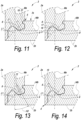
figure 11 , a variant of the locking tongue and groove connection is shown, with, in respect to the example offigure 10 , the additional preferred characteristic that thepanel surface 7b of the panel-shapedelement 2b having the groove at the side of the formedinner corner 5, continues at the height of thisinner corner 5 beyond the theoretical miter line L1, as a result of which at that location acontact surface 21 is formed, which coincides with a portion of saidpanel surface 7b. - In
figure 12 , a locking tongue andgroove connection 3 is shown, not according to the claimed invention, wherein thegroove 9 at one side is bordered by alip 16 which extends to beyond the theoretical miter line, also denominated protrudinglip 16. - In
figure 13 , a variant, not according to the claimed invention, of the locking tongue andgroove connection 3 is shown, with, in respect to the example offigure 12 , the additional preferred characteristic that the tongue has aslit 12, which, seen in cross-section, globally extends according to a direction which deviates from the direction of the center line Ma of the panel-shapedelement 2a on which the tongue is provided. - In
figure 14 , a variant, according to the claimed invention, of the locking tongue andgroove connection 3 is shown, with, in respect to the example offigure 12 , the characteristic that the tongue is cut free at one side. This cutting free of thetongue 8 took place by means of anarrow incision 15. More particularly also according to the invention, thetongue 8 is cut free at one side only, here at the side of thetongue 4 which is situated closest to the formedouter corner 4. - In
figure 15 , an example is shown, wherein, as represented schematically, particle board is used, which comprises a basic layer with coarser particles, in other words, relatively coarse chips, and which, at least on one of the sides thereof, and in this case on both sides thereof, has anouter layer 22 with particles, which in respect to average fineness have a higher degree of fineness than the particles of said basic layer. The separation between theouter layer 22 with high density and the basic layer of the panel-shaped element is indicated infigure 15 by a separation line L5 in dash-dotted line. As a particular characteristic, herein the whole is configured such that the locking surface of at least one of the locking elements 10-11, and in this case the locking surfaces of both locking elements, is, are, respectively, situated at least partially in theouter layer 22 or at least in the immediate proximity thereof. More particularly, in the example offigure 15 , the locking surface of the lockingelement 10 is situated entirely in the respectiveouter layer 22 of the respective panel-shapedelement 2a, whereas the locking surface of the lockingelement 11 is situated at a small distance from the respectiveouter layer 22 of the respective panel-shaped element 2b. Said small distance preferably is no larger than 2 millimeters. In other words, this means in the example that the distance between the locking surface of the lockingelement 11 to the closely situated separation line L5 of the panel-shapedelement 2b is not more than 2 millimeters. By situating such locking surface in such finerouter layer 22, the advantage is obtained that such locking surface is located in the most compact and stable layer, which finally will be beneficial for the strength of the coupling. Moreover, also the advantage is obtained that smoother surfaces can be created in this outer layer, which is of importance for achieving a good coupling function. When such locking surface is situated at a small distance from theouter layer 22, however, the last-mentioned advantage is no longer achieved, but the closely situatedouter layer 22 still provides for astrong locking element 11, as then still a sufficient support of the material of the basic layer will be provided. - In
figure 15 , as a particular characteristic it is also illustrated that theslit 12 is performed up to a large depth. - In
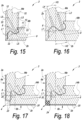
figure 16 , a locking tongue andgroove connection 3 is shown, according to the invention, wherein thetongue 8 consists of a split tongue and wherein the tongue is cut free at one side. Further, the represented example shows the characteristic that the orientation of the tongue slit and of the incision differs from the orientation of examples shown before. This illustrates the degrees of freedom which are obtained for freely choosing the orientation of the slit and the orientation of the incision and adapting them to the desired application. - In
figure 17 , a locking tongue andgroove connection 3 is shown, according to the present invention, wherein the miter coupling shows an openouter corner 4. In this embodiment, still according to the present invention, the panel surfaces 6a and 6b of the panel-shapedelements outer corner 4 is determined by the intersection of the respective prolongations of the respective panel surfaces 6a and 6b, and the theoretical miter line L1 is defined by theinner corner 5 and theoreticalouter corner 4. The openouter corner 4 can possibly be finished by means of a maskingstrip 23, such as, for example, a laminate strip or amasking strip 23 of synthetic material, for example, an ABS strip. - In
figure 18 , a locking tongue andgroove connection 3 is shown, according to the present invention, wherein the miter coupling shows an open outer corner and wherein it comprises aseparate corner element 24. It is noted that the example shown shows a covering 20 at one side of the panel-shaped elements. Of course, the covering may also be present on both sides of the panel-shaped elements. - In
figure 19 , a panel-shapedelement 2a with tongue of a locking tongue andgroove connection 3 is shown, according to the present invention, wherein the tongue slit 12 and theincision 15 are filled with an elasticallydeformable material 25. - In
figure 20 , a locking tongue andgroove connection 3 is shown, not according to the claimed invention, wherein the orientation of the tongue slit and the orientation of the incision are different. In other words, in this embodiment the tongue slit angle H2 and the incision angle H3 are different. Further, in this figure an example is given of a possible embodiment in which use is made of acontact surface 17 formed by aninsert 26 provided in the edge. More specifically, the showninsert 26 consists of a strip which is provided with amovable portion 27 withcontact surface 17, which cooperates with thetongue 8 on the other panel-shapedelement 2a. According to a not represented example, the lockingelement 11, too, can be formed by an insert, whether or not in combination with theinsert 26. -
Figure 21 shows a possible embodiment, according to the claimed invention, wherein thepanel surface 6a of the panel-shaped element having the tongue, which is situated at the side of the formed outer corner, does not continue up to the formedouter corner 4, but up to a certain distance X therefrom. However, this distance X is smaller than half of the panel thickness Wb of the panel-shaped element withgroove 2b to which it is coupled. -
Figure 22 shows a possible embodiment, wherein the panel-shaped elements, which are coupled to each other at an angle, have a different panel thickness. In this case, this is also called a non-perpendicular miter joint. The lower panel-shapedelement 2b has a panel thickness Wb which is smaller than the panel thickness Wa of the left-hand panel-shapedelement 2a to which it is coupled. It is noted that the miter angle H1 can be expressed as H1=arc tan (Wb/Wa). -
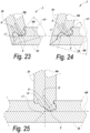
Figures 23 and 24 show possible embodiments, wherein the panel-shapedelements figure 23 , an example is shown wherein the formed angle measured at the inner corner is larger than 90°. Infigure 24 , an example is shown wherein the formed angle measured at the inner corner is smaller than 90°. - From the represented corner connections of the invention, shapes can also be derived which are suitable for forming a T-connection. An example thereof is represented in
figure 25 . -
Figure 26 also shows a practical application of the invention, more particularly a table 1, wherein a base is composed of four panel-shapedelements mitered corner connection 3 according to the invention. -
Figure 27 shows three panel-shapedelements figure 1 , however, wherein the panel-shapedelements tongue 8 or groove are present, are finished with a maskingstrip 28, which is miter-joined with the maskingstrip 28 of the respective other panel-shaped elements. -
Figure 28 shows an embodiment, not according to the claimed invention. Herein, this thus relates to a composed element, which comprises at least two panel-shapedelements 2a-2b, each with respective panel surfaces, wherein for each panel-shaped element a center line Ma-Mb is defined centrally between the two panel surfaces of that panel-shaped element; - wherein said panel-shaped elements preferably are manufactured of wood-based material;
- wherein said panel-shaped elements can be coupled to each other at an angle of 90 degrees or approximately 90 degrees by means of a locking tongue and groove connection and herein respectively form an inner and outer corner, wherein the inner and outer corner define a theoretical miter line L1;
- wherein said locking tongue and groove connection substantially is formed of a
tongue 8 on one of said panel-shaped elements, of agroove 9 on another of said panel-shaped elements and of locking elements 10-11 provided on said tongue and groove, respectively; - wherein, seen in cross-section, the panel surface of each panel-shaped element at the side of the formed outer corner extends at least up to the center line of the panel-shaped element to which it is coupled; and
- wherein the tongue preferably consists of a split tongue, with thus at least a first tongue portion and a second tongue portion, as well as a
slit 12 situated there between; -
Figure 29 shows another particular variant, not according to the claimed invention. Herein, this relates to a composed element, wherein thetongue 8 consists of a split tongue, wherein theslit 12, globally seen and/or with the wall thereof which is situated closest to the inner corner, from the free end, in other words, open end thereof extends towards the bottom inclined towards the panel surface which is located at theinner corner 5, such as is clearly visible here by means of the inclined axis line L2. Hereby, the flexibility of the tongue portion which comprises the lockingelement 10 can be adjusted in an easy manner by letting the slit end closer or less close to the respective panel surface. -
Figure 30 represents a particular embodiment, not according to the claimed invention. Herein, thegroove 9, at least at one side thereof, seen in cross-section, is bordered by alip 16 which is located at least with aportion 29 thereof beyond said theoretical miter line L1, and thislip 16, in coupled condition, is located at the side of thetongue 8 which is situated closest to the formedouter corner 4, and this in such a manner that theaforementioned portion 29 provides at least acontact surface 17 for thetongue 8. Hereby, a good lateral support is offered for the tongue. - A further particularity herein consists in that the
lip 16 has adistal end 30, which extends up to the plane of the panel-shapedelement 2b in which thegroove 8 is provided and which is situated at the inner corner and preferably is formed by a portion of the inner wall of the panel-shaped element. In other words, this means that theend 30 is formed by a portion of thepanel surface 7b. Hereby, it is obtained that thegroove 9 can be provided in theflat panel surface 7b in a simple manner. - Another particularity, which may or may not be applied in combination with the particularity described immediately herein above, consists in that the panel-shaped element which is provided with the tongue has a protruding
edge portion 31, which on the outer side provides for a prolongation of the panel surface and on the inner side is situated opposite to saidportion 29 of thelip 16 and preferably adjoining thereto, wherein this protrudingedge portion 31 extends at least up to the center line Mb of the panel-shaped element which comprises thegroove 9, and preferably up to the corner point or approximately up to the corner point of the actual outer corner. Hereby, a miter coupling is obtained with a connection near the corner point, whereas thetongue 8 as such, globally seen, can be realized approximately perpendicular to the panel-shaped element having the groove. - According to a particular characteristic, the protruding
edge portion 31, next to itsdistal end 32, comprises a lockingpart 33, which, in coupled condition, engages behind the other panel-shapedelement 2b, in such a manner that the relativelythin edge portion 31 is prevented from bending out due to warping. -
Figures 30 and 31 are represented at the same scale. The panel thickness of the panel-shaped elements offigure 30 is smaller than the panel thickness of the panel-shaped elements offigure 31 . The tongue and groove profiles which are situated in the zone G1, however, are identical to each other in respect to shape as well as to size. Adaptation takes place outside of the zones G1, thus in zone G2 or G3. In the example, this is in zone G3, by adapting the thickness of theedge portion 31 in function of the panel thickness. - However, this latter does not exclude to apply identical profiles also outside of the zone G1. In the represented example, the zones G2 and G3 are made identical to each other as well, with the only difference that the portion being at 45 degrees, which is situated on the
outer corner 4, extends somewhat longer. It is clear that then the same cutting tools and tool settings can be applied for the entire edge finishing. - In
figures 30 and 31 also a particularity is represented, which consists in that the panel-shapedelement 2a can be fixedly snapped into the panel-shapedelement 2b by means of a movement perpendicular or approximately perpendicular to this latter, such by means of aninclination 34, which can shift along the lockingelement 11. - According to a general preferred characteristic, the tongue and groove connection is made such that the panel-shaped elements can be connected to each other by means of a snap movement as well as by means of a turning movement.
- It is noted that the herein above-described panel-shaped elements according to the invention can be composed in different manners. According to a first possibility, for such panel-shaped element a wood-based single board is applied, which is manufactured of one and the same or substantially the same material, for example, a single MDF board (Medium Density Fiberboard) or HDF board (High Density Fiberboard), or a classic particle board, possibly with finer wood particles on the exterior surfaces. By a single board is meant that only one substantial structural material layer is applied, which does not exclude that other thin layers, such as coverings, can be present. Alternatively, the panel-shaped elements will consist of a multi-layered board, such as, for example, plywood boards.
- Further, it is also noted that the invention is in no way limited to cubical composed elements, but that also complete pieces of furniture, possibly with a plurality of compartments or partitions, possibly provided with shelves, drawers, doors and the like, can be provided with a respective corner connection according to the invention.
- By a "composed element", according to the invention an element has to be understood which is already assembled, as well as such element which still is in disassembled condition. More particularly, this means that a piece of RTA furniture, which meets the invention and still is in disassembled condition, for example, packaged as a flat-pack piece of furniture, in this condition also has to be considered a "composed element".
- It is clear that the invention primarily relates to furniture and furniture parts. It also relates to panel-shaped elements which comprise one or more coupling parts with which a corner connection according to the invention can be realized.
- Finally, it is also noted that said panel-shaped elements mostly are elements which cover an entire or large portion of a wall of the composed elements of which it is a part. However, in some applications, such as, for example, basic elements of a piece of kitchen furniture, more particularly, for example, the basic elements of floor units, the panel-shaped element can be provided at the height of one or more walls of the composed element as a smaller component, such as a slat. In the example of the piece of kitchen furniture, the slat typically serves as a support surface for an additional panel-shaped element, such as, for example, a worktop.
- The present invention is in no way limited to the embodiments described herein above; on the contrary, such composed elements and the respective corner connection can be realized according to various forms and dimensions, without leaving the scope of the claimed invention.
Claims (15)
- Composed element, which comprises two panel-shaped elements (2a, 2b), each with respective panel surfaces (6a, 7a, 6b, 7b), wherein for each of the two panel-shaped elements (2a, 2b) a center line (Ma, Mb) is defined centrally between the two panel surfaces (6a and 7a, 6b and 7b) of that panel-shaped element (2a, 2b);wherein said panel-shaped elements (2a, 2b) are manufactured of wood-based material;wherein said panel-shaped elements (2a, 2b) are configured such that they can be coupled to each other at an angle by means of a locking tongue and groove connection (3) and thereby respectively form a connection, an inner corner (5) and outer corner (4), wherein the inner corner (5) and outer corner (4) define a theoretical miter line (L1);wherein said locking tongue and groove connection (3) respectively is formed of a tongue (8) on one of said panel-shaped elements (2a), of a groove (9) on the other of said panel-shaped elements (2b), and of locking elements (10, 11) provided on said tongue (8) and groove (9);wherein the panel-shaped elements (2a, 2b) are configured such that they can be coupled to each other laterally and at an angle by means of a turning movement and/or a snap movement to form said connection;wherein, seen in cross-section, the panel surface (6a, 6b) of each of the two panel-shaped elements (2a, 2b) at the side of the formed outer corner (4) in the connection extends at least up to the center line (Mb, Ma) of the panel-shaped element (2b, 2a) to which it is coupled;wherein said locking elements (10, 11) are only present at the height of one side of the tongue (8);wherein said tongue (8) is cut free on at least one side by means of a narrow incision (15), wherein by a narrow incision, an incision is meant having a depth which is larger than the width; wherein by cut free is meant freed from still present surrounding material of the respective panel-shaped element;wherein said groove (9), on at least one side thereof, seen in cross-section, is bordered by a protruding lip (16) extending to beyond said theoretical miter line (L1), seen from the panel-shaped element (2b) comprising the groove (9);wherein said protruding lip (16) is located at the side which is situated closest to the formed outer corner (4);wherein at the height of this protruding lip (16) at least one contact surface (17, 18) is formed between the tongue (8) and the groove (9).
- Composed element according to claim 1, characterized in that said tongue (8) is eccentric in respect to the midpoint (S1) of said theoretical miter line (L1).
- Composed element according to claim 1 or 2, characterized in that said locking elements (10, 11) are only present at the height of the side of the tongue (8) situated closest to the inner corner (5).
- Composed element according to any of the preceding claims, characterized in that said tongue (8) is cut free on one side only, preferably on that side of the tongue (8) which is situated closest to the outer corner (4), hereby not taking into account a possible minor incision at the height of the inner corner (5).
- Composed element according to any of the preceding claims, characterized in that the tongue (8) and groove (9) have such a profile that they can be brought into a stable intermediate position which is different from the final coupled condition.
- Composed element according to any of the preceding claims, characterized in that the composed element (1) comprises one or more incisions, such as a slit (12) in the tongue or such as the aforementioned incision (15) on one side of the tongue, wherein at least one of said incisions (12, 15) is partially or entirely filled with an elastically deformable material (25).
- Composed element according to any of the preceding claims, characterized in that, seen in cross-section, the panel surface (6a, 6b) of each panel-shaped element (2a, 2b) at the side of the formed outer corner (4) extends up to a distance smaller than 1/4 of the panel thickness (Wb, Wa) of the panel-shaped element (2b, 2a) to which it is coupled, still better up to a distance smaller than 1/6 of the panel thickness (Wb, Wa) of the panel-shaped element (2b, 2a) to which it is coupled, and preferably up to said outer corner (4).
- Composed element according to any of the preceding claims, characterized in that the composed element (1), at the height of one or more of said formed inner corners (5) or outer corners (4), can receive a separately provided corner element (24).
- Composed element according to any of the preceding claims, characterized in that the panel surface (7b) of the panel-shaped element (2b) having a groove (9) at the side of the formed inner corner (5), continues at the height of this inner corner (5) to beyond the theoretical miter line (L1), as a result of which at that location a contact surface (21) is formed, which coincides with a portion of said panel surface (7b).
- Composed element according to any of the preceding claims, characterized in that instead of, seen in cross-section, the panel surface (6a, 6b) of each panel-shaped element (2a, 2b) at the side of the formed outer corner (4) extends at least up to the center line (Mb, Ma) of the panel-shaped element (2b, 2a) to which it is coupled, seen in cross-section, the panel surface (6a, 6b) of each panel-shaped element (2a, 2b) at the side of the formed outer corner (4) extends up to a distance from the formed outer corner (4) which is smaller than 3/4 of the panel thickness (Wb, Wa) of the panel-shaped element (2b, 2a) to which it is coupled.
- Composed element according to any of the preceding claims, wherein said groove (9), on at least one side thereof, seen in cross-section, is bordered by a lip (16), which, at least with a portion (29) thereof, is situated beyond said theoretical miter line (L1), and wherein said lip (16) in coupled condition is located at the side of the tongue (8) which is situated closest to the formed outer corner (4), wherein said portion provides at least a contact surface (17) for the tongue (8).
- Composed element according to claim 11, characterized in that the lip has a distal end (30), which extends to the plane of the panel-shaped element in which the groove is provided and which is located on the inner corner, and preferably is formed by a portion of the inner wall of the panel-shaped element.
- Composed element according to claim 11 or 12, characterized in that the panel which is provided with the tongue (8) has a protruding edge portion (31), which on the outer side provides for a prolongation of the panel surface and on the inner side is situated opposite to said portion (29) of the lip (16) and preferably adjoining thereto, wherein this protruding edge portion extends at least up to the center line (Mb) of the panel-shaped element which comprises the groove (9), and preferably up to the actual outer corner.
- Composed element according to any of the preceding claims, wherein the tongue (8) consists of a split tongue, with a slit (12), which, seen in cross-section, globally extends according to a direction which deviates from the direction of the center line (Ma) of the panel-shaped element on which the tongue (8) is provided, characterized in that the slit (12), globally seen and/or with the wall thereof situated closest to the inner corner, extends from the free end thereof towards the bottom inclined towards the panel surface which is located at the inner corner.
- Composed element according to any of the preceding claims, characterized in that it relates to a piece of furniture or furniture part.
Applications Claiming Priority (2)
| Application Number | Priority Date | Filing Date | Title |
|---|---|---|---|
| BE2012/0079A BE1020495A4 (en) | 2012-02-08 | 2012-02-08 | COMPOSED ELEMENT AND CORNER CONNECTION APPLIED HEREIN. |
| PCT/IB2013/051018 WO2013118075A1 (en) | 2012-02-08 | 2013-02-07 | Composed element and corner connection applied herewith |
Publications (2)
| Publication Number | Publication Date |
|---|---|
| EP2811862A1 EP2811862A1 (en) | 2014-12-17 |
| EP2811862B1 true EP2811862B1 (en) | 2025-04-09 |
Family
ID=48044958
Family Applications (1)
| Application Number | Title | Priority Date | Filing Date |
|---|---|---|---|
| EP13713518.2A Active EP2811862B1 (en) | 2012-02-08 | 2013-02-07 | Composed element and corner connection applied herewith |
Country Status (4)
| Country | Link |
|---|---|
| US (4) | US10104960B2 (en) |
| EP (1) | EP2811862B1 (en) |
| BE (1) | BE1020495A4 (en) |
| WO (1) | WO2013118075A1 (en) |
Families Citing this family (52)
| Publication number | Priority date | Publication date | Assignee | Title |
|---|---|---|---|---|
| BE1019891A5 (en) | 2011-03-28 | 2013-02-05 | Unilin Bvba | COMPOSITIONED ELEMENT AND BACK WALL CONSTRUCTION APPLIED HEREIN. |
| UA109938C2 (en) * | 2011-05-06 | 2015-10-26 | MECHANICAL LOCKING SYSTEM FOR CONSTRUCTION PANELS | |
| US9726210B2 (en) | 2013-09-16 | 2017-08-08 | Valinge Innovation Ab | Assembled product and a method of assembling the product |
| DK3047160T3 (en) | 2013-09-16 | 2019-04-08 | Vaelinge Innovation Ab | TOTAL FURNITURE PRODUCT |
| CA2933681C (en) | 2014-01-10 | 2021-10-19 | Valinge Innovation Ab | A furniture panel |
| EP3501339B1 (en) * | 2014-01-10 | 2022-11-09 | Välinge Innovation AB | An assembled product and a method of assembling the product |
| US9714672B2 (en) | 2014-01-10 | 2017-07-25 | Valinge Innovation Ab | Panels comprising a mechanical locking device and an assembled product comprising the panels |
| DE202014011293U1 (en) | 2014-02-10 | 2019-02-01 | Heinrich Ebbinghaus | Support unit for furniture |
| DE102014101600B4 (en) | 2014-02-10 | 2019-03-28 | Heinrich Ebbinghaus | Profiling and support unit for furniture |
| DE202014011271U1 (en) | 2014-02-10 | 2018-12-10 | Heinrich Ebbinghaus | Profiling for furniture |
| CN106460901B (en) | 2014-05-09 | 2020-02-04 | 瓦林格创新股份有限公司 | Mechanical locking system for building panels |
| CN107027318A (en) | 2014-07-11 | 2017-08-08 | 瓦林格创新股份有限公司 | Panel with sliding part |
| DE102014110123B4 (en) * | 2014-07-18 | 2025-04-24 | Guido Schulte | Corner connection of two components with a gap |
| DE102014110124A1 (en) * | 2014-07-18 | 2016-01-21 | Guido Schulte | Tongue and Federeckverbindung of two components under inclusion of an additional tongue and groove connector |
| USD746590S1 (en) * | 2014-10-08 | 2016-01-05 | Wax Stacks, Llc | Collapsible storage box |
| BE1022567B1 (en) | 2014-10-31 | 2016-06-07 | Unilin Bvba | Furniture |
| BR112017012422B1 (en) * | 2014-12-19 | 2022-11-08 | Vãlinge Innovation Ab | ASSEMBLY OF PANELS COMPRISING A MECHANICAL LOCKING DEVICE |
| EP3285620A4 (en) | 2015-04-21 | 2018-11-14 | Välinge Innovation AB | Panel with a slider |
| MY185635A (en) | 2015-04-30 | 2021-05-27 | Valinge Innovation Ab | Panel with a fastening device |
| UA125554C2 (en) | 2015-09-22 | 2022-04-20 | Велінге Інновейшн Аб | Panels comprising a mechanical locking device and an assembled product comprising the panels |
| LT3384165T (en) | 2015-12-03 | 2021-11-10 | Välinge Innovation AB | Set of panels comprising a mechanical locking device |
| WO2017131574A1 (en) | 2016-01-26 | 2017-08-03 | Välinge Innovation AB | Panels comprising a mechanical locking device and an assembled product comprising the panels |
| RU2724688C2 (en) | 2016-02-04 | 2020-06-25 | Велинге Инновейшн Аб | Set of panels for assembled article |
| CA3011703A1 (en) | 2016-02-09 | 2017-08-17 | Valinge Innovation Ab | Element and method for providing dismantling groove |
| CA3011612A1 (en) | 2016-02-09 | 2017-08-17 | Valinge Innovation Ab | A set of three panel-shaped elements |
| MX2018009631A (en) | 2016-02-15 | 2018-12-17 | Vaelinge Innovation Ab | A method for forming a panel for a furniture product. |
| US9826828B1 (en) * | 2016-08-01 | 2017-11-28 | David E. Vaughan, Jr. | Cabinet assembly system utilizing cooperating grooved components |
| CA3040653A1 (en) | 2016-10-27 | 2018-05-03 | Valinge Innovation Ab | Set of panels with a mechanical locking device |
| EA038797B1 (en) | 2017-05-15 | 2021-10-20 | Велинге Инновейшн Аб | Set for mechanical blocking cylindrical parts of an assembled furniture product |
| GB2567447A (en) | 2017-10-11 | 2019-04-17 | Catemario Di Quadri Francesco | Furniture Item |
| CA3086335A1 (en) | 2017-12-22 | 2019-06-27 | Valinge Innovation Ab | A set of panels, a method for assembly of the same and a locking device for a furniture product |
| EP3728869B1 (en) | 2017-12-22 | 2023-01-25 | Välinge Innovation AB | A set of panels, a method for assembly of the same and a locking device for a furniture product |
| US10895276B2 (en) * | 2018-02-20 | 2021-01-19 | Dana Automotive Systems Group, Llc | Two material joint design |
| HRP20231305T1 (en) | 2018-03-23 | 2024-02-02 | Välinge Innovation AB | SET OF PANELS |
| CN112262265B (en) | 2018-04-18 | 2022-12-20 | 瓦林格创新股份有限公司 | Symmetrical tongue and T-shaped cross assembly |
| WO2019203722A1 (en) | 2018-04-18 | 2019-10-24 | Välinge Innovation AB | Set of panels with a mechanical locking device |
| EP3781822B1 (en) | 2018-04-18 | 2024-08-21 | Välinge Innovation AB | Set of panels with a mechanical locking device |
| EP3781823B1 (en) | 2018-04-18 | 2024-04-10 | Välinge Innovation AB | Set of panels with a mechanical locking device |
| US11614114B2 (en) | 2018-04-19 | 2023-03-28 | Valinge Innovation Ab | Panels for an assembled product |
| CN108835906A (en) * | 2018-08-03 | 2018-11-20 | 合肥德懋家居有限公司 | A kind of device preventing bar desk crack |
| KR102878208B1 (en) * | 2018-08-30 | 2025-10-28 | 뵈린게 이노베이션 에이비이 | A set of panels having a mechanical locking device |
| EP4410151B1 (en) | 2018-08-30 | 2026-04-15 | Välinge Innovation AB | Set of panels with a mechanical locking device |
| CN109853356A (en) * | 2018-12-25 | 2019-06-07 | 浙江中隧桥波形钢腹板有限公司 | Quick assembled type waveform board member, corrugated sheet Rapid Combination case and its assembly method |
| KR102850011B1 (en) * | 2019-01-29 | 2025-08-26 | 빌록스 에이비 | Connecting system for furniture parts |
| EP3718437A1 (en) * | 2019-04-05 | 2020-10-07 | Välinge Innovation AB | Method for assembling a piece of furniture |
| EP3834661A1 (en) * | 2019-12-11 | 2021-06-16 | Välinge Innovation AB | Mechanical locking system for panels |
| CN118076812A (en) * | 2021-10-04 | 2024-05-24 | 瓦林格创新股份有限公司 | Mechanical connection arrangement of panels |
| IL291736A (en) * | 2022-03-27 | 2023-10-01 | Flooring Ind Ltd Sarl | Composed element and corner connection applied herewith |
| WO2023191691A1 (en) * | 2022-03-30 | 2023-10-05 | Välinge Innovation AB | Set of panels and an associated assembled article |
| WO2024084324A1 (en) * | 2022-10-20 | 2024-04-25 | Unilin, Bv | Composed element and corner connection applied herewith. |
| EP4655511A1 (en) * | 2023-01-27 | 2025-12-03 | Välinge Innovation AB | A connection arrangement for panels |
| CN116480854A (en) * | 2023-04-26 | 2023-07-25 | 江苏肯菲特新能源有限公司 | A quick-connect sealed ventilation duct |
Citations (3)
| Publication number | Priority date | Publication date | Assignee | Title |
|---|---|---|---|---|
| WO2010070605A2 (en) * | 2008-12-17 | 2010-06-24 | Unilin, Bvba | Composed element, multi-layered board and panel-shaped element for forming this composed element |
| WO2011151758A2 (en) * | 2010-06-03 | 2011-12-08 | Unilin, Bvba | Composed element and corner connection applied herewith |
| US20130071172A1 (en) * | 2010-06-03 | 2013-03-21 | Unilin, Bvba | Composed element |
Family Cites Families (8)
| Publication number | Priority date | Publication date | Assignee | Title |
|---|---|---|---|---|
| US1533099A (en) * | 1924-07-14 | 1925-04-14 | Robert E Carroll | Square-corner glue joint |
| US4099887A (en) * | 1977-07-18 | 1978-07-11 | Einhard Mackenroth | Structural joints |
| AT394252B (en) * | 1990-10-03 | 1992-02-25 | Katteneder Wolfgang | MITER CONNECTION |
| US7454875B2 (en) * | 2004-10-22 | 2008-11-25 | Valinge Aluminium Ab | Mechanical locking system for floor panels |
| US7818939B2 (en) * | 2007-06-05 | 2010-10-26 | Irvin Bearinger | Snap lock joint |
| BE1019891A5 (en) * | 2011-03-28 | 2013-02-05 | Unilin Bvba | COMPOSITIONED ELEMENT AND BACK WALL CONSTRUCTION APPLIED HEREIN. |
| UA109938C2 (en) * | 2011-05-06 | 2015-10-26 | MECHANICAL LOCKING SYSTEM FOR CONSTRUCTION PANELS | |
| TR201820039T4 (en) * | 2012-02-13 | 2019-01-21 | Unilin Bvba | Method for manufacturing a drawer. |
-
2012
- 2012-02-08 BE BE2012/0079A patent/BE1020495A4/en active
-
2013
- 2013-02-07 WO PCT/IB2013/051018 patent/WO2013118075A1/en not_active Ceased
- 2013-02-07 US US14/377,584 patent/US10104960B2/en not_active Expired - Fee Related
- 2013-02-07 EP EP13713518.2A patent/EP2811862B1/en active Active
-
2018
- 2018-10-19 US US16/165,156 patent/US10285499B2/en active Active
-
2019
- 2019-04-05 US US16/376,121 patent/US10524567B2/en active Active
- 2019-12-04 US US16/703,002 patent/US20200100585A1/en not_active Abandoned
Patent Citations (3)
| Publication number | Priority date | Publication date | Assignee | Title |
|---|---|---|---|---|
| WO2010070605A2 (en) * | 2008-12-17 | 2010-06-24 | Unilin, Bvba | Composed element, multi-layered board and panel-shaped element for forming this composed element |
| WO2011151758A2 (en) * | 2010-06-03 | 2011-12-08 | Unilin, Bvba | Composed element and corner connection applied herewith |
| US20130071172A1 (en) * | 2010-06-03 | 2013-03-21 | Unilin, Bvba | Composed element |
Also Published As
| Publication number | Publication date |
|---|---|
| EP2811862A1 (en) | 2014-12-17 |
| US10524567B2 (en) | 2020-01-07 |
| US10285499B2 (en) | 2019-05-14 |
| US10104960B2 (en) | 2018-10-23 |
| US20200100585A1 (en) | 2020-04-02 |
| US20160000220A1 (en) | 2016-01-07 |
| WO2013118075A1 (en) | 2013-08-15 |
| BE1020495A4 (en) | 2013-11-05 |
| US20190045921A1 (en) | 2019-02-14 |
| US20190231066A1 (en) | 2019-08-01 |
Similar Documents
| Publication | Publication Date | Title |
|---|---|---|
| US10524567B2 (en) | Composed element and corner connection applied herewith | |
| US12607216B2 (en) | Composed element and corner connection applied herewith | |
| EP3594514B1 (en) | Panels comprising a mechanical locking device | |
| AU2014376415B2 (en) | Panels comprising a mechanical locking device and an assembled product comprising the panels | |
| RU2580489C2 (en) | Assembled element and angular joint used in it | |
| KR102048667B1 (en) | Composed element, multi-layered board and panel-shaped element for forming this composed element | |
| EP1887910B1 (en) | Assembly between a side member and a rear panel of a piece of furniture | |
| KR101899170B1 (en) | Composed element and corner connection applied herewith | |
| EP4252585B1 (en) | Composed element | |
| ITMI20110382U1 (en) | COMPOSED ELEMENT AND ANGULAR FITTING APPLIED WITH THE SAME |
Legal Events
| Date | Code | Title | Description |
|---|---|---|---|
| PUAI | Public reference made under article 153(3) epc to a published international application that has entered the european phase |
Free format text: ORIGINAL CODE: 0009012 |
|
| 17P | Request for examination filed |
Effective date: 20140729 |
|
| AK | Designated contracting states |
Kind code of ref document: A1 Designated state(s): AL AT BE BG CH CY CZ DE DK EE ES FI FR GB GR HR HU IE IS IT LI LT LU LV MC MK MT NL NO PL PT RO RS SE SI SK SM TR |
|
| AX | Request for extension of the european patent |
Extension state: BA ME |
|
| DAX | Request for extension of the european patent (deleted) | ||
| RIN1 | Information on inventor provided before grant (corrected) |
Inventor name: DEMAN, LUC Inventor name: DEVOS, PIETER Inventor name: MAERTENS, LUC |
|
| RIN1 | Information on inventor provided before grant (corrected) |
Inventor name: DEVOS, PIETER Inventor name: DEMAN, LUC Inventor name: MAERTENS, LUC |
|
| STAA | Information on the status of an ep patent application or granted ep patent |
Free format text: STATUS: EXAMINATION IS IN PROGRESS |
|
| 17Q | First examination report despatched |
Effective date: 20200821 |
|
| RAP1 | Party data changed (applicant data changed or rights of an application transferred) |
Owner name: UNILIN, BV |
|
| RAP1 | Party data changed (applicant data changed or rights of an application transferred) |
Owner name: FLOORING INDUSTRIES LIMITED, SARL |
|
| RAP1 | Party data changed (applicant data changed or rights of an application transferred) |
Owner name: UNILIN, BV |
|
| GRAP | Despatch of communication of intention to grant a patent |
Free format text: ORIGINAL CODE: EPIDOSNIGR1 |
|
| STAA | Information on the status of an ep patent application or granted ep patent |
Free format text: STATUS: GRANT OF PATENT IS INTENDED |
|
| GRAJ | Information related to disapproval of communication of intention to grant by the applicant or resumption of examination proceedings by the epo deleted |
Free format text: ORIGINAL CODE: EPIDOSDIGR1 |
|
| STAA | Information on the status of an ep patent application or granted ep patent |
Free format text: STATUS: EXAMINATION IS IN PROGRESS |
|
| GRAP | Despatch of communication of intention to grant a patent |
Free format text: ORIGINAL CODE: EPIDOSNIGR1 |
|
| STAA | Information on the status of an ep patent application or granted ep patent |
Free format text: STATUS: GRANT OF PATENT IS INTENDED |
|
| INTG | Intention to grant announced |
Effective date: 20241025 |
|
| INTC | Intention to grant announced (deleted) | ||
| INTG | Intention to grant announced |
Effective date: 20241115 |
|
| RIN1 | Information on inventor provided before grant (corrected) |
Inventor name: DEMAN, LUC Inventor name: MAERTENS, LUC Inventor name: DEVOS, PIETER |
|
| GRAS | Grant fee paid |
Free format text: ORIGINAL CODE: EPIDOSNIGR3 |
|
| GRAA | (expected) grant |
Free format text: ORIGINAL CODE: 0009210 |
|
| STAA | Information on the status of an ep patent application or granted ep patent |
Free format text: STATUS: THE PATENT HAS BEEN GRANTED |
|
| P01 | Opt-out of the competence of the unified patent court (upc) registered |
Free format text: CASE NUMBER: APP_7067/2025 Effective date: 20250211 |
|
| AK | Designated contracting states |
Kind code of ref document: B1 Designated state(s): AL AT BE BG CH CY CZ DE DK EE ES FI FR GB GR HR HU IE IS IT LI LT LU LV MC MK MT NL NO PL PT RO RS SE SI SK SM TR |
|
| REG | Reference to a national code |
Ref country code: GB Ref legal event code: FG4D |
|
| REG | Reference to a national code |
Ref country code: CH Ref legal event code: EP |
|
| REG | Reference to a national code |
Ref country code: DE Ref legal event code: R096 Ref document number: 602013086655 Country of ref document: DE |
|
| REG | Reference to a national code |
Ref country code: IE Ref legal event code: FG4D |
|
| REG | Reference to a national code |
Ref country code: NL Ref legal event code: MP Effective date: 20250409 |
|
| PG25 | Lapsed in a contracting state [announced via postgrant information from national office to epo] |
Ref country code: NL Free format text: LAPSE BECAUSE OF FAILURE TO SUBMIT A TRANSLATION OF THE DESCRIPTION OR TO PAY THE FEE WITHIN THE PRESCRIBED TIME-LIMIT Effective date: 20250409 |
|
| REG | Reference to a national code |
Ref country code: AT Ref legal event code: MK05 Ref document number: 1782707 Country of ref document: AT Kind code of ref document: T Effective date: 20250409 |
|
| PG25 | Lapsed in a contracting state [announced via postgrant information from national office to epo] |
Ref country code: FI Free format text: LAPSE BECAUSE OF FAILURE TO SUBMIT A TRANSLATION OF THE DESCRIPTION OR TO PAY THE FEE WITHIN THE PRESCRIBED TIME-LIMIT Effective date: 20250409 Ref country code: ES Free format text: LAPSE BECAUSE OF FAILURE TO SUBMIT A TRANSLATION OF THE DESCRIPTION OR TO PAY THE FEE WITHIN THE PRESCRIBED TIME-LIMIT Effective date: 20250409 Ref country code: PT Free format text: LAPSE BECAUSE OF FAILURE TO SUBMIT A TRANSLATION OF THE DESCRIPTION OR TO PAY THE FEE WITHIN THE PRESCRIBED TIME-LIMIT Effective date: 20250811 |
|
| REG | Reference to a national code |
Ref country code: LT Ref legal event code: MG9D |
|
| PG25 | Lapsed in a contracting state [announced via postgrant information from national office to epo] |
Ref country code: GR Free format text: LAPSE BECAUSE OF FAILURE TO SUBMIT A TRANSLATION OF THE DESCRIPTION OR TO PAY THE FEE WITHIN THE PRESCRIBED TIME-LIMIT Effective date: 20250710 Ref country code: NO Free format text: LAPSE BECAUSE OF FAILURE TO SUBMIT A TRANSLATION OF THE DESCRIPTION OR TO PAY THE FEE WITHIN THE PRESCRIBED TIME-LIMIT Effective date: 20250709 |
|
| PG25 | Lapsed in a contracting state [announced via postgrant information from national office to epo] |
Ref country code: PL Free format text: LAPSE BECAUSE OF FAILURE TO SUBMIT A TRANSLATION OF THE DESCRIPTION OR TO PAY THE FEE WITHIN THE PRESCRIBED TIME-LIMIT Effective date: 20250409 |
|
| PG25 | Lapsed in a contracting state [announced via postgrant information from national office to epo] |
Ref country code: BG Free format text: LAPSE BECAUSE OF FAILURE TO SUBMIT A TRANSLATION OF THE DESCRIPTION OR TO PAY THE FEE WITHIN THE PRESCRIBED TIME-LIMIT Effective date: 20250409 |
|
| PG25 | Lapsed in a contracting state [announced via postgrant information from national office to epo] |
Ref country code: HR Free format text: LAPSE BECAUSE OF FAILURE TO SUBMIT A TRANSLATION OF THE DESCRIPTION OR TO PAY THE FEE WITHIN THE PRESCRIBED TIME-LIMIT Effective date: 20250409 |
|
| PG25 | Lapsed in a contracting state [announced via postgrant information from national office to epo] |
Ref country code: AT Free format text: LAPSE BECAUSE OF FAILURE TO SUBMIT A TRANSLATION OF THE DESCRIPTION OR TO PAY THE FEE WITHIN THE PRESCRIBED TIME-LIMIT Effective date: 20250409 |
|
| PG25 | Lapsed in a contracting state [announced via postgrant information from national office to epo] |
Ref country code: RS Free format text: LAPSE BECAUSE OF FAILURE TO SUBMIT A TRANSLATION OF THE DESCRIPTION OR TO PAY THE FEE WITHIN THE PRESCRIBED TIME-LIMIT Effective date: 20250709 |
|
| PG25 | Lapsed in a contracting state [announced via postgrant information from national office to epo] |
Ref country code: IS Free format text: LAPSE BECAUSE OF FAILURE TO SUBMIT A TRANSLATION OF THE DESCRIPTION OR TO PAY THE FEE WITHIN THE PRESCRIBED TIME-LIMIT Effective date: 20250809 |
|
| PG25 | Lapsed in a contracting state [announced via postgrant information from national office to epo] |
Ref country code: LV Free format text: LAPSE BECAUSE OF FAILURE TO SUBMIT A TRANSLATION OF THE DESCRIPTION OR TO PAY THE FEE WITHIN THE PRESCRIBED TIME-LIMIT Effective date: 20250409 |
|
| REG | Reference to a national code |
Ref country code: DE Ref legal event code: R097 Ref document number: 602013086655 Country of ref document: DE |
|
| PG25 | Lapsed in a contracting state [announced via postgrant information from national office to epo] |
Ref country code: DK Free format text: LAPSE BECAUSE OF FAILURE TO SUBMIT A TRANSLATION OF THE DESCRIPTION OR TO PAY THE FEE WITHIN THE PRESCRIBED TIME-LIMIT Effective date: 20250409 Ref country code: SM Free format text: LAPSE BECAUSE OF FAILURE TO SUBMIT A TRANSLATION OF THE DESCRIPTION OR TO PAY THE FEE WITHIN THE PRESCRIBED TIME-LIMIT Effective date: 20250409 |
|
| PG25 | Lapsed in a contracting state [announced via postgrant information from national office to epo] |
Ref country code: CZ Free format text: LAPSE BECAUSE OF FAILURE TO SUBMIT A TRANSLATION OF THE DESCRIPTION OR TO PAY THE FEE WITHIN THE PRESCRIBED TIME-LIMIT Effective date: 20250409 |
|
| PG25 | Lapsed in a contracting state [announced via postgrant information from national office to epo] |
Ref country code: EE Free format text: LAPSE BECAUSE OF FAILURE TO SUBMIT A TRANSLATION OF THE DESCRIPTION OR TO PAY THE FEE WITHIN THE PRESCRIBED TIME-LIMIT Effective date: 20250409 |
|
| PG25 | Lapsed in a contracting state [announced via postgrant information from national office to epo] |
Ref country code: SK Free format text: LAPSE BECAUSE OF FAILURE TO SUBMIT A TRANSLATION OF THE DESCRIPTION OR TO PAY THE FEE WITHIN THE PRESCRIBED TIME-LIMIT Effective date: 20250409 Ref country code: RO Free format text: LAPSE BECAUSE OF FAILURE TO SUBMIT A TRANSLATION OF THE DESCRIPTION OR TO PAY THE FEE WITHIN THE PRESCRIBED TIME-LIMIT Effective date: 20250409 |
|
| PG25 | Lapsed in a contracting state [announced via postgrant information from national office to epo] |
Ref country code: IT Free format text: LAPSE BECAUSE OF FAILURE TO SUBMIT A TRANSLATION OF THE DESCRIPTION OR TO PAY THE FEE WITHIN THE PRESCRIBED TIME-LIMIT Effective date: 20250409 |
|
| PLBE | No opposition filed within time limit |
Free format text: ORIGINAL CODE: 0009261 |
|
| STAA | Information on the status of an ep patent application or granted ep patent |
Free format text: STATUS: NO OPPOSITION FILED WITHIN TIME LIMIT |
|
| REG | Reference to a national code |
Ref country code: CH Ref legal event code: L10 Free format text: ST27 STATUS EVENT CODE: U-0-0-L10-L00 (AS PROVIDED BY THE NATIONAL OFFICE) Effective date: 20260218 |
|
| 26N | No opposition filed |
Effective date: 20260112 |
|
| PGFP | Annual fee paid to national office [announced via postgrant information from national office to epo] |
Ref country code: DE Payment date: 20260227 Year of fee payment: 14 |