EP2811863B1 - Bürostuhl mit einstellbarer lendenstütze - Google Patents
Bürostuhl mit einstellbarer lendenstütze Download PDFInfo
- Publication number
- EP2811863B1 EP2811863B1 EP13746406.1A EP13746406A EP2811863B1 EP 2811863 B1 EP2811863 B1 EP 2811863B1 EP 13746406 A EP13746406 A EP 13746406A EP 2811863 B1 EP2811863 B1 EP 2811863B1
- Authority
- EP
- European Patent Office
- Prior art keywords
- seat
- wire
- lumbar support
- backrest
- sheath
- Prior art date
- Legal status (The legal status is an assumption and is not a legal conclusion. Google has not performed a legal analysis and makes no representation as to the accuracy of the status listed.)
- Not-in-force
Links
Images


Classifications
-
- A—HUMAN NECESSITIES
- A47—FURNITURE; DOMESTIC ARTICLES OR APPLIANCES; COFFEE MILLS; SPICE MILLS; SUCTION CLEANERS IN GENERAL
- A47C—CHAIRS; SOFAS; BEDS
- A47C7/00—Parts, details, or accessories of chairs or stools
- A47C7/36—Supports for the head or the back
- A47C7/40—Supports for the head or the back for the back
- A47C7/46—Supports for the head or the back for the back with special, e.g. adjustable, lumbar region support profile; "Ackerblom" profile chairs
- A47C7/462—Supports for the head or the back for the back with special, e.g. adjustable, lumbar region support profile; "Ackerblom" profile chairs adjustable by mechanical means
-
- A—HUMAN NECESSITIES
- A47—FURNITURE; DOMESTIC ARTICLES OR APPLIANCES; COFFEE MILLS; SPICE MILLS; SUCTION CLEANERS IN GENERAL
- A47C—CHAIRS; SOFAS; BEDS
- A47C1/00—Chairs adapted for special purposes
- A47C1/02—Reclining or easy chairs
- A47C1/031—Reclining or easy chairs having coupled concurrently adjustable supporting parts
- A47C1/032—Reclining or easy chairs having coupled concurrently adjustable supporting parts the parts being movably-coupled seat and back-rest
-
- A—HUMAN NECESSITIES
- A47—FURNITURE; DOMESTIC ARTICLES OR APPLIANCES; COFFEE MILLS; SPICE MILLS; SUCTION CLEANERS IN GENERAL
- A47C—CHAIRS; SOFAS; BEDS
- A47C1/00—Chairs adapted for special purposes
- A47C1/02—Reclining or easy chairs
- A47C1/031—Reclining or easy chairs having coupled concurrently adjustable supporting parts
- A47C1/032—Reclining or easy chairs having coupled concurrently adjustable supporting parts the parts being movably-coupled seat and back-rest
- A47C1/03255—Reclining or easy chairs having coupled concurrently adjustable supporting parts the parts being movably-coupled seat and back-rest with a central column, e.g. rocking office chairs
-
- A—HUMAN NECESSITIES
- A47—FURNITURE; DOMESTIC ARTICLES OR APPLIANCES; COFFEE MILLS; SPICE MILLS; SUCTION CLEANERS IN GENERAL
- A47C—CHAIRS; SOFAS; BEDS
- A47C7/00—Parts, details, or accessories of chairs or stools
- A47C7/36—Supports for the head or the back
- A47C7/40—Supports for the head or the back for the back
- A47C7/46—Supports for the head or the back for the back with special, e.g. adjustable, lumbar region support profile; "Ackerblom" profile chairs
-
- A—HUMAN NECESSITIES
- A47—FURNITURE; DOMESTIC ARTICLES OR APPLIANCES; COFFEE MILLS; SPICE MILLS; SUCTION CLEANERS IN GENERAL
- A47C—CHAIRS; SOFAS; BEDS
- A47C7/00—Parts, details, or accessories of chairs or stools
- A47C7/36—Supports for the head or the back
- A47C7/40—Supports for the head or the back for the back
- A47C7/48—Supports for the head or the back for the back of freely-rotatable type
Definitions
- the present invention relates to an office chair with an adaptable lumbar support.
- a lumbar support is activated for supporting the lumbar back portion of a person seated on the chair when said person is leaning forward.
- This chair offers support for the everyday working position for persons working in an office.
- the actuator device To be able to generate forces high enough to overcome the resistance given by the lumbar support, the padding and the fabric in the backrest, when the lumbar support is adjusted from the inactive position to the fully active position, the actuator device will have a complex structure and will hence be expensive.
- An object of the invention is to provide a chair with an adaptable lumbar support that easily can be adjusted between the inactive position and the fully active position and that can be manufactured at a low cost.
- the above-mentioned object is achieved by the present invention according to the claim 1.
- the invention relates to an office chair comprising a seat, a backrest including a lumbar support, an actuator device arranged to enable adjustment of the lumbar support between an inactive position in which it follows the general shape of the backrest, and a fully active position in which it is adjusted outwards forwardly from the backrest in order to support the lumbar back portion of a person seated.
- the lumbar support comprises of a first part with a first end and a second end and a second part with a first end and a second end, said first ends of said first and second parts are connected to each other via a pivoting point and said second ends are pivotally connected to the backrest, wherein at least one of said second ends of said parts is slidably arranged along the backrest wherein the actuator device is arranged to push and/or pull said slidable ends in response to actuation.
- the lumbar support will give less resistance when adjusted between an inactive position to a fully active position resulting in a more simple structure than previously known chairs with a lumbar support, and hence it can be manufactured at a lower cost than before.
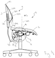
- FIG. 1 and 2 shows the general function of the office chair according to the shown embodiment of the invention.
- the office chair 1 comprises a seat 2 and a backrest 3.
- the backrest 3 includes a lumbar support 4, which is adjustable between an inactive position (shown in fig. 1 ) in which it follows the general shape of the backrest 3, and a fully active position (shown in fig. 2 ) in which it is adjusted outwards forwardly from the backrest 3 in order to support the lumbar back portion of a person seated on the seat 2 of the chair 1.
- the chair 1 comprises an adjustment device 8 (shown in fig. 3-7 ) to enable adjustment of the lumbar support 4.
- the adjustment device 8 is adjusted in response to tilting of the chair 1.
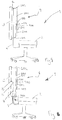
- the seat 2 is tiltable about a pivot point A between a first position or an initial position (shown in fig. 3 ), and a second slightly forwardly tilted position (shown in fig. 4 ).
- the position of the seat 2 is adjusted by means of the centre of gravity G of a person seated in the chair, such that when the centre of gravity G is located behind the first pivot point A the seat 2 is in the initial position, and when the centre of gravity G is in front of the pivot point A the seat 2 is transferred into the tilted position.
- the centre of gravity G of the person seated in the chair is represented by a chequered dot, which is to be compared with a vertical line A1 corresponding to the vertical projection of the pivot point A.
- the position of the lumbar support 4 is governed by the position of the seat 2 such that it is positioned in the inactive position (shown in fig. 3 ) when the seat 2 is in the first position, and in the active position (shown in fig. 4 ) when the seat 2 rests in the second position, in order to support the lumbar back portion of a person seated on the seat 2 of the chair 1 when said person is leaning forwards.
- This may in fact be realised in a number of ways that are obvious to a person skilled in the art once the object of the invention have been established.
- a general object of the invention is to facilitate the adjustment of the lumbar support 4.
- the lumbar support 4 comprises a first part 200 with a first end 201 and a second end 202 and a second part 300 with a first end 301 and a second end 302.
- the first end 201 of the first part 200 is connected to the first end 301 of the second part 300 via a pivoting point 400 and the second end 202 of the first part 200 and the second end 302 of the second part 300 are both pivotally coupled to the backrest 3.
- one of or both of the second ends 202, 302 of the first and second parts 200, 300, respectively, is slidably coupled to the backrest 3.
- the lumbar support also comprises a back plate 500.
- a wire 8 is arranged between the seat 2 and the lumbar support 4, a first end 12 of the wire is connected to second end 202 of the first part 200 of the lumbar support 4 and a second end 13 (se figs. 3 and 4 ) of the wire 8 is connected to the seat 2 of the chair 1.
- the second end 202 of the first part 200 of the lumbar support 4 is slidably coupled to the backrest 3 and the second end 302 of the second part 300 and the lumbar support 4 is connected to the backrest 3.
- the seat 2 pulls the first end 12 of the wire 8, which results in that the second end 13 of the wire 8 is pulling the slidable second end 202 of the first part 200 of the lumbar support 4 downwards, to position the lumbar support 4 in the active position.
- a wire 8 is arranged between the seat 2 and the lumbar support 4, a first end 12 of the wire 8 is connected to the backrest 3 and the second end 13 of the wire 8 is connected to the seat 2 of the chair 1 (se figs. 3 and 4 ).
- the second end 302 of the second part 300 of the lumbar support 4 is slidably coupled to the backrest 3 and the second end 202 of the first part 200 of the lumbar support 4 is connected to the backrest 3.
- the wire 8 is arranged inside a rigid sheath 9 such that it is free to move co-axially inside the sheath 9, wherein the sheath 9 having two openings 10, 11, through which the ends 12, 13 of the wire 8 extends.
- the wire 8 runs in a loop under the seat and said second end 13 of the wire 8 exits the second opening 11 of the sheath 9 and is attached to a fixing point 14 on a lever 40 (se fig.3 and 4 ) on the underside of the seat 2 and the first end 12 of the wire 8 exits the first opening 10 of the sheath 9 and is connected to a fixing point 15 at the backrest 3 of the chair 1.
- the function of the sheathed wire 8 is similar to the function of a shoe brake, used e.g. on bikes.
- the lever 40 When the seat 2 is tilted from the initial position, the lever 40 is arranged to be activated when the seat 2 is tilted, wherein the lever 40 pulls the second end 13 of the wire 8 so that the wire 8 successively will exit the second opening 11 of the sheath 9.
- the sheath openings 10, 11 need to restrict the sheath 9 from moving with the wire 8. The easiest way to arrange this is of course to couple the openings 10, 11 opposed to and in the vicinity of the respective fixture point 14, 15 of the wire ends 12, 13.
- the sheath 9 Since the sheath 9 is ridged and is restricted from moving with the wire 8, and the loop of the wire 8 on the underside of the seat 2 is shortened when the lever 40 pulls the second end 13 of the wire 8, the first opening 10 of the sheath 9 will move towards the first end 12 of the wire 8 and hence push the second end 302 of the slidable second part 300 of the lumber support 4 upwards, to position the lumber support 4 in the active position.
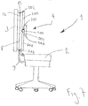
- the embodiment of the office chair 1 in fig.7 is similar to the embodiment in fig.6 , but with the difference that both the second end 202 of the first part 200 of the lumber support 4 and the second end 302 of the second part 300 of the lumber support 4 are slidably arranged in the backrest 3 and that the first end 12 of the wire 8 is coupled to said second end 202 of the first part 200 of the lumber support 4.
Landscapes
- Health & Medical Sciences (AREA)
- Dentistry (AREA)
- General Health & Medical Sciences (AREA)
- Engineering & Computer Science (AREA)
- Mechanical Engineering (AREA)
- Chairs Characterized By Structure (AREA)
- Chairs For Special Purposes, Such As Reclining Chairs (AREA)
- Chair Legs, Seat Parts, And Backrests (AREA)
- Orthopedics, Nursing, And Contraception (AREA)
Claims (8)
- Bürostuhl (1), umfassend eine Sitzfläche (2), eine Rückenlehne (3) mit einer Lendenstütze (4), eine Betätigungsvorrichtung (8), die dazu angeordnet ist, eine Einstellung der Lendenstütze (4) zwischen einer inaktiven Stellung, in der sie der allgemeinen Form der Rückenlehne (3) folgt, und einer vollständig aktiven Stellung zu ermöglichen, in der sie vorwärts von der Rückenlehne (3) nach außen eingestellt ist, um den Lendenrückenabschnitt einer Person abzustützen, die auf der Sitzfläche (2) sitzt, wobei die Lendenstütze (4) aus einem ersten Teil (200) mit einem ersten Ende (201) und einem zweiten Ende (202) und einem zweiten Teil (300) mit einem ersten Ende (301) und einem zweiten Ende (302) gebildet ist, wobei die ersten Enden (201, 301) des ersten und zweiten Teils (200, 300) über einen Drehpunkt (400) miteinander verbunden sind, und
die zweiten Enden (202, 302) drehbar an die Rückenlehne (3) gekoppelt sind, wobei wenigstens eins der zweiten Enden (202, 302) der Teile (200, 300) an der Rückenlehne (3) verschiebbar angeordnet ist, wobei die Betätigungsvorrichtung (8) ein Mittel zum Drücken und/oder Ziehen der verschiebbaren Enden (202, 302) in Reaktion auf Betätigung umfasst, um eine Gleitbewegung der verschiebbaren Enden (202, 302) zu bewirken, dadurch gekennzeichnet, dass die Sitzfläche (2) zwischen einer Ausgangsstellung und einer leicht nach vorne geneigten Stellung kippbar ist, wobei die Betätigungsvorrichtung (8) dazu angepasst ist, das Drücken und/oder Ziehen an dem wenigstens einen Ende (202, 302) in Reaktion auf das Kippen des Sitzes zu bewirken. - Bürostuhl nach Anspruch 1, dadurch gekennzeichnet, dass die Stellung der Sitzfläche (2) mittels des Körperschwerpunkts (G) einer Person einstellbar ist, die auf dem Stuhl sitzt, und dass die Stellung der Lendenstütze (4) von der Stellung der Sitzfläche (2) bestimmt wird, derart, dass sie in der inaktiven Stellung positioniert ist, wenn die Sitzfläche (2) in der Ausgangsstellung ist, und in der aktiven Stellung, wenn die Sitzfläche (2) in der gekippten Stellung ruht, um den Lendenrückenabschnitt einer Person zu stützen, die auf der Sitzfläche (2) des Stuhls (1) sitzt, wenn sich die Person nach vorne lehnt.
- Bürostuhl nach einem der vorangehenden Ansprüche, dadurch gekennzeichnet, dass die Betätigungsvorrichtung (8) ein Draht (8) mit einem zweiten Ende (13), das mit der Unterseite der Sitzfläche (2) verbunden ist, und einem ersten Ende (12) ist, das mit dem zweiten Ende (202) des ersten Teils (200) der Lendenstütze (4) verbunden ist, wobei das zweite Ende (202) des ersten Teils (200) verschiebbar in der Rückenlehne (3) gekoppelt ist und das zweite Ende (302) des zweiten Teils (300) in der Rückenlehne (3) verbunden ist, um eine Einstellung der Lendenstütze (4) zwischen der inaktiven Stellung und der vollständig aktiven Stellung zu ermöglichen, und wobei das erste Ende (12) des Drahtes (8) herabgezogen wird, wenn die Sitzfläche (2) in die gekippte Stellung gekippt wird, was bewirkt, dass das erste Ende (12) des Drahtes (8) auf die Lendenstütze (4) einwirkt, um sie in der aktiven Stellung zu positionieren.
- Bürostuhl nach Anspruch 1 oder 2, dadurch gekennzeichnet, dass sowohl 15 das zweite Ende (202) des ersten Teils (200) als auch das zweite Ende (302) des zweiten Teils (300) der Lendenstütze (4) verschiebbar in der Rückenlehne (3) angeordnet sind und dass die Betätigungsvorrichtung ein Draht (8) ist, der im Inneren einer starren Hülse (9) angeordnet ist, derart, dass er sich in der Hülse (9) frei koaxial bewegen kann, wobei die Hülse (9) zwei Öffnungen (10, 11) aufweist, eine zweite Öffnung (11), aus der ein zweites Ende (13) des Drahtes (8) austritt und sich mit einem Hebel (40) an der Unterseite des Stuhls (2) verbindet, und eine erste Öffnung (10), aus der ein erstes Ende (12) des Drahts (8) austritt und sich mit dem zweiten Ende (202) des ersten Teils (200) der Lendenstütze (4) verbindet, wobei der Draht (8) und die Hülse (9) in einer Schleife unter der Sitzfläche (2) verlaufen, und wenn der Hebel (40) den Draht (8) zieht, während die Sitzfläche (2) in die gekippte Stellung gekippt wird, die zweite Öffnung (11) der Hülse (9) vom zweiten Ende (13) des Drahts (8) fort gedrückt wird, was dazu führt, dass die erste Öffnung (10) der Hülse (9) auf das zweite Ende (302) des zweiten Teils (300) der Lendenstütze (4) einwirkt und das erste Ende (12) des Drahts (8) auf das zweite Ende (202) des ersten Teils (200) der Lendenstütze (4) einwirkt, um die Lendenstütze (4) in der aktiven Stellung zu positionieren.
- Bürostuhl nach Anspruch 1 oder 2, dadurch gekennzeichnet, dass das zweite Ende (302) des zweiten Teils (300) der Lendenstütze (4) verschiebbar in der Rückenlehne (3) angeordnet ist und dass die Betätigungsvorrichtung ein Draht (8) ist, der im Inneren einer starren Hülse (9) angeordnet ist, derart, dass er sich in der Hülse (9) frei koaxial bewegen kann, wobei die Hülse (9) zwei Öffnungen (10, 11) aufweist, eine zweite Öffnung (11), aus der ein zweites Ende (13) des Drahtes (8) austritt und sich mit einem Hebel (40) an der Unterseite des Stuhls (2) verbindet, und eine erste Öffnung (11), aus der ein erstes Ende (12) des Drahts (8) austritt und sich mit einem Befestigungspunkt (15) an der Rückenlehne (3) verbindet, wobei der Draht (8) und die Hülse (9) in einer Schleife unter der Sitzfläche (2) verlaufen, und wobei der Hebel (40) den Draht (8) zieht, während die Sitzfläche (2) in die gekippte Stellung gekippt wird, die zweite Öffnung (11) der Hülse (9) vom zweiten Ende (13) des Drahts (8) fort gedrückt wird, was dazu führt, dass die erste Öffnung (10) der Hülse (9) auf das zweite Ende (302) des zweiten Teils (300) der Lendenstütze (4) einwirkt, um die Lendenstütze (4) in der aktiven Stellung zu positionieren.
- Bürostuhl nach einem der vorangehenden Ansprüche, dadurch gekennzeichnet, dass die Lendenstütze (4) mit einer Rückenplatte (500) versehen ist, um den Rücken einer Person abzustützen, die in der aktiven Stellung auf dem Stuhl (1) sitzt.
- Bürostuhl nach einem der vorangehenden Ansprüche, dadurch gekennzeichnet, dass Kippen der Sitzfläche (2) beschränkt ist, derart, dass es dazu angepasst ist, maximal um 10°, vorzugsweise um 5° zu kippen.
- Bürostuhl nach einem der vorangehenden Ansprüche, dadurch gekennzeichnet, dass die Sitzfläche (2) des Stuhls (1) in die Ausgangsstellung vorgespannt ist.
Applications Claiming Priority (2)
| Application Number | Priority Date | Filing Date | Title |
|---|---|---|---|
| SE1250084A SE536454C2 (sv) | 2012-02-06 | 2012-02-06 | Kontorsstol med ett justerbart ländryggsstöd |
| PCT/SE2013/050097 WO2013119172A1 (en) | 2012-02-06 | 2013-02-06 | Office chair with an adaptable lumbar support |
Publications (3)
| Publication Number | Publication Date |
|---|---|
| EP2811863A1 EP2811863A1 (de) | 2014-12-17 |
| EP2811863A4 EP2811863A4 (de) | 2015-10-21 |
| EP2811863B1 true EP2811863B1 (de) | 2016-09-21 |
Family
ID=48947827
Family Applications (1)
| Application Number | Title | Priority Date | Filing Date |
|---|---|---|---|
| EP13746406.1A Not-in-force EP2811863B1 (de) | 2012-02-06 | 2013-02-06 | Bürostuhl mit einstellbarer lendenstütze |
Country Status (5)
| Country | Link |
|---|---|
| US (1) | US9351580B2 (de) |
| EP (1) | EP2811863B1 (de) |
| CN (1) | CN104244773B (de) |
| SE (1) | SE536454C2 (de) |
| WO (1) | WO2013119172A1 (de) |
Families Citing this family (1)
| Publication number | Priority date | Publication date | Assignee | Title |
|---|---|---|---|---|
| US9357849B2 (en) * | 2013-10-10 | 2016-06-07 | James E. Grove | Dynamic lumbar support for a chair |
Family Cites Families (13)
| Publication number | Priority date | Publication date | Assignee | Title |
|---|---|---|---|---|
| US5088790A (en) * | 1990-05-21 | 1992-02-18 | Lear Seating Corporation | Adjustable lumbar support mechanism for a vehicular seat |
| US5553919A (en) | 1994-10-11 | 1996-09-10 | Excellence Lumbar Corporation | Scissor jack lumbar support |
| IT1280437B1 (it) * | 1995-07-19 | 1998-01-20 | Lear Seating Italia Spa | Sedile di autoveicolo |
| US5806927A (en) * | 1997-04-11 | 1998-09-15 | American Components, Inc. | Adjustable lumbar seat support |
| US6805405B2 (en) * | 2001-03-19 | 2004-10-19 | Sung Yong Co., Ltd. | Chair equipped with lumbar support unit |
| US6695402B2 (en) | 2002-03-29 | 2004-02-24 | Paul H. Sloan, Jr. | Adjustable lumbar support |
| US7052087B2 (en) * | 2002-12-09 | 2006-05-30 | L&P Property Management Company | Method and apparatus for a scissors ergonomic support |
| KR20080037029A (ko) * | 2005-08-18 | 2008-04-29 | 가부시키가이샤 이토키 | 의자 |
| DE102006029537A1 (de) * | 2006-06-26 | 2007-12-27 | Dauphin Entwicklungs- U. Beteiligungs-Gmbh | Stuhl mit automatisch verstellbarer Lumbalstütze |
| ES2327791T3 (es) * | 2007-09-21 | 2009-11-03 | Ciar S.P.A. | Soporte lumbar. |
| JP4759767B2 (ja) * | 2008-12-08 | 2011-08-31 | 本田技研工業株式会社 | 車両のランバーサポート機構 |
| SE533354C2 (sv) * | 2009-01-29 | 2010-08-31 | Officeline Ab | Kontorsstol |
| CN102247060B (zh) * | 2011-04-08 | 2013-04-24 | 谭干荣 | 一种新型结构椅座滑行驱动靠背倾斜的座椅 |
-
2012
- 2012-02-06 SE SE1250084A patent/SE536454C2/sv not_active IP Right Cessation
-
2013
- 2013-02-06 EP EP13746406.1A patent/EP2811863B1/de not_active Not-in-force
- 2013-02-06 CN CN201380012138.7A patent/CN104244773B/zh not_active Expired - Fee Related
- 2013-02-06 US US14/376,902 patent/US9351580B2/en not_active Expired - Fee Related
- 2013-02-06 WO PCT/SE2013/050097 patent/WO2013119172A1/en not_active Ceased
Non-Patent Citations (1)
| Title |
|---|
| None * |
Also Published As
| Publication number | Publication date |
|---|---|
| EP2811863A4 (de) | 2015-10-21 |
| WO2013119172A1 (en) | 2013-08-15 |
| CN104244773A (zh) | 2014-12-24 |
| EP2811863A1 (de) | 2014-12-17 |
| US20150015041A1 (en) | 2015-01-15 |
| CN104244773B (zh) | 2017-02-22 |
| HK1200675A1 (zh) | 2015-08-14 |
| SE536454C2 (sv) | 2013-11-12 |
| US9351580B2 (en) | 2016-05-31 |
| SE1250084A1 (sv) | 2013-08-07 |
Similar Documents
| Publication | Publication Date | Title |
|---|---|---|
| US7234777B2 (en) | Chair with adjustable armrests and backrest | |
| FI110054B (fi) | Kallistettavan tuolin sovitelma | |
| US8272692B1 (en) | Office chair having tiltable seat and back | |
| EP3545795B1 (de) | Vorwärts neigemechanismus für stuhlsitz | |
| US11220342B2 (en) | Aircraft seat device | |
| US5904400A (en) | Adjustable chair | |
| KR20140013899A (ko) | 의자의 조절장치 | |
| JP2016535697A (ja) | 航空機座席用の独立的に関節運動するシートパン | |
| EP2811863B1 (de) | Bürostuhl mit einstellbarer lendenstütze | |
| US6688688B2 (en) | Chair | |
| WO2011046550A1 (en) | Adjustable armrest | |
| EP2413745B1 (de) | Bürostuhl | |
| HK1200675B (en) | Office chair with an adaptable lumbar support | |
| CN100473307C (zh) | 座椅 | |
| NO339052B1 (no) | Anordning ved sittemøbel | |
| WO2013187819A1 (en) | Lift chair for assisting user when moving between seated and standing positions | |
| US10045624B2 (en) | Lumbar support for a chair, and chair having same | |
| JP3780803B2 (ja) | 椅子 | |
| JP2026071874A (ja) | 椅子 | |
| JP5597526B2 (ja) | 腰掛け構造物のリクライニング機構 | |
| EP2559357A1 (de) | Lehnstuhl | |
| US20060138833A1 (en) | Chair control for synchronized movement of chair seat and back, and chair having same | |
| JP2006000144A (ja) | 椅子 | |
| JP2016196235A (ja) | 乗物用シート | |
| NO20140906A1 (no) | Innstilling av møbel |
Legal Events
| Date | Code | Title | Description |
|---|---|---|---|
| PUAI | Public reference made under article 153(3) epc to a published international application that has entered the european phase |
Free format text: ORIGINAL CODE: 0009012 |
|
| 17P | Request for examination filed |
Effective date: 20140820 |
|
| AK | Designated contracting states |
Kind code of ref document: A1 Designated state(s): AL AT BE BG CH CY CZ DE DK EE ES FI FR GB GR HR HU IE IS IT LI LT LU LV MC MK MT NL NO PL PT RO RS SE SI SK SM TR |
|
| AX | Request for extension of the european patent |
Extension state: BA ME |
|
| DAX | Request for extension of the european patent (deleted) | ||
| REG | Reference to a national code |
Ref country code: HK Ref legal event code: DE Ref document number: 1200675 Country of ref document: HK |
|
| RA4 | Supplementary search report drawn up and despatched (corrected) |
Effective date: 20150917 |
|
| RIC1 | Information provided on ipc code assigned before grant |
Ipc: A47C 7/46 20060101AFI20150911BHEP Ipc: A47C 7/48 20060101ALI20150911BHEP Ipc: A47C 1/032 20060101ALI20150911BHEP |
|
| GRAP | Despatch of communication of intention to grant a patent |
Free format text: ORIGINAL CODE: EPIDOSNIGR1 |
|
| INTG | Intention to grant announced |
Effective date: 20160704 |
|
| GRAS | Grant fee paid |
Free format text: ORIGINAL CODE: EPIDOSNIGR3 |
|
| GRAA | (expected) grant |
Free format text: ORIGINAL CODE: 0009210 |
|
| AK | Designated contracting states |
Kind code of ref document: B1 Designated state(s): AL AT BE BG CH CY CZ DE DK EE ES FI FR GB GR HR HU IE IS IT LI LT LU LV MC MK MT NL NO PL PT RO RS SE SI SK SM TR |
|
| REG | Reference to a national code |
Ref country code: GB Ref legal event code: FG4D |
|
| REG | Reference to a national code |
Ref country code: CH Ref legal event code: EP |
|
| REG | Reference to a national code |
Ref country code: AT Ref legal event code: REF Ref document number: 830329 Country of ref document: AT Kind code of ref document: T Effective date: 20161015 |
|
| REG | Reference to a national code |
Ref country code: IE Ref legal event code: FG4D |
|
| REG | Reference to a national code |
Ref country code: DE Ref legal event code: R096 Ref document number: 602013011867 Country of ref document: DE |
|
| REG | Reference to a national code |
Ref country code: NL Ref legal event code: FP |
|
| REG | Reference to a national code |
Ref country code: SE Ref legal event code: TRGR |
|
| REG | Reference to a national code |
Ref country code: LT Ref legal event code: MG4D |
|
| PG25 | Lapsed in a contracting state [announced via postgrant information from national office to epo] |
Ref country code: RS Free format text: LAPSE BECAUSE OF FAILURE TO SUBMIT A TRANSLATION OF THE DESCRIPTION OR TO PAY THE FEE WITHIN THE PRESCRIBED TIME-LIMIT Effective date: 20160921 Ref country code: FI Free format text: LAPSE BECAUSE OF FAILURE TO SUBMIT A TRANSLATION OF THE DESCRIPTION OR TO PAY THE FEE WITHIN THE PRESCRIBED TIME-LIMIT Effective date: 20160921 Ref country code: NO Free format text: LAPSE BECAUSE OF FAILURE TO SUBMIT A TRANSLATION OF THE DESCRIPTION OR TO PAY THE FEE WITHIN THE PRESCRIBED TIME-LIMIT Effective date: 20161221 Ref country code: LT Free format text: LAPSE BECAUSE OF FAILURE TO SUBMIT A TRANSLATION OF THE DESCRIPTION OR TO PAY THE FEE WITHIN THE PRESCRIBED TIME-LIMIT Effective date: 20160921 |
|
| REG | Reference to a national code |
Ref country code: AT Ref legal event code: MK05 Ref document number: 830329 Country of ref document: AT Kind code of ref document: T Effective date: 20160921 |
|
| REG | Reference to a national code |
Ref country code: FR Ref legal event code: PLFP Year of fee payment: 5 |
|
| PG25 | Lapsed in a contracting state [announced via postgrant information from national office to epo] |
Ref country code: LV Free format text: LAPSE BECAUSE OF FAILURE TO SUBMIT A TRANSLATION OF THE DESCRIPTION OR TO PAY THE FEE WITHIN THE PRESCRIBED TIME-LIMIT Effective date: 20160921 Ref country code: GR Free format text: LAPSE BECAUSE OF FAILURE TO SUBMIT A TRANSLATION OF THE DESCRIPTION OR TO PAY THE FEE WITHIN THE PRESCRIBED TIME-LIMIT Effective date: 20161222 |
|
| PG25 | Lapsed in a contracting state [announced via postgrant information from national office to epo] |
Ref country code: RO Free format text: LAPSE BECAUSE OF FAILURE TO SUBMIT A TRANSLATION OF THE DESCRIPTION OR TO PAY THE FEE WITHIN THE PRESCRIBED TIME-LIMIT Effective date: 20160921 Ref country code: EE Free format text: LAPSE BECAUSE OF FAILURE TO SUBMIT A TRANSLATION OF THE DESCRIPTION OR TO PAY THE FEE WITHIN THE PRESCRIBED TIME-LIMIT Effective date: 20160921 |
|
| PG25 | Lapsed in a contracting state [announced via postgrant information from national office to epo] |
Ref country code: ES Free format text: LAPSE BECAUSE OF FAILURE TO SUBMIT A TRANSLATION OF THE DESCRIPTION OR TO PAY THE FEE WITHIN THE PRESCRIBED TIME-LIMIT Effective date: 20160921 Ref country code: BE Free format text: LAPSE BECAUSE OF FAILURE TO SUBMIT A TRANSLATION OF THE DESCRIPTION OR TO PAY THE FEE WITHIN THE PRESCRIBED TIME-LIMIT Effective date: 20160921 Ref country code: PL Free format text: LAPSE BECAUSE OF FAILURE TO SUBMIT A TRANSLATION OF THE DESCRIPTION OR TO PAY THE FEE WITHIN THE PRESCRIBED TIME-LIMIT Effective date: 20160921 Ref country code: SM Free format text: LAPSE BECAUSE OF FAILURE TO SUBMIT A TRANSLATION OF THE DESCRIPTION OR TO PAY THE FEE WITHIN THE PRESCRIBED TIME-LIMIT Effective date: 20160921 Ref country code: SK Free format text: LAPSE BECAUSE OF FAILURE TO SUBMIT A TRANSLATION OF THE DESCRIPTION OR TO PAY THE FEE WITHIN THE PRESCRIBED TIME-LIMIT Effective date: 20160921 Ref country code: AT Free format text: LAPSE BECAUSE OF FAILURE TO SUBMIT A TRANSLATION OF THE DESCRIPTION OR TO PAY THE FEE WITHIN THE PRESCRIBED TIME-LIMIT Effective date: 20160921 Ref country code: BG Free format text: LAPSE BECAUSE OF FAILURE TO SUBMIT A TRANSLATION OF THE DESCRIPTION OR TO PAY THE FEE WITHIN THE PRESCRIBED TIME-LIMIT Effective date: 20161221 Ref country code: PT Free format text: LAPSE BECAUSE OF FAILURE TO SUBMIT A TRANSLATION OF THE DESCRIPTION OR TO PAY THE FEE WITHIN THE PRESCRIBED TIME-LIMIT Effective date: 20170123 Ref country code: CZ Free format text: LAPSE BECAUSE OF FAILURE TO SUBMIT A TRANSLATION OF THE DESCRIPTION OR TO PAY THE FEE WITHIN THE PRESCRIBED TIME-LIMIT Effective date: 20160921 Ref country code: IS Free format text: LAPSE BECAUSE OF FAILURE TO SUBMIT A TRANSLATION OF THE DESCRIPTION OR TO PAY THE FEE WITHIN THE PRESCRIBED TIME-LIMIT Effective date: 20170121 |
|
| REG | Reference to a national code |
Ref country code: DE Ref legal event code: R097 Ref document number: 602013011867 Country of ref document: DE |
|
| REG | Reference to a national code |
Ref country code: HK Ref legal event code: GR Ref document number: 1200675 Country of ref document: HK |
|
| PG25 | Lapsed in a contracting state [announced via postgrant information from national office to epo] |
Ref country code: IT Free format text: LAPSE BECAUSE OF FAILURE TO SUBMIT A TRANSLATION OF THE DESCRIPTION OR TO PAY THE FEE WITHIN THE PRESCRIBED TIME-LIMIT Effective date: 20160921 |
|
| PLBE | No opposition filed within time limit |
Free format text: ORIGINAL CODE: 0009261 |
|
| STAA | Information on the status of an ep patent application or granted ep patent |
Free format text: STATUS: NO OPPOSITION FILED WITHIN TIME LIMIT |
|
| PG25 | Lapsed in a contracting state [announced via postgrant information from national office to epo] |
Ref country code: DK Free format text: LAPSE BECAUSE OF FAILURE TO SUBMIT A TRANSLATION OF THE DESCRIPTION OR TO PAY THE FEE WITHIN THE PRESCRIBED TIME-LIMIT Effective date: 20160921 |
|
| 26N | No opposition filed |
Effective date: 20170622 |
|
| PG25 | Lapsed in a contracting state [announced via postgrant information from national office to epo] |
Ref country code: MC Free format text: LAPSE BECAUSE OF FAILURE TO SUBMIT A TRANSLATION OF THE DESCRIPTION OR TO PAY THE FEE WITHIN THE PRESCRIBED TIME-LIMIT Effective date: 20160921 |
|
| PG25 | Lapsed in a contracting state [announced via postgrant information from national office to epo] |
Ref country code: SI Free format text: LAPSE BECAUSE OF FAILURE TO SUBMIT A TRANSLATION OF THE DESCRIPTION OR TO PAY THE FEE WITHIN THE PRESCRIBED TIME-LIMIT Effective date: 20160921 |
|
| REG | Reference to a national code |
Ref country code: FR Ref legal event code: PLFP Year of fee payment: 6 |
|
| PGFP | Annual fee paid to national office [announced via postgrant information from national office to epo] |
Ref country code: NL Payment date: 20180215 Year of fee payment: 6 Ref country code: LU Payment date: 20180219 Year of fee payment: 6 |
|
| PGFP | Annual fee paid to national office [announced via postgrant information from national office to epo] |
Ref country code: DE Payment date: 20180216 Year of fee payment: 6 Ref country code: GB Payment date: 20180215 Year of fee payment: 6 Ref country code: CH Payment date: 20180219 Year of fee payment: 6 |
|
| PGFP | Annual fee paid to national office [announced via postgrant information from national office to epo] |
Ref country code: FR Payment date: 20180226 Year of fee payment: 6 Ref country code: IE Payment date: 20180213 Year of fee payment: 6 Ref country code: SE Payment date: 20180206 Year of fee payment: 6 |
|
| PG25 | Lapsed in a contracting state [announced via postgrant information from national office to epo] |
Ref country code: MT Free format text: LAPSE BECAUSE OF NON-PAYMENT OF DUE FEES Effective date: 20170206 |
|
| PG25 | Lapsed in a contracting state [announced via postgrant information from national office to epo] |
Ref country code: AL Free format text: LAPSE BECAUSE OF FAILURE TO SUBMIT A TRANSLATION OF THE DESCRIPTION OR TO PAY THE FEE WITHIN THE PRESCRIBED TIME-LIMIT Effective date: 20160921 |
|
| PG25 | Lapsed in a contracting state [announced via postgrant information from national office to epo] |
Ref country code: HU Free format text: LAPSE BECAUSE OF FAILURE TO SUBMIT A TRANSLATION OF THE DESCRIPTION OR TO PAY THE FEE WITHIN THE PRESCRIBED TIME-LIMIT; INVALID AB INITIO Effective date: 20130206 |
|
| REG | Reference to a national code |
Ref country code: DE Ref legal event code: R119 Ref document number: 602013011867 Country of ref document: DE |
|
| REG | Reference to a national code |
Ref country code: CH Ref legal event code: PL |
|
| REG | Reference to a national code |
Ref country code: SE Ref legal event code: EUG |
|
| REG | Reference to a national code |
Ref country code: NL Ref legal event code: MM Effective date: 20190301 |
|
| GBPC | Gb: european patent ceased through non-payment of renewal fee |
Effective date: 20190206 |
|
| PG25 | Lapsed in a contracting state [announced via postgrant information from national office to epo] |
Ref country code: SE Free format text: LAPSE BECAUSE OF NON-PAYMENT OF DUE FEES Effective date: 20190207 Ref country code: CY Free format text: LAPSE BECAUSE OF FAILURE TO SUBMIT A TRANSLATION OF THE DESCRIPTION OR TO PAY THE FEE WITHIN THE PRESCRIBED TIME-LIMIT Effective date: 20160921 Ref country code: LU Free format text: LAPSE BECAUSE OF NON-PAYMENT OF DUE FEES Effective date: 20190206 |
|
| REG | Reference to a national code |
Ref country code: IE Ref legal event code: MM4A |
|
| PG25 | Lapsed in a contracting state [announced via postgrant information from national office to epo] |
Ref country code: MK Free format text: LAPSE BECAUSE OF FAILURE TO SUBMIT A TRANSLATION OF THE DESCRIPTION OR TO PAY THE FEE WITHIN THE PRESCRIBED TIME-LIMIT Effective date: 20160921 |
|
| PG25 | Lapsed in a contracting state [announced via postgrant information from national office to epo] |
Ref country code: CH Free format text: LAPSE BECAUSE OF NON-PAYMENT OF DUE FEES Effective date: 20190228 Ref country code: LI Free format text: LAPSE BECAUSE OF NON-PAYMENT OF DUE FEES Effective date: 20190228 |
|
| PG25 | Lapsed in a contracting state [announced via postgrant information from national office to epo] |
Ref country code: IE Free format text: LAPSE BECAUSE OF NON-PAYMENT OF DUE FEES Effective date: 20190206 Ref country code: NL Free format text: LAPSE BECAUSE OF NON-PAYMENT OF DUE FEES Effective date: 20190301 Ref country code: GB Free format text: LAPSE BECAUSE OF NON-PAYMENT OF DUE FEES Effective date: 20190206 Ref country code: DE Free format text: LAPSE BECAUSE OF NON-PAYMENT OF DUE FEES Effective date: 20190903 |
|
| PG25 | Lapsed in a contracting state [announced via postgrant information from national office to epo] |
Ref country code: FR Free format text: LAPSE BECAUSE OF NON-PAYMENT OF DUE FEES Effective date: 20190228 |
|
| PG25 | Lapsed in a contracting state [announced via postgrant information from national office to epo] |
Ref country code: TR Free format text: LAPSE BECAUSE OF FAILURE TO SUBMIT A TRANSLATION OF THE DESCRIPTION OR TO PAY THE FEE WITHIN THE PRESCRIBED TIME-LIMIT Effective date: 20160921 |
|
| PG25 | Lapsed in a contracting state [announced via postgrant information from national office to epo] |
Ref country code: HR Free format text: LAPSE BECAUSE OF FAILURE TO SUBMIT A TRANSLATION OF THE DESCRIPTION OR TO PAY THE FEE WITHIN THE PRESCRIBED TIME-LIMIT Effective date: 20160921 |