EP2812192B1 - Ensemble de pointe à double paroi et instrument d'écriture comprenant ledit ensemble - Google Patents
Ensemble de pointe à double paroi et instrument d'écriture comprenant ledit ensemble Download PDFInfo
- Publication number
- EP2812192B1 EP2812192B1 EP12818964.4A EP12818964A EP2812192B1 EP 2812192 B1 EP2812192 B1 EP 2812192B1 EP 12818964 A EP12818964 A EP 12818964A EP 2812192 B1 EP2812192 B1 EP 2812192B1
- Authority
- EP
- European Patent Office
- Prior art keywords
- wall
- ferrule
- cap
- nib
- writing
- Prior art date
- Legal status (The legal status is an assumption and is not a legal conclusion. Google has not performed a legal analysis and makes no representation as to the accuracy of the status listed.)
- Active
Links
Images


Classifications
-
- B—PERFORMING OPERATIONS; TRANSPORTING
- B43—WRITING OR DRAWING IMPLEMENTS; BUREAU ACCESSORIES
- B43K—IMPLEMENTS FOR WRITING OR DRAWING
- B43K23/00—Holders or connectors for writing implements; Means for protecting the writing-points
- B43K23/08—Protecting means, e.g. caps
- B43K23/12—Protecting means, e.g. caps for pens
Definitions
- the invention generally relates to a nib assembly for a writing instrument and more specifically to a nib assembly having a ferrule including a double wall to prevent transfer of ink from an inner surface of a cap to a gripping surface of the ferrule.
- writing instruments include a writing nib that extends from a barrel or body.
- the writing nib is often protected from the environment by a cap when not in use.
- the cap can also prevent or minimize evaporation of the volatile compounds (most typically solvents) often found in inks from the writing nib.
- More volatile inks are often delivered by a porous or fibrous writing nib.
- Some inks may be delivered by a brush-type writing nib. Examples of such writing instruments include so called "paint brush markers" having a flexible layered writing nib that produces a brush-like stroke of ink.
- Some writing instruments have included a movable inner cap to provide a secondary seal between the cap and the writing nib.
- the movable inner cap is slidable along a longitudinal cap axis and biased towards the cap opening by a spring. While such an arrangement provides an additional seal between the movable inner cap and the ferrule, this type of arrangement greatly increases the manufacturing complexity and costs.
- US5451114 discloses a liquid applicator and cap.
- a circumferential projection on the cap engages with a corresponding groove on a cap mounting portion of the liquid applicator, so as to create an air tight seal.
- GB2262261 describes a nib and cap assembly and an associated writing instrument according to the preamble of claims 1 and 7 respectively.
- JPH0634987U describes a cap structure for a pen which is attached to a spindle to cover a pen body when storing a liquid pen.
- ink may be transferred from the writing nib to an inner cap surface and subsequently to a gripping surface (e.g., an outer surface of a ferrule or an outer surface of a barrel) when the cap is repeatedly closed and opened because the cap and the barrel may not be precisely aligned.
- a gripping surface e.g., an outer surface of a ferrule or an outer surface of a barrel
- This imprecise alignment causes the writing nib to contact an inner surface of the cap.
- ink may be transferred from the writing nib to the inner surface of the cap.
- the portion of the inner surface of the cap containing the transferred ink may eventually contact an outer surface of the ferrule.
- Ink disposed on the inner surface of the cap may then be transferred, at least in part, to the outer surface of the ferrule.
- the ferrule is often the portion of the writing instrument gripped by the consumer during writing.
- ink on the outer surface of the ferrule may be transferred to the consumer's fingers, which is undesirable from a consumer's point of view. Because permanent ink wets out a non-porous surface, as opposed to water based inks that bead on a non-porous surface, permanent ink on the ferrule is not necessarily apparent to the consumer.
- ink from the inner cap surface may be further transferred to an aft end of the barrel when the cap is placed on the back of the barrel, for example when the cap is stored on the aft end of the barrel during writing.
- the nib assemblies and writing instruments described herein advantageously prevent ink from being transferred from an inside of a cap to a gripping (or outer) surface of a ferrule, thereby preventing ink from being transferred to a consumer's fingers from the gripping surface when a consumer uses a writing instrument including same.
- Such ink transfer is prevented by providing a nib assembly including a ferrule having a double wall.
- the double-wall ferrule includes an inner ferrule wall and an outer ferrule wall forming a well therebetween.
- a writing nib is typically located inside the inner ferrule wall (at least when a writing instrument according to the invention is fully assembled).
- any ink residue generated by the nib rubbing against an inner cap surface will be trapped between the inner ferrule wall and the outer ferrule wall and thus, the ink residue is prevented from transferring to a gripping area of the ferrule, such as in prior art writing instruments where ink is first transferred from the cap to an outer surface of an outer ferrule wall and then often transferred (yet again) to a consumer's fingers.
- the writing instrument cap includes a first or inner cap wall and a second or outer cap wall, the inner cap wall being flush with an opening or bottom of the cap.
- the inner cap wall need not be flush with the bottom of the cap. Rather, the inner cap wall could be recessed within the cap, or the inner cap wall could extend outward, beyond the bottom of the cap.
- the inner cap wall can be visible to the consumer, which allows the consumer increased visual alignment between the cap and the nib when closing the marker, resulting in a reduction of the nib rubbing against the inner surfaces of the cap. Additionally, a seal is formed between the inner cap wall and the well between the inner ferrule wall and the outer ferrule wall.
- a writing instrument 10 includes a barrel 12 having an opening at one end and a cap 14.
- a nib assembly 16 is coupled to the barrel 12 proximate the opening at the one end.
- the nib assembly 16 includes a ferrule 18 coupled to the barrel 12 and a writing nib 20 disposed at least partially within the ferrule 18.
- the writing nib 20 extends outward longitudinally, away from the barrel 12, being exposed for delivering ink to a substrate.
- an ink reservoir 22 may be located within a hollow central core of the barrel 12 and the ink reservoir 22 may be in fluid communication with the writing nib 20.
- the ink reservoir 22 may be made of a fibrous material and serves as a reservoir capable of delivering ink to the writing nib.
- the writing nib 20 may be a ball point, an extruded plastic point, a fountain pen nib, or a porous plastic nib.
- the fibers of such porous plastic nibs are more frequently manufactured from a thermoplastic polymer, for example one or more of a polyester, a polypropylene, an acrylic, a nylon, or any combination thereof.
- inks that are delivered from such porous plastic nibs have a viscosity in the range of about 1 cps (centipoises) to about 30 cps, more desirably a viscosity in the range of about 2 cps to about 25 cps, even more desirably a viscosity of between about 3 cps and about 20 cps, and most desirably a viscosity of about 5 cps.
- the writing nib 20 may be a porous plastic nib made of relatively long flexible nib fibers.
- One useful material for manufacturing the relatively long flexible nib fibers is nylon. Other materials having properties similar to nylon may also be used for manufacturing the relatively long flexible nib fibers.
- the writing nib 20 may also have a radiused outer surface to increase flexibility and to provide various stroke lengths during the writing process depending upon an amount of pressure applied by a consumer.
- the radiused outer surface may desirably have a radius in the range of about 15 mm to about 25 mm, for example about 20 mm.
- the writing nib 20 typically extends outward, beyond the ferrule 18 by a distance that adds additional flexibility.
- the writing nib 20 may extend outward beyond the ferrule 18 by between about 8 mm and about 12 mm, and more particularly about 10.4 mm.
- the above described characteristics of the relatively long nib fibers give the writing nib 20 a great degree of flexibility with which a consumer may impart a wide variety of brush strokes of ink upon a substrate.
- the brush strokes delivered by such a porous writing nib may mimic paint brush strokes in both look and feel.
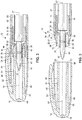
- the ferrule 18 includes a first or inner ferrule wall 24 and a second or outer ferrule wall 26 that form a well 28 therebetween.
- the inner ferrule wall 24 has a free end that extends longitudinally farther outward than a free end of the outer ferrule wall 26.
- the free end of the inner ferrule wall 24 could be recessed within the outer ferrule wall 26, or the free end of the inner ferrule wall 24 could extend to a distance even with the free end of the outer ferrule wall 26.
- a well 28 will be formed between the inner ferrule wall 24 and the outer ferrule wall 26.
- the inner ferrule wall 24 and the outer ferrule wall 26 are substantially cylindrical in shape, the inner ferrule wall 24 and the outer ferrule wall 26 being coaxial with a longitudinal axis 27 of the ferrule 18.
- the inner ferrule wall 24 and the outer ferrule wall 26 may take on other cross-sectional shapes, such as oval, square, rectangular, polygonal or virtually any other cross-sectional shape.
- the inner ferrule wall 24 and the outer ferrule wall 26 need not be coaxial.
- the inner ferrule wall 24 may be offset towards one side of the outer ferrule wall 26 such that the inner ferrule wall 24 would not share a longitudinal axis with the outer ferrule wall 26.
- the ferrule 18 includes a central bore 30 having a first portion 32 that is sized and shaped to receive at least a portion of the writing nib 20 and a second portion 34 that is sized and shaped to receive a portion of the ink reservoir 22.
- the ferrule 18 holds the writing nib 20 and the ink reservoir 22 in fluid communication with one another so that ink may be delivered from the ink reservoir 22 to the writing nib 20, for example by capillary action.
- An inner surface 36 of the first portion 32 of the central bore 30 may include an inwardly projecting annular protrusion 38 that cooperates with a corresponding annular channel 40 disposed on an outer surface 42 of the writing nib 20 to positively locate the writing nib 20 within the central bore 30 of the ferrule 18.
- the annular channel 40 can also increase the flexibility of the writing nib 20 so as to enhance the brush-like application qualities thereof.
- An outer surface of the ferrule 18 may include one or more annular protrusions 31 that cooperate with one or more inwardly projecting rings 33 on an inner surface of the barrel 12 to couple the ferrule 18 to the barrel 12.
- the annular protrusions 31 and the inwardly projecting rings 33 may take the form of threads.
- the ferrule 18 may be coupled to the barrel 12 by other means, such as epoxy, plastic welds, interference fits, or other connections.
- the cap 14 includes a first or inner cap wall 44 and a second or outer cap wall 46.
- the inner cap wall 44 may join the outer cap wall 46 at a first end 48 of the cap 14.
- the inner cap wall 44 is separated from the outer cap wall 46 by an annular space 52.
- the inner cap wall 44 and the outer cap wall 48 are substantially cylindrical in shape and the inner cap wall 44 and the outer cap wall 48 are coaxial with a longitudinal axis 54 of the cap 14.
- the inner cap wall 44 and the outer cap wall 46 may take on other cross-sectional shapes, such as oval, square, rectangular, polygonal, or virtually any other cross-sectional shape (typically, the cross-sectional shape of the cap 14 matches the cross-sectional shape of the ferrule 18).
- the inner cap wall 44 and the outer cap wall 46 need not be coaxial as long as the inner cap wall 44 is sized and shaped to at least partially fit within the well 28 in the ferrule 18.
- the inner cap wall 44 may be offset towards one side of the outer cap wall 46 such that the inner cap wall 44 would not share a longitudinal axis with the outer cap wall 46.
- the inner cap wall 44 and the outer cap wall 46 must be sized and shaped to cooperate with size and shape of the ferrule 18. More specifically, the inner cap wall 44 should be sized to fit at least partially within the well 28 of the ferrule 18 when the cap 14 is in a closed position, thereby coupling the cap 14 to the ferrule 18 and preventing undesired ink transfer from the interior of the cap 14 to the exterior of the ferrule 18 in addition to protecting the writing nib 20 from accidental damage and reducing unnecessary evaporation of ink components from the writing nib 20.
- An inner surface 80 of the inner cap wall 44 forms a central blind bore that is longitudinally aligned with the longitudinal axis 27 of the ferrule 18 when the cap 14 is coupled to the ferrule 18. The blind bore may be coaxial with the annular space 52.
- An inner surface 56 of the outer ferrule wall 26 may include an inwardly projecting protrusion 58 that cooperates with an outer surface 60 of the inner cap wall 44 to form a first seal between the ferrule 18 and the cap 14 when the cap 14 is in the closed position.
- An outer surface 62 of the outer ferrule wall 26 may include a raised annular projection 64 that cooperates with a corresponding inwardly projecting ring 66 on an inner surface 68 of the outer cap wall 46 to form a second seal between the ferrule 18 and the cap 14 when the cap 14 is in the closed position.
- the first and second seals may be reversed if desired.
- the protrusion 58 may be located on an outer surface of the inner ferrule wall and the raised annular projection 64 and the inwardly projecting rings 66 may be reversed in other embodiments.
- the inner surface 56 of the outer ferrule wall 26 may include a chamfered or angled portion 70 that cooperates with a corresponding angled surface 72 on the outer surface of the inner cap wall 44 to guide the inner cap wall 44 into the well 28 when the cap 14 is in the process of moving towards the closed position.
- the angled portion 70 may be angled relative to the longitudinal axis of the ferrule 18 by between about 2 degrees and about 40 degrees, preferably between about 5 degrees and about 25 degrees and more preferably about 15 degrees.
- the angled portion 70 forms a top opening of the well 28 that is radially larger than a bottom of the well, the angled portion 70 acting as a guiding surface that directs the inner cap wall 44 into the well when the cap 14 is in the process of being coupled to the ferrule 18.
- any ink that is transferred to the inner surface 80 of the inner cap wall 44 becomes trapped within the well 28 when the cap 14 is in the closed position, thereby preventing ink from becoming transferred to a gripping surface, such as the outer surface 62 of the outer ferrule wall 26.
- the disclosed nib assembly 16 prevents ink from adhering to a consumer's fingers when the consumer uncaps and uses the writing instrument.
- the barrel 12 may also include a receptacle (not shown) at an aft end thereof.
- the receptacle may comprise a blind bore and a receptacle wall.
- the cap 14 may be removably coupled to the aft end of the barrel 12 when the cap 14 is not in the closed position to prevent loss of the cap 14.
- the inner cap wall 44 is at least partially disposed within the receptacle and the receptacle wall may be located between the inner cap wall 44 and the outer cap wall 46 (e.g., the receptacle wall may be at least partially disposed within the annular space 52), which prevents ink from transferring from the inner surface 80 of the inner cap wall 44 to an outer surface of the barrel 12, in a manner similar to that described above for the outer surface of the ferrule 18.
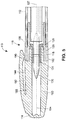
- FIG. 5 illustrates an alternative embodiment of a writing instrument 110 having a nib assembly 116 that prevents ink from being transferred from an inside surface 180 of a cap 114 to a gripping surface 162 of a ferrule 118. Only the differences between the embodiment of FIG. 5 and the embodiment of FIGS. 1-4 will be discussed while like elements will have like reference numerals, simply increased by 100.
- the cap 114 includes a single cap wall 144. That is, the cap 114 of the embodiment of FIG. 5 does not include an outer cap wall.
- the single cap wall 144 includes a distal portion 186 that is sized and shaped to be at least partially disposed within the well 128.
- the distal portion 186 is typically connected to a wider proximal portion 188 at a shoulder 190 that is sized to cooperate with the outer ferrule wall 126 to form a substantially continuous outer instrument surface 192.
- the barrel 112 may also include a receptacle (not shown) at an aft end thereof.
- the receptacle may comprise a blind bore and a receptacle wall.
- the cap 114 may be removably coupled to the aft end of the barrel 112 when the cap 114 is not in the closed position to prevent loss of the cap 114.
- the distal portion 186 of the cap wall 144 is at least partially disposed within the receptacle such that the inner surface 180 of the cap wall 144 is separated from an outer surface of the barrel 112 by the receptacle wall, which prevents ink from transferring from the inner surface 180 of the cap wall 144 to an outer surface of the barrel 112.
- the caps 14, 114 and ferrules 18, 118 described herein are preferably made from a thermoplastic material during an injection molding process.
- Suitable thermoplastic materials include polypropylene, polyethylenes, nylons, and the like.
- Other suitable materials include metals (e.g., steel, aluminum, and plated metals), glass, ceramics, and composites.
- the nib assemblies described herein may be incorporated into virtually any type of writing instrument, such as fountain pens, felt-tip pens, ball point pens, capillary action markers, and particularly brush-tip markers such as permanent ink brush tip markers, water based ink brush tip markers, and brush tip makeup or body art markers.
- the nib assemblies described herein prevent ink disposed on an inner cap surface from being transferred to an outer gripping surface where the ink could further be transferred to the fingers of a user. As a result, a consumer has a more pleasurable writing experience and a lower chance of unintentionally transferring ink from the fingers to the substrate.
Landscapes
- Pens And Brushes (AREA)
Claims (15)
- Ensemble de pointe et de capuchon pour un instrument d'écriture, comprenant :une section (18) dotée d'un premier embout et d'un deuxième embout, d'une paroi de section interne (24) et d'une paroi de section externe (26), positionnées à hauteur du premier embout, la paroi de section interne (24) et la paroi de section externe (26) étant séparées par une poche (28) comportant une ouverture à proximité du premier embout, la paroi de section interne (24) comportant un alésage central (30) ;un capuchon (14) doté d'un premier embout (48), d'un deuxième embout (50), et d'une première paroi de capuchon (44) et d'une deuxième paroi de capuchon (46), la première paroi de capuchon (44) étant dimensionnée et configurée de sorte à être au moins en partie insérée dans la poche (28) ; dans lequel la première paroi de capuchon (44) est positionnée au moins en partie dans la poche (28), entre la paroi de section interne (24) et la paroi de section externe (26), lorsque le capuchon (14) est joint à la section (18), dans lequel une pointe d'écriture (20) est positionnée au moins en partie dans l'alésage central (30) ; dans lequel la pointe d'écriture (20) est située dans l'alésage central (30) de sorte qu'une surface interne de l'alésage central est en contact avec la pointe d'écriture (20) ; dans lequel un embout libre de la première paroi de capuchon (44) est séparé d'un embout libre de la deuxième paroi de capuchon (46) par un espace annulaire (52) à hauteur du deuxième embout (50) du capuchon (14) ; etcaractérisé en ce que la première paroi de capuchon (44) s'étend dans l'alignement de la deuxième paroi de capuchon (46) dans un sens longitudinal, du premier embout (48) au deuxième embout (50).
- Ensemble de pointe et de capuchon selon la revendication 1, l'alésage central s'étendant dans la section (18), l'alésage central (30) formant une première ouverture à hauteur du premier embout de la section et une deuxième ouverture à hauteur du deuxième embout de la section, et de préférence dans lequel l'alésage central (30) inclut une première partie comportant un premier diamètre et une deuxième partie comportant un deuxième diamètre, une paroi de section interne, dans lequel le premier diamètre est inférieur au deuxième diamètre.
- Ensemble de pointe et de capuchon selon la revendication 1, dans lequel la paroi de section interne (24) et la paroi de section externe (26) incluent toutes deux un embout libre à proximité du premier embout de la section, l'embout libre de la paroi de section interne s'étendant longitudinalement vers l'extérieur plus loin que l'embout libre de la paroi de section externe.
- Ensemble de pointe et de capuchon selon la revendication 1, dans lequel l'ouverture pratiquée dans la poche (28) est formée d'une surface interne (56) de la paroi de section externe (26) et d'une surface externe de la paroi de section interne (24), la surface interne (56) de la paroi de section externe étant orientée vers l'extérieur, à distance de la paroi de section interne (24), et de préférence dans lequel l'angle de la surface interne de la paroi de section externe (26) se situe dans une plage d'environ 5 degrés à environ 25 degrés par rapport à un axe longitudinal de la section.
- Ensemble de pointe et de capuchon selon la revendication 1, dans lequel la première paroi de capuchon (44) comprend un alésage borgne central aligné sur un axe longitudinal de la section, et de préférence dans lequel un espace prévu entre une paroi de capuchon externe (46) et la première paroi de capuchon (44) comprend un espace annulaire qui est coaxial par rapport à l'alésage borne central.
- Ensemble de pointe et de capuchon selon la revendication 1, dans lequel la paroi de section interne (24) et la paroi de section externe (26) ont toutes deux généralement une configuration cylindrique, et la paroi de section interne (24) et la paroi de section externe (26) sont toutes deux sensiblement coaxiales par rapport à un axe longitudinal de la section.
- Instrument d'écriture (10) comprenant :un corps (12) comportant une ouverture à hauteur d'un premier embout et une partie centrale creuse ;un réservoir à encre (22) inséré à l'intérieur de la partie centrale creuse ;une section (18) comportant un premier embout de section et un deuxième embout de section, la section (18) étant jointe au corps à proximité de l'ouverture, la section (18) comportant une double paroi, la double paroi incluant une paroi interne (24) et une paroi externe (26), l'espace prévu entre la paroi interne (24) et la paroi externe (26) formant une poche (28) avec une ouverture à hauteur du premier embout de section, et la paroi de section interne (24) comportant un alésage central (30) ;un capuchon (14) étant doté d'un premier embout de capuchon (48), d'un deuxième embout de capuchon (50), d'une première paroi de capuchon (44), d'une deuxième paroi de capuchon (46), le capuchon (14) comportant une ouverture à hauteur du deuxième embout de capuchon (50) formé de la première paroi de capuchon (44), un embout libre de la première paroi de capuchon (44) étant situé à proximité de l'ouverture et étant dimensionné et configuré pour s'insérer dans la poche (28) entre la paroi de section interne (24) et la paroi de section externe (26) lorsque le capuchon (14) est joint à la section (18) ;dans lequel l'instrument d'écriture (10) est doté d'une pointe (20) insérée au moins en partie dans l'alésage central (30), la pointe (20) étant en communication fluidique avec le réservoir à encre (22) ; dans lequel l'embout libre de la première paroi de capuchon (44) est séparé d'un embout libre de la deuxième paroi de capuchon (46) par un espace annulaire (52) à hauteur du deuxième embout (50) du capuchon (14) ; etcaractérisé en ce que la première paroi de capuchon (44) s'étend dans l'alignement de la deuxième paroi de capuchon (46) dans un sens longitudinal, du premier embout (48) au deuxième embout (50).
- Instrument d'écriture (10) selon la revendication 7, la première paroi de capuchon (44) étant une paroi de capuchon interne et la deuxième paroi de capuchon (46) étant une paroi de capuchon externe.
- Instrument d'écriture (10) selon la revendication 7, dans lequel le réservoir à encre (22) comporte une matière fibreuse.
- Instrument d'écriture (10) selon la revendication 9, dans lequel le réservoir à encre (22) contient de l'encre dont la viscosité se situe dans la plage de 1 cps environ à 30 cps environ.
- Instrument d'écriture (10) selon la revendication 7, dans lequel le corps (12) inclut un anneau faisant saillie vers l'intérieur (33) à proximité de l'ouverture et la section (18) comprend un renfoncement correspondant ou une partie saillante dirigée vers l'extérieur qui coopère avec l'anneau faisant saillie vers l'intérieur (33) sur le corps (12) pour joindre le corps à la section.
- Instrument d'écriture (10) selon la revendication 7, dans lequel une surface interne de la paroi de section externe (26) inclut une partie saillante dirigée vers l'intérieur qui interagit avec un renfoncement correspondant ou une partie saillante dirigée vers l'extérieur sur la surface externe de la première paroi de capuchon (44) pour former un premier joint entre le capuchon (14) et la section (18) lorsque le capuchon est joint à la section.
- Instrument d'écriture (10) selon la revendication 7, dans lequel une surface externe de la paroi de section externe (26) inclut une partie saillante annulaire surélevée, et une surface interne de la première paroi de capuchon (44) inclut un renforcement correspondant ou un anneau faisant saillie vers l'intérieur qui coopère avec la partie saillante annulaire surélevée de la surface externe de la paroi de section externe (26) pour joindre le capuchon (14) à la section (18) pour former un deuxième joint entre le capuchon et la section quand le capuchon est joint à la section.
- Instrument d'écriture (10) selon la revendication 7, dans lequel la pointe d'écriture (20) est souple, et de préférence dans lequel la point d'écriture (20) comporte une pointe en plastique poreux.
- Instrument d'écriture (10) selon la revendication 7, comprenant en outre un pli annulaire situé dans l'alésage central, le pli annulaire coopérant avec un renforcement annulaire correspondant formé dans une surface externe de la pointe (20) pour joindre la pointe (20) à la section (18) dans la paroi de section interne.
Applications Claiming Priority (2)
| Application Number | Priority Date | Filing Date | Title |
|---|---|---|---|
| US13/404,964 US9248690B2 (en) | 2012-02-24 | 2012-02-24 | Nib assembly having a double wall and writing instrument comprising same |
| PCT/US2012/070954 WO2013126137A1 (fr) | 2012-02-24 | 2012-12-20 | Ensemble de pointe à double paroi et instrument d'écriture comprenant ledit ensemble |
Publications (2)
| Publication Number | Publication Date |
|---|---|
| EP2812192A1 EP2812192A1 (fr) | 2014-12-17 |
| EP2812192B1 true EP2812192B1 (fr) | 2020-02-05 |
Family
ID=47605732
Family Applications (1)
| Application Number | Title | Priority Date | Filing Date |
|---|---|---|---|
| EP12818964.4A Active EP2812192B1 (fr) | 2012-02-24 | 2012-12-20 | Ensemble de pointe à double paroi et instrument d'écriture comprenant ledit ensemble |
Country Status (5)
| Country | Link |
|---|---|
| US (1) | US9248690B2 (fr) |
| EP (1) | EP2812192B1 (fr) |
| JP (1) | JP2015511192A (fr) |
| CN (1) | CN104125886B (fr) |
| WO (1) | WO2013126137A1 (fr) |
Families Citing this family (6)
| Publication number | Priority date | Publication date | Assignee | Title |
|---|---|---|---|---|
| US9795211B2 (en) * | 2014-04-18 | 2017-10-24 | Belinda Talley | Garment dye pen |
| JP2017056002A (ja) * | 2015-09-17 | 2017-03-23 | カシオ計算機株式会社 | 描画装置及び描画方法 |
| GB2555424A (en) * | 2016-10-26 | 2018-05-02 | Guys And St Thomas Nhs Found Trust | Marker assembly for use in clinical marking |
| FR3070628B1 (fr) * | 2017-09-05 | 2020-02-14 | Societe Bic | Capuchon pour crayon |
| JP2019177611A (ja) * | 2018-03-30 | 2019-10-17 | シヤチハタ株式会社 | 筆記具 |
| EP4037915A4 (fr) * | 2019-09-30 | 2023-11-29 | Sanford, L.P. | Ensembles pointe d'écriture et instruments d'écriture |
Citations (2)
| Publication number | Priority date | Publication date | Assignee | Title |
|---|---|---|---|---|
| GB2262261A (en) * | 1991-12-10 | 1993-06-16 | Sakura Color Prod Corp | Anti-drying arrangement for a writing instrument nib. |
| JPH0634987U (ja) * | 1992-10-15 | 1994-05-10 | 株式会社壽 | ペンのキャップ構造 |
Family Cites Families (14)
| Publication number | Priority date | Publication date | Assignee | Title |
|---|---|---|---|---|
| US2140559A (en) * | 1936-10-07 | 1938-12-20 | Scully Signal Co | Audible signal device |
| US2498166A (en) * | 1946-09-21 | 1950-02-21 | Kuriyama Fred Yoshiharu | Fountain pen |
| US3221360A (en) * | 1963-03-11 | 1965-12-07 | Blaisdell Pencil Company | Marking device construction |
| FR2435358A1 (fr) * | 1978-09-11 | 1980-04-04 | Dupont S T | Instrument a ecrire |
| DE8401449U1 (de) | 1984-01-19 | 1985-07-18 | Pelikan Ag, 3000 Hannover | Schreibgerät mit einer abnehmbaren Kappe |
| FR2600976B1 (fr) | 1986-07-07 | 1988-09-30 | Oreal | Recipient comprenant un col et une capsule manoeuvrable avec une seule main |
| JPH0742793Y2 (ja) * | 1989-08-31 | 1995-10-04 | ぺんてる株式会社 | 筆記具のキャップ装着構造 |
| JPH05305794A (ja) | 1992-03-02 | 1993-11-19 | Sakura Color Prod Corp | 塗布具及びそのキャップ |
| JP2892973B2 (ja) * | 1995-06-22 | 1999-05-17 | 株式会社パイロット | 筆記具又は塗布具用キャップ |
| JP3796287B2 (ja) * | 1996-02-15 | 2006-07-12 | ゼブラ株式会社 | 筆記具 |
| JP4368986B2 (ja) * | 1999-10-06 | 2009-11-18 | パイロットインキ株式会社 | 筆記具 |
| JP2004025763A (ja) * | 2002-06-28 | 2004-01-29 | Pentel Corp | 塗布具 |
| JP4585777B2 (ja) * | 2003-07-07 | 2010-11-24 | パイロットインキ株式会社 | 筆記具 |
| DE102005032548A1 (de) * | 2005-07-12 | 2007-01-18 | Montblanc-Simplo Gmbh | Schreibgerät |
-
2012
- 2012-02-24 US US13/404,964 patent/US9248690B2/en active Active
- 2012-12-20 JP JP2014558734A patent/JP2015511192A/ja active Pending
- 2012-12-20 EP EP12818964.4A patent/EP2812192B1/fr active Active
- 2012-12-20 CN CN201280070146.2A patent/CN104125886B/zh active Active
- 2012-12-20 WO PCT/US2012/070954 patent/WO2013126137A1/fr not_active Ceased
Patent Citations (2)
| Publication number | Priority date | Publication date | Assignee | Title |
|---|---|---|---|---|
| GB2262261A (en) * | 1991-12-10 | 1993-06-16 | Sakura Color Prod Corp | Anti-drying arrangement for a writing instrument nib. |
| JPH0634987U (ja) * | 1992-10-15 | 1994-05-10 | 株式会社壽 | ペンのキャップ構造 |
Also Published As
| Publication number | Publication date |
|---|---|
| CN104125886B (zh) | 2016-10-05 |
| JP2015511192A (ja) | 2015-04-16 |
| US9248690B2 (en) | 2016-02-02 |
| WO2013126137A1 (fr) | 2013-08-29 |
| US20130223916A1 (en) | 2013-08-29 |
| EP2812192A1 (fr) | 2014-12-17 |
| CN104125886A (zh) | 2014-10-29 |
Similar Documents
| Publication | Publication Date | Title |
|---|---|---|
| US9248690B2 (en) | Nib assembly having a double wall and writing instrument comprising same | |
| CN101631682B (zh) | 用于可缩进器具的密封组件 | |
| CN109863039B (zh) | 书写工具 | |
| US7563046B2 (en) | Fluid dispensers having removably attached dual applicator assembly | |
| US9636940B2 (en) | Writing instrument | |
| CN101500821B (zh) | 具有防止干燥装置的滑动式书写工具 | |
| US11148462B2 (en) | Retractable nosecone writing instrument | |
| US8944716B2 (en) | Valved applicator | |
| JP6145272B2 (ja) | 塗布具 | |
| US20050042015A1 (en) | Bold-fine multiple width marking instrument | |
| JP2018122566A (ja) | 筆記具 | |
| US10493790B2 (en) | Multiple color marker | |
| RU2350475C2 (ru) | Комбинированный пишущий инструмент | |
| US7806616B2 (en) | Writing instrument barrel including a painted inner surface | |
| JP2009160939A (ja) | 出没式筆記具 | |
| CN105538956B (zh) | 一种揿动笔 | |
| EP2920003B1 (fr) | Ensemble de libération de bouchon de remplissage et instrument d'écriture le comportant | |
| US12162305B2 (en) | Knock-type writing instrument | |
| WO2020222141A1 (fr) | Élément rétractable pour instrument d'écriture | |
| JP3629685B2 (ja) | キャップ式エアタイト筆記具 | |
| US12179510B2 (en) | Friction body unit and thermochromic writing instrument | |
| US20070110499A1 (en) | Dual-purpose pen for painting | |
| JP3172744U (ja) | 多芯筆記具及びそれに用いる筆記体 | |
| JP2008087422A (ja) | 筆記具 | |
| JP2014108600A (ja) | 筆記具 |
Legal Events
| Date | Code | Title | Description |
|---|---|---|---|
| PUAI | Public reference made under article 153(3) epc to a published international application that has entered the european phase |
Free format text: ORIGINAL CODE: 0009012 |
|
| 17P | Request for examination filed |
Effective date: 20140912 |
|
| AK | Designated contracting states |
Kind code of ref document: A1 Designated state(s): AL AT BE BG CH CY CZ DE DK EE ES FI FR GB GR HR HU IE IS IT LI LT LU LV MC MK MT NL NO PL PT RO RS SE SI SK SM TR |
|
| AX | Request for extension of the european patent |
Extension state: BA ME |
|
| DAX | Request for extension of the european patent (deleted) | ||
| STAA | Information on the status of an ep patent application or granted ep patent |
Free format text: STATUS: EXAMINATION IS IN PROGRESS |
|
| 17Q | First examination report despatched |
Effective date: 20170913 |
|
| GRAP | Despatch of communication of intention to grant a patent |
Free format text: ORIGINAL CODE: EPIDOSNIGR1 |
|
| STAA | Information on the status of an ep patent application or granted ep patent |
Free format text: STATUS: GRANT OF PATENT IS INTENDED |
|
| INTG | Intention to grant announced |
Effective date: 20190805 |
|
| GRAS | Grant fee paid |
Free format text: ORIGINAL CODE: EPIDOSNIGR3 |
|
| GRAA | (expected) grant |
Free format text: ORIGINAL CODE: 0009210 |
|
| STAA | Information on the status of an ep patent application or granted ep patent |
Free format text: STATUS: THE PATENT HAS BEEN GRANTED |
|
| AK | Designated contracting states |
Kind code of ref document: B1 Designated state(s): AL AT BE BG CH CY CZ DE DK EE ES FI FR GB GR HR HU IE IS IT LI LT LU LV MC MK MT NL NO PL PT RO RS SE SI SK SM TR |
|
| REG | Reference to a national code |
Ref country code: GB Ref legal event code: FG4D |
|
| REG | Reference to a national code |
Ref country code: AT Ref legal event code: REF Ref document number: 1229639 Country of ref document: AT Kind code of ref document: T Effective date: 20200215 |
|
| REG | Reference to a national code |
Ref country code: DE Ref legal event code: R096 Ref document number: 602012067593 Country of ref document: DE |
|
| REG | Reference to a national code |
Ref country code: IE Ref legal event code: FG4D |
|
| REG | Reference to a national code |
Ref country code: CH Ref legal event code: EP |
|
| REG | Reference to a national code |
Ref country code: NL Ref legal event code: MP Effective date: 20200205 |
|
| PG25 | Lapsed in a contracting state [announced via postgrant information from national office to epo] |
Ref country code: RS Free format text: LAPSE BECAUSE OF FAILURE TO SUBMIT A TRANSLATION OF THE DESCRIPTION OR TO PAY THE FEE WITHIN THE PRESCRIBED TIME-LIMIT Effective date: 20200205 Ref country code: FI Free format text: LAPSE BECAUSE OF FAILURE TO SUBMIT A TRANSLATION OF THE DESCRIPTION OR TO PAY THE FEE WITHIN THE PRESCRIBED TIME-LIMIT Effective date: 20200205 Ref country code: NO Free format text: LAPSE BECAUSE OF FAILURE TO SUBMIT A TRANSLATION OF THE DESCRIPTION OR TO PAY THE FEE WITHIN THE PRESCRIBED TIME-LIMIT Effective date: 20200505 Ref country code: PT Free format text: LAPSE BECAUSE OF FAILURE TO SUBMIT A TRANSLATION OF THE DESCRIPTION OR TO PAY THE FEE WITHIN THE PRESCRIBED TIME-LIMIT Effective date: 20200628 |
|
| REG | Reference to a national code |
Ref country code: LT Ref legal event code: MG4D |
|
| PG25 | Lapsed in a contracting state [announced via postgrant information from national office to epo] |
Ref country code: BG Free format text: LAPSE BECAUSE OF FAILURE TO SUBMIT A TRANSLATION OF THE DESCRIPTION OR TO PAY THE FEE WITHIN THE PRESCRIBED TIME-LIMIT Effective date: 20200505 Ref country code: LV Free format text: LAPSE BECAUSE OF FAILURE TO SUBMIT A TRANSLATION OF THE DESCRIPTION OR TO PAY THE FEE WITHIN THE PRESCRIBED TIME-LIMIT Effective date: 20200205 Ref country code: SE Free format text: LAPSE BECAUSE OF FAILURE TO SUBMIT A TRANSLATION OF THE DESCRIPTION OR TO PAY THE FEE WITHIN THE PRESCRIBED TIME-LIMIT Effective date: 20200205 Ref country code: HR Free format text: LAPSE BECAUSE OF FAILURE TO SUBMIT A TRANSLATION OF THE DESCRIPTION OR TO PAY THE FEE WITHIN THE PRESCRIBED TIME-LIMIT Effective date: 20200205 Ref country code: GR Free format text: LAPSE BECAUSE OF FAILURE TO SUBMIT A TRANSLATION OF THE DESCRIPTION OR TO PAY THE FEE WITHIN THE PRESCRIBED TIME-LIMIT Effective date: 20200506 Ref country code: IS Free format text: LAPSE BECAUSE OF FAILURE TO SUBMIT A TRANSLATION OF THE DESCRIPTION OR TO PAY THE FEE WITHIN THE PRESCRIBED TIME-LIMIT Effective date: 20200605 |
|
| PG25 | Lapsed in a contracting state [announced via postgrant information from national office to epo] |
Ref country code: NL Free format text: LAPSE BECAUSE OF FAILURE TO SUBMIT A TRANSLATION OF THE DESCRIPTION OR TO PAY THE FEE WITHIN THE PRESCRIBED TIME-LIMIT Effective date: 20200205 |
|
| PG25 | Lapsed in a contracting state [announced via postgrant information from national office to epo] |
Ref country code: SK Free format text: LAPSE BECAUSE OF FAILURE TO SUBMIT A TRANSLATION OF THE DESCRIPTION OR TO PAY THE FEE WITHIN THE PRESCRIBED TIME-LIMIT Effective date: 20200205 Ref country code: CZ Free format text: LAPSE BECAUSE OF FAILURE TO SUBMIT A TRANSLATION OF THE DESCRIPTION OR TO PAY THE FEE WITHIN THE PRESCRIBED TIME-LIMIT Effective date: 20200205 Ref country code: RO Free format text: LAPSE BECAUSE OF FAILURE TO SUBMIT A TRANSLATION OF THE DESCRIPTION OR TO PAY THE FEE WITHIN THE PRESCRIBED TIME-LIMIT Effective date: 20200205 Ref country code: SM Free format text: LAPSE BECAUSE OF FAILURE TO SUBMIT A TRANSLATION OF THE DESCRIPTION OR TO PAY THE FEE WITHIN THE PRESCRIBED TIME-LIMIT Effective date: 20200205 Ref country code: EE Free format text: LAPSE BECAUSE OF FAILURE TO SUBMIT A TRANSLATION OF THE DESCRIPTION OR TO PAY THE FEE WITHIN THE PRESCRIBED TIME-LIMIT Effective date: 20200205 Ref country code: DK Free format text: LAPSE BECAUSE OF FAILURE TO SUBMIT A TRANSLATION OF THE DESCRIPTION OR TO PAY THE FEE WITHIN THE PRESCRIBED TIME-LIMIT Effective date: 20200205 Ref country code: LT Free format text: LAPSE BECAUSE OF FAILURE TO SUBMIT A TRANSLATION OF THE DESCRIPTION OR TO PAY THE FEE WITHIN THE PRESCRIBED TIME-LIMIT Effective date: 20200205 Ref country code: ES Free format text: LAPSE BECAUSE OF FAILURE TO SUBMIT A TRANSLATION OF THE DESCRIPTION OR TO PAY THE FEE WITHIN THE PRESCRIBED TIME-LIMIT Effective date: 20200205 |
|
| REG | Reference to a national code |
Ref country code: DE Ref legal event code: R097 Ref document number: 602012067593 Country of ref document: DE |
|
| REG | Reference to a national code |
Ref country code: AT Ref legal event code: MK05 Ref document number: 1229639 Country of ref document: AT Kind code of ref document: T Effective date: 20200205 |
|
| PLBE | No opposition filed within time limit |
Free format text: ORIGINAL CODE: 0009261 |
|
| STAA | Information on the status of an ep patent application or granted ep patent |
Free format text: STATUS: NO OPPOSITION FILED WITHIN TIME LIMIT |
|
| 26N | No opposition filed |
Effective date: 20201106 |
|
| PG25 | Lapsed in a contracting state [announced via postgrant information from national office to epo] |
Ref country code: AT Free format text: LAPSE BECAUSE OF FAILURE TO SUBMIT A TRANSLATION OF THE DESCRIPTION OR TO PAY THE FEE WITHIN THE PRESCRIBED TIME-LIMIT Effective date: 20200205 Ref country code: IT Free format text: LAPSE BECAUSE OF FAILURE TO SUBMIT A TRANSLATION OF THE DESCRIPTION OR TO PAY THE FEE WITHIN THE PRESCRIBED TIME-LIMIT Effective date: 20200205 |
|
| PG25 | Lapsed in a contracting state [announced via postgrant information from national office to epo] |
Ref country code: SI Free format text: LAPSE BECAUSE OF FAILURE TO SUBMIT A TRANSLATION OF THE DESCRIPTION OR TO PAY THE FEE WITHIN THE PRESCRIBED TIME-LIMIT Effective date: 20200205 Ref country code: PL Free format text: LAPSE BECAUSE OF FAILURE TO SUBMIT A TRANSLATION OF THE DESCRIPTION OR TO PAY THE FEE WITHIN THE PRESCRIBED TIME-LIMIT Effective date: 20200205 |
|
| REG | Reference to a national code |
Ref country code: CH Ref legal event code: PL |
|
| PG25 | Lapsed in a contracting state [announced via postgrant information from national office to epo] |
Ref country code: MC Free format text: LAPSE BECAUSE OF FAILURE TO SUBMIT A TRANSLATION OF THE DESCRIPTION OR TO PAY THE FEE WITHIN THE PRESCRIBED TIME-LIMIT Effective date: 20200205 |
|
| REG | Reference to a national code |
Ref country code: BE Ref legal event code: MM Effective date: 20201231 |
|
| PG25 | Lapsed in a contracting state [announced via postgrant information from national office to epo] |
Ref country code: IE Free format text: LAPSE BECAUSE OF NON-PAYMENT OF DUE FEES Effective date: 20201220 Ref country code: LU Free format text: LAPSE BECAUSE OF NON-PAYMENT OF DUE FEES Effective date: 20201220 |
|
| PG25 | Lapsed in a contracting state [announced via postgrant information from national office to epo] |
Ref country code: LI Free format text: LAPSE BECAUSE OF NON-PAYMENT OF DUE FEES Effective date: 20201231 Ref country code: CH Free format text: LAPSE BECAUSE OF NON-PAYMENT OF DUE FEES Effective date: 20201231 |
|
| PG25 | Lapsed in a contracting state [announced via postgrant information from national office to epo] |
Ref country code: TR Free format text: LAPSE BECAUSE OF FAILURE TO SUBMIT A TRANSLATION OF THE DESCRIPTION OR TO PAY THE FEE WITHIN THE PRESCRIBED TIME-LIMIT Effective date: 20200205 Ref country code: MT Free format text: LAPSE BECAUSE OF FAILURE TO SUBMIT A TRANSLATION OF THE DESCRIPTION OR TO PAY THE FEE WITHIN THE PRESCRIBED TIME-LIMIT Effective date: 20200205 Ref country code: CY Free format text: LAPSE BECAUSE OF FAILURE TO SUBMIT A TRANSLATION OF THE DESCRIPTION OR TO PAY THE FEE WITHIN THE PRESCRIBED TIME-LIMIT Effective date: 20200205 |
|
| PG25 | Lapsed in a contracting state [announced via postgrant information from national office to epo] |
Ref country code: MK Free format text: LAPSE BECAUSE OF FAILURE TO SUBMIT A TRANSLATION OF THE DESCRIPTION OR TO PAY THE FEE WITHIN THE PRESCRIBED TIME-LIMIT Effective date: 20200205 Ref country code: AL Free format text: LAPSE BECAUSE OF FAILURE TO SUBMIT A TRANSLATION OF THE DESCRIPTION OR TO PAY THE FEE WITHIN THE PRESCRIBED TIME-LIMIT Effective date: 20200205 |
|
| PG25 | Lapsed in a contracting state [announced via postgrant information from national office to epo] |
Ref country code: BE Free format text: LAPSE BECAUSE OF NON-PAYMENT OF DUE FEES Effective date: 20201231 |
|
| REG | Reference to a national code |
Ref country code: DE Ref legal event code: R082 Ref document number: 602012067593 Country of ref document: DE Representative=s name: WESTPHAL, MUSSGNUG & PARTNER PATENTANWAELTE MI, DE |
|
| PGFP | Annual fee paid to national office [announced via postgrant information from national office to epo] |
Ref country code: GB Payment date: 20251229 Year of fee payment: 14 |
|
| PGFP | Annual fee paid to national office [announced via postgrant information from national office to epo] |
Ref country code: FR Payment date: 20251226 Year of fee payment: 14 |
|
| PGFP | Annual fee paid to national office [announced via postgrant information from national office to epo] |
Ref country code: DE Payment date: 20251229 Year of fee payment: 14 |