EP2813652A1 - Entriegelungsvorrichtung für kraftfahrzeugtürschloss - Google Patents
Entriegelungsvorrichtung für kraftfahrzeugtürschloss Download PDFInfo
- Publication number
- EP2813652A1 EP2813652A1 EP13747048.0A EP13747048A EP2813652A1 EP 2813652 A1 EP2813652 A1 EP 2813652A1 EP 13747048 A EP13747048 A EP 13747048A EP 2813652 A1 EP2813652 A1 EP 2813652A1
- Authority
- EP
- European Patent Office
- Prior art keywords
- latch release
- operating member
- emergency
- latch
- state
- Prior art date
- Legal status (The legal status is an assumption and is not a legal conclusion. Google has not performed a legal analysis and makes no representation as to the accuracy of the status listed.)
- Granted
Links
Images



Classifications
-
- E—FIXED CONSTRUCTIONS
- E05—LOCKS; KEYS; WINDOW OR DOOR FITTINGS; SAFES
- E05B—LOCKS; ACCESSORIES THEREFOR; HANDCUFFS
- E05B81/00—Power-actuated vehicle locks
-
- E—FIXED CONSTRUCTIONS
- E05—LOCKS; KEYS; WINDOW OR DOOR FITTINGS; SAFES
- E05B—LOCKS; ACCESSORIES THEREFOR; HANDCUFFS
- E05B81/00—Power-actuated vehicle locks
- E05B81/54—Electrical circuits
- E05B81/90—Manual override in case of power failure
-
- E—FIXED CONSTRUCTIONS
- E05—LOCKS; KEYS; WINDOW OR DOOR FITTINGS; SAFES
- E05B—LOCKS; ACCESSORIES THEREFOR; HANDCUFFS
- E05B85/00—Details of vehicle locks not provided for in groups E05B77/00 - E05B83/00
- E05B85/10—Handles
- E05B85/12—Inner door handles
-
- E—FIXED CONSTRUCTIONS
- E05—LOCKS; KEYS; WINDOW OR DOOR FITTINGS; SAFES
- E05B—LOCKS; ACCESSORIES THEREFOR; HANDCUFFS
- E05B63/00—Locks or fastenings with special structural characteristics
- E05B63/0065—Operating modes; Transformable to different operating modes
-
- E—FIXED CONSTRUCTIONS
- E05—LOCKS; KEYS; WINDOW OR DOOR FITTINGS; SAFES
- E05B—LOCKS; ACCESSORIES THEREFOR; HANDCUFFS
- E05B79/00—Mounting or connecting vehicle locks or parts thereof
- E05B79/10—Connections between movable lock parts
- E05B79/20—Connections between movable lock parts using flexible connections, e.g. Bowden cables
-
- Y—GENERAL TAGGING OF NEW TECHNOLOGICAL DEVELOPMENTS; GENERAL TAGGING OF CROSS-SECTIONAL TECHNOLOGIES SPANNING OVER SEVERAL SECTIONS OF THE IPC; TECHNICAL SUBJECTS COVERED BY FORMER USPC CROSS-REFERENCE ART COLLECTIONS [XRACs] AND DIGESTS
- Y10—TECHNICAL SUBJECTS COVERED BY FORMER USPC
- Y10T—TECHNICAL SUBJECTS COVERED BY FORMER US CLASSIFICATION
- Y10T292/00—Closure fasteners
- Y10T292/57—Operators with knobs or handles
Definitions
- the present invention relates to a vehicle door latch release device that includes an operating member for latch release that is operated by a vehicle user in order to release a latched state of a door, an electric actuator that is operated in response to the operating member for latch release being operated, and a latch device that is provided on the door so as to enable latch release in response to operation of the electric actuator and mechanical input of a latch release operating force, input of a mechanical latch release operating force into the latch device being enabled in an emergency in which latch release by the electric actuator is disabled.
- Patent Document 1 Japanese Utility Model Publication No. 6-35091
- the present invention has been accomplished in light of such circumstances, and it is an object thereof to provide a vehicle door latch release device that can prevent an emergency operation from being mistakenly carried out when it is unnecessary to input a mechanical latch release operating force into a latch device.
- the operating member for latch release and the restriction/permission switching means are operatively linked so that the restriction/permission switching means is switched from the operation restricted state to the operation permitted state in response to operation of the operating member for latch release by a vehicle user in a mode different from operation of the operating member for latch release in order to operate the electric actuator.
- An electric motor for latch release 14 of an embodiment corresponds to the electric actuator of the present invention
- a push button 35 of the embodiment corresponds to the operating member for latch release of the present invention
- a front side door D of the embodiment corresponds to the door the present invention.
- the emergency operating member for inputting a mechanical latch release operating force into the latch device via the operating force transmission means becomes operable in response to the restriction/permission switching means attaining the operation permitted state in response to a predetermined operation by a vehicle user; since it is necessary for the vehicle user to carry out the predetermined operation in order to operate the emergency operating member, it is possible to avoid the emergency operating member from being operated unnecessarily.
- FIG. 1 a door of a passenger vehicle, for example, a front side door D, has mounted thereon a handle 11 for a vehicle user to carry out an open/close operation of the front side door D on the vehicle compartment side and has disposed thereon a latch device 12 that enables switching between a latched state in which a closed state of the front side door D is maintained by engaging with the vehicle body side and an unlatched state in which the front side door D can be opened.
- This latch device 12 includes a reversible electric motor for an lock/unlock switch 13 that exhibits power for switching between an unlocked state in which latch release of the front side door D is enabled and a locked state in which latch release of the front side door D is disabled, and an electric motor for latch release 14, which is an electric actuator that exhibits power for releasing the latched state in the unlocked state.
- the latch device 12 can carry out latch release in response to a mechanical input of a latch release operating force either in the locked state or the unlocked state.
- the handle main body 15 is formed from a grip portion 15a extending lengthwise in the fore-and-aft direction of the vehicle, a circular front support portion 15b provided so as to be connected to the front end of the grip portion 15a, and a rear support portion 15c formed into a circular shape that is larger than the front support portion 15b and provided so as to be connected to the rear end of the grip portion 15a.
- the front support portion 15b and the rear support portion 15c of the handle main body 15, which is inclined upwardly toward the front, are fixed to the inner face side of the front side door D.
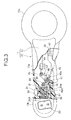
- a switch for lock/unlock switching 20 Disposed on a face, opposing the interior of the vehicle compartment, of the front support portion 15b of the handle main body 15 as clearly shown in FIG. 3 is a switch for lock/unlock switching 20, which operates the electric motor for lock/unlock switching 13 of the latch device 12 by switching between forward and reverse directions of rotation.
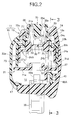
- This switch case 23 integrally has a first cylindrical portion 23a that is inserted into the plurality of support leg portions 21b of the bracket 21 and has a lower end part abutting against the support plate portion 21 a of the bracket 21 from above, and a first inward collar portion 23b that protrudes radially inwardly from the upper end of the first cylindrical portion 23 a.
- an engagement claw portion 23c Projectingly provided integrally with a plurality of locations in the peripheral direction of the lower end of the first cylindrical portion 23a is an engagement claw portion 23c that is inserted through a through hole 51 provided in the support plate portion 21a and resiliently engages with the support plate portion 21a from below, and projectingly provided integrally with an outer face of a plurality of locations in the peripheral direction of the first cylindrical portion 23a is an engagement projecting portion 23d that resiliently engages with a support leg portion 21b selected from the plurality of support leg portions 21b of the bracket 21.
- a downwardly facing annular first step part 28 Formed between said other end of the board mounting hole 25 and said one end of the small diameter hole 26 is a downwardly facing annular first step part 28, and between said other end of the small diameter hole 26 and said one end of the large diameter hole 27 is an upwardly facing annular second step part 29.
- a rectangular board 30 Inserted into the board mounting hole 25 is a rectangular board 30 having an edge on the outer periphery abutting against the first step part 28, and fixed onto the board 30 is a tact switch 31 that has a to-be-pressed portion 31 a in the center of an end part on the side opposite to the board 30 and changes switching mode in response to application of a pressing force to the to-be-pressed portion 31a. Furthermore, a cylindrical projecting portion 21c forming an outlet hole 32 is provided integrally with a central part of the support plate portion 21a of the bracket 21 so as to protrude upwardly, and a wire (not illustrated) extending from the board 30 is guided outside the switch case 23 via the outlet hole 32.
- a circular button insertion hole 34 is provided in a front upper face of the grip portion 15a of the handle 11 so as to correspond to the switch case 23 and the switch holder 24A, and a push button 35 is disposed in the button insertion hole 34, the push button 35 being an operating member for latch release.
- the push button 35 integrally has a button main portion 35a formed into a stepped bottomed cylindrical shape having an upper end closed and having a third step portion 35c on the outer periphery of an intermediate part, a collar portion 35b protruding radially outwardly from the lower end of the button main portion 35a, and a rod-shaped pressing portion 35d extending downwardly from an inner face of a central part at the blocked end of the button main portion 35a.
- a first return spring 36 which is a coil spring, is provided in a compressed state between the second step part 29 of the switch holder 24A and the blocked part at the upper end of the push button 35, and in a natural state in which no external force is applied, the end of upward movement of the push button 35 urged upward by the first return spring 36 is restricted by the collar portion 35b of the push button 35 abutting against the first inward collar portion 23b at the upper end of the switch case 23 from below, in this process the blocked part at the upper end of the push button 35 being positioned so as to project upwardly slightly from a front part of the grip portion 15a of the handle 11.
- a second return spring 37 which is a coil spring, is provided in a compressed state between the second inward collar portion 24b of the switch holder 24A and the support plate portion 21a of the bracket 21, and the spring force of the second return spring 37 is set so as to be larger than the spring force of the first return spring 36. Therefore, in a state in which the push button 35 has been pushed in against the spring force of the first return spring 36 and change in the relative position in the vertical direction between the push button 35 and the switch holder 24A is restricted, when the push button 35 is pushed in against the spring force of the second return spring 37 with a larger force the push button 35 and the switch holder 24A move downwardly within the switch case 23.
- the emergency operating member 39 which can be operated by a vehicle user, is pivotably supported on the grip portion 15a of the handle main body 15 of the handle 11, and a human force due to the emergency operating member 39 being operated by the vehicle user is transmitted as a mechanical latch release operating force to the latch device 12 via the operating force transmission means 42. Since the restriction/permission switching means 48A switches between the operation restricted state, in which operation of the emergency operating member 39 is restricted, and the operation permitted state, in which operation of the emergency operating member 39 is enabled in response to the predetermined operation by the vehicle user, it is necessary for the vehicle user to carry out the predetermined operation in order to operate the emergency operating member 39, and it is possible to avoid the emergency operating member 39 from being operated unnecessarily.
- a second embodiment of the present invention is explained by reference to FIG. 6 . Parts corresponding to those of the first embodiment are only denoted and illustrated by the same reference numerals and symbols, and a detailed explanation thereof is omitted.
- Restriction/permission switching means 48B switches between an operation restricted state in which operation of an emergency operating member 39 is restricted and an operation permitted state in which operation of the emergency operating member 39 is enabled in response to a predetermined operation by a vehicle user, this restriction/permission switching means 48B including a slide member 49' supported in a lower part within a grip portion 15a of a handle main body 15 so that it can slide in the fore-and-aft direction and disposed in front of the emergency operating member 39, and a spring 50 provided between the grip portion 15a and the slide member 49' so as to exhibit a spring force urging the slide member 49' toward the emergency operating member 39.
Landscapes
- Lock And Its Accessories (AREA)
Applications Claiming Priority (2)
| Application Number | Priority Date | Filing Date | Title |
|---|---|---|---|
| JP2012026213A JP5734219B2 (ja) | 2012-02-09 | 2012-02-09 | 車両用ドアのラッチ解除装置 |
| PCT/JP2013/050220 WO2013118526A1 (ja) | 2012-02-09 | 2013-01-09 | 車両用ドアのラッチ解除装置 |
Publications (3)
| Publication Number | Publication Date |
|---|---|
| EP2813652A1 true EP2813652A1 (de) | 2014-12-17 |
| EP2813652A4 EP2813652A4 (de) | 2016-03-09 |
| EP2813652B1 EP2813652B1 (de) | 2020-12-02 |
Family
ID=48947295
Family Applications (1)
| Application Number | Title | Priority Date | Filing Date |
|---|---|---|---|
| EP13747048.0A Not-in-force EP2813652B1 (de) | 2012-02-09 | 2013-01-09 | Entriegelungsvorrichtung für kraftfahrzeugtürschloss |
Country Status (5)
| Country | Link |
|---|---|
| US (1) | US9580939B2 (de) |
| EP (1) | EP2813652B1 (de) |
| JP (1) | JP5734219B2 (de) |
| CN (1) | CN104114794B (de) |
| WO (1) | WO2013118526A1 (de) |
Cited By (1)
| Publication number | Priority date | Publication date | Assignee | Title |
|---|---|---|---|---|
| EP2871310B1 (de) * | 2012-07-09 | 2019-11-13 | Kabushiki Kaisha Honda Lock | Verriegelungslösungsvorrichtung für eine fahrzeugtür |
Families Citing this family (11)
| Publication number | Priority date | Publication date | Assignee | Title |
|---|---|---|---|---|
| DE102014114512A1 (de) * | 2014-10-07 | 2016-04-07 | Kiekert Aktiengesellschaft | Kraftfahrzeugtürverschluss |
| WO2017109852A1 (ja) | 2015-12-22 | 2017-06-29 | 三井金属アクト株式会社 | 自動車用ドアロック装置 |
| JP6588832B2 (ja) * | 2016-01-14 | 2019-10-09 | 東京パーツ工業株式会社 | ドアハンドル装置 |
| US9988830B2 (en) * | 2016-03-03 | 2018-06-05 | Dan Raz Ltd. | Latch arrangement having a handle |
| JP7106669B2 (ja) | 2018-10-01 | 2022-07-26 | 三井化学株式会社 | 積層体および積層体の製造方法 |
| JP6975698B2 (ja) * | 2018-10-16 | 2021-12-01 | 本田技研工業株式会社 | 車両のスライドドア装置 |
| DE102019125947B4 (de) * | 2019-09-26 | 2021-05-12 | Lisa Dräxlmaier GmbH | Notbetätigungsvorrichtung zum manuellen öffnen einer fahrzeugtür |
| CN111270925B (zh) * | 2019-12-25 | 2021-07-27 | 浙江零跑科技有限公司 | 双驱动式拉线结构及利用该结构的内外双向双驱动式门锁 |
| US11668120B2 (en) | 2020-07-27 | 2023-06-06 | Rivian Ip Holdings, Llc | Automatic door release with mechanical linkage |
| KR102461728B1 (ko) * | 2021-06-17 | 2022-11-01 | 유한회사 아이티더블유오토모티브코리아 | 자동차 도어용 인사이드 핸들 |
| CN117747331B (zh) * | 2023-10-20 | 2024-11-29 | 深圳引望智能技术有限公司 | 按压开关、车门和汽车 |
Family Cites Families (19)
| Publication number | Priority date | Publication date | Assignee | Title |
|---|---|---|---|---|
| JPS6418268U (de) * | 1987-07-20 | 1989-01-30 | ||
| JPH0635091Y2 (ja) * | 1988-03-23 | 1994-09-14 | 愛三工業株式会社 | 車輌用ドアの閉状態解除装置 |
| JP2562847Y2 (ja) | 1992-10-14 | 1998-02-16 | 株式会社ホンダアクセス | 自動2輪車用車体カバー装置 |
| US5642636A (en) * | 1993-01-22 | 1997-07-01 | Mitsui Kinzoku Kogyo Kabushiki Kaisha | Locking device for trunk lids |
| US6048002A (en) * | 1998-02-20 | 2000-04-11 | Asmo Co., Ltd. | Door locking-unlocking system for vehicle |
| KR100380454B1 (ko) * | 2000-11-30 | 2003-04-26 | 현대자동차주식회사 | 자동차의 트렁크 비상탈출용 오픈장치 |
| US6896302B2 (en) * | 2001-08-17 | 2005-05-24 | Illinois Tool Works Inc. | Push button release apparatus |
| JP3906341B2 (ja) * | 2001-09-18 | 2007-04-18 | 三井金属鉱業株式会社 | 車両用ゲートロック装置 |
| JP2003097124A (ja) * | 2001-09-27 | 2003-04-03 | Nabco Ltd | 車両用ドアのロック装置 |
| KR100501395B1 (ko) * | 2003-10-14 | 2005-07-18 | 기아자동차주식회사 | 차량의 트렁크리드 래치어셈블리 |
| JP4321404B2 (ja) * | 2004-08-19 | 2009-08-26 | アイシン精機株式会社 | 車両用ドアロック装置 |
| JP4296148B2 (ja) * | 2004-12-01 | 2009-07-15 | 三井金属鉱業株式会社 | ドアラッチ装置 |
| DE102004058874A1 (de) * | 2004-12-06 | 2006-06-08 | Huf Hülsbeck & Fürst Gmbh & Co. Kg | Türaußengriff für ein Kraftfahrzeug |
| JP4598668B2 (ja) * | 2005-12-19 | 2010-12-15 | 株式会社アルファ | 車両用ドアロック装置 |
| WO2008039935A2 (en) * | 2006-09-27 | 2008-04-03 | Strattec Power Access Llc | Uni-directional cinching latch assembly and method of operating a cinching latch assembly |
| JP2009228306A (ja) * | 2008-03-24 | 2009-10-08 | Aisin Kiko Co Ltd | 電動式ドアラッチ装置 |
| JP4914478B2 (ja) | 2009-11-02 | 2012-04-11 | 本田技研工業株式会社 | ドアハンドルストローク切替構造 |
| US20110112689A1 (en) | 2009-11-06 | 2011-05-12 | Gm Global Technology Operations, Inc. | Egress latch |
| JP5292366B2 (ja) * | 2010-08-02 | 2013-09-18 | 株式会社ホンダロック | 車両用ドアロック装置 |
-
2012
- 2012-02-09 JP JP2012026213A patent/JP5734219B2/ja active Active
-
2013
- 2013-01-09 EP EP13747048.0A patent/EP2813652B1/de not_active Not-in-force
- 2013-01-09 US US14/376,469 patent/US9580939B2/en not_active Expired - Fee Related
- 2013-01-09 CN CN201380008728.2A patent/CN104114794B/zh active Active
- 2013-01-09 WO PCT/JP2013/050220 patent/WO2013118526A1/ja not_active Ceased
Cited By (1)
| Publication number | Priority date | Publication date | Assignee | Title |
|---|---|---|---|---|
| EP2871310B1 (de) * | 2012-07-09 | 2019-11-13 | Kabushiki Kaisha Honda Lock | Verriegelungslösungsvorrichtung für eine fahrzeugtür |
Also Published As
| Publication number | Publication date |
|---|---|
| CN104114794A (zh) | 2014-10-22 |
| JP2013163896A (ja) | 2013-08-22 |
| WO2013118526A1 (ja) | 2013-08-15 |
| JP5734219B2 (ja) | 2015-06-17 |
| US20150001861A1 (en) | 2015-01-01 |
| EP2813652B1 (de) | 2020-12-02 |
| US9580939B2 (en) | 2017-02-28 |
| EP2813652A4 (de) | 2016-03-09 |
| CN104114794B (zh) | 2016-07-06 |
Similar Documents
| Publication | Publication Date | Title |
|---|---|---|
| EP2813652B1 (de) | Entriegelungsvorrichtung für kraftfahrzeugtürschloss | |
| US9458649B2 (en) | Vehicle door open/close operation apparatus | |
| US10072447B2 (en) | Outer handle device for vehicle door | |
| EP2228508B1 (de) | Türverriegelungsvorrichtung für fahrzeuge | |
| CN106256983B (zh) | 用于车门的把手 | |
| US10273724B2 (en) | Door lock device | |
| JP6447417B2 (ja) | 車両用の蓋体開閉装置 | |
| EP2871308B1 (de) | Verschlusslösungsvorrichtung für eine fahrzeugtür | |
| EP3309006B1 (de) | Gleitende armlehne für ein fahrzeug | |
| JP4755528B2 (ja) | 車両用ドアラッチのリモートコントロール装置 | |
| JP2011094436A (ja) | ドアハンドルストローク切替構造 | |
| US20150191944A1 (en) | Latch release device for vehicle door | |
| EP2700776A1 (de) | Positionshaltungsvorrichtung für rotierende hebel und kraftfahrzeugtürschlossvorrichtung mit dieser positionshaltungsvorrichtung für rotierende hebel | |
| US10190342B2 (en) | Door lock mechanism for vehicle | |
| JP2016223256A (ja) | 車両用の蓋体開閉装置 | |
| JP2023178877A (ja) | 車両用開閉体のロック装置 | |
| JP2005188242A (ja) | ロック装置 | |
| JP5290636B2 (ja) | リヤシートバックのロック装置 | |
| JP2013053488A (ja) | 車両用ドアのロック装置 | |
| JP2002180722A (ja) | 自動車のテールゲートラッチ | |
| JP2018188870A (ja) | 車両用ロック装置 | |
| EP3431317B1 (de) | Umschaltvorrichtung | |
| JP2008173999A (ja) | 車両用収納装置 | |
| JP5050072B2 (ja) | シフトレバー装置 | |
| JP4666979B2 (ja) | ゲート式シフトレバー装置のキーインターロック構造 |
Legal Events
| Date | Code | Title | Description |
|---|---|---|---|
| PUAI | Public reference made under article 153(3) epc to a published international application that has entered the european phase |
Free format text: ORIGINAL CODE: 0009012 |
|
| 17P | Request for examination filed |
Effective date: 20140721 |
|
| AK | Designated contracting states |
Kind code of ref document: A1 Designated state(s): AL AT BE BG CH CY CZ DE DK EE ES FI FR GB GR HR HU IE IS IT LI LT LU LV MC MK MT NL NO PL PT RO RS SE SI SK SM TR |
|
| AX | Request for extension of the european patent |
Extension state: BA ME |
|
| DAX | Request for extension of the european patent (deleted) | ||
| REG | Reference to a national code |
Ref country code: DE Ref legal event code: R079 Ref document number: 602013074448 Country of ref document: DE Free format text: PREVIOUS MAIN CLASS: E05B0065200000 Ipc: E05B0081900000 |
|
| RA4 | Supplementary search report drawn up and despatched (corrected) |
Effective date: 20160210 |
|
| RIC1 | Information provided on ipc code assigned before grant |
Ipc: E05B 79/20 20140101ALI20160204BHEP Ipc: E05B 85/12 20140101ALI20160204BHEP Ipc: E05B 81/90 20140101AFI20160204BHEP |
|
| STAA | Information on the status of an ep patent application or granted ep patent |
Free format text: STATUS: EXAMINATION IS IN PROGRESS |
|
| 17Q | First examination report despatched |
Effective date: 20180611 |
|
| GRAP | Despatch of communication of intention to grant a patent |
Free format text: ORIGINAL CODE: EPIDOSNIGR1 |
|
| STAA | Information on the status of an ep patent application or granted ep patent |
Free format text: STATUS: GRANT OF PATENT IS INTENDED |
|
| INTG | Intention to grant announced |
Effective date: 20200320 |
|
| GRAS | Grant fee paid |
Free format text: ORIGINAL CODE: EPIDOSNIGR3 |
|
| GRAJ | Information related to disapproval of communication of intention to grant by the applicant or resumption of examination proceedings by the epo deleted |
Free format text: ORIGINAL CODE: EPIDOSDIGR1 |
|
| GRAL | Information related to payment of fee for publishing/printing deleted |
Free format text: ORIGINAL CODE: EPIDOSDIGR3 |
|
| STAA | Information on the status of an ep patent application or granted ep patent |
Free format text: STATUS: EXAMINATION IS IN PROGRESS |
|
| GRAP | Despatch of communication of intention to grant a patent |
Free format text: ORIGINAL CODE: EPIDOSNIGR1 |
|
| STAA | Information on the status of an ep patent application or granted ep patent |
Free format text: STATUS: GRANT OF PATENT IS INTENDED |
|
| INTC | Intention to grant announced (deleted) | ||
| INTG | Intention to grant announced |
Effective date: 20200727 |
|
| GRAA | (expected) grant |
Free format text: ORIGINAL CODE: 0009210 |
|
| STAA | Information on the status of an ep patent application or granted ep patent |
Free format text: STATUS: THE PATENT HAS BEEN GRANTED |
|
| AK | Designated contracting states |
Kind code of ref document: B1 Designated state(s): AL AT BE BG CH CY CZ DE DK EE ES FI FR GB GR HR HU IE IS IT LI LT LU LV MC MK MT NL NO PL PT RO RS SE SI SK SM TR |
|
| REG | Reference to a national code |
Ref country code: GB Ref legal event code: FG4D |
|
| REG | Reference to a national code |
Ref country code: AT Ref legal event code: REF Ref document number: 1341119 Country of ref document: AT Kind code of ref document: T Effective date: 20201215 Ref country code: CH Ref legal event code: EP |
|
| REG | Reference to a national code |
Ref country code: DE Ref legal event code: R096 Ref document number: 602013074448 Country of ref document: DE |
|
| REG | Reference to a national code |
Ref country code: IE Ref legal event code: FG4D |
|
| PG25 | Lapsed in a contracting state [announced via postgrant information from national office to epo] |
Ref country code: NO Free format text: LAPSE BECAUSE OF FAILURE TO SUBMIT A TRANSLATION OF THE DESCRIPTION OR TO PAY THE FEE WITHIN THE PRESCRIBED TIME-LIMIT Effective date: 20210302 Ref country code: FI Free format text: LAPSE BECAUSE OF FAILURE TO SUBMIT A TRANSLATION OF THE DESCRIPTION OR TO PAY THE FEE WITHIN THE PRESCRIBED TIME-LIMIT Effective date: 20201202 Ref country code: RS Free format text: LAPSE BECAUSE OF FAILURE TO SUBMIT A TRANSLATION OF THE DESCRIPTION OR TO PAY THE FEE WITHIN THE PRESCRIBED TIME-LIMIT Effective date: 20201202 Ref country code: GR Free format text: LAPSE BECAUSE OF FAILURE TO SUBMIT A TRANSLATION OF THE DESCRIPTION OR TO PAY THE FEE WITHIN THE PRESCRIBED TIME-LIMIT Effective date: 20210303 |
|
| REG | Reference to a national code |
Ref country code: NL Ref legal event code: MP Effective date: 20201202 |
|
| REG | Reference to a national code |
Ref country code: AT Ref legal event code: MK05 Ref document number: 1341119 Country of ref document: AT Kind code of ref document: T Effective date: 20201202 |
|
| PG25 | Lapsed in a contracting state [announced via postgrant information from national office to epo] |
Ref country code: SE Free format text: LAPSE BECAUSE OF FAILURE TO SUBMIT A TRANSLATION OF THE DESCRIPTION OR TO PAY THE FEE WITHIN THE PRESCRIBED TIME-LIMIT Effective date: 20201202 Ref country code: PL Free format text: LAPSE BECAUSE OF FAILURE TO SUBMIT A TRANSLATION OF THE DESCRIPTION OR TO PAY THE FEE WITHIN THE PRESCRIBED TIME-LIMIT Effective date: 20201202 Ref country code: LV Free format text: LAPSE BECAUSE OF FAILURE TO SUBMIT A TRANSLATION OF THE DESCRIPTION OR TO PAY THE FEE WITHIN THE PRESCRIBED TIME-LIMIT Effective date: 20201202 Ref country code: BG Free format text: LAPSE BECAUSE OF FAILURE TO SUBMIT A TRANSLATION OF THE DESCRIPTION OR TO PAY THE FEE WITHIN THE PRESCRIBED TIME-LIMIT Effective date: 20210302 |
|
| PG25 | Lapsed in a contracting state [announced via postgrant information from national office to epo] |
Ref country code: NL Free format text: LAPSE BECAUSE OF FAILURE TO SUBMIT A TRANSLATION OF THE DESCRIPTION OR TO PAY THE FEE WITHIN THE PRESCRIBED TIME-LIMIT Effective date: 20201202 Ref country code: HR Free format text: LAPSE BECAUSE OF FAILURE TO SUBMIT A TRANSLATION OF THE DESCRIPTION OR TO PAY THE FEE WITHIN THE PRESCRIBED TIME-LIMIT Effective date: 20201202 |
|
| REG | Reference to a national code |
Ref country code: LT Ref legal event code: MG9D |
|
| PG25 | Lapsed in a contracting state [announced via postgrant information from national office to epo] |
Ref country code: CZ Free format text: LAPSE BECAUSE OF FAILURE TO SUBMIT A TRANSLATION OF THE DESCRIPTION OR TO PAY THE FEE WITHIN THE PRESCRIBED TIME-LIMIT Effective date: 20201202 Ref country code: EE Free format text: LAPSE BECAUSE OF FAILURE TO SUBMIT A TRANSLATION OF THE DESCRIPTION OR TO PAY THE FEE WITHIN THE PRESCRIBED TIME-LIMIT Effective date: 20201202 Ref country code: SM Free format text: LAPSE BECAUSE OF FAILURE TO SUBMIT A TRANSLATION OF THE DESCRIPTION OR TO PAY THE FEE WITHIN THE PRESCRIBED TIME-LIMIT Effective date: 20201202 Ref country code: RO Free format text: LAPSE BECAUSE OF FAILURE TO SUBMIT A TRANSLATION OF THE DESCRIPTION OR TO PAY THE FEE WITHIN THE PRESCRIBED TIME-LIMIT Effective date: 20201202 Ref country code: PT Free format text: LAPSE BECAUSE OF FAILURE TO SUBMIT A TRANSLATION OF THE DESCRIPTION OR TO PAY THE FEE WITHIN THE PRESCRIBED TIME-LIMIT Effective date: 20210405 Ref country code: SK Free format text: LAPSE BECAUSE OF FAILURE TO SUBMIT A TRANSLATION OF THE DESCRIPTION OR TO PAY THE FEE WITHIN THE PRESCRIBED TIME-LIMIT Effective date: 20201202 Ref country code: LT Free format text: LAPSE BECAUSE OF FAILURE TO SUBMIT A TRANSLATION OF THE DESCRIPTION OR TO PAY THE FEE WITHIN THE PRESCRIBED TIME-LIMIT Effective date: 20201202 |
|
| PG25 | Lapsed in a contracting state [announced via postgrant information from national office to epo] |
Ref country code: AT Free format text: LAPSE BECAUSE OF FAILURE TO SUBMIT A TRANSLATION OF THE DESCRIPTION OR TO PAY THE FEE WITHIN THE PRESCRIBED TIME-LIMIT Effective date: 20201202 |
|
| REG | Reference to a national code |
Ref country code: CH Ref legal event code: PL |
|
| REG | Reference to a national code |
Ref country code: DE Ref legal event code: R097 Ref document number: 602013074448 Country of ref document: DE |
|
| PG25 | Lapsed in a contracting state [announced via postgrant information from national office to epo] |
Ref country code: LU Free format text: LAPSE BECAUSE OF NON-PAYMENT OF DUE FEES Effective date: 20210109 Ref country code: MC Free format text: LAPSE BECAUSE OF FAILURE TO SUBMIT A TRANSLATION OF THE DESCRIPTION OR TO PAY THE FEE WITHIN THE PRESCRIBED TIME-LIMIT Effective date: 20201202 Ref country code: IS Free format text: LAPSE BECAUSE OF FAILURE TO SUBMIT A TRANSLATION OF THE DESCRIPTION OR TO PAY THE FEE WITHIN THE PRESCRIBED TIME-LIMIT Effective date: 20210402 |
|
| REG | Reference to a national code |
Ref country code: BE Ref legal event code: MM Effective date: 20210131 |
|
| PLBE | No opposition filed within time limit |
Free format text: ORIGINAL CODE: 0009261 |
|
| STAA | Information on the status of an ep patent application or granted ep patent |
Free format text: STATUS: NO OPPOSITION FILED WITHIN TIME LIMIT |
|
| PG25 | Lapsed in a contracting state [announced via postgrant information from national office to epo] |
Ref country code: AL Free format text: LAPSE BECAUSE OF FAILURE TO SUBMIT A TRANSLATION OF THE DESCRIPTION OR TO PAY THE FEE WITHIN THE PRESCRIBED TIME-LIMIT Effective date: 20201202 Ref country code: IT Free format text: LAPSE BECAUSE OF FAILURE TO SUBMIT A TRANSLATION OF THE DESCRIPTION OR TO PAY THE FEE WITHIN THE PRESCRIBED TIME-LIMIT Effective date: 20201202 Ref country code: FR Free format text: LAPSE BECAUSE OF NON-PAYMENT OF DUE FEES Effective date: 20210202 |
|
| 26N | No opposition filed |
Effective date: 20210903 |
|
| GBPC | Gb: european patent ceased through non-payment of renewal fee |
Effective date: 20210302 |
|
| PG25 | Lapsed in a contracting state [announced via postgrant information from national office to epo] |
Ref country code: LI Free format text: LAPSE BECAUSE OF NON-PAYMENT OF DUE FEES Effective date: 20210131 Ref country code: ES Free format text: LAPSE BECAUSE OF FAILURE TO SUBMIT A TRANSLATION OF THE DESCRIPTION OR TO PAY THE FEE WITHIN THE PRESCRIBED TIME-LIMIT Effective date: 20201202 Ref country code: DK Free format text: LAPSE BECAUSE OF FAILURE TO SUBMIT A TRANSLATION OF THE DESCRIPTION OR TO PAY THE FEE WITHIN THE PRESCRIBED TIME-LIMIT Effective date: 20201202 Ref country code: CH Free format text: LAPSE BECAUSE OF NON-PAYMENT OF DUE FEES Effective date: 20210131 Ref country code: SI Free format text: LAPSE BECAUSE OF FAILURE TO SUBMIT A TRANSLATION OF THE DESCRIPTION OR TO PAY THE FEE WITHIN THE PRESCRIBED TIME-LIMIT Effective date: 20201202 |
|
| PG25 | Lapsed in a contracting state [announced via postgrant information from national office to epo] |
Ref country code: IE Free format text: LAPSE BECAUSE OF NON-PAYMENT OF DUE FEES Effective date: 20210109 Ref country code: GB Free format text: LAPSE BECAUSE OF NON-PAYMENT OF DUE FEES Effective date: 20210302 |
|
| PGFP | Annual fee paid to national office [announced via postgrant information from national office to epo] |
Ref country code: DE Payment date: 20211130 Year of fee payment: 10 |
|
| PG25 | Lapsed in a contracting state [announced via postgrant information from national office to epo] |
Ref country code: IS Free format text: LAPSE BECAUSE OF FAILURE TO SUBMIT A TRANSLATION OF THE DESCRIPTION OR TO PAY THE FEE WITHIN THE PRESCRIBED TIME-LIMIT Effective date: 20210402 |
|
| PG25 | Lapsed in a contracting state [announced via postgrant information from national office to epo] |
Ref country code: BE Free format text: LAPSE BECAUSE OF NON-PAYMENT OF DUE FEES Effective date: 20210131 |
|
| PG25 | Lapsed in a contracting state [announced via postgrant information from national office to epo] |
Ref country code: HU Free format text: LAPSE BECAUSE OF FAILURE TO SUBMIT A TRANSLATION OF THE DESCRIPTION OR TO PAY THE FEE WITHIN THE PRESCRIBED TIME-LIMIT; INVALID AB INITIO Effective date: 20130109 |
|
| PG25 | Lapsed in a contracting state [announced via postgrant information from national office to epo] |
Ref country code: CY Free format text: LAPSE BECAUSE OF FAILURE TO SUBMIT A TRANSLATION OF THE DESCRIPTION OR TO PAY THE FEE WITHIN THE PRESCRIBED TIME-LIMIT Effective date: 20201202 |
|
| REG | Reference to a national code |
Ref country code: DE Ref legal event code: R119 Ref document number: 602013074448 Country of ref document: DE |
|
| PG25 | Lapsed in a contracting state [announced via postgrant information from national office to epo] |
Ref country code: DE Free format text: LAPSE BECAUSE OF NON-PAYMENT OF DUE FEES Effective date: 20230801 |
|
| PG25 | Lapsed in a contracting state [announced via postgrant information from national office to epo] |
Ref country code: MK Free format text: LAPSE BECAUSE OF FAILURE TO SUBMIT A TRANSLATION OF THE DESCRIPTION OR TO PAY THE FEE WITHIN THE PRESCRIBED TIME-LIMIT Effective date: 20201202 |
|
| PG25 | Lapsed in a contracting state [announced via postgrant information from national office to epo] |
Ref country code: MT Free format text: LAPSE BECAUSE OF FAILURE TO SUBMIT A TRANSLATION OF THE DESCRIPTION OR TO PAY THE FEE WITHIN THE PRESCRIBED TIME-LIMIT Effective date: 20201202 |
|
| PG25 | Lapsed in a contracting state [announced via postgrant information from national office to epo] |
Ref country code: TR Free format text: LAPSE BECAUSE OF FAILURE TO SUBMIT A TRANSLATION OF THE DESCRIPTION OR TO PAY THE FEE WITHIN THE PRESCRIBED TIME-LIMIT Effective date: 20201202 |