EP2813683B1 - Kontinuierliche Zündanlagen - Google Patents
Kontinuierliche Zündanlagen Download PDFInfo
- Publication number
- EP2813683B1 EP2813683B1 EP14172327.0A EP14172327A EP2813683B1 EP 2813683 B1 EP2813683 B1 EP 2813683B1 EP 14172327 A EP14172327 A EP 14172327A EP 2813683 B1 EP2813683 B1 EP 2813683B1
- Authority
- EP
- European Patent Office
- Prior art keywords
- igniters
- igniter
- ignition
- head block
- recited
- Prior art date
- Legal status (The legal status is an assumption and is not a legal conclusion. Google has not performed a legal analysis and makes no representation as to the accuracy of the status listed.)
- Active
Links
Images


Classifications
-
- F—MECHANICAL ENGINEERING; LIGHTING; HEATING; WEAPONS; BLASTING
- F02—COMBUSTION ENGINES; HOT-GAS OR COMBUSTION-PRODUCT ENGINE PLANTS
- F02C—GAS-TURBINE PLANTS; AIR INTAKES FOR JET-PROPULSION PLANTS; CONTROLLING FUEL SUPPLY IN AIR-BREATHING JET-PROPULSION PLANTS
- F02C7/00—Features, components parts, details or accessories, not provided for in, or of interest apart form groups F02C1/00 - F02C6/00; Air intakes for jet-propulsion plants
- F02C7/26—Starting; Ignition
- F02C7/264—Ignition
- F02C7/266—Electric
-
- F—MECHANICAL ENGINEERING; LIGHTING; HEATING; WEAPONS; BLASTING
- F05—INDEXING SCHEMES RELATING TO ENGINES OR PUMPS IN VARIOUS SUBCLASSES OF CLASSES F01-F04
- F05D—INDEXING SCHEME FOR ASPECTS RELATING TO NON-POSITIVE-DISPLACEMENT MACHINES OR ENGINES, GAS-TURBINES OR JET-PROPULSION PLANTS
- F05D2240/00—Components
- F05D2240/40—Use of a multiplicity of similar components
-
- F—MECHANICAL ENGINEERING; LIGHTING; HEATING; WEAPONS; BLASTING
- F05—INDEXING SCHEMES RELATING TO ENGINES OR PUMPS IN VARIOUS SUBCLASSES OF CLASSES F01-F04
- F05D—INDEXING SCHEME FOR ASPECTS RELATING TO NON-POSITIVE-DISPLACEMENT MACHINES OR ENGINES, GAS-TURBINES OR JET-PROPULSION PLANTS
- F05D2250/00—Geometry
- F05D2250/30—Arrangement of components
- F05D2250/31—Arrangement of components according to the direction of their main axis or their axis of rotation
- F05D2250/314—Arrangement of components according to the direction of their main axis or their axis of rotation the axes being inclined in relation to each other
-
- F—MECHANICAL ENGINEERING; LIGHTING; HEATING; WEAPONS; BLASTING
- F23—COMBUSTION APPARATUS; COMBUSTION PROCESSES
- F23C—METHODS OR APPARATUS FOR COMBUSTION USING FLUID FUEL OR SOLID FUEL SUSPENDED IN A CARRIER GAS OR AIR
- F23C2900/00—Special features of, or arrangements for combustion apparatus using fluid fuels or solid fuels suspended in air; Combustion processes therefor
- F23C2900/03005—Burners with an internal combustion chamber, e.g. for obtaining an increased heat release, a high speed jet flame or being used for starting the combustion
-
- F—MECHANICAL ENGINEERING; LIGHTING; HEATING; WEAPONS; BLASTING
- F23—COMBUSTION APPARATUS; COMBUSTION PROCESSES
- F23D—BURNERS
- F23D2207/00—Ignition devices associated with burner
Definitions
- the present invention relates to combustion, and more particularly to ignition systems such as in gas turbine engines.
- a variety of devices are known for initiating combustion, for example in a gas turbine engine.
- Many gas turbine engines use spark igniters for ignition.
- One or more spark igniters are positioned to ignite a fuel and air mixture to initiate the flame in the combustor.
- These typical igniters provide ignition energy intermittently, and the spark event must coincide with a flammable mixture local to the igniter in order for engine ignition to occur. Often this means fuel will be sprayed toward the combustor wall near the igniter to improve the chances of ignition. This increased concentration of fuel can wet the igniter, making it more difficult to light and can lead to carbon formations which will also make ignition more difficult.
- the igniter is used for a very minute portion of the life of the engine, a great deal of care must be devoted to it such that it does not oxidize or melt in the course of the mission when it is not functioning.
- Typical igniters can fail instantaneously and without warning, which also requires special design considerations in anticipation of failure.
- the high voltages that are used to generate the spark can often find alternate paths in the circuit leading to the spark surface across which they can discharge and in such cases, the igniters can fail to provide an adequate spark for engine ignition.
- the high voltage transformers required to generate the arc are heavy and require heavy electrical cables and connectors. The sparks have trouble generating enough heat to vaporize cold fuel in cold conditions. Fuel must be in vapor form before it will ignite and burn.
- EMI stray electromagnetic interference
- Sparking systems have difficulty in maintaining a lit combustor under very low power or other unstable or transient mode of operation. Often, pilots might choose to leave the igniters on for an extended period of the mission to prevent flameout, such as during bad weather. Leaving the spark plugs on for the entire mission can lead to early igniter deterioration and failure.
- a head assembly for an ignition system of a gas turbine engine according to clam 1 is provided.
- the spider manifold can include an integral, radially extending fuel conduit fluidly coupled to the issue aperture.
- An oxidizer conduit can also be defined by the spider manifold, the oxidizer conduit being integral with the spider manifold and extending radially therefrom.
- the spider manifold can include an integral coolant conduit configured and adapted for supplying coolant to a face of the head block.
- An insulating body can couple to a face of the head body and fluidly couple to the coolant conduit.
- the head assembly can include an insulating body seated on the head block with a plurality of interconnect apertures for electrically connecting the igniters to a voltage source.
- a conductive bridging body can have a plurality of conductive portions extending through a first plurality of interconnect apertures defined by the insulating body.
- the insulating body can be a first insulating body and the head assembly can include a second insulating body disposed against a surface of conductive bridging body.
- the conductive bridging body can be a first conductive bridging body and the head assembly can include a second conductive bridging body with a plurality of conductive portions extending through a second plurality of interconnect apertures defined by the insulating bodies.
- Electrical interconnects can extend radially inward from respective ends of the igniters to one of the first and second conductive bridging bodies.
- FIG. 1 a partial view of an exemplary embodiment of an ignition system is shown in Fig. 1 and is designated generally by reference character 100.
- Other embodiments of ignition systems, or aspects thereof, are provided in Figs. 2 - 24 , as will be described.
- the systems and methods of the invention can be used, for example, to employ liquid fuel injection to improve the ignition performance of gas turbine engines.
- the systems and methods can be used in new engines, as well as to retrofit to existing engines to replace traditional ignition systems, for example.
- ignition system 100 is shown mounted to a high-pressure casing 102 outboard of a combustor 104 of a gas turbine engine.
- Compressor discharge air enters the high-pressure casing on the left hand side of Fig. 1 , and fills the interior of high-pressure casing 102.
- Some of the compressor discharge air passes into combustor 104 through the fuel injectors 106.
- Some of the compressor discharge air passes through the wall of combustor 104 as cooling air. Another smaller portion of the compressor discharge air can be routed into ignition system 100.
- Ignition system 100 includes a housing 108 in the form of a pressure case defining an interior. Ignition system 100 also includes an exhaust outlet 110. Housing 108 is mounted to a combustor 104 to issue flame from exhaust outlet 110 into combustor 104 for ignition and flame stabilization within combustor 104.
- a fuel injector 112 is mounted to housing 108 with an outlet of fuel injector 112 directed to issue a spray of fuel into the interior of housing 108.
- Fuel injector 112 is connected to a fuel line, as indicated schematically in Fig. 2 .
- An igniter 114 in the form of a glow plug is mounted to housing 108 with an ignition point of igniter 114 proximate the outlet of fuel injector 112 for ignition within the interior of housing 108.
- igniter 114 is connected to a DC power source. While a DC glow plug is preferred in certain applications, a conventional spark igniter located near the nozzle to provide intermittent ignition energy can be used in appropriate applications.
- a cylindrical inner wall 116 is mounted in the interior of housing 108, spaced apart inward from housing 108 to define an air plenum 118 between inner wall 116 and housing 108.
- the inside of inner wall 116 defines a combustion chamber.
- a spaced apart pair of air swirlers 120 and 122 are provided.
- Swirler 120 is proximate a first end of inner wall 116.
- An inner wall of swirler 120 is proximate to fuel injector 112 and igniter 114.
- Swirler 122 is proximate the opposite end of inner wall 116.
- Air swirlers 120 and 122 provide fluid communication from air plenum 118 into the combustion chamber inside inner wall 116.
- Each of the air swirlers 120 and 122 is a radial swirler configured to meter and impart swirl onto a flow of air entering the combustion chamber. Cool swirling air clings to the inner surface of inner wall 116, and spreads both ways along longitudinal axis A. The two swirling flows engage in the interior of inner wall 116. This provides a stable, flame holding flow while providing cooling flow to the surface of inner wall 116, since the flame can be maintained without attaching to inner wall 116.
- Inner wall 116 can be of ceramic or ceramic composite material, and swirlers 120 and 122 can be made of similar materials or metallic since they are cooled by the airflow into the combustion chamber.
- swirlers 120 and 122 can be made of similar materials or metallic since they are cooled by the airflow into the combustion chamber.
- any other suitable high temperature materials can be used, and that these components can be formed separately or integrally as appropriate for given applications. Provision of two swirlers encourages some of the air to flow on the outer or backside of the combustion chamber, helping to cool wall 116 from the backside.
- Swirlers 120 and 122 each have three or more integral tabs 121 as shown in Fig. 2 which centralize and support the cylindrical combustion chamber in outer housing 108.
- the airflow split through either of swirlers 120 and 122 can vary between about 25% to 75% of the total flow, and in certain applications a 50%-50% split is preferred.
- the swirl holes through swirlers 120 and 122, as shown in Fig. 2 are equally distributed around the respective swirler circumference and have trajectories off set from the swirler centerline to provide swirl to the flow therethrough. In certain applications it is preferable for swirlers 120 and 122 to be in a co-swirling configuration, however, those skilled in the art will readily appreciate that in suitable applications, counter-swirling configurations can also be used.
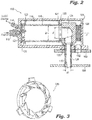
- FIG. 4 schematically indicates the flow of air through system 100 with arrows, and schematically indicates the spray of fuel with stippling.
- An elbow 124 is included with an elbow inlet operatively connected to receive combustion products from the combustion chamber along a longitudinal axis A.
- the inlet diameter d can be between about 25% and 75% of the combustion chamber diameter D. In certain applications, the inlet diameter d is preferably about 50% of the diameter D.
- Elbow 124 has an elbow outlet in fluid communication with the elbow inlet. The elbow outlet is aligned along a radial angle relative to longitudinal axis A. In system 100, the length of the combustion chamber is about twice the diameter D.
- An exhaust tube 126 is connected in fluid communication with the outlet of elbow 124 for issuing combustion gases from exhaust outlet 110 of exhaust tube 126.
- the diameter dl of the outlet passage through exhaust tube 126 can be in a range of about 0.5 to 0.6 times the diameter d of the elbow inlet. All of the wall surfaces in contact with combustion products can be made from high temperature materials which can be metallic, but can preferably be ceramic or ceramic composite materials in certain applications. While elbow 124 has an inlet diameter and an outlet diameter smaller than d, Fig. 5 shows another exemplary embodiment of an elbow 224 in which the inlet and outlet both have the same diameter d.
- Fig. 2 the elbow outlet is aligned along a radial angle relative to longitudinal axis A.
- Fig. 6 shows an ignition system 200 similar to ignition system 100, but with the axis of exhaust outlet 225 is aligned with the longitudinal axis A.
- Housing 208 is mounted to high-pressure casing 202 so that air will flow into housing 208 through radially oriented inlet 232, and outlet 225 is mounted to issue flame into combustor 204.
- Fig. 7 shows the airflow through system 200 schematically with arrows, and shows the spray of fuel into the combustion chamber of system 200 schematically with stippling.
- Swirlers 120 and 122 are not fixed, but instead are centralized by outer tabs 121. Swirlers 120 and 122 seat the cylindrical flow elements in a sliding fashion to prevent or minimize any bending moments being transmitted to the cylinder.
- Exhaust tube 126 and elbow 124 are in contact but allowed to slide relative to one another for relative movement in the direction of longitudinal axis A.
- Exhaust tube 126 and housing 108 are in contact but allowed to slide relative engaged to one another for relative movement in the radial direction relative to longitudinal axis A.
- housing 108, inner wall 116, elbow 124, and exhaust tube 126 can all be made of ceramic or ceramic composite materials. However, those skilled in the art will readily appreciate that any other suitable materials can be used without departing from the scope of this disclosure.
- Housing 108 includes an air inlet 132 for issuing air for combustion into the interior of the housing 108.
- Air inlet 132 and exhaust outlet 110 are aligned to accommodate attachment of housing 108 to the walls of combustor 104 and high-pressure casing 102 to issue flame from exhaust outlet 110 into combustor 104 and to take in compressor discharge air through air inlet 132 from high-pressure casing 102 outboard of combustor 104.
- Ignition system 100 can be retrofitted onto a gas turbine engine to replace a traditional igniter by removing the traditional igniter and connecting air inlet 132 with a modified air passage of the high-pressure casing, and by connecting exhaust tube 126 to issue into the combustor.
- Ignition systems as described above are based around a small combustion volume relative to the main combustor, and remote from the main combustion chamber.
- the housing e.g., housing 108
- the orientation of the internal conduits containing high temperature combustion gases are such as to permit the axis of the main combustion element, e.g., the axial length of housing 108, to lay parallel to the engine axis, reducing the overall diameter of the engine envelope.
- the elbow e.g., elbow 124, and exhaust tube whose axis is normal to the engine axis, allow the engagement with the engine combustor to be similar to conventional ignition devices.
- any suitable modification of this orientation can also be used, for example to allow for improved ignition performance as needed for specific applications.
- a relatively, small amount of metered air enters the combustion volume, e.g., inside housing 108, fed from the pressure of the main engine air supply.
- air swirlers e.g. air swirler 120
- an air flow pattern is developed which enhances stable combustion while a small amount of fuel is injected in the air through an appropriate fuel injector, e.g., injector 112.
- the atomized fuel is ignited by the heat of an electric element or glow plug igniter, e.g., igniter 114, which is fed by low voltage DC electric current.
- the fuel ignites to produce a continuous stream of heat in the small combustor.
- the heat is of sufficient intensity to be able to ignite the fuel nozzle in the main combustor.
- the electric element can be shut off.
- the flame in the small combustor can be left on continuously for the duration of the mission, supplying heat and radicals present in the combustion products to the main combustor at all times.
- the temperature produced by the ignition system does not overwhelm the temperature from the main fuel injectors when stable combustion is achieved.
- the energy from the ignition system rival the energy derived from the main combustor nozzles.
- the impact from the ignition system is diminished at higher engine power and dominates at low engine power. This decoupled phasing and continuous duty helps the ignition system extend the flammability limits over that of a conventional combustor.
- the hot gases from the ignition system can be projected deeply into the main combustor volume. This allows the spray pattern from the main nozzles to be optimized for durability and emissions compared to conventional situations where fuel must be sprayed towards the wall in order to approach a traditional igniter.
- the continuous injection of heat into the main combustor allows for faster, higher quality main combustor ignition at lower, more adverse ignition conditions.
- Conventional fuel injectors require substantial fuel flow at low power to be able to form an atomized spray of sufficient quality to ignite.
- Aerated injectors require substantial air pressure to atomize fuel. At low starting speeds, airflows are low and the relatively high fuel flows are required for atomization produce relatively hot ignition situations when they finally ignite. This is exemplified by torching seen at the exhaust and large quantities of white smoke seen in cold weather starts.
- the ignition of the nozzle e.g., of injector 112
- the resulting flame is capable of igniting low quality sprays in the main combustor, speeding up engine ignition and reducing the overall temperature experienced during the main ignition sequence. This can prolong the life of the engine hot end components.
- the ignition system can remain on continuously during a mission, protecting the main combustor from flame out. Its power can be controlled to vary with engine conditions through the fuel flow delivered to the ignition system. As such, it is capable of withstanding large excursions in engine conditions thereby assisting the main combustor.
- the ignition system can utilize relatively low, DC power electric elements for ignition. These igniter devices are not prone to contamination from carbon deposits and are not prone to wetting or icing. They do not require high voltage cables and connectors, allowing for a lighter, more dependable delivery of ignition energy compared to higher voltage traditional igniters. They also emit significantly less electromagnetic interference to neighboring electronic equipment.
- the size of the combustion chamber should be compact enough to easily be accommodated in an engine envelope and to utilize a small amount of fuel but be large enough to support a strong, stable flame. It has been found that using a cylindrical geometry with an approximate diameter of 1.5 inches (about 3.8 centimeters) can meet these objectives for certain typical applications.
- An exemplary method of ignition for a combustor in a gas turbine engine includes initiating a fuel and airflow through the fuel injector of an ignition system as described above. The method also includes igniting the fuel and airflow with the igniter, e.g., igniter 112, and igniting a fuel and airflow in a combustor with the flame from the exhaust outlet of the ignition system.
- An exemplary method of combustion stabilization for a combustor in a gas turbine engine includes detecting a combustion instability in a combustor and issuing a flame from the exhaust outlet of an ignition system as described above into the combustor to stabilize combustion in the combustor.
- the method can further include increasing flame strength from the exhaust outlet of the ignition system in response to weak flame conditions in the combustor, and decreasing flame strength from the exhaust outlet of the ignition system in response to stable flame conditions in the combustor. While shown and described in the exemplary context of gas turbine engines, those skilled in the art will readily appreciate that ignition systems in accordance with this disclosure can be used in any other suitable application without departing from the scope of this disclosure.
- Igniter assembly 150 receives a compressor airflow and fuel flow, and mixes the flows within an igniter chamber. Electric current is provided to either or both a channel A and a channel B of igniter assembly 150 which are connected to a remote power source by suitable electrical cable.
- Igniter assembly 150 is configured and adapted for integration into ignition system 100 for establishing and sustaining combustion within a gas turbine combustor. Igniter assembly 150 attaches externally to high-pressure combustor casing 108 externally, thereby providing access for maintenance or monitoring during operation. Exhaust tube 126 of igniter assembly 150 is similar in size to conventional igniters, potentially rendering igniter assembly 150 suitable for new engine applications, ease of 'design in' into derivatives of existing engines, and as a possible upgrade or retrofit of existing engines. Igniter assembly 150 protrudes through a floating seal into combustor casing 116, potentially accommodating geometry changes associated with startup and shutdown of the gas turbine combustor to which it is coupled.
- Compressed air from the compressor section of a gas turbine is guided as a continuous air flow through an oxidizer conduit 152 (shown in Fig. 17 ) of igniter assembly 150 device for mixing with fuel provided through a fuel conduit 154 (also shown in Fig. 17 ).
- the mixture is ignited and ducted into the main combustion chamber to provide an ignition source to the main fuel flow within combustor.
- the device is decoupled from the main combustor, can be made to burn hot (i.e. at a higher temperature and/or higher fuel consumption rate) when power to the engine is reduced, and can be turned down to burn cooler (i.e. at a higher temperature and/or lower fuel consumption rate) when power from the engine is at its highest.
- a combustion volume of the ignition system is isolated from the main combustor and as such is under an environment suitable for combustion under different conditions than the main combustor.
- ignition system 100 to ignite under conditions that may arise at very high altitude and which are more readily addressed through the combustion conditions within the ignition device than in the large combustor with conventional ignition.
- igniter assembly 100 provides adequate sealing against internal engine pressure through flanges and fasteners. Air, fuel, and electrical provisions are provided externally to ignition system which are protected thermally from the high temperatures of gas turbine combustor environs.
- igniter assembly 150 is shown in a cross-sectional side elevation view.
- An interior of igniter assembly 150 defines a combustion chamber 156 configured for containing the combustion products and exhausting the combustion products into the main combustor chamber.
- a head assembly 160 is configured for sealing the interior of the combustion chamber and is provisioned for seating fuel, air and ignition structures.
- a head block 162 with a cover 164 provides threaded connections for attachments to a power source, i.e. channel A and channel B. These connections engage external metallic shields of the respective power cables for purposes of providing a path to the system electrical ground.
- Cover 164 grounds igniters 166, e.g. glow plugs, through direct contact with head block 162 through a fastener 158.
- a separate ground wire and ground wire fastener performs this function.
- grounding can be through a ground wire attached between the block and the cap (not shown for clarity purposes).
- Head block 162 defines an issue axis 170 extending through issue aperture 168 and about which igniters 166 are disposed.
- Igniters 166 are arranged obliquely with respect to an issue axis 170 and about issue axis 170 such that, irrespective of system orientation, ignition flame issues from igniter assembly 150 into the combustion of chamber of gas turbine. This provides for stabilization of a flame within the combustor by providing concentrated thermal power to fuel issuing from head block 162 independent of gravitational effects due to system orientation. Any orientation of the igniter assembly 150 will therefore provide opportunity for fuel to approach at least one hot igniter member 174.
- Igniters 166 are further arranged to be far enough from issue axis 170 such that fuel issuing from issue aperture 168 does not wet each igniter member sufficiently to cool the igniter members sufficiently to potentially prevent ignition, yet is close enough to issue axis 170 such that adequate ignition and flame stabilization is realized.
- igniters 166 are disposed in an offset conical pattern which allow igniter members 166 elements to approach issue axis 170 at a desired distal (i.e. an optimal distance) for example, without interfering or colliding with one another. Igniter members 166 are also arranged to be independent of gravitation forces which may be imposed on low flowing fuel streams biasing the stream in one direction.
- FIG. 10 an end of igniter assembly 150 is shown.
- Cover 164 shields the internal components located under the cover and provides support for electrical connectors for channel A and channel B. Separate power input cables for channel A and channel B connect to the electrical connectors disposed on cover 164.
- Fastener 158 is centrally located to fasten cover 164 to head block 162, and provide an electrical ground path to ground through cover 164 to metal sheaths of cables coupled to the electrical connectors.
- Head block fasteners 172 separately arranged about the periphery of head block 162, couple head block 1562 to housing 108 (shown in Fig. 8 ). This provided for ease of service as igniters 166 are accessible for replacement without removing head block 162 from housing 108.
- igniter assembly 150 is shown in a side elevational view.
- Igniter assembly 150 includes six igniters that are concentrically arranged such that respective igniter members 166 are skew with respect to issue axis 170. This allows igniters 166 to ignite spray issuing from issue aperture 168 but not be cooled by the spray or to interfere with the spray during operation.
- igniter assembly further includes a thermal barrier plate 176 arranged adjacent (or on) a face oriented combustion chamber 156 for shielding components from heat generated within combustion chamber 156.
- Insulating plate 176 can be constructed from a ceramic material, for example.
- head block 162 is shown with igniters 166 installed.
- Head block 162 defines a plurality of coolant grooves 178 defined in a surface head block 162 facing combustion chamber 156. Coolant grooves 178 are fluidly coupled with issue aperture 168 so as to receive and distribute a flow of coolant across the face of head block 162, such as with a baffle structure.
- insulating plate 176 defines a plurality of circumferential recesses 180 configured to provide an inlet for the coolant flow radially offset from issue aperture 168. Coolant grooves 178 and insulating 176 cooperate to direct coolant issuing from issue aperture 168 radially, across the face of head block 162, thereby cooling head block 162.
- coolant grooves 178 define radial channels 179.
- coolant channels 179 can have other geometries and remain within the scope of the present disclosure.
- head block 162 is shown in backside perspective and cross-section perspective views.
- igniter 166 e.g. ceramic glow plugs
- issue aperture 168 the plugs are threadably received within head block 162.
- Ceramic elements of the igniters 166 are brazed into metallic jackets which form threaded connectors and which electrically ground the elements to the main block.
- the interface between each respective metallic jackets and head block 162 is sufficiently large to permit heat to be extracted from the ceramic/metallic braze interface region into head block 162 to prevent the braze joint from thermally degrading.
- Head block 162 seals an end of combustion chamber 156 (shown in Fig. 8 ). Head block 162 defines flanges and is of suitable thickness for sealing combustion chamber 156. As shown, head block 162 defines a plurality of grooves 180 for securing head block 162 of the torch body with fasteners using a spider manifold 182 (shown in Fig. 17 ). In embodiments, grooves 180 are oversized with respect to spider manifold 182, thereby reducing heat transfer between head block 162 and spider manifold 182. Igniters 166 engage head block 162 with suitable threads for sealing combustion gases houses within combustion chamber 156.
- Igniters 166 are independently operable in two separate banks of three, e.g. as a 'channel A' and a 'channel B'. As will be appreciated by those skilled in the art, this provides for operation of one bank as flame detector while the other is used as heating elements for ignition. For example, in operational circumstances where ignition is extremely difficult due to cold fuel conditions, all plugs can be selected to be energized to provide a very hot concentrated zone which can vaporize and ignite the fuel. Both banks can also be cooperatively operated, such as when additional heat is necessary to warm fuel entering combustion chamber 156, such as during operation at extreme altitude for example. Similarly, igniters in a powered off state can develop a carbon coating during operation while de-energized.
- igniters having a solid ceramic construction instead of conventional glow plugs with a metallic filament which can withstand very high operating temperatures for extended periods of time without deteriorating provides increased operational reliability.
- spider manifold 182 is shown from the perspective of head block 162.
- Spider manifold 182 includes a centrally arranged nozzle chamber 184 including issue aperture 168.
- a plurality of arms extend radially from nozzle chamber 184, one arm including a fuel conduit 186, one arm including an oxidizer conduit 188, one arm including a supplemental air conduit 190, and in at least two arms forming coupling arms 192.
- Fuel conduit 186 is configured and adapted for connection to a fuel source on one end, and is fluidly coupled to nozzle chamber 184 on its other end.
- Oxidizer conduit 188 is fluidly coupled to an oxidizer source, e.g. air, on one end, and fluid couples to nozzle chamber 184 on its other end.
- Coupling arms 192 structurally couple to nozzle chamber 184 on one end, and are configured and adapted to receive fasteners for coupling spider manifold 182 to housing 108, such as by receiving a fastener at a respective end.
- Spider manifold 182 provides a fuel connector and fuel gallery for the device, external air connectors and air galleries for the device, and a central nozzle chamber 184 configured and adapted to seat a fuel atomization element (shown in Fig. 21 ).
- spider manifold 182 is shown attached to head block 162.
- Fuel conduit 186, oxidizer conduit 188, supplemental air conduit 190, and coupling arms 192 are received within respective grooves 180 defined within head block 162.
- External fluid connections e.g. fuel, oxidizer, coolant
- Connections with respective conduits can be made from below, i.e. from the combustor side of spider manifold 182 as shown in Fig. 19 , or from the top side, i.e. from opposite the combustor side of spider manifold 182 as shown in Fig. 20 , as suitable for a given application.
- different numbers of conduits can be provided as suitable for a given application, such as to supply greater volume of fuel, air or coolant for example.
- igniter assembly 150 is shown.
- Fuel conduit 186 conveys fuel to the nozzle chamber 184.
- Fuel conduit 186 (as well as oxidizer conduit 188, supplemental conduit 190 and coupling arms 192) engages head block 162 so as to reduce heat transfer between the elements. This is done by selectively oversizing grooves 180 such that voids 196 and seals 194 are formed between spider manifold 180 and head block 162 along respective lengths of fuel conduit 186, oxidizer conduit 188, supplemental air conduit 190, and coupling arms 192.
- Oxidizer e.g. air
- Oxidizer conduit 188 is admitted into nozzle chamber 184 from oxidizer conduit 188 and has oxidizer inlet arranged above a fuel distribution element.
- Issue aperture 168 is relatively small, and in embodiments is between about 0.05 inches (1.27 millimeters) to about 0.07 inches (1.78 millimeters), thereby limiting backflow of combustion gases from combustion chamber 156 into head block 162.
- Head block 162 additionally includes insulating plate 176 which shields head block 162 from combustion environment. As described above, cooling air to be admitted behind the ceramic plate to further limit the amount of heat that can flow into the bulkhead and then into the fuel conveying manifold.
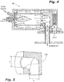
- electrical interconnects 198 are shown.
- electrical interconnect includes an igniter socket, a channel socket, and bridging element spanning between the igniter and channel sockets.
- the igniter socket seats on an end of igniter 166 and is oriented, e.g. clocked radially about igniter 166, so as to align with first insulating body 140 (shown in Fig. 22D ) and second insulating plate 142 (shown in Fig. 23C ), and electrically connects with one of first feed body 144 (shown in Fig. 23A ) and second feed body 146.
- first insulating body connects to igniter assembly 150 so as to electrically insulate each of electrical interconnects 198 from one another, and is constructed from a temperature resistant insulating material such as ceramic for example.
- first feed body 144 is shown. As shown in Fig. 23A , first feed body 144 includes an input prong, a plurality of output prongs, and a circumferentially extending conductive body coupling the output prongs to the input prong. As shown in Fig. 23B , first feed body 140 seats on first insulating body 140 and electrically connects to a plurality of the electrical interconnects 198. This groups igniters into a bank, and in the illustrated embodiment, groups every other igniter 166 in the set of six illustrated into a first bank of three igniters. As shown in Fig.
- second insulating body seats over first feed body 144, and is similar in construction to first insulating body 140.
- the channel 'A' input of the first feed body extends through first insulating body, thereby providing electrical connection to the first bank of igniters.
- Second feed body 146 is similar in construction to first feed body 144, and additionally include a lunate cutout 149.
- second feed body 146 seats on second insulating body 142 such that the channel A input of first feed body 144 extends through second feed body 146 in electrical isolation therefrom.
- third insulating body 148 seats over second insulating body 142 and second feed body 146, and in cooperation with flanges disposed about peripheries of first insulating body 140 and second insulating body 142, presents an insulated stack to cover 164. This enables cover 164 to mechanically fix the insulating bodies and conductive bodies in place and act as a conductive path to ground as described above.
Landscapes
- Engineering & Computer Science (AREA)
- Chemical & Material Sciences (AREA)
- Combustion & Propulsion (AREA)
- Mechanical Engineering (AREA)
- General Engineering & Computer Science (AREA)
- Ignition Installations For Internal Combustion Engines (AREA)
- Spark Plugs (AREA)
Claims (13)
- Kopfbaugruppe (160) für eine Zündanlage (100), umfassend:einen Kopfblock (162) mit einer Ausgabeöffnung (168) und eine Ausgabeachse (170) definierend, wobei der Kopfblock (162) konfiguriert und ausgelegt ist, um dichtbar an eine Zünderbrennkammer (156) zu koppeln; undeine Vielzahl von Zündern (166), die in dem Kopfblock (162) liegen und um die Ausgabeöffnung (168) angeordnet sind, wobei jeder der Zünder (166) ein Zündelement aufweist, das schräg in Bezug auf die Ausgabeachse (170) angeordnet ist, um Kraftstoff zu zünden, der die Ausgabeöffnung (168) verlässt, unabhängig von der Ausrichtung der Zündanlage (100), wobei jedes der Zündelemente (166) versetzt in Bezug auf die Ausgabeachse (170) ist, dadurch gekennzeichnet, dassder Kopfblock (162) eine Vielzahl von Schlitzen (180) definiert, die die Ausgabeöffnung (168) schneiden, und ferner umfassend einen Spinnenverteiler (182), der in der Vielzahl von Schlitzen (180), die durch die Kopfblockschlitze (180) definiert sind, angeordnet ist.
- Kopfbaugruppe (160) nach einem vorhergehenden Anspruch, wobei die Vielzahl von Zündern (166) einen ersten Zünder und zweiten Zünder beinhaltet, wobei der erste und zweite Zünder kollektiv zur Zündung bedienbar sind und unabhängig zur Zündung und Flammenerfassung bedienbar sind.
- Kopfbaugruppe (160) nach Anspruch 2, ferner beinhaltend eine erste Bank aus drei Zündern und eine zweite Bank aus drei Zündern, wobei die Zünder um die Ausgabeöffnung (168) angeordnet sind, sodass jeder zweite Zünder an eine erste und zweite Stromquelle gekoppelt ist.
- Kopfbaugruppe (160) nach Anspruch 1, wobei der Spinnenverteiler (182) eine einstückige, sich radial erstreckende Kraftstoffleitung (186) definiert, die fluidisch an die Ausgabeöffnung (168) gekoppelt ist; oder
wobei der Spinnenverteiler (182) eine einstückige, sich radial erstreckende Oxidationsleitung (188) definiert, die fluidisch an die Ausgabeöffnung (168) gekoppelt ist. - Kopfbaugruppe (160) nach Anspruch 4, wobei der Spinnenverteiler (182) eine einstückige Kühlmittelleitung beinhaltet, die konfiguriert und ausgelegt ist, um Kühlmittel an eine Fläche des Kopfblocks (162) zu liefern.
- Kopfbaugruppe (160) nach einem vorhergehenden Anspruch, ferner beinhaltend einen isolierenden Körper (140), der auf dem Kopfblock (162) liegt, eine Vielzahl von Verbindungsöffnungen aufweisend, um die Zünder (166) elektrisch mit einer Stromquelle zu verbinden.
- Kopfbaugruppe (160) nach Anspruch 6, ferner beinhaltend einen leitenden Überbrückungskörper, der eine Vielzahl von leitenden Abschnitten aufweist, die sich durch eine erste Vielzahl von Verbindungsöffnungen definiert durch den isolierenden Körper erstrecken.
- Kopfbaugruppe (160) nach Anspruch 6, wobei der isolierende Körper ein erster isolierender Körper (140) ist und ferner beinhaltend einen zweiten isolierenden Körper (142), der gegen eine Fläche des leitenden Überbrückungskörpers angeordnet ist.
- Kopfbaugruppe (160) nach Anspruch 8, wobei der leitende Überbrückungskörper ein erster leitender Überbrückungskörper ist und ferner beinhaltend einen zweiten leitenden Überbrückungskörper, der eine Vielzahl von leitenden Abschnitten aufweist, die sich durch eine zweite Vielzahl von Verbindungsöffnungen definiert durch die isolierenden Körper erstrecken, und vorzugsweise ferner beinhaltend eine Vielzahl von elektrischen Verbindungen (198), die sich von Enden der Zünder (166) zu einem von dem ersten und zweiten leitenden Überbrückungskörper radial nach innen erstrecken.
- Kopfbaugruppe (160) nach Anspruch 5, ferner umfassend einen isolierenden Körper, der an eine Fläche des Kopfblocks (162) gekoppelt und fluidisch an die Kühlmittelleitung gekoppelt ist.
- Kopfbaugruppe (160) nach einem vorhergehenden Anspruch, ferner beinhaltend eine isolierende Platte (176), die benachbart zu einer Innenfläche des Kopfblocks (162) angeordnet ist, wobei die isolierende Platte (176) eine zentrale Ausgabeöffnung und eine Vielzahl von radial angeordneten Zünderöffnungen definiert, die konfiguriert sind, um Zünder in einer außeraxialen, versetzten Anordnung aufzunehmen.
- Kopfbaugruppe (160) nach Anspruch 11, wobei eine Fläche des Kopfblocks (162) gegenüber der isolierenden Platte (176) eine Vielzahl von Kühlkanälen definiert, um Kühlmittel zwischen dem Kopfblock (162) und isolierenden Block zu strömen.
- Kopfbaugruppe (160) nach einem vorhergehenden Anspruch, ferner beinhaltend eine Abdeckung (164), die durch eine Befestigung (158) an den Kopfblock (162) gekoppelt ist, wobei die Befestigung (158) einen Massereferenzanschluss für die Zünder (166) bereitstellt.
Applications Claiming Priority (3)
| Application Number | Priority Date | Filing Date | Title |
|---|---|---|---|
| US13/917,053 US9080772B2 (en) | 2013-06-13 | 2013-06-13 | Continuous ignition |
| US201361900644P | 2013-11-06 | 2013-11-06 | |
| US14/169,452 US9567912B2 (en) | 2013-06-13 | 2014-01-31 | Continuous ignition systems |
Publications (2)
| Publication Number | Publication Date |
|---|---|
| EP2813683A1 EP2813683A1 (de) | 2014-12-17 |
| EP2813683B1 true EP2813683B1 (de) | 2018-09-05 |
Family
ID=50943149
Family Applications (1)
| Application Number | Title | Priority Date | Filing Date |
|---|---|---|---|
| EP14172327.0A Active EP2813683B1 (de) | 2013-06-13 | 2014-06-13 | Kontinuierliche Zündanlagen |
Country Status (2)
| Country | Link |
|---|---|
| US (1) | US9567912B2 (de) |
| EP (1) | EP2813683B1 (de) |
Cited By (1)
| Publication number | Priority date | Publication date | Assignee | Title |
|---|---|---|---|---|
| US11150066B2 (en) | 2019-05-10 | 2021-10-19 | Hamilton Sundstrand Corporation | Multi-use torpedo propulsion system starter |
Families Citing this family (31)
| Publication number | Priority date | Publication date | Assignee | Title |
|---|---|---|---|---|
| US20130247579A1 (en) * | 2012-03-26 | 2013-09-26 | General Electric Company | Method of startup control for a gas turbine system operating in a fired deceleration shutdown process mode |
| US9803554B2 (en) * | 2013-08-12 | 2017-10-31 | Unison Industries, Llc | Fuel igniter assembly having heat-dissipating element and methods of using same |
| US20170059165A1 (en) | 2015-08-28 | 2017-03-02 | Rolls-Royce High Temperature Composites Inc. | Cmc cross-over tube |
| US11692488B2 (en) | 2020-11-04 | 2023-07-04 | Delavan Inc. | Torch igniter cooling system |
| US11473505B2 (en) * | 2020-11-04 | 2022-10-18 | Delavan Inc. | Torch igniter cooling system |
| US20220136446A1 (en) * | 2020-11-04 | 2022-05-05 | Delavan Inc. | Temperature sensing for torch ignition systems |
| US11608783B2 (en) * | 2020-11-04 | 2023-03-21 | Delavan, Inc. | Surface igniter cooling system |
| US11635027B2 (en) | 2020-11-18 | 2023-04-25 | Collins Engine Nozzles, Inc. | Fuel systems for torch ignition devices |
| CN112412629B (zh) * | 2020-11-27 | 2022-09-20 | 中国航发四川燃气涡轮研究院 | 一种可调伸缩式自动控制点火器装置 |
| US11226103B1 (en) | 2020-12-16 | 2022-01-18 | Delavan Inc. | High-pressure continuous ignition device |
| US11421602B2 (en) | 2020-12-16 | 2022-08-23 | Delavan Inc. | Continuous ignition device exhaust manifold |
| US20220195935A1 (en) * | 2020-12-17 | 2022-06-23 | Delavan Inc. | Axially oriented internally mounted continuous ignition device: reverse flow axial orientation |
| US11635210B2 (en) | 2020-12-17 | 2023-04-25 | Collins Engine Nozzles, Inc. | Conformal and flexible woven heat shields for gas turbine engine components |
| US11754289B2 (en) | 2020-12-17 | 2023-09-12 | Delavan, Inc. | Axially oriented internally mounted continuous ignition device: removable nozzle |
| US11486309B2 (en) * | 2020-12-17 | 2022-11-01 | Delavan Inc. | Axially oriented internally mounted continuous ignition device: removable hot surface igniter |
| US12092333B2 (en) | 2020-12-17 | 2024-09-17 | Collins Engine Nozzles, Inc. | Radially oriented internally mounted continuous ignition device |
| US20220195933A1 (en) * | 2020-12-17 | 2022-06-23 | Delavan Inc. | Radially oriented internally mounted continuous ignition device |
| US11209164B1 (en) | 2020-12-18 | 2021-12-28 | Delavan Inc. | Fuel injector systems for torch igniters |
| US11680528B2 (en) * | 2020-12-18 | 2023-06-20 | Delavan Inc. | Internally-mounted torch igniters with removable igniter heads |
| US11286862B1 (en) | 2020-12-18 | 2022-03-29 | Delavan Inc. | Torch injector systems for gas turbine combustors |
| US11566565B2 (en) * | 2020-12-23 | 2023-01-31 | Collins Engine Nozzles, Inc. | Access hatch for internally mounted torch ignitor |
| US11708793B2 (en) * | 2020-12-23 | 2023-07-25 | Collins Engine Nozzles, Inc. | Torch ignitors with gas assist start |
| US11543130B1 (en) * | 2021-06-28 | 2023-01-03 | Collins Engine Nozzles, Inc. | Passive secondary air assist nozzles |
| US11674445B2 (en) * | 2021-08-30 | 2023-06-13 | Collins Engine Nozzles, Inc. | Cooling for continuous ignition devices |
| US11674446B2 (en) * | 2021-08-30 | 2023-06-13 | Collins Engine Nozzles, Inc. | Cooling for surface ignitors in torch ignition devices |
| US20230060569A1 (en) * | 2021-08-30 | 2023-03-02 | Delavan Inc. | Self-cleaning for torch ignitors |
| US11549441B1 (en) * | 2021-10-12 | 2023-01-10 | Collins Engine Nozzles, Inc. | Fuel injectors with torch ignitors |
| US11773784B2 (en) * | 2021-10-12 | 2023-10-03 | Collins Engine Nozzles, Inc. | Fuel injectors with torch ignitors |
| DE102022203965A1 (de) * | 2022-04-25 | 2023-10-26 | Robert Bosch Gesellschaft mit beschränkter Haftung | Brenner für ein Abgasnachbehandlungssystem, Abgasnachbehandlungssystem für eine Brennkraftmaschine |
| CN117091160B (zh) * | 2022-05-11 | 2026-04-21 | 通用电气公司 | 用于燃气涡轮的燃烧器的点火器外壳 |
| CN116146352B (zh) * | 2023-04-23 | 2023-08-18 | 中国空气动力研究与发展中心空天技术研究所 | 超燃冲压发动机展向非均匀燃料脉冲喷注装置及使用方法 |
Citations (1)
| Publication number | Priority date | Publication date | Assignee | Title |
|---|---|---|---|---|
| US20050208446A1 (en) * | 2000-02-11 | 2005-09-22 | Jayne Michael E | Furnace using plasma ignition system for hydrocarbon combustion |
Family Cites Families (6)
| Publication number | Priority date | Publication date | Assignee | Title |
|---|---|---|---|---|
| GB717755A (en) | 1950-07-06 | 1954-11-03 | British Thomson Houston Co Ltd | Improvements in and relating to ignition systems |
| US6298659B1 (en) | 1999-03-24 | 2001-10-09 | Orbital Technologies Corporation | Vortex flow field and apparatus and method for producing the same |
| JP3634325B2 (ja) | 2002-05-30 | 2005-03-30 | 住重機器システム株式会社 | 超音速ジェットバーナー |
| ITMO20060110A1 (it) | 2006-03-31 | 2007-10-01 | Nbp S R L | Bruciatore |
| DE102011018846A1 (de) * | 2011-01-19 | 2012-07-19 | GETAS GESELLSCHAFT FüR THERMODYNAMISCHE ANTRIEBSSYSTEME MBH | Axialkolbenmotor sowie Verfahren zum Betrieb eines Axialkolbenmotors |
| WO2014043343A1 (en) | 2012-09-14 | 2014-03-20 | Eclipse, Inc. | Dual mode burner yielding low nox emission |
-
2014
- 2014-01-31 US US14/169,452 patent/US9567912B2/en active Active
- 2014-06-13 EP EP14172327.0A patent/EP2813683B1/de active Active
Patent Citations (1)
| Publication number | Priority date | Publication date | Assignee | Title |
|---|---|---|---|---|
| US20050208446A1 (en) * | 2000-02-11 | 2005-09-22 | Jayne Michael E | Furnace using plasma ignition system for hydrocarbon combustion |
Cited By (1)
| Publication number | Priority date | Publication date | Assignee | Title |
|---|---|---|---|---|
| US11150066B2 (en) | 2019-05-10 | 2021-10-19 | Hamilton Sundstrand Corporation | Multi-use torpedo propulsion system starter |
Also Published As
| Publication number | Publication date |
|---|---|
| EP2813683A1 (de) | 2014-12-17 |
| US20140366505A1 (en) | 2014-12-18 |
| US9567912B2 (en) | 2017-02-14 |
Similar Documents
| Publication | Publication Date | Title |
|---|---|---|
| EP2813683B1 (de) | Kontinuierliche Zündanlagen | |
| EP2813684B1 (de) | Kontinuierliche Zündung | |
| EP4015912B1 (de) | Fackelzündungssystem für einen gasturbinenmotor und verfahren zum betreiben eines solchen systems | |
| US6915638B2 (en) | Nozzle with fluted tube | |
| US11428413B2 (en) | Fuel injection module for segmented annular combustion system | |
| US8181440B2 (en) | Arrangement of a semiconductor-type igniter plug in a gas turbine engine combustion chamber | |
| EP3995742B1 (de) | Kühlsystem für funkenzünder | |
| US10584876B2 (en) | Micro-channel cooling of integrated combustor nozzle of a segmented annular combustion system | |
| EP4019838B1 (de) | Fackelzündersystem fur eine gasturbinenbrennkammer und verfahren zum betreiben eines solches system | |
| RU2482305C2 (ru) | Топливная форсунка с изолирующей воздушной завесой | |
| JP5762424B2 (ja) | タービンのエンジン燃焼室のための多点式燃料噴射器 | |
| EP3073197B1 (de) | Systeme zur erzeugung einer dichtung um einen flüssigbrennstoffinjektor in einem gasturbinenmotor | |
| US6354085B1 (en) | Fuel injector with a fuel filter arrangement for a gas turbine engine | |
| EP4015907B1 (de) | Brennkammer eines gasturbinenmotors und verfahren zum ersetzen eines oberflächenzünders eines fackelzünders davon | |
| EP3995741B1 (de) | Fackelzünder mit kühlsystem | |
| US20140338342A1 (en) | Fuel injector having an ignitor for igniting a combustor of a gas turbine | |
| CA2776162C (en) | Integrated fuel nozzle and ignition assembly for gas turbine engines | |
| JP5616456B2 (ja) | タービンエンジンの燃焼室のための多点式噴射装置 | |
| EP4166847B1 (de) | Kraftstoffinjektoren mit fackelzündern | |
| US20220195939A1 (en) | Tangentially mounted torch ignitors | |
| CN102980203A (zh) | 一种气态燃料旋流一体化点火器 |
Legal Events
| Date | Code | Title | Description |
|---|---|---|---|
| 17P | Request for examination filed |
Effective date: 20140613 |
|
| AK | Designated contracting states |
Kind code of ref document: A1 Designated state(s): AL AT BE BG CH CY CZ DE DK EE ES FI FR GB GR HR HU IE IS IT LI LT LU LV MC MK MT NL NO PL PT RO RS SE SI SK SM TR |
|
| AX | Request for extension of the european patent |
Extension state: BA ME |
|
| PUAI | Public reference made under article 153(3) epc to a published international application that has entered the european phase |
Free format text: ORIGINAL CODE: 0009012 |
|
| R17P | Request for examination filed (corrected) |
Effective date: 20150615 |
|
| RBV | Designated contracting states (corrected) |
Designated state(s): AL AT BE BG CH CY CZ DE DK EE ES FI FR GB GR HR HU IE IS IT LI LT LU LV MC MK MT NL NO PL PT RO RS SE SI SK SM TR |
|
| STAA | Information on the status of an ep patent application or granted ep patent |
Free format text: STATUS: EXAMINATION IS IN PROGRESS |
|
| 17Q | First examination report despatched |
Effective date: 20170705 |
|
| GRAP | Despatch of communication of intention to grant a patent |
Free format text: ORIGINAL CODE: EPIDOSNIGR1 |
|
| STAA | Information on the status of an ep patent application or granted ep patent |
Free format text: STATUS: GRANT OF PATENT IS INTENDED |
|
| INTG | Intention to grant announced |
Effective date: 20180319 |
|
| GRAS | Grant fee paid |
Free format text: ORIGINAL CODE: EPIDOSNIGR3 |
|
| GRAA | (expected) grant |
Free format text: ORIGINAL CODE: 0009210 |
|
| STAA | Information on the status of an ep patent application or granted ep patent |
Free format text: STATUS: THE PATENT HAS BEEN GRANTED |
|
| AK | Designated contracting states |
Kind code of ref document: B1 Designated state(s): AL AT BE BG CH CY CZ DE DK EE ES FI FR GB GR HR HU IE IS IT LI LT LU LV MC MK MT NL NO PL PT RO RS SE SI SK SM TR |
|
| REG | Reference to a national code |
Ref country code: GB Ref legal event code: FG4D |
|
| REG | Reference to a national code |
Ref country code: CH Ref legal event code: EP |
|
| REG | Reference to a national code |
Ref country code: AT Ref legal event code: REF Ref document number: 1038079 Country of ref document: AT Kind code of ref document: T Effective date: 20180915 |
|
| REG | Reference to a national code |
Ref country code: IE Ref legal event code: FG4D |
|
| REG | Reference to a national code |
Ref country code: DE Ref legal event code: R096 Ref document number: 602014031625 Country of ref document: DE |
|
| REG | Reference to a national code |
Ref country code: NL Ref legal event code: MP Effective date: 20180905 |
|
| REG | Reference to a national code |
Ref country code: LT Ref legal event code: MG4D |
|
| PG25 | Lapsed in a contracting state [announced via postgrant information from national office to epo] |
Ref country code: SE Free format text: LAPSE BECAUSE OF FAILURE TO SUBMIT A TRANSLATION OF THE DESCRIPTION OR TO PAY THE FEE WITHIN THE PRESCRIBED TIME-LIMIT Effective date: 20180905 Ref country code: RS Free format text: LAPSE BECAUSE OF FAILURE TO SUBMIT A TRANSLATION OF THE DESCRIPTION OR TO PAY THE FEE WITHIN THE PRESCRIBED TIME-LIMIT Effective date: 20180905 Ref country code: NO Free format text: LAPSE BECAUSE OF FAILURE TO SUBMIT A TRANSLATION OF THE DESCRIPTION OR TO PAY THE FEE WITHIN THE PRESCRIBED TIME-LIMIT Effective date: 20181205 Ref country code: FI Free format text: LAPSE BECAUSE OF FAILURE TO SUBMIT A TRANSLATION OF THE DESCRIPTION OR TO PAY THE FEE WITHIN THE PRESCRIBED TIME-LIMIT Effective date: 20180905 Ref country code: GR Free format text: LAPSE BECAUSE OF FAILURE TO SUBMIT A TRANSLATION OF THE DESCRIPTION OR TO PAY THE FEE WITHIN THE PRESCRIBED TIME-LIMIT Effective date: 20181206 Ref country code: LT Free format text: LAPSE BECAUSE OF FAILURE TO SUBMIT A TRANSLATION OF THE DESCRIPTION OR TO PAY THE FEE WITHIN THE PRESCRIBED TIME-LIMIT Effective date: 20180905 Ref country code: BG Free format text: LAPSE BECAUSE OF FAILURE TO SUBMIT A TRANSLATION OF THE DESCRIPTION OR TO PAY THE FEE WITHIN THE PRESCRIBED TIME-LIMIT Effective date: 20181205 |
|
| REG | Reference to a national code |
Ref country code: AT Ref legal event code: MK05 Ref document number: 1038079 Country of ref document: AT Kind code of ref document: T Effective date: 20180905 |
|
| PG25 | Lapsed in a contracting state [announced via postgrant information from national office to epo] |
Ref country code: LV Free format text: LAPSE BECAUSE OF FAILURE TO SUBMIT A TRANSLATION OF THE DESCRIPTION OR TO PAY THE FEE WITHIN THE PRESCRIBED TIME-LIMIT Effective date: 20180905 Ref country code: AL Free format text: LAPSE BECAUSE OF FAILURE TO SUBMIT A TRANSLATION OF THE DESCRIPTION OR TO PAY THE FEE WITHIN THE PRESCRIBED TIME-LIMIT Effective date: 20180905 Ref country code: HR Free format text: LAPSE BECAUSE OF FAILURE TO SUBMIT A TRANSLATION OF THE DESCRIPTION OR TO PAY THE FEE WITHIN THE PRESCRIBED TIME-LIMIT Effective date: 20180905 |
|
| PG25 | Lapsed in a contracting state [announced via postgrant information from national office to epo] |
Ref country code: IT Free format text: LAPSE BECAUSE OF FAILURE TO SUBMIT A TRANSLATION OF THE DESCRIPTION OR TO PAY THE FEE WITHIN THE PRESCRIBED TIME-LIMIT Effective date: 20180905 Ref country code: RO Free format text: LAPSE BECAUSE OF FAILURE TO SUBMIT A TRANSLATION OF THE DESCRIPTION OR TO PAY THE FEE WITHIN THE PRESCRIBED TIME-LIMIT Effective date: 20180905 Ref country code: PL Free format text: LAPSE BECAUSE OF FAILURE TO SUBMIT A TRANSLATION OF THE DESCRIPTION OR TO PAY THE FEE WITHIN THE PRESCRIBED TIME-LIMIT Effective date: 20180905 Ref country code: NL Free format text: LAPSE BECAUSE OF FAILURE TO SUBMIT A TRANSLATION OF THE DESCRIPTION OR TO PAY THE FEE WITHIN THE PRESCRIBED TIME-LIMIT Effective date: 20180905 Ref country code: CZ Free format text: LAPSE BECAUSE OF FAILURE TO SUBMIT A TRANSLATION OF THE DESCRIPTION OR TO PAY THE FEE WITHIN THE PRESCRIBED TIME-LIMIT Effective date: 20180905 Ref country code: ES Free format text: LAPSE BECAUSE OF FAILURE TO SUBMIT A TRANSLATION OF THE DESCRIPTION OR TO PAY THE FEE WITHIN THE PRESCRIBED TIME-LIMIT Effective date: 20180905 Ref country code: IS Free format text: LAPSE BECAUSE OF FAILURE TO SUBMIT A TRANSLATION OF THE DESCRIPTION OR TO PAY THE FEE WITHIN THE PRESCRIBED TIME-LIMIT Effective date: 20190105 Ref country code: AT Free format text: LAPSE BECAUSE OF FAILURE TO SUBMIT A TRANSLATION OF THE DESCRIPTION OR TO PAY THE FEE WITHIN THE PRESCRIBED TIME-LIMIT Effective date: 20180905 Ref country code: EE Free format text: LAPSE BECAUSE OF FAILURE TO SUBMIT A TRANSLATION OF THE DESCRIPTION OR TO PAY THE FEE WITHIN THE PRESCRIBED TIME-LIMIT Effective date: 20180905 |
|
| PG25 | Lapsed in a contracting state [announced via postgrant information from national office to epo] |
Ref country code: SK Free format text: LAPSE BECAUSE OF FAILURE TO SUBMIT A TRANSLATION OF THE DESCRIPTION OR TO PAY THE FEE WITHIN THE PRESCRIBED TIME-LIMIT Effective date: 20180905 Ref country code: PT Free format text: LAPSE BECAUSE OF FAILURE TO SUBMIT A TRANSLATION OF THE DESCRIPTION OR TO PAY THE FEE WITHIN THE PRESCRIBED TIME-LIMIT Effective date: 20190105 Ref country code: SM Free format text: LAPSE BECAUSE OF FAILURE TO SUBMIT A TRANSLATION OF THE DESCRIPTION OR TO PAY THE FEE WITHIN THE PRESCRIBED TIME-LIMIT Effective date: 20180905 |
|
| REG | Reference to a national code |
Ref country code: DE Ref legal event code: R097 Ref document number: 602014031625 Country of ref document: DE |
|
| PLBE | No opposition filed within time limit |
Free format text: ORIGINAL CODE: 0009261 |
|
| STAA | Information on the status of an ep patent application or granted ep patent |
Free format text: STATUS: NO OPPOSITION FILED WITHIN TIME LIMIT |
|
| PG25 | Lapsed in a contracting state [announced via postgrant information from national office to epo] |
Ref country code: DK Free format text: LAPSE BECAUSE OF FAILURE TO SUBMIT A TRANSLATION OF THE DESCRIPTION OR TO PAY THE FEE WITHIN THE PRESCRIBED TIME-LIMIT Effective date: 20180905 |
|
| 26N | No opposition filed |
Effective date: 20190606 |
|
| PG25 | Lapsed in a contracting state [announced via postgrant information from national office to epo] |
Ref country code: SI Free format text: LAPSE BECAUSE OF FAILURE TO SUBMIT A TRANSLATION OF THE DESCRIPTION OR TO PAY THE FEE WITHIN THE PRESCRIBED TIME-LIMIT Effective date: 20180905 |
|
| PG25 | Lapsed in a contracting state [announced via postgrant information from national office to epo] |
Ref country code: MC Free format text: LAPSE BECAUSE OF FAILURE TO SUBMIT A TRANSLATION OF THE DESCRIPTION OR TO PAY THE FEE WITHIN THE PRESCRIBED TIME-LIMIT Effective date: 20180905 |
|
| REG | Reference to a national code |
Ref country code: CH Ref legal event code: PL |
|
| REG | Reference to a national code |
Ref country code: BE Ref legal event code: MM Effective date: 20190630 |
|
| PG25 | Lapsed in a contracting state [announced via postgrant information from national office to epo] |
Ref country code: TR Free format text: LAPSE BECAUSE OF FAILURE TO SUBMIT A TRANSLATION OF THE DESCRIPTION OR TO PAY THE FEE WITHIN THE PRESCRIBED TIME-LIMIT Effective date: 20180905 |
|
| PG25 | Lapsed in a contracting state [announced via postgrant information from national office to epo] |
Ref country code: IE Free format text: LAPSE BECAUSE OF NON-PAYMENT OF DUE FEES Effective date: 20190613 |
|
| PG25 | Lapsed in a contracting state [announced via postgrant information from national office to epo] |
Ref country code: LU Free format text: LAPSE BECAUSE OF NON-PAYMENT OF DUE FEES Effective date: 20190613 Ref country code: CH Free format text: LAPSE BECAUSE OF NON-PAYMENT OF DUE FEES Effective date: 20190630 Ref country code: LI Free format text: LAPSE BECAUSE OF NON-PAYMENT OF DUE FEES Effective date: 20190630 Ref country code: BE Free format text: LAPSE BECAUSE OF NON-PAYMENT OF DUE FEES Effective date: 20190630 |
|
| PG25 | Lapsed in a contracting state [announced via postgrant information from national office to epo] |
Ref country code: CY Free format text: LAPSE BECAUSE OF FAILURE TO SUBMIT A TRANSLATION OF THE DESCRIPTION OR TO PAY THE FEE WITHIN THE PRESCRIBED TIME-LIMIT Effective date: 20180905 |
|
| PG25 | Lapsed in a contracting state [announced via postgrant information from national office to epo] |
Ref country code: HU Free format text: LAPSE BECAUSE OF FAILURE TO SUBMIT A TRANSLATION OF THE DESCRIPTION OR TO PAY THE FEE WITHIN THE PRESCRIBED TIME-LIMIT; INVALID AB INITIO Effective date: 20140613 Ref country code: MT Free format text: LAPSE BECAUSE OF FAILURE TO SUBMIT A TRANSLATION OF THE DESCRIPTION OR TO PAY THE FEE WITHIN THE PRESCRIBED TIME-LIMIT Effective date: 20180905 |
|
| PG25 | Lapsed in a contracting state [announced via postgrant information from national office to epo] |
Ref country code: MK Free format text: LAPSE BECAUSE OF FAILURE TO SUBMIT A TRANSLATION OF THE DESCRIPTION OR TO PAY THE FEE WITHIN THE PRESCRIBED TIME-LIMIT Effective date: 20180905 |
|
| P01 | Opt-out of the competence of the unified patent court (upc) registered |
Effective date: 20230530 |
|
| PGFP | Annual fee paid to national office [announced via postgrant information from national office to epo] |
Ref country code: DE Payment date: 20250520 Year of fee payment: 12 |
|
| PGFP | Annual fee paid to national office [announced via postgrant information from national office to epo] |
Ref country code: GB Payment date: 20250520 Year of fee payment: 12 |
|
| PGFP | Annual fee paid to national office [announced via postgrant information from national office to epo] |
Ref country code: FR Payment date: 20250520 Year of fee payment: 12 |