EP2813774A2 - Gasextraktionsöffnung mit Durchsatz, der gleichzeitig in Abhängigkeit von der Feuchtigkeit und dem Druck variiert werden kann - Google Patents
Gasextraktionsöffnung mit Durchsatz, der gleichzeitig in Abhängigkeit von der Feuchtigkeit und dem Druck variiert werden kann Download PDFInfo
- Publication number
- EP2813774A2 EP2813774A2 EP14171838.7A EP14171838A EP2813774A2 EP 2813774 A2 EP2813774 A2 EP 2813774A2 EP 14171838 A EP14171838 A EP 14171838A EP 2813774 A2 EP2813774 A2 EP 2813774A2
- Authority
- EP
- European Patent Office
- Prior art keywords
- extraction
- membrane
- stiffeners
- housing
- fixed
- Prior art date
- Legal status (The legal status is an assumption and is not a legal conclusion. Google has not performed a legal analysis and makes no representation as to the accuracy of the status listed.)
- Withdrawn
Links
Images




Classifications
-
- F—MECHANICAL ENGINEERING; LIGHTING; HEATING; WEAPONS; BLASTING
- F24—HEATING; RANGES; VENTILATING
- F24F—AIR-CONDITIONING; AIR-HUMIDIFICATION; VENTILATION; USE OF AIR CURRENTS FOR SCREENING
- F24F11/00—Control or safety arrangements
- F24F11/0008—Control or safety arrangements for air-humidification
-
- F—MECHANICAL ENGINEERING; LIGHTING; HEATING; WEAPONS; BLASTING
- F24—HEATING; RANGES; VENTILATING
- F24F—AIR-CONDITIONING; AIR-HUMIDIFICATION; VENTILATION; USE OF AIR CURRENTS FOR SCREENING
- F24F11/00—Control or safety arrangements
- F24F11/70—Control systems characterised by their outputs; Constructional details thereof
- F24F11/72—Control systems characterised by their outputs; Constructional details thereof for controlling the supply of treated air, e.g. its pressure
- F24F11/74—Control systems characterised by their outputs; Constructional details thereof for controlling the supply of treated air, e.g. its pressure for controlling air flow rate or air velocity
- F24F11/75—Control systems characterised by their outputs; Constructional details thereof for controlling the supply of treated air, e.g. its pressure for controlling air flow rate or air velocity for maintaining constant air flow rate or air velocity
-
- F—MECHANICAL ENGINEERING; LIGHTING; HEATING; WEAPONS; BLASTING
- F24—HEATING; RANGES; VENTILATING
- F24F—AIR-CONDITIONING; AIR-HUMIDIFICATION; VENTILATION; USE OF AIR CURRENTS FOR SCREENING
- F24F11/00—Control or safety arrangements
- F24F11/30—Control or safety arrangements for purposes related to the operation of the system, e.g. for safety or monitoring
-
- F—MECHANICAL ENGINEERING; LIGHTING; HEATING; WEAPONS; BLASTING
- F24—HEATING; RANGES; VENTILATING
- F24F—AIR-CONDITIONING; AIR-HUMIDIFICATION; VENTILATION; USE OF AIR CURRENTS FOR SCREENING
- F24F13/00—Details common to, or for air-conditioning, air-humidification, ventilation or use of air currents for screening
- F24F13/08—Air-flow control members, e.g. louvres, grilles, flaps or guide plates
- F24F13/10—Air-flow control members, e.g. louvres, grilles, flaps or guide plates movable, e.g. dampers
- F24F13/14—Air-flow control members, e.g. louvres, grilles, flaps or guide plates movable, e.g. dampers built up of tilting members, e.g. louvre
- F24F2013/1493—Air-flow control members, e.g. louvres, grilles, flaps or guide plates movable, e.g. dampers built up of tilting members, e.g. louvre using an elastic membrane
-
- F—MECHANICAL ENGINEERING; LIGHTING; HEATING; WEAPONS; BLASTING
- F24—HEATING; RANGES; VENTILATING
- F24F—AIR-CONDITIONING; AIR-HUMIDIFICATION; VENTILATION; USE OF AIR CURRENTS FOR SCREENING
- F24F2110/00—Control inputs relating to air properties
- F24F2110/20—Humidity
Definitions
- the invention relates to a gas extraction mouth intended to be mounted in a partition of a lumen for example separating a room to ventilate a gas exhaust duct. More particularly, the invention relates to such an extraction mouth allowing the regulation of the flow rate of a gas extraction stream in function simultaneously, on the one hand the pressure difference between the part to be ventilated and the duct d evacuation and secondly the humidity prevailing in the room to be ventilated.
- the ventilation of the inhabited premises has the function of renewing the air of these premises by admitting outside fresh air in the main rooms or dry rooms (for example living room, dining room, bedrooms) and evacuating the stale air of the rooms. service rooms or wet rooms (eg kitchen, bathroom, WC) via an evacuation pipe.
- service rooms or wet rooms eg kitchen, bathroom, WC
- the extraction mouth does not take into account the use of the room to ventilate and does not allow to take advantage of the full flow that could provide a strong depression to quickly evacuate a large amount of moist air as this is the case after using a bathroom for example.
- the extraction mouth does not take into account the flow variation that can be caused by a variation of the pressure difference between the part to be ventilated and the exhaust duct.
- the invention therefore aims to provide a gas extraction mouth which allows on the one hand a regulation of the extraction rate around an average flow rate recommended by the standards according to the characteristics of the parts to be ventilated, without the flow is less than a minimal imposed flow rate or so important that it causes an excessive loss of energy, and this, regardless of the pressure difference between the exhaust duct and the room to be ventilated, and secondly that allows to increase this flow rate when the room is used according to the humidity content in the extracted air flow or to reduce it if the room is not used.
- the invention also aims to provide such an extraction mouthpiece that is robust, resistant to greasy pollutants or chemical and reliable over time.
- the hydrophobic sheet behaves like a recessed plate along one of its edges and subjected to a bending moment by a distributed load corresponding to the difference in pressure between its upstream face, exposed to the pressure in the room and its downstream face exposed to the lower pressure in the exhaust duct.
- the membrane When the pressure difference between the inside of the service room where the extraction opening and the evacuation duct is increased, the bending moment exerted on the sheet and thus on the membrane, aims to flatten the latter. on the openings, thus decreasing the air passage and realizing a flow control as a function of the pressure difference. Therefore, in the absence of any deformation related to the elongation of the stiffeners, the membrane has a curvature whose concavity is turned towards the downstream face of the hydrophobic sheet.
- the plane of bending of the sheet is called a plane orthogonal to the surface thereof in which the radius of curvature of the sheet due to the flexion related to the pressure difference is maximum.
- This bending plane is generally orthogonal to the direction of the edge along which the membrane is embedded on the housing.
- the bending plane may be orthogonal to the crosspiece on which the membrane is supported.
- the lengthening of the stiffeners when the humidity of the extraction flow increases tends to deform the membrane. Indeed, the length of the stiffener along its main axis increases depending on the humidity while the size of the hydrophobic sheet, along the same axis, remains unchanged.
- the membrane therefore tends to "roll up” by having a radius of curvature, in a plane orthogonal to the membrane passing through the main axis of the stiffener, whose concavity is turned towards the upstream face of the hydrophobic sheet in the absence any deformation related to the bending of said sheet under the effect of the extraction stream.
- the line of curvature of the membrane taken in the plane normal to the surface thereof containing the main axis of one of the stiffeners is a combination of the curvature taken by the membrane under the effect of bending related to the extraction flow and the curvature imposed by the extension of the stiffener along its main axis. Therefore, the extraction rate of the extraction mouth is a function of the two variables humidity and pressure difference.
- each stiffener is made in the form of a band of hydrophilic material with a width of between 10 mm and 20 mm and a thickness of between 50 ⁇ m and 150 ⁇ m.
- the inherent stiffness of the strips of hydrophilic material is relatively small and only affects the curvature of the membrane by a magnitude of a lower order than the influence of the elongation of these bands as a function of moisture.
- This embodiment is also particularly advantageous when the elongation of the hydrophilic material is not isotropic: the strips are then cut so that their main axis corresponds to the axis of greater elongation of the material depending on the humidity.
- the stiffeners extend over a length identical to the width of the hydrophobic sheet or the wing thereof. They can be shorter.
- each stiffener is fixed on the hydrophobic sheet by gluing over the entire length of the stiffener or by spot bonding distributed over the entire length of the stiffener or by gluing to the ends of the stiffener. Bonding the entire length of the stiffener allows better control of the curvature of the membrane at a cost of higher cost.
- the bonding may be effected by means of polyurethane or acrylic glues, for example, deposited in points or in adhesive films.
- the main axis of the stiffeners is oriented perpendicular to a line of attachment of the membrane on the housing.
- This embodiment is generally the most economical, the stiffeners being fixed at the same time as the hydrophobic sheet along the line of attachment of the membrane.
- the main axis of the stiffeners is also oriented parallel to a bending plane of the membrane under the effect of the pressure difference.
- the effect of moisture on the stiffeners is directly antagonistic to the bending of the membrane as a function of the pressure difference.
- the membrane is fixed on a central cross-member of the housing and comprises two wings extending cantilevered on either side of the cross-member, the stiffeners being formed of two strips orthogonal to said cross-member and extending substantially from one edge to the other of the membrane.
- the adjustment of the extraction flow is effected not only in a direction orthogonal to the plane of the partition on which the housing is fixed, but also in a plane parallel to the plane of the wall, by orifices placed laterally on the periphery of the housing. This configuration makes it possible to achieve high flow rates as a function of the pressure difference as a function of the humidity.
- the membrane is in two parts, each part being fixed on an inner rim of the housing on both sides. other of a central cross member, and forming a wing extending cantilever in the direction of said central cross, each wing having at least two stiffeners extending orthogonally to said flange.
- the extraction opening is made in the center of the housing, parallel to the cross-member.
- the stiffeners of the two wings can be different which allows to have adjustable control ranges more finely. Such an arrangement is particularly suitable for extraction mouths operating under a small difference in pressure.
- the main axis of the stiffeners is also oriented orthogonally to a bending plane of the membrane under the effect of the pressure difference.
- the influence of the stiffeners as a function of the humidity is all the greater as one moves away from the line of attachment of the membrane.
- the membrane is fixed to an inner rim of the housing, orthogonal to a central cross member on which the membrane rests and the stiffeners are parallel to the central cross member on either side thereof.
- the membrane is moved away from the central web opposite its fixing line in the presence of high humidity, thus increasing the extraction rate.
- the stiffeners are made in the form of strips of hydrophilic material whose main axis is oriented obliquely with respect to a line of attachment of the membrane.
- Such an arrangement allows to act mainly on the corners of a substantially rectangular membrane and to aim to raise them in the presence of moisture.
- Such a provision is more particularly adapted to a regulation in which the hygrometry factor is less priority than the pressure difference.
- the invention also relates to an extraction mouth characterized in combination by all or some of the characteristics mentioned above or below.
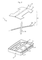
- the extraction mouth 1 of the figure 1 comprises a housing 2 forming a substantially rectangular frame within which extends a trellis 3 having central openings 4 on either side of a central longitudinal crossbar 5.
- the side walls 7 of the housing 2, parallel to the crosspiece 5, have lateral openings 6 communicating the interior and exterior of the case.
- the housing 2 is adapted to be placed on a partition (not shown) facing a light thereof and to allow the circulation of an extraction flow in an extraction direction E represented by an arrow on the figure 1 .
- a membrane 8 comprises a flexible and flexible sheet 9 of hydrophobic synthetic material, for example PET (polyethylene terephthalate) or PVC (polyvinyl chloride).
- the hydrophobic foil 9 comprises a central fastening line 10 of elongated rectangular shape, extending substantially over the entire length of the sheet, adapted to be fixed on the crosspiece 5 of the housing 2 by means not shown such as screws or rivets, and two wings 11 extending on either side of this line 10.
- the membrane 8 also comprises two stiffeners 12 in the form of rectangular strips of hydrophilic synthetic material, for example polyamide and preferably polyamide 6.6. These stiffeners have a width of the order of 10 to 20 mm for a thickness of between 50 microns and 150 microns.
- the length of the stiffeners 12 is substantially equal to the width of the hydrophobic sheet 9.
- the stiffeners 12 are glued to the face of the hydrophobic sheet 9 opposite the housing 2, that is to say on the downstream face in the direction extraction E of the extraction stream.
- the stiffeners 12 are glued so that their main axis 13 is oriented perpendicularly to the line 10 for fixing the hydrophobic sheet 9 and the crosspiece 5.
- Each stiffener 12 is placed symmetrically with respect to a median axis orthogonal to the line Fixing the hydrophobic sheet 9.
- the bonding of the stiffeners 12 on the downstream face of the hydrophobic sheet 9 can be achieved by any means making it possible to make at least the ends of the stiffeners integral with the sheet, so that an elongation of the stiffeners has the effect of modifying the Bending radius of the membrane 8.
- a bonding by interposition of a polyurethane or acrylic adhesive film between the hydrophobic sheet 9 and each stiffener makes it possible to make the hydrophobic sheet integral with the entire length of the stiffener and to make it more homogeneous. the influence of the lengthening of the stiffener on the curvature of the membrane.
- a fixation by points along the main axis 13 of the stiffener may be employed, whether by a succession of points of glue or by a weld between the material of the hydrophobic sheet and that of the stiffener, by laser pulses. for example.
- an extraction mouth is as follows: in the presence of a given pressure difference on either side of the membrane 8, and for a given moisture content of the flow extraction air, it takes a determined curvature, masking more or less the central openings 4.
- the longitudinal edges of the membrane opposite the cross member 5 divide a portion of the flow of exhaust air passing through the openings 6.
- an increase in the pressure difference tends to press the membrane more on the central openings and to reduce the flow through the lateral openings, increasing the pressure drop across the mouth of the body. 'extraction.
- the elasticity of the membrane tends to straighten the wings thereof and to increase the flow of air through the side openings, thus reducing the pressure drop.
- the flow rate is thus regulated as a function of the pressure difference, for a given humidity level.
- FIGS. figures 5 and 6 A variant of this embodiment of the extraction mouth is shown in FIGS. figures 5 and 6 in which the elements having the same function as those of the figure 1 are designated by the same references, even if their shape is different.
- the housing 2 is substantially identical to that of the figure 1 .
- the lateral openings 6 of the figure 1 no longer useful, they have not been shown, but it is possible to use a housing having these openings without disturbing the function of the extraction mouth.
- the housing 2 comprises along each side wall 7, inside the housing, a rim 14 for fixing the membrane.
- the hydrophobic sheet 9 comprises two separate wings 11, each having a line 10 for attachment to a longitudinal edge.
- On the face of each of the two wings 11 opposite the housing 2 are fixed three stiffeners 12 whose main axis is orthogonal to the line 10 of attachment.
- Each wing thus equipped with stiffeners is fixed by its line 10 of attachment to the flange 14 of attachment, thus forming a membrane 8 in two parts, open in its middle, parallel to the crosspiece 5.
- the membrane 8 is thus formed of two half cantilevered membranes.
- this variant of the extraction mouth 1 is similar to that of the figure 1 in the presence of moisture, the elongation of the stiffeners 12 straightens each wing 11, increasing the air passage between the two half-membranes. During an increase in the pressure difference, the two half-membranes are pressed onto the mesh 3, thus masking the central openings 4.
- This variant of the extraction mouth is particularly well adapted to operate with low pressure differences.
- the stiffeners 12 are oriented so that their main axis 13 is orthogonal both to the line 10 for fixing the hydrophobic sheet 9, located in this embodiment on a transverse edge of the sheet, and to the plane of flexion of the leaf.
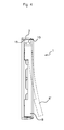
- the hydrophobic sheet 9 is fixed on a flange 15 fixing orthogonal to the cross member 5 and bears thereon.
- the wings 11 thus extend on either side of the crossbar 5 and their bending plane is substantially orthogonal thereto.
- the stiffeners 12 are oriented parallel to the crossbar 5, and fixed symmetrically on either side thereof.
- the diaphragm 8 is plated by its longitudinal central part on the crosspiece 5 and the regulation of the flow rate as a function of the pressure difference is carried out in a similar manner to the extraction mouth of the figure 1 by the elasticity of the wings 11.
- the elongation of the stiffeners 12 causes a warping of the surface of the membrane 8 which deviates from the cross member 5 opposite the rim 15 to take a position 8 'as drawn in dashes on the figure 4 . It is therefore understood that the membrane is then removed from the openings in the housing and that the extraction rate increases with increasing humidity.
- the stiffeners 12 are fixed to the hydrophobic sheet 9 so that their main axis 13 is oblique with respect to the line of attachment of the membrane.
- the stiffeners 12 are formed of two strips of hydrophilic material crossing in their middle.
- the stiffeners 12 may also be derived from a cut of a sheet of cross-shaped hydrophilic material in order to avoid an extra thickness in the crossing zone of the stiffeners.
- the stiffeners are oriented so that their ends are oriented towards the opposite corners of the hydrophobic sheet 9.
- This is fixed by its central fastening line, of elongated rectangular shape, extending substantially over the entire length of the sheet on the crossbar 5 of the housing 2 which is identical to that of the figure 1 .
- the operation of the extraction mouth according to this embodiment of the invention is similar to that of the mouth illustrated in FIG. figure 1 , the membrane 8 having the same behavior in the presence of a pressure difference on either side of the partition on which is fixed the extraction mouth.
- the elongation of the stiffeners 12 has the effect of lifting the corners of the hydrophobic sheet 9, thus increasing the flow rate extraction air.
Landscapes
- Engineering & Computer Science (AREA)
- Physics & Mathematics (AREA)
- Fluid Mechanics (AREA)
- Chemical & Material Sciences (AREA)
- Combustion & Propulsion (AREA)
- Mechanical Engineering (AREA)
- General Engineering & Computer Science (AREA)
- Separation Using Semi-Permeable Membranes (AREA)
- Respiratory Apparatuses And Protective Means (AREA)
Applications Claiming Priority (1)
| Application Number | Priority Date | Filing Date | Title |
|---|---|---|---|
| FR1355491A FR3007109B1 (fr) | 2013-06-13 | 2013-06-13 | Bouche d'extraction de gaz a debit simultanement variable en fonction de l'humidite et de la pression |
Publications (2)
| Publication Number | Publication Date |
|---|---|
| EP2813774A2 true EP2813774A2 (de) | 2014-12-17 |
| EP2813774A3 EP2813774A3 (de) | 2015-11-04 |
Family
ID=49111408
Family Applications (1)
| Application Number | Title | Priority Date | Filing Date |
|---|---|---|---|
| EP14171838.7A Withdrawn EP2813774A3 (de) | 2013-06-13 | 2014-06-10 | Gasextraktionsöffnung mit Durchsatz, der gleichzeitig in Abhängigkeit von der Feuchtigkeit und dem Druck variiert werden kann |
Country Status (2)
| Country | Link |
|---|---|
| EP (1) | EP2813774A3 (de) |
| FR (1) | FR3007109B1 (de) |
Citations (1)
| Publication number | Priority date | Publication date | Assignee | Title |
|---|---|---|---|---|
| FR2729746A1 (fr) | 1995-01-19 | 1996-07-26 | Zaniewski Michel | Perfectionnements aux dispositifs de regulation automatique des debits d'air notamment pour la ventilation des locaux collectifs, et moyens d'intervention manuelle sur ladite regulation |
Family Cites Families (6)
| Publication number | Priority date | Publication date | Assignee | Title |
|---|---|---|---|---|
| FR2589996B2 (fr) * | 1981-06-30 | 1989-05-05 | Serva Soc | Moyens pour la mise en oeuvre d'un procede de regulation de la ventilation d'un local |
| FR2521267B1 (fr) * | 1982-02-05 | 1985-11-22 | Serva Soc | Stabilisateur de debit pour conduit de ventilation |
| FR2620202B1 (fr) * | 1987-03-31 | 1990-03-09 | Zaniewski Michel | Perfectionnements aux dispositifs concourant a la ventilation rationnelle de chacun des locaux d'un meme ensemble |
| FR2805032B1 (fr) * | 2000-02-14 | 2002-06-07 | Michel Zaniewski | Dispositif de regulation automatique du debit d'air pour la ventilation d'un local |
| FR2847661B1 (fr) * | 2002-11-25 | 2005-02-25 | Invent Or | Bouche d'extraction de gaz a membrane flexible de regulation |
| FR2984465B1 (fr) * | 2011-12-16 | 2013-12-20 | Vti | Bouche d'extraction de gaz a reglage automatique et procede de fabrication d'une telle bouche |
-
2013
- 2013-06-13 FR FR1355491A patent/FR3007109B1/fr active Active
-
2014
- 2014-06-10 EP EP14171838.7A patent/EP2813774A3/de not_active Withdrawn
Patent Citations (1)
| Publication number | Priority date | Publication date | Assignee | Title |
|---|---|---|---|---|
| FR2729746A1 (fr) | 1995-01-19 | 1996-07-26 | Zaniewski Michel | Perfectionnements aux dispositifs de regulation automatique des debits d'air notamment pour la ventilation des locaux collectifs, et moyens d'intervention manuelle sur ladite regulation |
Also Published As
| Publication number | Publication date |
|---|---|
| FR3007109B1 (fr) | 2015-06-12 |
| FR3007109A1 (fr) | 2014-12-19 |
| EP2813774A3 (de) | 2015-11-04 |
Similar Documents
| Publication | Publication Date | Title |
|---|---|---|
| EP0771578B1 (de) | Gegendruckregelkartusche für Atemmaske | |
| FR2970009A1 (fr) | Ensemble acoustiquement absorbant | |
| EP2475917A1 (de) | Druckausgleichsventil | |
| FR3028537A1 (fr) | Procede et systeme destines a permettre une isolation installee a posteriori | |
| EP2813774A2 (de) | Gasextraktionsöffnung mit Durchsatz, der gleichzeitig in Abhängigkeit von der Feuchtigkeit und dem Druck variiert werden kann | |
| EP3034150A1 (de) | Nebeltrennvorrichtung aus versetzt angeordneten profileinheiten | |
| EP2604942B1 (de) | Gasextraktionsöffnung mit automatischer Regulierung, und Herstellungsverfahren einer solchen Öffnung | |
| FR2847661A1 (fr) | Bouche d'extraction de gaz a membrane flexible de regulation | |
| FR3067096B1 (fr) | Entree d'air pour menuiserie et ventilation mecanique controlee comprenant une telle entree d'air | |
| FR3060633A1 (fr) | Dispositif de diffusion d'air pour coffre, notamment pour de volet roulant, pour coffre de brise soleil ou pour coffre de store banne | |
| FR2974404A1 (fr) | Systeme de ventilation | |
| FR2886110A1 (fr) | Dispositif ornemental pour oreille. | |
| FR2805032A1 (fr) | Dispositif de regulation automatique du debit d'air pour la ventilation d'un local | |
| FR3095031A1 (fr) | Bouche d’extraction d’air | |
| FR2713318A1 (fr) | Entrée d'air autoréglable, antiretour, acoustique à rouleau; installation comprenant une telle entrée d'air. | |
| FR2554903A1 (fr) | Vanne automatique a section variable pour un ecoulement gazeux | |
| FR2770894A1 (fr) | Dispositif de filtration destine notamment a epurer l'air entrant dans un local ou similaire | |
| EP2028428B1 (de) | Selbstregulierende Belüftungsöffnung mit gedämpftem Absperrschieber | |
| FR3162834A1 (fr) | Bouche d'extraction d'air ajustable pour la ventilation d'une pièce, équipée d'un système de montage démontable | |
| WO2010115975A1 (fr) | Cheminee d'entree d'air pour un systeme d'aeration | |
| FR2861795A1 (fr) | Amenagement des coulisses d'un volet roulant pour l'accrochage lateral de son tablier et crochets de lame associes | |
| FR3067097A1 (fr) | Entree d'air murale et ventilation mecanique controlee comprenant une telle entree d'air | |
| EP0899518A1 (de) | Belüftungssystem für Viehställe | |
| FR2725769A1 (fr) | Regulateur de debit perfectionne, notamment pour installation de ventilation ou de climatisation | |
| FR2827664A1 (fr) | Regulateur de debit pour installation de ventilation |
Legal Events
| Date | Code | Title | Description |
|---|---|---|---|
| 17P | Request for examination filed |
Effective date: 20140610 |
|
| AK | Designated contracting states |
Kind code of ref document: A2 Designated state(s): AL AT BE BG CH CY CZ DE DK EE ES FI FR GB GR HR HU IE IS IT LI LT LU LV MC MK MT NL NO PL PT RO RS SE SI SK SM TR |
|
| AX | Request for extension of the european patent |
Extension state: BA ME |
|
| PUAI | Public reference made under article 153(3) epc to a published international application that has entered the european phase |
Free format text: ORIGINAL CODE: 0009012 |
|
| PUAL | Search report despatched |
Free format text: ORIGINAL CODE: 0009013 |
|
| AK | Designated contracting states |
Kind code of ref document: A3 Designated state(s): AL AT BE BG CH CY CZ DE DK EE ES FI FR GB GR HR HU IE IS IT LI LT LU LV MC MK MT NL NO PL PT RO RS SE SI SK SM TR |
|
| AX | Request for extension of the european patent |
Extension state: BA ME |
|
| RIC1 | Information provided on ipc code assigned before grant |
Ipc: F24F 11/00 20060101AFI20150925BHEP Ipc: F24F 11/047 20060101ALI20150925BHEP |
|
| R17P | Request for examination filed (corrected) |
Effective date: 20160502 |
|
| RBV | Designated contracting states (corrected) |
Designated state(s): AL AT BE BG CH CY CZ DE DK EE ES FI FR GB GR HR HU IE IS IT LI LT LU LV MC MK MT NL NO PL PT RO RS SE SI SK SM TR |
|
| STAA | Information on the status of an ep patent application or granted ep patent |
Free format text: STATUS: THE APPLICATION IS DEEMED TO BE WITHDRAWN |
|
| 18D | Application deemed to be withdrawn |
Effective date: 20190103 |