EP2813864A2 - Empfänger und Verfahren zur multimodalen Navigation - Google Patents
Empfänger und Verfahren zur multimodalen Navigation Download PDFInfo
- Publication number
- EP2813864A2 EP2813864A2 EP14166288.2A EP14166288A EP2813864A2 EP 2813864 A2 EP2813864 A2 EP 2813864A2 EP 14166288 A EP14166288 A EP 14166288A EP 2813864 A2 EP2813864 A2 EP 2813864A2
- Authority
- EP
- European Patent Office
- Prior art keywords
- receiver
- satellite
- satellites
- positioning
- information
- Prior art date
- Legal status (The legal status is an assumption and is not a legal conclusion. Google has not performed a legal analysis and makes no representation as to the accuracy of the status listed.)
- Withdrawn
Links
- 238000000034 method Methods 0.000 title claims description 50
- 238000004364 calculation method Methods 0.000 claims abstract description 81
- 239000011159 matrix material Substances 0.000 claims description 28
- 238000006073 displacement reaction Methods 0.000 claims description 26
- 238000012545 processing Methods 0.000 claims description 12
- 238000001914 filtration Methods 0.000 claims description 8
- 238000011156 evaluation Methods 0.000 claims description 5
- 238000001514 detection method Methods 0.000 description 11
- 238000005259 measurement Methods 0.000 description 11
- 238000003860 storage Methods 0.000 description 9
- 238000005516 engineering process Methods 0.000 description 7
- 230000003287 optical effect Effects 0.000 description 5
- 238000010586 diagram Methods 0.000 description 4
- 230000015654 memory Effects 0.000 description 4
- 230000005540 biological transmission Effects 0.000 description 3
- 238000012986 modification Methods 0.000 description 3
- 230000004048 modification Effects 0.000 description 3
- 238000006243 chemical reaction Methods 0.000 description 2
- 238000004891 communication Methods 0.000 description 2
- 230000003247 decreasing effect Effects 0.000 description 2
- 238000012544 monitoring process Methods 0.000 description 2
- RYGMFSIKBFXOCR-UHFFFAOYSA-N Copper Chemical compound [Cu] RYGMFSIKBFXOCR-UHFFFAOYSA-N 0.000 description 1
- 238000007792 addition Methods 0.000 description 1
- 238000013461 design Methods 0.000 description 1
- 230000009977 dual effect Effects 0.000 description 1
- 230000000694 effects Effects 0.000 description 1
- -1 elements Substances 0.000 description 1
- 239000000835 fiber Substances 0.000 description 1
- 238000004519 manufacturing process Methods 0.000 description 1
- 239000000463 material Substances 0.000 description 1
- 238000005457 optimization Methods 0.000 description 1
- 239000004065 semiconductor Substances 0.000 description 1
- 238000006467 substitution reaction Methods 0.000 description 1
Images




Classifications
-
- G—PHYSICS
- G01—MEASURING; TESTING
- G01S—RADIO DIRECTION-FINDING; RADIO NAVIGATION; DETERMINING DISTANCE OR VELOCITY BY USE OF RADIO WAVES; LOCATING OR PRESENCE-DETECTING BY USE OF THE REFLECTION OR RERADIATION OF RADIO WAVES; ANALOGOUS ARRANGEMENTS USING OTHER WAVES
- G01S19/00—Satellite radio beacon positioning systems; Determining position, velocity or attitude using signals transmitted by such systems
- G01S19/38—Determining a navigation solution using signals transmitted by a satellite radio beacon positioning system
- G01S19/39—Determining a navigation solution using signals transmitted by a satellite radio beacon positioning system the satellite radio beacon positioning system transmitting time-stamped messages, e.g. GPS [Global Positioning System], GLONASS [Global Orbiting Navigation Satellite System] or GALILEO
- G01S19/42—Determining position
- G01S19/421—Determining position by combining or switching between position solutions or signals derived from different satellite radio beacon positioning systems; by combining or switching between position solutions or signals derived from different modes of operation in a single system
- G01S19/425—Determining position by combining or switching between position solutions or signals derived from different satellite radio beacon positioning systems; by combining or switching between position solutions or signals derived from different modes of operation in a single system by combining or switching between signals derived from different satellite radio beacon positioning systems
-
- G—PHYSICS
- G01—MEASURING; TESTING
- G01S—RADIO DIRECTION-FINDING; RADIO NAVIGATION; DETERMINING DISTANCE OR VELOCITY BY USE OF RADIO WAVES; LOCATING OR PRESENCE-DETECTING BY USE OF THE REFLECTION OR RERADIATION OF RADIO WAVES; ANALOGOUS ARRANGEMENTS USING OTHER WAVES
- G01S19/00—Satellite radio beacon positioning systems; Determining position, velocity or attitude using signals transmitted by such systems
- G01S19/01—Satellite radio beacon positioning systems transmitting time-stamped messages, e.g. GPS [Global Positioning System], GLONASS [Global Orbiting Navigation Satellite System] or GALILEO
- G01S19/13—Receivers
- G01S19/33—Multimode operation in different systems which transmit time stamped messages, e.g. GPS/GLONASS
-
- G—PHYSICS
- G01—MEASURING; TESTING
- G01S—RADIO DIRECTION-FINDING; RADIO NAVIGATION; DETERMINING DISTANCE OR VELOCITY BY USE OF RADIO WAVES; LOCATING OR PRESENCE-DETECTING BY USE OF THE REFLECTION OR RERADIATION OF RADIO WAVES; ANALOGOUS ARRANGEMENTS USING OTHER WAVES
- G01S19/00—Satellite radio beacon positioning systems; Determining position, velocity or attitude using signals transmitted by such systems
- G01S19/38—Determining a navigation solution using signals transmitted by a satellite radio beacon positioning system
- G01S19/39—Determining a navigation solution using signals transmitted by a satellite radio beacon positioning system the satellite radio beacon positioning system transmitting time-stamped messages, e.g. GPS [Global Positioning System], GLONASS [Global Orbiting Navigation Satellite System] or GALILEO
- G01S19/52—Determining velocity
Definitions
- BeiDou Compass
- GPS Global Positioning System
- GLONASS Global Navigation Satellite System
- Galileo satellite navigation system developed by China, United States, Russia, and Europe, respectively.
- the BeiDou satellite navigation system is self-developed by China and can work independently from other satellite navigation systems.
- a receiver can only receive satellite signals from one single satellite navigation system to perform positioning or navigation.
- such conventional receiver has a relatively low positioning accuracy.
- the present disclosure describes a receiver for a multi-mode navigation system.
- the receiver includes a base band unit and a calculation unit.
- the base band unit is configured for allocating resources to positioning satellites in each of one or more navigation systems, and capturing and tracking the positioning satellites with the allocated resources to obtain satellite information of each of the positioning satellites, wherein the satellite information includes one or more of pseudo-ranges, position coordinates, velocity information, and frequency information of the positioning satellites.
- the calculation unit is configured for receiving the satellite information from the base band unit, evaluating the positioning satellites in each navigation system, and determining a positioning parameter of the receiver. Determination of the positioning parameter includes calculating a position and a velocity of the receiver based on the satellite information according to a least square algorithm.
- the present disclosure describes a method for navigation, the method includes: receiving and processing satellite navigation signals from at least one navigation system; allocating resources for detected positioning satellites; capturing and tracking the positioning satellites with allocated resources to obtain satellite information, wherein the satellite information includes one or more of pseudo-ranges, position coordinates, velocity information, and frequency information of the positioning satellites; evaluating the positioning satellites according to the satellite information; and determining a positioning parameter of the receiver. Determining the positioning parameter of the receiver includes calculating a position and a velocity of the receiver based on a least square algorithm.
- determining the positioning parameter of the receiver may comprise calculating a position and a velocity of the receiver based on a least square algorithm.
- the calculation unit may determine whether an estimated value X1 of the state vector X based on the least square algorithm converges to an allowable range, wherein if the estimated value X1 doesn't converge to the allowable range, the calculation unit may update the value of state vector X with a prior estimated value X1, and may estimate the value of the state vector X again, and wherein if the estimated value X1 converges to the allowable range, the calculation unit may obtain the positioning parameter of the receiver according to the estimated value X1.
- the calculation unit may determine whether an estimated value X1 of the state vector X based on the weighted least square algorithm converges to an allowable range, wherein if the estimated value X1 doesn't converge to the allowable range, the calculation unit may update the value of state vector X with a prior estimated value X1, and may estimate the value of the state vector X again, and wherein if the estimated value X1 converges to the allowable range, the calculation unit may obtain the position information of the receiver according to the estimated value X1.
- calculating the velocity of the receiver may further comprise:
- d ij v ij_x a ij_x + v ij_y a ij_y + v ij_z a ij_z
- T represents a number of satellites used for calculating the velocity
- i represents i th satellite navigation system
- j represents j th positioning satellite in the i th satellite navigation system
- c velocity of
- the navigation systems in present teaching may include the Beidou (Compass) satellite navigation system, the Global Positioning System (GPS), the GLONASS satellite navigation system, the Galileo satellite navigation system, and/or any other satellite navigation systems presently available or developed in the future.
- Each satellite navigation system may include one or more satellites.
- Beidou satellite navigation system includes 9 Beidou satellites, and will include 30 available satellites by 2020.
- the satellites transmitting signals which can be received by a receiver are referred to as positioning satellites.
- the signals sent from the positioning satellites may be called satellite signals.
- the receiver can receive Beidou satellite signals from 6 Beidou satellites, these 6 Beidou satellites are called Beidou positioning satellites.
- FIG. 1 illustrates a block diagram of a receiver 100, in accordance with one embodiment of the present teaching.
- receiver 100 includes a detection module 10 and a calculation module 20.
- Detection module 10 may be configured for detecting and/or receiving one or more signals directed to navigation and determining one or more satellite navigation systems from where the one or more signals are sent.
- the one or more signals may be satellite signals sent from satellites in the one or more satellite navigation systems.
- Detection module 10 may detect if the received satellite signals are sent from one or more satellite navigation systems. For example, detection module 10 may detect the Beidou satellite signals, the GPS satellite signals and the Galileo satellite signals according to an I-branch ordinary ranging code of the received satellite signals and may detect the GLONASS satellite signals according to a frequency of the received satellite signals.
- Calculation module 20 may be coupled to detection module 10 and configured for obtaining or calculating navigation information at receiver 100, based on the one or more signals. The navigation information may be associated with the determined one or more navigation systems. Calculation module 20 may be further configured for calculating a displacement of receiver 100 corresponding to a clock bias between receiver 100 and a satellite navigation system, based on the received satellite signals. For example, calculation module 20 can calculate each displacement of receiver 100 corresponding to each clock bias between receiver 100 and each satellite navigation system, based on the received satellite signals. Calculation module 20, in this example, includes a allocation unit 21, a capturing and tracking unit 22, and a calculation unit 23.
- Allocation unit 21 may be configured for allocating recourses for the positioning satellites in each detected satellite navigation system.
- Capturing and tracking unit 22 may be configured for capturing and tracking the positioning satellites with resources allocated by allocation unit 21 to obtain satellite information from the positioning satellites.
- the satellite information provided by the satellites may include one or more of pseudo range, position coordinates, velocity information and/or frequency information of the corresponding positioning satellites.
- Calculation unit 23 may be configured for calculating the navigation information of the receiver, and each displacement of receiver 100 corresponding to each clock bias between receiver 100 and each of the satellite navigation systems.
- the Calculation module 20 can further include an identification unit (not shown in FIG. 1 ).
- the identification unit may be configured for identifying redundant positioning satellites in each satellite navigation system according to the received satellite information. For example, the identification unit can identify the positioning satellites that provide the satellite information (e.g., pseudo range and Doppler measurement) with many errors as redundant satellites. The satellite signals from the identified redundant satellites may be abandoned and not used for calculating the position of the receiver.
- the identification unit may identify the redundant satellites according to a method of Receiver Autonomous Integrity Monitoring (RAIM).
- RAIM Receiver Autonomous Integrity Monitoring
- the identification unit can also identify the redundant satellites according to the output parameters of each receiver loop, e.g., the variation of the carrier frequency, the variation of the pseudo range measurement, and the like, and/or any combination thereof.
- FIG. 2 illustrates a method for navigation, in accordance with one embodiment of the present teaching.
- FIG. 2 may be described in combination with FIG. 1 .
- specific processes are disclosed in FIG. 2 , such processes are examples. That is, the present teaching is well suited to perform variations of the processes recited in FIG. 2 .
- detection module 10 in receiver 100 may receive one or more signals directed to navigation.
- one or more navigation systems may be determined.
- the one or more signals may be sent from the one or more navigation systems.
- the one or more navigation systems may be different satellite navigation systems.
- navigation information may be obtained based on the one or more signals.
- the navigation information may be associated with the determined one or more navigation systems.
- Calculation module 20 in receiver 100 may calculate the navigation information.
- Calculation module 20 may also calculate each displacement of receiver 100 corresponding to each clock bias between receiver 100 and each satellite navigation system according to the satellite information received from the detected satellite navigation systems, when the satellite signals are received from more than one satellite navigation systems.
- the satellite information provided by the positioning satellites can include, but is not limited to, one or more of pseudo-range, position coordinates, frequency information, Doppler information, ephemeris information, velocity information of the positioning satellites, and the like, and/or any combination therefor.
- the navigation information of the receiver 100 may include the position coordinate information of the receiver 100 and the velocity information of the receiver 100.
- the Beidou satellite signals, the GPS satellite signals and Galileo satellite signals are based on Code Division Multiple Access (CDMA) technology
- the GLONASS satellite signals are based on Frequency Division Multiple Access (FDMA) technology.
- receiver 100 at S10 can detect if the received satellite signals are from one or more satellite signals.
- Receiver 100 may distinguish the GPS satellite signals, the Beidou satellite signals, and the Gallileo satellite signals from the received satellite signals by using I-branch ordinary ranging code, and distinguish the GLONASS satellite signals from the received satellite signals according to frequency.
- the above-mentioned parameters can be all known to the corresponding satellite.
- the parameters can be obtained at receiver 100 by capturing and tracking the satellite signals.
- the value of f in each satellite navigation system may be different. Because the Beidou satellite signals, the GPS satellite signals and the Galileo satellite signals are be based on CDMA technology, the transmitting frequencies of the three satellite navigation systems in the same signal segment may be the same. Since the GLONASS satellite signals is based on FDMA technology, the GLONASS satellite signals can be distinguished according to frequency.
- a pseudo-random number (PRN) of each Beidou satellite, GPS satellite, and Galileo satellite may be unique. Therefore, a type of satellite can be determined based on the pseudo-random number sequence, i.e., the parameter C in equation (1).
- the available satellite signals can be captured and identified by reestablishing the pseudo-random number sequence of the satellites.
- the method for establishing the PRN sequence can be obtained from an Interface Control Document (ICD) of each satellite navigation system. Therefore, receiver 100 may search for possible receiving frequency of the satellite signal and the PRN information. After receiving a satellite signal from a satellite, receiver 100 can obtain the navigation message data D in the I-branch and the initial carrier phase ⁇ of the satellite signal. A baseband channel may establish a PRN sequence in accordance with the PRN sequence of the satellite. Receiver 100 may capture and track the satellite. If the satellite is captured and tracked successfully, the present satellite signal can be included in the input signals. In addition, when the established PRN sequence is in accordance with the PRN sequence of the captured and tracked satellite signals, a correlation peak appears with respect to the CDMA signals.
- ICD Interface Control Document
- receiver 100 can detect if the satellite is captured successfully or not by detecting a correlation peak of the CDMA signals based on a capturing threshold.
- the satellite can broadcast two kinds of ranging code, which are loaded on the I-branch and Q-branch of the satellite signals, respectively.
- the I-branch of the satellite signals is the civilian ordinary ranging code
- the Q-branch of the satellite signals is professional accurate ranging code (for example, for military use)
- receiver 100 can only receive the Q-branch after being authorized.
- a detailed method for calculating position information of receiver 100 will be described below in combination with FIG. 3 .
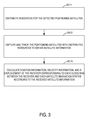
- FIG. 3 illustrates a process for navigation based on multiple satellite navigation systems, in accordance with one embodiment of the present teaching.
- FIG. 3 is described in combination with FIG. 1 and FIG. 2 .
- the process in FIG. 3 may be included in S30 in FIG. 2 .
- Receiver 100 can allocate resources for the positioning satellites of the detected satellite navigation systems. For example, receiver 100 may allocate resources for the positioning satellites based on visibility, performance and an environment of the positioning satellites, at S171.
- the allocated resources may include, for example, capturing channel and tracking channel which are hardware resources, and CPU system resources which are software resources, etc.
- the visibility of the satellite can be determined based on the positioning satellite ephemeris received by receiver 100.
- receiver 100 may detect if the positioning satellite is within the sight of receiver 100 or not. If the positioning satellite is within the sight of receiver 100, receiver 100 can allocate resources for the positioning satellite; otherwise, receiver 100 may not allocate resources or may reduce allocated resources for the positioning satellite.
- the coded formats of the satellite signals may be different.
- the scanning time for the satellite signals with different formats may not be the same. If the scanning time is too long, the positioning efficiency may be decreased. Therefore, the scanning time may also be considered by receiver 100 when the resources are allocated.
- Receiver 100 may capture and track the positioning satellites with allocated resources to obtain satellite information such as, for example, pseudo-range, position coordinate, velocity information and frequency information of each positioning satellite, and the like, and/or any combination thereof, from the positioning satellites, at S172.
- the measured pseudo-range of the positioning satellite may have an error.
- the number of the positioning satellites can be increased when the error is unacceptable, to weaken the effect of measurement errors caused by other satellites on the positioning result. Thus, the positioning accuracy can be improved.
- the number of the positioning satellites may be 12.
- the number of positioning satellites in various embodiments may be more or less.
- receiver 100 may calculate the position information, the velocity information of receiver 100, and each displacement of receiver 100 corresponding to each clock bias between receiver 100 and each satellite navigation system according to the satellite information received at S172.
- ⁇ 11 ⁇ 1m represent the pseudo-ranges of the m positioning satellites from a first satellite navigation system, respectively; respectively; ⁇ k1 ⁇ kp represent the pseudo-ranges of p positioning satellites from a k th satellite navigation system, respectively.
- ⁇ 21 ⁇ 2n represent the pseudo-ranges of n positioning satellites from a second satellite navigation system.
- the pseudo-ranges of the positioning satellites can be measured by a tracking loop of receiver 100.
- (x 1i , y 1i , z 1i ) represents a position coordinate of i th positioning satellite from the first satellite navigation system, wherein 1 ⁇ i ⁇ m;
- (x 2j , y 2j , z 2j ) represents a position coordinate of j th positioning satellite from the second satellite navigation system, wherein 1 ⁇ j ⁇ n;
- (x ko , y ko , z ko ) represents a position coordinate of o th positioning satellite from the kth satellite navigation system, wherein 1 ⁇ o ⁇ p.
- receiver 100 allocates resources to 12 positioning satellites, 1 ⁇ m+n+p ⁇ 12.
- the position coordinate of each positioning satellite can be calculated according to the orbit parameters and positioning time of the corresponding positioning satellite.
- b u1 represents a displacement of receiver 100 corresponding to a clock bias between receiver 100 and the first satellite navigation system, i.e., the displacement corresponding to the clock bias between the local clock of receiver 100 and the clock of the first satellite navigation system
- b u2 represents a displacement of receiver 100 corresponding to a clock bias between receiver 100 and the second satellite navigation system
- b uk represents a displacement of receiver 100 corresponding to a clock bias between receiver 100 and the k th satellite navigation system
- (x u , y u , z u ) represents a position coordinate of receiver 100.
- the equations (2-11)-(2-2n) can be used to calculate the position information of receiver 100.
- there are five unknowns, i.e., x u , y u , z u , b u1 and b u2 so that at least five positioning satellites are be needed to perform the positioning calculation.
- the first situation may include calculating an additional displacement of receiver 100 corresponding to a clock bias between receiver 100 and the additional satellite navigation system to correct the calculated navigation information.
- the positioning accuracy may be improved in the first situation, compared to the second situation.
- each displacement of receiver 100 corresponding to each clock bias between receiver 100 and each satellite navigation system may be utilized to calculate the position information of receiver 100.
- the received satellite information can be from one of the above-mentioned satellite navigation system or a combination thereof.
- ⁇ ij x ij - x u 2 + y ij - y u 2 + z ij - z u 2 + b ui ;
- ⁇ ij represents a pseudo-range of the j th positioning satellite in the i th satellite navigation system
- b ui represents a displacement of receiver 100 corresponding to a clock bias between receiver 100 and the i th satellite navigation system, i.e., the displacement corresponding to the clock bias between the local clock of receiver 100 and the clock of the i th satellite navigation system
- (x ij , y ij , z ij ) represents a position coordinate of the j th positioning satellite in the i th satellite navigation system
- (x u , y u , z u ) represents a position coordinate of receiver 100.
- the number of the available positioning satellites in the satellite navigation system may be relatively low.
- the positioning accuracy may be decreased if using satellite information from such a satellite navigation system with relatively few available positioning satellites. If receiver 100 can receive satellite signals from multiple satellite navigation systems, the number of the available positioning satellites can be increased. Thus, the positioning accuracy and velocity measurement accuracy can both be significantly improved.
- the transmitting frequencies of the satellite signals from the same satellite navigation system may be the same.
- the transmitting frequency of the satellite signals L1 from the GPS satellite can be 1.57542e9Hz.
- the receiving frequency and the transmitting frequency may be included in the frequency information.
- (v ij_x , v ij_y , v ij_z ) represents a velocity vector of the j th positioning satellite in the i th satellite navigation system and can be calculated according to the positioning satellite ephemeris and a present time;
- (a ij_x , a ij_y , a ij_z ) represents a direction vector of the j th positioning satellite in the i th satellite navigation system relative to receiver 100, and
- a ij_x (x ij -x u )/r,
- a ij_y (y ij -y u )/r,
- a ij_z (z ij -z u )/r, wherein r represents a distance from receiver 100 to the jth positioning satellite in the i th satellite navigation system;
- receiver 100 can generate a navigation path for navigation.
- the accuracy of the positioning calculation can be increased by increasing the number of the positioning satellites. If the tracking quality of the satellites is poor because of, for example, measurement errors in the satellite pseudo-ranges and Doppler measurements in the satellite information provided by the satellites, the positioning accuracy may, in fact, decrease when the number of the positioning satellites is increased. Therefore, it may be necessary to identify the positioning satellites which provide the satellite information (e.g., pseudo range and Doppler measurement) with many errors.
- the identification unit in calculation module 20 of receiver 100 may identify the redundant positioning satellites in each satellite navigation system according to the received satellite information.
- the satellite signals from the identified redundant satellites may be abandoned and may not be used to calculate the position of receiver 100.
- the identification unit can identify the positioning satellites that provide the satellite information (e.g., pseudo range and Doppler measurement) with many errors as the redundant satellites.
- the redundant satellites can be identified according to a method of Receiver Autonomous Integrity Monitoring (RAIM).
- RAIM Receiver Autonomous Integrity Monitoring
- the identification unit can also identify the redundant satellites according to output parameters of each receiver loop, e.g., the variation of the carrier frequency, the variation of the pseudo range measurement, etc.
- FIG. 4 illustrates an exemplary method for navigation, in accordance with one embodiment of the present teaching. Taking an example of BeiDou (Compass) satellite navigation system and Global Positioning System (GPS), FIG. 4 is described in combination with FIG. 1 .
- BeiDou Compass
- GPS Global Positioning System
- Detection module 10 in receiver 100 may receive the GPS satellite signals, at S11. If receiver 100 receives the GPS satellite signals, detection module 10 may further detect if receiver 100 receives the Beidou satellite signals, at S12. Otherwise, if receiver 100 does not receive the GPS satellite signals, detection module 10 in receiver 100 may still detect if the Beidou satellite signals are received, at S13. If no satellite signals are received from either GPS system or BeiDou system, at S14, no position may be performed and the detection module 10 may continue detecting satellite signals, i.e., moving back to S11 again.
- receiver 100 can distinguish the GPS satellite signals and the Beidou satellites from the received satellite signals by using I-branch ordinary ranging code at S11, S12, and S13, respectively.
- receiver 100 can perform positioning in a single mode based on the GPS satellite signals, at S15. If receiver 100 does not receive the GPS satellite signals, but receives the Beidou satellite signals, receiver 100 may perform positioning in a single mode based on the Beidou satellite signals, at S16.
- the (x i , y i , z i ) can be calculated according to the orbit parameters and the positioning time of the i th Beidou positioning satellite.
- the orbit parameters can be obtained by demodulating navigation message data D on the I-branch and analyzing and collecting the ICD document of the satellite navigation system after the satellite signals are tracked and locked.
- the coordinate (x i , y i , z i ) may be Earth-centered Earth-fixed (ECEF) coordinate. In the Earth-centered Earth-fixed (ECEF) coordinate system, the Earth's center represents the origin point of the coordinate.
- Z axis points to Northward along the Earth's rotation axis direction;
- X axis points to the latitude and longitude position (0, 0); and
- Y axis points to 90 degree longitude, wherein the X axis, Y axis and Z axis consist of a right-handed coordinate system.
- b u represents a displacement of receiver 100 corresponding to the clock bias between receiver 100 and the Beidou satellite navigation system;
- (x u , y u , z u ) represents a position coordinate of receiver 100.
- Equations (5-1)-(5-m) There are four unknowns in equations (5-1)-(5-m), i.e., x u , y u , z u and b u .
- the four unknowns can be calculated according to the satellite information from at least four Beidou positioning satellites.
- receiver 100 can perform positioning in a dual mode, at S17, i.e., receiver 100 can perform positioning according to the GPS satellite signals and the Beidou satellite signals simultaneously at S17.
- Receiver 100 can calculate the position information according to the equations (2-11)-(2-2n). In such a situation, there are five unknowns, i.e., x u , y u , z u , b u1 and b u2 , so that at least five positioning satellites may be needed to perform the positioning calculation.
- detection module 10 can further detect if the received satellite signals are Galileo satellite signals, GLONASS satellite signals, or any other satellite navigation system available presently or in the future. It is also to be understood that the order for detecting the satellite signals from different satellite navigation systems can be randomly selected and may not be limited to the disclosed order in the above example.
- FIG.5 is a block diagram of a multi-mode navigation system for multiple navigation systems, in accordance with one embodiment of the present teaching.
- FIG. 5 may be described in combination with FIG. 4 .
- the multi-mode navigation system is for multiple satellite navigation systems, e.g., a satellite navigation system 501, a satellite navigation system 502, a satellite navigation system 503, and a satellite navigation system 504, and includes a receiver 510 and a client terminal 512.
- Satellite navigation systems 501, 502, 503, and 504 may be respectively corresponding to Beidou satellite system, GPS satellite system, GLONASS satellite system and Galileo satellite system. It is to be noted that the satellite navigation systems can be other satellite navigation systems, and not limited to above-mentioned satellite navigation systems.
- receiver 510 further includes an antenna 505, a Radio Frequency signal processing unit 506, a base band unit 514, and a calculation unit 511.
- antenna 505 is configured to receive at least one satellite navigation signals.
- antenna 505 receives at least one satellite navigation signal from at least one of the Beidou satellite system, GPS satellite system, GLONASS satellite system and Galileo satellite system.
- Radio Frequency signal processing unit 506 processes the satellite navigation signals received by antenna 505 and generates an intermediate-frequency signal accordingly.
- the satellite navigation signals received by antenna 505 are analog signals with high frequency, thus Radio Frequency signal processing unit 506 processes these high frequency signals with some steps, such as filtering, frequency processing (i.e., frequency shifting), analog-to-digital conversion and so on, and generates intermediate-frequency signals correspondingly which can be handled by base band unit 514. Then Radio Frequency signal processing unit 506 transfers these intermediate-frequency signals to base band unit 514.
- Base band unit 514 further includes a capturing unit 507, a tracking unit 508, and a decoder 509.
- base band unit 514 receives the intermediate-frequency signals indicating the received satellite navigation signals, and allocates resources for the positioning satellites from which the satellite navigation signals are transmitted based on visibility, performance, and an environment of the positioning satellites.
- the allocated resources may include capturing channel and tracking channel which are hardware resources, and CPU system resources which are software resources, etc.
- Capturing unit 507 and tracking unit 508 capture and track the positioning satellites which are allocated with resources, and generate navigation messages corresponding to these positioning satellites according to the captured and tracked intermediate-frequency signals.
- Decoder 509 receives the navigation messages and demodulates the navigation messages to obtain the satellite information, i.e., the pseudo-range, position coordinate information, and frequency information, etc.
- the receivers are designed with different antennas, Radio Frequency signal processing units and base band units to support correspondingly different navigation systems.
- the receivers have different hardware structures on antennas, Radio Frequency signal processing units, and base band units to support different satellite navigation systems, i.e., the Beidou satellite system and the GPS satellite system.
- the receivers have the same hardware structures, but execute different software for processing different satellite navigation signals to support different satellite navigation system, i.e., the GLONASS system and GALILEO system.
- Calculation unit 511 receives the satellite signals including the satellite information, e.g., the pseudo-range, position coordinate information, velocity information, and frequency information, and the like, and/or any combination thereof, and calculates the position information and velocity information of receiver 510. In one embodiment, calculation unit 511 evaluates the received satellite signals and determines an optimal combination, i.e., selecting navigation systems and satellites among these navigation systems, for calculating the position and velocity. Evaluation of the received satellite signals includes sorting and filtering of the received satellite signals.
- the satellite information e.g., the pseudo-range, position coordinate information, velocity information, and frequency information, and the like, and/or any combination thereof.
- calculation unit 511 evaluates the received satellite signals and determines an optimal combination, i.e., selecting navigation systems and satellites among these navigation systems, for calculating the position and velocity. Evaluation of the received satellite signals includes sorting and filtering of the received satellite signals.
- Calculation unit 511 calculates the position information and velocity information of receiver 510 and converts the information into the information with a standard format of National Marine Electronics Association (NMEA) code.
- NMEA National Marine Electronics Association
- the NMEA information is further output to client terminal 512, thus, the user can obtain and use the position information and velocity information of receiver 510.
- the position information of receiver 510 can be calculated according to equation (3) and the velocity information of the receiver can be calculated according to equation (4).
- the equations (3) and (4) can be solved by a Least Squares (LS) algorithm.
- Least-squares algorithm is a simple way to achieve true value of some unknown.
- Many optimization problems can be expressed in the form of least squares by minimizing energy or maximizing entropy.
- each satellite navigation system has a clock bias with the receiver.
- Each clock bias corresponds to a different displacement. If the initial value of the receiver's coordinate and the displacement is(x u0 , y u0 , z u0 , b u1 0 , b u2 0 ,..., b uM 0 ), wherein M represents the number of positioning satellites.
- the formula (7) is the observation equation for calculating the position of the receiver based on LS algorithm.
- ⁇ represents a bias between the measured pseudo range and the estimated pseudo range
- ⁇ x includes a bias between the position and the initial position of the receiver and biases between the displacement and the initial displacement
- v represents the noise vector of the observation vector
- H is a ( (N 1 +N 2 +...+N M ) *(3+M)) matrix
- N i represents the number of positioning satellites in i th navigation system.
- the noise vector is a (N 1 +N 2 +...+N M ) *1 matrix, and each element in this matrix is corresponding to the noise of the observation value in observation vector Z.
- ECEF earth-centered earth-fixed
- (x ⁇ u , ⁇ u , ⁇ u ) is equal to an initial coordinate ( x u0 ,y u0 ,z u0 ).
- (x ⁇ u , ⁇ u , ⁇ u ) is equal to the coordinate of the receiver calculated from the last iterative computation.
- the estimated value of the state vector X can be obtained based on the LS algorithm/weighted least squares (WLS) algorithm according to the equation (6-2)/ 6-3), and the position information of the receiver can be obtained.
- WLS weighted least squares
- This computing model is also applicable to the multi-mode navigation system based on the LS algorithm, WLS algorithm and Recursive least squares (RLS) algorithm.
- the state vector X includes the bias between the receiver's position and the initial position of the receiver, thus the position of the receiver can be obtained according to the state vector and the initial position of the receiver.
- the above-mentioned position calculation based on LS algorithm is suitable for position calculation based on M satellite navigation systems, M ⁇ 1.
- M M satellite navigation systems
- ⁇ xj (x ⁇ u - x j )/r ⁇ j
- ⁇ yj ( ⁇ u - y j )/r ⁇ j
- ⁇ zj ( ⁇ u - y j )/r ⁇ j
- x ⁇ u , ⁇ u , ⁇ u represent the initial coordinate of the receiver in earth-centered earth-fixed (ECEF) coordinate system
- r ⁇ j represents an estimated distance from the jth positioning satellite to the receiver.
- the estimated value of the state vector X can be obtained based on the LS algorithm/weighted least squares (WLS) algorithm according to the equation (6-2)/(6-3), and the position information of the receiver can be obtained.
- WLS weighted least squares
- the H is a (N 1 +N 2 )* 5 matrix as shown below.
- H ⁇ 1 ⁇ x ⁇ 1 ⁇ 1 ⁇ y ⁇ 1 ⁇ 1 ⁇ z ⁇ 1 1 0 ⁇ 1 ⁇ x ⁇ 2 ⁇ 1 ⁇ y ⁇ 2 ⁇ 1 ⁇ z ⁇ 2 1 0 ⁇ ⁇ ⁇ ⁇ ⁇ ⁇ ⁇ 1 ⁇ xN 1 ⁇ 1 ⁇ yN 1 ⁇ 1 ⁇ 1 ⁇ zN 1 1 0 ⁇ 2 ⁇ x ⁇ 1 ⁇ 2 ⁇ y ⁇ 1 ⁇ 2 ⁇ zN 1 1 0 ⁇ 2 ⁇ x ⁇ 1 ⁇ 2 ⁇ y ⁇ 1 ⁇ 2 ⁇ z ⁇ 1 0 1 ⁇ 2 ⁇ x ⁇ 2 ⁇ 2 ⁇ y ⁇ 2 ⁇ 2 ⁇ z ⁇ 2 0 1 ⁇ 2 ⁇ x ⁇ 2 ⁇ 2 ⁇ y ⁇ 2 ⁇
- the estimated value of the state vector X can be obtained based on the LS algorithm/weighted least squares (WLS) algorithm according to the equation (6-2)/(6-3), and the position information of the receiver can be obtained.
- WLS weighted least squares
- the velocity can be calculated by equation (4).
- d ij c ⁇ f ij - f Tij f Tij + v ij_x ⁇ a ij_x + v ij_y ⁇ a ij_y + v ij_z ⁇ a ij_z
- the equation (8-3) can be considered as an observation equation for calculating the velocity of the receiver based on LS algorithm, wherein g is a state vector, d is an observation vector.
- the state vector g includes the velocity information ( ⁇ u , ⁇ u , ⁇ u ) of the receiver.
- the state vector g can be calculated according to equation (8-5), thus the velocity of the receiver is obtained.
- the receiver needs to get a satellite signal's frequency, a frequency of a carrier signal, a velocity of the positioning satellite, a position coordinate of the positioning satellite, and a position coordinate of the receiver before calculating velocity.
- the frequency of the carrier signal is known, and other information can be obtained by measuring and position calculation.
- the unknowns includes ⁇ u , ⁇ u , ⁇ u , ⁇ u , wherein ⁇ u represents the time shift of the receiver's system time, which depends on characteristic of the receiver's system and does not depend on the navigation systems.
- the receiver calculates the velocity by increasing the number of the positioning satellites without increasing the number of unknowns, therefore, the accuracy of velocity calculation can be significantly increased.
- FIG.6 illustrates a process implemented by a calculation unit, e.g., calculation unit 511 in FIG. 5 , in accordance with one embodiment of the present teaching.
- FIG. 6 may be described in combination with FIG. 5 .
- the receiver receives satellite navigation signals from at least one navigation system.
- the navigation systems include, but are not limited to, BeiDou satellite system, GPS satellite system, GLONASS satellite system, and Galileo satellite system.
- the receiver further processes these satellite navigation signals with steps, such as filtering, frequency shifting, analog-to-digital conversion and so on.
- the receiver allocates recourses for the detected positioning satellites.
- the receiver may allocate resources for the positioning satellites based on visibility, performance, and an environment of the positioning satellites.
- the allocated resources may include capturing channel and tracking channel which are hardware resources, and CPU system resources which are software resources, etc.
- the receiver captures and tracks the positioning satellites with allocated resources to obtain satellite information, such as pseudo-range, position coordinate, velocity information and frequency information of each positioning satellite, etc.
- a calculation unit in the multi-mode navigation system evaluates the positioning satellites according to the received satellite signals, and determines the navigation systems and positioning satellites in these navigation systems for calculating the position and velocity. Evaluation of the received satellite signals includes sorting and filtering of the received satellite signals. Calculation unit 511 sorts the satellites by navigation systems. In one embodiment, calculation unit 511 detects Beidou satellite signals, GPS satellite signals, and Galileo satellite signals according to an I-branch ordinary ranging code of the satellite signals and detects the GLONASS satellite signals according to a frequency of the satellite signals.
- Calculation unit 511 filters suitable navigation systems and positioning satellites for calculating position or velocity.
- the filtering steps include the following steps:
- first step determining the satellites for calculating position and velocity according to the received satellite signals.
- the positioning satellites can be selected based on the satellite signal strength, the satellite elevation, the track quality, and so on.
- determining navigation systems for calculating position and velocity according to the received satellite signals As described above, if increasing a navigation system for positioning, an unknown is increased when calculating position. Thus, when determining navigation systems, the receiver needs to estimate each navigation system's contribution for positioning, so as to select navigation systems for positioning.
- the condition for estimating can include the number of the positioning satellites, the satellite elevation, the track quality, the DOP, and so on.
- both the navigation systems and the positioning satellites are filtered for positioning.
- satellites for calculating the velocity are filtered as described in the first step.
- calculation unit 511 calculates the position of the receiver according to the filtered satellites based on the position calculation equation and LS algorithm.
- calculation unit 511 calculates the velocity of the receiver according the filtered satellites based on the velocity calculation equation and LS algorithm.
- FIG.7 illustrates a method for position calculation based on the least square algorithm, in accordance with one embodiment of the present teaching.
- FIG. 7 may be described in combination with FIG. 5 and FIG. 6 .
- a calculation unit in the multi-mode navigation system evaluates the positioning satellites according to the received satellite signals. Evaluation of the received satellite signals includes sorting and filtering of the received satellite signals. Calculation unit 511 sorts the satellites by navigation system according to the received satellite signals. Calculation unit 511 filters the satellites, in order to eliminate redundant satellites with poor quality, and select the suitable navigation systems and satellites in accordance with step 607 in FIG. 6 .
- calculation unit 511 determines the number of navigation systems and the satellites for positioning.
- M is an integer, and greater than 1.
- 3+M unknowns i.e., (x u , y u , z u ) and b u 1 , b u 2 , ... b uM , b uM .
- b u 1 , b u 2, ... b uM , b uM respectively represent displacements corresponding to the clock biases between the receiver and M satellite navigation systems.
- at least (3+M) positioning satellites should be selected from M navigation systems to calculate the position of the receiver.
- the receiver needs to estimate each navigation system's contribution for positioning when selecting navigation systems for positioning.
- the condition for estimating can include the number of satellites, the satellite elevation, the track quality, the DOP, and so on.
- the positioning satellites are selected based on the satellite signal strength, the satellite elevation, the track quality and so on.
- the receiver determines a state vector X, an observation vector z, and an observation matrix H for positioning based on LS/WLS algorithm.
- the state vector X, the observation vector Z, and the observation matrix H can be determined according to equations (7)-(7-9). For example, if M navigation systems are used for positioning, the state vector X is as indicated in equation (7-1), and the observation vector Z is as indicated in equation (7-2), and the observation matrix H is as indicated in equation (7-3) and is a ((N 1 +N 2 +...+N M )*(3+M)) matrix. Wherein N i represents the number of positioning satellites in the i th navigation system.
- the receiver initializes the state vector X.
- the initial value of the receiver's coordinate and displacements corresponding to clock biases is (x u0 , y u0 , z u0 , b u1 0 , b u2 0 , ...,b uM 0 ), and the initial value can be set as any value.
- the receiver calculates the estimated value of the state vector X based on the LS/ WLS algorithm according to the equations (6-2) and (6-3). It is understood that the calculating algorithm is not limited to LS algorithm and WLS algorithm. For example, the RLS algorithm as described above can be used for position calculation.
- the receiver determines whether the estimated value of the state vector X based on the LS/WLS algorithm converges to an allowable range.
- V TH The value of V TH needs to be considered in design. In one embodiment, V TH is set as 1 meter. In one embodiment, if the estimated value X1 of the state vector X doesn't converge to the allowable range, the process goes to step 713; otherwise, the process goes to step 715. At step 715, the position information of the receiver can be obtained according to the estimation value X1 of the state vector X.
- the receiver updates the state vector X. For example, the value of state vector X is updated as the estimated value X1 calculated in the prior iterative computation. Then the process goes back to step 709, and the sate vector X has a new initial value X1. Then, the receiver estimates the value of the state vector X again based on the LS/ WLS algorithm according to the equations (6-2) and (6-3).
- FIG.8 illustrates a method for velocity calculation based on least square algorithm, in accordance with one embodiment of the present teaching.
- FIG. 7 may be described in combination with FIG. 5-FIG. 7 .
- a calculation unit in the multi-mode navigation system evaluates the satellites according to the received satellite signals. Evaluation of the received satellite signals includes sorting and filtering of the received satellite signals. Calculation unit 511 sorts and filters the satellites for velocity calculation according to the received satellite signals.
- the step 801 is similarly implemented as step 607 and step 701.
- calculation unit 511 determines the number of satellite for velocity calculation. Since calculation unit 511 calculates the velocity without increasing the number of unknowns when the number of navigation systems is increased, at this step, the calculation unit may select the satellites for velocity calculation and determine the number of satellite for velocity calculating.
- calculation unit 511 determines a state vector g, an observation vector d, and an observation matrix H based on LS/WLS algorithm for velocity calculation according to the equations (8-1) and (8-4) and the satellite information of the selected satellites.
- calculation unit 511 calculates the value of the state vector g according to the observation vector d, the observation matrix H and equation (8-5), and obtains the velocity information of the receiver according to the state vector g.
- aspects of the method for navigation may be embodied in programming.
- Program aspects of the technology may be thought of as “products” or “articles of manufacture” typically in the form of executable code and/or associated data that is carried on or embodied in a type of machine readable medium.
- Tangible non-transitory “storage” type media include any or all of the memory or other storage for the computers, processors or the like, or associated modules thereof, such as various semiconductor memories, tape drives, disk drives and the like, which may provide storage at any time for the software programming.
- All or portions of the software may at times be communicated through a network such as the Internet or various other telecommunication networks. Such communications, for example, may enable loading of the software from one computer or processor into another.
- another type of media that may bear the software elements includes optical, electrical, and electromagnetic waves, such as used across physical interfaces between local devices, through wired and optical landline networks and over various air-links.
- the physical elements that carry such waves, such as wired or wireless links, optical links or the like, also may be considered as media bearing the software.
- terms such as computer or machine "readable medium” refer to any medium that participates in providing instructions to a processor for execution.
- Non-volatile storage media include, for example, optical or magnetic disks, such as any of the storage devices in any computer(s) or the like, which may be used to implement the system or any of its components as shown in the drawings.
- Volatile storage media include dynamic memory, such as a main memory of such a computer platform.
- Tangible transmission media include coaxial cables; copper wire and fiber optics, including the wires that form a bus within a computer system.
- Carrier-wave transmission media can take the form of electric or electromagnetic signals, or acoustic or light waves such as those generated during radio frequency (RF) and infrared (IR) data communications.
- Computer-readable media therefore include for example: a floppy disk, a flexible disk, hard disk, magnetic tape, any other magnetic medium, a CD-ROM, DVD or DVD-ROM, any other optical medium, punch cards paper tape, any other physical storage medium with patterns of holes, a RAM, a PROM and EPROM, a FLASH-EPROM, any other memory chip or cartridge, a carrier wave transporting data or instructions, cables or links transporting such a carrier wave, or any other medium from which a computer can read programming code and/or data. Many of these forms of computer readable media may be involved in carrying one or more sequences of one or more instructions to a processor for execution.
Landscapes
- Engineering & Computer Science (AREA)
- Radar, Positioning & Navigation (AREA)
- Remote Sensing (AREA)
- Computer Networks & Wireless Communication (AREA)
- Physics & Mathematics (AREA)
- General Physics & Mathematics (AREA)
- Position Fixing By Use Of Radio Waves (AREA)
Applications Claiming Priority (2)
| Application Number | Priority Date | Filing Date | Title |
|---|---|---|---|
| CN201310199019.9A CN104181561A (zh) | 2013-05-24 | 2013-05-24 | 一种接收机和卫星定位及测速方法 |
| US14/220,703 US20140347219A1 (en) | 2013-05-24 | 2014-03-20 | Receivers and methods for multi-mode navigation |
Publications (2)
| Publication Number | Publication Date |
|---|---|
| EP2813864A2 true EP2813864A2 (de) | 2014-12-17 |
| EP2813864A3 EP2813864A3 (de) | 2015-03-11 |
Family
ID=50549054
Family Applications (1)
| Application Number | Title | Priority Date | Filing Date |
|---|---|---|---|
| EP14166288.2A Withdrawn EP2813864A3 (de) | 2013-05-24 | 2014-04-29 | Empfänger und Verfahren zur multimodalen Navigation |
Country Status (1)
| Country | Link |
|---|---|
| EP (1) | EP2813864A3 (de) |
Cited By (7)
| Publication number | Priority date | Publication date | Assignee | Title |
|---|---|---|---|---|
| EP3226033A1 (de) * | 2016-03-31 | 2017-10-04 | Intel Corporation | Navigationsgerät und verfahren zur ermittlung von navigationsinformationen |
| EP3370087A3 (de) * | 2017-02-21 | 2018-09-19 | Continental Automotive GmbH | On-board-unit für ein kraftfahrzeug mit einer gnss-antenne und einer gnss-empfangsvorrichtung zur ermittlung der position des kraftfahrzeugs |
| CN111580134A (zh) * | 2020-05-29 | 2020-08-25 | 陕西凌云电器集团有限公司 | 一种再生式卫星信号转发器 |
| CN112415559A (zh) * | 2020-10-27 | 2021-02-26 | 西北工业大学 | 一种基于多项式展开技术的高阶容错卫星轨道确定方法 |
| CN117792472A (zh) * | 2023-12-28 | 2024-03-29 | 长沙北斗产业安全技术研究院股份有限公司 | 多模多体制航天测控通信平台的测试系统 |
| CN119986713A (zh) * | 2024-09-24 | 2025-05-13 | 中国电力科学研究院有限公司 | 一种gnss终端工作模式分级测试方法及系统 |
| CN120491128A (zh) * | 2025-05-29 | 2025-08-15 | 河南农业农村大数据管理有限公司 | 5g与北斗融合的低功耗高精度定位终端及地图交互系统 |
Family Cites Families (1)
| Publication number | Priority date | Publication date | Assignee | Title |
|---|---|---|---|---|
| US8115675B2 (en) * | 2010-02-05 | 2012-02-14 | Broadcom Corporation | Method and system for integrated GLONASS and GPS processing |
-
2014
- 2014-04-29 EP EP14166288.2A patent/EP2813864A3/de not_active Withdrawn
Non-Patent Citations (1)
| Title |
|---|
| None |
Cited By (9)
| Publication number | Priority date | Publication date | Assignee | Title |
|---|---|---|---|---|
| EP3226033A1 (de) * | 2016-03-31 | 2017-10-04 | Intel Corporation | Navigationsgerät und verfahren zur ermittlung von navigationsinformationen |
| US10670732B2 (en) | 2016-03-31 | 2020-06-02 | Apple Inc. | Navigation device and method for determining navigation information |
| EP3370087A3 (de) * | 2017-02-21 | 2018-09-19 | Continental Automotive GmbH | On-board-unit für ein kraftfahrzeug mit einer gnss-antenne und einer gnss-empfangsvorrichtung zur ermittlung der position des kraftfahrzeugs |
| CN111580134A (zh) * | 2020-05-29 | 2020-08-25 | 陕西凌云电器集团有限公司 | 一种再生式卫星信号转发器 |
| CN111580134B (zh) * | 2020-05-29 | 2023-06-09 | 陕西凌云电器集团有限公司 | 一种再生式卫星信号转发器 |
| CN112415559A (zh) * | 2020-10-27 | 2021-02-26 | 西北工业大学 | 一种基于多项式展开技术的高阶容错卫星轨道确定方法 |
| CN117792472A (zh) * | 2023-12-28 | 2024-03-29 | 长沙北斗产业安全技术研究院股份有限公司 | 多模多体制航天测控通信平台的测试系统 |
| CN119986713A (zh) * | 2024-09-24 | 2025-05-13 | 中国电力科学研究院有限公司 | 一种gnss终端工作模式分级测试方法及系统 |
| CN120491128A (zh) * | 2025-05-29 | 2025-08-15 | 河南农业农村大数据管理有限公司 | 5g与北斗融合的低功耗高精度定位终端及地图交互系统 |
Also Published As
| Publication number | Publication date |
|---|---|
| EP2813864A3 (de) | 2015-03-11 |
Similar Documents
| Publication | Publication Date | Title |
|---|---|---|
| US20140347219A1 (en) | Receivers and methods for multi-mode navigation | |
| US8872700B2 (en) | GNSS surveying receiver with multiple RTK engines | |
| US20140292574A1 (en) | Selected aspects of advanced receiver autonomous integrity monitoring application to kalman filter based navigation filter | |
| EP2806289A1 (de) | Modul, Vorrichtung und Verfahren zur Positionierung | |
| US11061143B2 (en) | Global navigation satellite system, navigation terminal, navigation method and program | |
| US20140203962A1 (en) | Method and System for Navigation | |
| CN104181555A (zh) | 卫星定位的定位质量判断方法和接收机 | |
| JP2012203721A (ja) | 相対位置推定装置及びプログラム | |
| US20140180580A1 (en) | Module, device and method for positioning | |
| WO2020149014A1 (ja) | 衛星選択装置、及びプログラム | |
| TWI528045B (zh) | 定位模組、定位裝置和衛星定位方法 | |
| Ziedan | Optimized position estimation in mobile multipath environments using machine learning | |
| Lee et al. | GNSS fault detection and mitigation using Android IMU | |
| US10386495B1 (en) | Method and apparatus for detecting poor Doppler measurement results in global navigation satellite system navigation | |
| US10712450B2 (en) | Intelligent satellite exclusion for multipath mitigation based on line of sight | |
| Chang et al. | Vector angle grouping-based solution separation for multipath/NLOS detection and exclusion with the enhancement of doppler test | |
| CN115586551A (zh) | 异常伪距识别方法、装置及计算机可读介质 | |
| EP2645129A1 (de) | Verfahren und System zur Navigation | |
| JP2019168257A (ja) | 移動体情報推定装置及びプログラム | |
| CN109154667B (zh) | 用于卫星信号处理的方法和系统 | |
| CN106707306A (zh) | 一种gnss接收机载波相位测量值错误检测方法 | |
| Li et al. | A LiDAR Aided Real-time GNSS Fault Detection Algorithm in Urban Environments | |
| EP3199979B1 (de) | Bodenbasiertes system und verfahren zur überwachung von gradienten von übermässiger verzögerung unter verwendung langer referenzempfänger-trennungsentfernungen | |
| Zhong | Investigation of 3D-Mapping-Aided GNSS Navigation in Urban Canyons | |
| EP4692856A1 (de) | Verfahren und systeme zur positionsbestimmung unter berücksichtigung von mehrweg |
Legal Events
| Date | Code | Title | Description |
|---|---|---|---|
| 17P | Request for examination filed |
Effective date: 20140429 |
|
| AK | Designated contracting states |
Kind code of ref document: A2 Designated state(s): AL AT BE BG CH CY CZ DE DK EE ES FI FR GB GR HR HU IE IS IT LI LT LU LV MC MK MT NL NO PL PT RO RS SE SI SK SM TR |
|
| AX | Request for extension of the european patent |
Extension state: BA ME |
|
| PUAI | Public reference made under article 153(3) epc to a published international application that has entered the european phase |
Free format text: ORIGINAL CODE: 0009012 |
|
| PUAL | Search report despatched |
Free format text: ORIGINAL CODE: 0009013 |
|
| AK | Designated contracting states |
Kind code of ref document: A3 Designated state(s): AL AT BE BG CH CY CZ DE DK EE ES FI FR GB GR HR HU IE IS IT LI LT LU LV MC MK MT NL NO PL PT RO RS SE SI SK SM TR |
|
| AX | Request for extension of the european patent |
Extension state: BA ME |
|
| RIC1 | Information provided on ipc code assigned before grant |
Ipc: G01S 19/42 20100101ALI20150205BHEP Ipc: G01S 19/33 20100101AFI20150205BHEP |
|
| STAA | Information on the status of an ep patent application or granted ep patent |
Free format text: STATUS: THE APPLICATION IS DEEMED TO BE WITHDRAWN |
|
| 18D | Application deemed to be withdrawn |
Effective date: 20150912 |