EP2814150A2 - Verfahren und Vorrichtung für aktive Frontfilterkondensatorverschlechterungserkennung - Google Patents
Verfahren und Vorrichtung für aktive Frontfilterkondensatorverschlechterungserkennung Download PDFInfo
- Publication number
- EP2814150A2 EP2814150A2 EP14166343.5A EP14166343A EP2814150A2 EP 2814150 A2 EP2814150 A2 EP 2814150A2 EP 14166343 A EP14166343 A EP 14166343A EP 2814150 A2 EP2814150 A2 EP 2814150A2
- Authority
- EP
- European Patent Office
- Prior art keywords
- rms
- filter
- line
- sin
- circuit
- Prior art date
- Legal status (The legal status is an assumption and is not a legal conclusion. Google has not performed a legal analysis and makes no representation as to the accuracy of the status listed.)
- Granted
Links
- 239000003990 capacitor Substances 0.000 title claims abstract description 276
- 230000015556 catabolic process Effects 0.000 title claims abstract description 78
- 238000006731 degradation reaction Methods 0.000 title claims abstract description 78
- 238000000034 method Methods 0.000 title claims abstract description 39
- 238000001514 detection method Methods 0.000 title claims description 56
- 238000006243 chemical reaction Methods 0.000 claims description 35
- 238000001914 filtration Methods 0.000 claims description 13
- 238000010586 diagram Methods 0.000 description 8
- 230000008569 process Effects 0.000 description 8
- 238000012937 correction Methods 0.000 description 5
- 230000006870 function Effects 0.000 description 4
- 238000004519 manufacturing process Methods 0.000 description 3
- 238000005259 measurement Methods 0.000 description 3
- 101100033269 Mus musculus Rcn1 gene Proteins 0.000 description 2
- 230000009471 action Effects 0.000 description 2
- 230000000593 degrading effect Effects 0.000 description 2
- 238000004806 packaging method and process Methods 0.000 description 2
- -1 polypropylene Polymers 0.000 description 2
- 101150024395 rab1A gene Proteins 0.000 description 2
- 239000004743 Polypropylene Substances 0.000 description 1
- XUIMIQQOPSSXEZ-UHFFFAOYSA-N Silicon Chemical compound [Si] XUIMIQQOPSSXEZ-UHFFFAOYSA-N 0.000 description 1
- 230000032683 aging Effects 0.000 description 1
- 230000003679 aging effect Effects 0.000 description 1
- 230000004075 alteration Effects 0.000 description 1
- 230000000712 assembly Effects 0.000 description 1
- 238000000429 assembly Methods 0.000 description 1
- 230000000550 effect on aging Effects 0.000 description 1
- 230000000694 effects Effects 0.000 description 1
- 230000036541 health Effects 0.000 description 1
- 238000010348 incorporation Methods 0.000 description 1
- 238000007689 inspection Methods 0.000 description 1
- 238000012423 maintenance Methods 0.000 description 1
- 238000012986 modification Methods 0.000 description 1
- 230000004048 modification Effects 0.000 description 1
- 238000012544 monitoring process Methods 0.000 description 1
- 229920001155 polypropylene Polymers 0.000 description 1
- 230000002265 prevention Effects 0.000 description 1
- 230000000135 prohibitive effect Effects 0.000 description 1
- 230000001681 protective effect Effects 0.000 description 1
- 230000000246 remedial effect Effects 0.000 description 1
- 229910052710 silicon Inorganic materials 0.000 description 1
- 239000010703 silicon Substances 0.000 description 1
- 238000001228 spectrum Methods 0.000 description 1
- 230000002277 temperature effect Effects 0.000 description 1
- 238000011179 visual inspection Methods 0.000 description 1
- 238000004804 winding Methods 0.000 description 1
Images




Classifications
-
- H—ELECTRICITY
- H02—GENERATION; CONVERSION OR DISTRIBUTION OF ELECTRIC POWER
- H02M—APPARATUS FOR CONVERSION BETWEEN AC AND AC, BETWEEN AC AND DC, OR BETWEEN DC AND DC, AND FOR USE WITH MAINS OR SIMILAR POWER SUPPLY SYSTEMS; CONVERSION OF DC OR AC INPUT POWER INTO SURGE OUTPUT POWER; CONTROL OR REGULATION THEREOF
- H02M1/00—Details of apparatus for conversion
- H02M1/12—Arrangements for reducing harmonics from AC input or output
- H02M1/126—Arrangements for reducing harmonics from AC input or output using passive filters
-
- H—ELECTRICITY
- H02—GENERATION; CONVERSION OR DISTRIBUTION OF ELECTRIC POWER
- H02M—APPARATUS FOR CONVERSION BETWEEN AC AND AC, BETWEEN AC AND DC, OR BETWEEN DC AND DC, AND FOR USE WITH MAINS OR SIMILAR POWER SUPPLY SYSTEMS; CONVERSION OF DC OR AC INPUT POWER INTO SURGE OUTPUT POWER; CONTROL OR REGULATION THEREOF
- H02M1/00—Details of apparatus for conversion
- H02M1/32—Means for protecting converters other than automatic disconnection
-
- H—ELECTRICITY
- H02—GENERATION; CONVERSION OR DISTRIBUTION OF ELECTRIC POWER
- H02M—APPARATUS FOR CONVERSION BETWEEN AC AND AC, BETWEEN AC AND DC, OR BETWEEN DC AND DC, AND FOR USE WITH MAINS OR SIMILAR POWER SUPPLY SYSTEMS; CONVERSION OF DC OR AC INPUT POWER INTO SURGE OUTPUT POWER; CONTROL OR REGULATION THEREOF
- H02M7/00—Conversion of AC power input into DC power output; Conversion of DC power input into AC power output
- H02M7/66—Conversion of AC power input into DC power output; Conversion of DC power input into AC power output with possibility of reversal
- H02M7/68—Conversion of AC power input into DC power output; Conversion of DC power input into AC power output with possibility of reversal by static converters
- H02M7/72—Conversion of AC power input into DC power output; Conversion of DC power input into AC power output with possibility of reversal by static converters using discharge tubes with control electrode or semiconductor devices with control electrode
- H02M7/79—Conversion of AC power input into DC power output; Conversion of DC power input into AC power output with possibility of reversal by static converters using discharge tubes with control electrode or semiconductor devices with control electrode using devices of a triode or transistor type requiring continuous application of a control signal
- H02M7/797—Conversion of AC power input into DC power output; Conversion of DC power input into AC power output with possibility of reversal by static converters using discharge tubes with control electrode or semiconductor devices with control electrode using devices of a triode or transistor type requiring continuous application of a control signal using semiconductor devices only
-
- H—ELECTRICITY
- H02—GENERATION; CONVERSION OR DISTRIBUTION OF ELECTRIC POWER
- H02P—CONTROL OR REGULATION OF ELECTRIC MOTORS, ELECTRIC GENERATORS OR DYNAMO-ELECTRIC CONVERTERS; CONTROLLING TRANSFORMERS, REACTORS OR CHOKE COILS
- H02P27/00—Arrangements or methods for the control of AC motors characterised by the kind of supply voltage
- H02P27/04—Arrangements or methods for the control of AC motors characterised by the kind of supply voltage using variable-frequency supply voltage, e.g. inverter or converter supply voltage
- H02P27/06—Arrangements or methods for the control of AC motors characterised by the kind of supply voltage using variable-frequency supply voltage, e.g. inverter or converter supply voltage using DC to AC converters or inverters
-
- G—PHYSICS
- G01—MEASURING; TESTING
- G01R—MEASURING ELECTRIC VARIABLES; MEASURING MAGNETIC VARIABLES
- G01R31/00—Arrangements for testing electric properties; Arrangements for locating electric faults; Arrangements for electrical testing characterised by what is being tested not provided for elsewhere
- G01R31/40—Testing power supplies
- G01R31/42—AC power supplies
-
- G—PHYSICS
- G01—MEASURING; TESTING
- G01R—MEASURING ELECTRIC VARIABLES; MEASURING MAGNETIC VARIABLES
- G01R31/00—Arrangements for testing electric properties; Arrangements for locating electric faults; Arrangements for electrical testing characterised by what is being tested not provided for elsewhere
- G01R31/50—Testing of electric apparatus, lines, cables or components for short-circuits, continuity, leakage current or incorrect line connections
- G01R31/64—Testing of capacitors
-
- H—ELECTRICITY
- H02—GENERATION; CONVERSION OR DISTRIBUTION OF ELECTRIC POWER
- H02M—APPARATUS FOR CONVERSION BETWEEN AC AND AC, BETWEEN AC AND DC, OR BETWEEN DC AND DC, AND FOR USE WITH MAINS OR SIMILAR POWER SUPPLY SYSTEMS; CONVERSION OF DC OR AC INPUT POWER INTO SURGE OUTPUT POWER; CONTROL OR REGULATION THEREOF
- H02M5/00—Conversion of AC power input into AC power output, e.g. for change of voltage, for change of frequency, for change of number of phases
- H02M5/40—Conversion of AC power input into AC power output, e.g. for change of voltage, for change of frequency, for change of number of phases with intermediate conversion into DC
- H02M5/42—Conversion of AC power input into AC power output, e.g. for change of voltage, for change of frequency, for change of number of phases with intermediate conversion into DC by static converters
- H02M5/44—Conversion of AC power input into AC power output, e.g. for change of voltage, for change of frequency, for change of number of phases with intermediate conversion into DC by static converters using discharge tubes or semiconductor devices to convert the intermediate DC into AC
- H02M5/453—Conversion of AC power input into AC power output, e.g. for change of voltage, for change of frequency, for change of number of phases with intermediate conversion into DC by static converters using discharge tubes or semiconductor devices to convert the intermediate DC into AC using devices of a triode or transistor type requiring continuous application of a control signal
- H02M5/458—Conversion of AC power input into AC power output, e.g. for change of voltage, for change of frequency, for change of number of phases with intermediate conversion into DC by static converters using discharge tubes or semiconductor devices to convert the intermediate DC into AC using devices of a triode or transistor type requiring continuous application of a control signal using semiconductor devices only
- H02M5/4585—Conversion of AC power input into AC power output, e.g. for change of voltage, for change of frequency, for change of number of phases with intermediate conversion into DC by static converters using discharge tubes or semiconductor devices to convert the intermediate DC into AC using devices of a triode or transistor type requiring continuous application of a control signal using semiconductor devices only having a rectifier with controlled elements
-
- H—ELECTRICITY
- H02—GENERATION; CONVERSION OR DISTRIBUTION OF ELECTRIC POWER
- H02M—APPARATUS FOR CONVERSION BETWEEN AC AND AC, BETWEEN AC AND DC, OR BETWEEN DC AND DC, AND FOR USE WITH MAINS OR SIMILAR POWER SUPPLY SYSTEMS; CONVERSION OF DC OR AC INPUT POWER INTO SURGE OUTPUT POWER; CONTROL OR REGULATION THEREOF
- H02M7/00—Conversion of AC power input into DC power output; Conversion of DC power input into AC power output
- H02M7/02—Conversion of AC power input into DC power output without possibility of reversal
- H02M7/04—Conversion of AC power input into DC power output without possibility of reversal by static converters
- H02M7/12—Conversion of AC power input into DC power output without possibility of reversal by static converters using discharge tubes with control electrode or semiconductor devices with control electrode
- H02M7/21—Conversion of AC power input into DC power output without possibility of reversal by static converters using discharge tubes with control electrode or semiconductor devices with control electrode using devices of a triode or transistor type requiring continuous application of a control signal
- H02M7/217—Conversion of AC power input into DC power output without possibility of reversal by static converters using discharge tubes with control electrode or semiconductor devices with control electrode using devices of a triode or transistor type requiring continuous application of a control signal using semiconductor devices only
- H02M7/219—Conversion of AC power input into DC power output without possibility of reversal by static converters using discharge tubes with control electrode or semiconductor devices with control electrode using devices of a triode or transistor type requiring continuous application of a control signal using semiconductor devices only in a bridge configuration
Definitions
- Motor drives and other power conversion systems operate using power from AC power sources, and typically include an input filter to reduce switching noise associated with operation of the power converter, and particularly to control total harmonic distortion (THD) generated by high frequency operation of certain active front end (AFE) rectifiers.
- TDD total harmonic distortion
- many power conversion systems utilize inductor - capacitor (LC) or inductance - capacitance - inductance (LCL) input filter circuitry associated with each AC input phase to control the harmonic content of a connected power grid.
- Such filter circuits are subject to damage or degradation of the filter capacitors. Filter capacitor degradation, in turn, may be costly in terms of replacement component costs, labor for inspection and replacement, as well as downtime for the power conversion system and any associated machinery.
- the present disclosure provides methods and apparatus for active front end (AFE) power converter filter capacitor degradation detection in which line-to-line voltage and circuit branch currents are measured, and delta-connected filter capacitor impedances are calculated and compared with one or more thresholds without requiring direct measurement of the capacitor currents.
- AFE active front end
- the disclosure thus presents a significant advance over conventional capacitor degradation prevention or detection techniques since no fuses are used and the onset of degradation can be assessed prior to system damage.
- the detected degradation condition can be used, in turn, to provide a system alert or warning and/or to shut down the power conversion system.
- a power conversion system including an active front end rectifier and an input filter circuit including three series circuits with one or more associated filter inductors coupled between a corresponding system power input phase and a corresponding rectifier input phase.
- the filter circuit further includes three capacitor circuit branches individually connected to one of the corresponding series circuits, as well as three filter capacitors connected in a delta configuration.
- a feedback circuit senses line-to-line voltages across the filter capacitors, as well as filter circuit branch currents.
- the power converter further includes a degradation detection system that calculates fundamental frequency filter capacitor impedance values based at least partially on the line-to-line voltages and the filter circuit branch currents, and selectively detects degradation of one or more of the filter capacitors according to the calculated impedance values.
- the individual series circuits of the input filter circuit include first and second filter inductors, with the individual capacitor circuit branches being connected to the node joining the first and second filter inductors of the corresponding series circuit.
- the detection system in certain implementations filters the line-to-line voltage and the filter circuit branch currents to obtain values at the input power fundamental frequency, and calculates RMS values for use in determining the fundamental frequency filter capacitor impedance values.
- the system uses formulas for calculating the capacitor impedances which incorporate a ratio determined according to an artificial resistive circuit connected in a delta configuration, such that the formulas involve only the fundamental frequency RMS line-to-line voltages and filter circuit branch current values, as well as phase angles between the line-to-line voltages.
- the system includes a zero-crossing detection circuit to measure the phase angles between the voltages, or the phase angles may be assumed (e.g., 120° and 240°).
- a method for detecting filter capacitor degradation in a motor drive in accordance with further aspects of the disclosure, including measuring line-to-line voltages across delta-connected filter capacitors as well as measuring filter circuit branch current values.
- the method further includes calculating fundamental frequency filter capacitor impedance values according to the measured voltages and currents, and comparing the calculated capacitor impedances with at least one threshold. Degradation of one or more of the filter capacitors is selectively detected at least partially according to the comparison of the calculated impedance values with the threshold.
- Certain embodiments of the method include issuing an alert or shutting down the motor drive based on the threshold comparison.
- the method includes filtering the measured voltages and currents to obtain filtered values at the AC input fundamental frequency, as well as computing RMS values for calculating the fundamental frequency filter capacitor impedance values.
- computer readable mediums are provided with computer executable instructions for performing the filter capacitor degradation detection methods.
- the disclosed techniques and apparatus advantageously facilitate computation and monitoring of input filter capacitor values (i.e., capacitance) and changes therein to predict or detect component degradation without requiring direct measurement of current flowing through the monitored capacitors.
- packaging and other physical constraints may, in some systems, prevent incorporation of direct current sensors in the delta circuit branch legs, and/or provision of such sensors may be cost prohibitive.
- the current flowing into branches connected to the delta configuration of three filter capacitors can be used along with measured line-to-line voltages across the filter capacitors and measured or assumed voltage phase angles for computation of the individual filter capacitance values.
- a comparison can be made with one or more threshold values in order to assess potential degradation of the individual filter capacitors, and a determination can be made as to whether one or more of these components are degrading.
- the degradation detection moreover, can be used to initiate any appropriate remedial or reporting action.
- the present disclosure avoids the over inclusive or under inclusive nature of protective fuses previously used in line with filter capacitors, and also advantageously facilitates early identification of the onset of component degradation in delta-connected input filter capacitors. This, in turn, can be used to minimize system downtime and reduce or mitigate maintenance costs associated with a motor drive or other power conversion system.
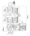
- Fig. 1 illustrates an exemplary motor drive 10 with a three phase AC input 4 receiving input power from a three-phase source 2, where the drive 10 includes a rectifier 30, an intermediate DC link circuit 40 and an output inverter 50 providing variable frequency, variable amplitude AC output power to drive a motor load 6.
- the various disclosed concepts can be employed in other forms of power conversion systems, whether providing an AC output or a DC output to drive a motor or other type of load.
- the drive input 4 has three input phase terminals which are connected through an LCL input filter circuit 20 to the AC input of the switching (active front end) rectifier 30.
- the switching rectifier 30 includes switching devices S1-S6 individually coupled between a corresponding one of the AC input phases (u, v, w) and a corresponding DC bus terminal (+ or -) of the DC link circuit 40.
- a drive controller 60 includes a rectifier switching controller 62 that provides rectifier switching control signal 62a to the rectifier switches S1-S6 to cause the rectifier 30 to convert received three-phase AC input power to provide a DC voltage Vdc across a DC bus capacitance Cdc of the link circuit 40 using any suitable pulse width modulation (PWM) technique.
- PWM pulse width modulation
- the inverter 50 receives DC input power from the link circuit 40 and includes inverter switches S7-S12 individually coupled between one of the positive or negative DC bus terminals and a corresponding output phase connected to the motor load 6.
- the inverter switches S7-S12 are operated according to inverter switching control signals 66a provided by an inverter switching component 66 of the drive controller 60, which generates the signals 66a according to any suitable pulse width modulation technique to convert DC power from the link circuit 40 to provide variable frequency, variable amplitude AC output power to the motor load 6.
- the switching rectifier 30 and the inverter 50 may employ any suitable form of switching devices S1-S12 including without limitation insulated gate bipolar transistors (IGBTs), silicon controlled rectifiers (SCRs), gate turn-off thyristors (GTOs), integrated gate commutated thyristors (IGCTs), etc.
- IGBTs insulated gate bipolar transistors
- SCRs silicon controlled rectifiers
- GTOs gate turn-off thyristors
- IGCTs integrated gate commutated thyristors
- the LCL filter circuit 20 includes three series circuits individually connected between the power converter input 4 and the corresponding phase of the rectifier AC input.
- Each series circuit includes a pair of series-connected filter inductors, with the first circuit including inductor La (e.g., a 3% inductor) connected between the first power converter input terminal and a first intermediate node "a", as well as a second filter inductor (e.g., a 9% inductor) Lu connected between the intermediate node a and a first rectifier AC input node "u".
- the second series circuit includes a first inductor Lb connected between the second motor drive input and a second intermediate node “b” and a second inductor Lv connected between the node b and the second rectifier input "v", as well as a third series circuit with first and second inductors Lc and Lw joined by a third intermediate node "c".
- the filter circuit 20 includes three capacitor circuit branches 22a, 22b and 22c respectively connecting the nodes a, b and c to a delta configuration of three filter capacitors Cab, Cbc and Cca. In this delta-connected capacitor circuit, each filter capacitor C is connected to two of the capacitor circuit branches 22 as shown.
- Fig. 2 illustrates an alternate embodiment in which a CL filter circuit 20 is provided for interfacing the motor drive 10 with the power source 2 through a transformer 3.
- the first filter inductors La, Lb and Lc are omitted due to the inductance of the secondary windings of the transformer 3, and the input terminals 4 are connected directly to the inductors Lu, Lv and Lw at the nodes a, b and c, respectively.
- the motor drive 10 includes a degradation detection system 70 coupled with the filter circuit 20, as well as a feedback circuit which senses line-to-line voltages V c.ab , V c.bc and V c.ca across the filter capacitors Cab, Cbc and Cca, for example, by sensing the voltages at the branch circuits 22 as illustrated.
- the feedback circuit includes current sensors coupled to the branch circuits 22 to sense the filter circuit branch currents I c.a , I c.b and I c.c flowing in the associated capacitor circuit branches 22a, 22b and 22c.
- the degradation detection system 70 can be any suitable hardware, processor-executed software, processor-executed firmware, programmable logic, analog circuitry, etc. which provides the described filtering, RMS computations, impedance computations and threshold comparison functionality as set forth herein, and may be operative using one or more processor elements executing computer executable instructions stored in an electronic memory of the system 70.
- the degradation detection system 70 may include one or more components, which may be implemented as software and/or firmware components in execution, programmable logic, etc., including a low pass filter/RMS computation component 72, an impedance computation component 74, as well as comparison logic operating to compare one or more computer calculated values to one or more thresholds 76.
- the degradation detection system 70 may provide a detection output signal or value 78 indicating that degradation of one or more of the filter capacitors Cab, Cbc and/or Cca has been detected by the system 70.
- the degradation detection signal 78 may be provided to the motor drive controller 60 to initiate one or more actions, such as shutting down the motor drive 10 and/or providing an alert or warning signal or other indication, for instance, to a user interface associated with the motor drive 10 and/or to a connected network (not shown).
- the degradation detection system 70 is configured to calculate fundamental frequency filter capacitor impedance values Z ab.60Hz , Z bc.60Hz and Z ca.60Hz based at least in part on the measured line-to-line voltages V c.ab , V c.bc and V c.ca and according to the sensed filter circuit branch currents I c.a , I c.b and I c.c .
- the system 70 selectively detects degradation of one or more of the filter capacitors Cab, Cbc and/or Cca according to the calculated fundamental frequency filter capacitor impedance values Z ab.60Hz , Z bc.60Hz and Z ca.60Hz .
- certain implementations of the detection system 70 individually compare the capacitor impedance values Z ab.60Hz , Z bc.60Hz and Z ca.60Hz to one or more threshold values 76, such as a lower threshold value 76 representing a nominal capacitance value minus a certain percentage as well as an upper threshold value 76 representing the nominal capacitance plus another percentage (e.g., 5-8% in one implementation) representing manufacturing tolerances, temperature drift effects, component age effects, etc. If the calculated fundamental frequency impedance value Z .60Hz of any one of the capacitors Cab, Cbc and/or Cca goes below the lower threshold or above the upper threshold, the system 70 provides the detection signal 78 to initiate a user alarm or alert and/or to shut down the motor drive 10.
- a lower threshold value 76 representing a nominal capacitance value minus a certain percentage
- an upper threshold value 76 representing the nominal capacitance plus another percentage (e.g., 5-8% in one implementation) representing manufacturing tolerances, temperature drift effects, component age effects, etc.
- the system 70 includes one or more hardware and/or processor-executed software type filters 72 which filter the line-to-line voltages V c.ab , V c.bc and V c.ca and the filter circuit branch currents I c.a , I c.b and I c.c to obtain filtered line-to-line voltages V c.ab.60hz , V c.bc.60hz and V c.ca.60hz and filtered circuit branch currents I c.a.60hz , I c.b.60hz and I c.c.60hz at a fundamental frequency of the multiphase AC input power.
- the LPF/RMS component 72 may include a low pass and/or bandpass filter or combinations thereof of any suitable order or filter type to remove frequencies above the AC input power fundamental frequency (e.g., 60 Hz in one example).
- a second order Butterworth low pass filter with a cutoff frequency of about 80 Hz to obtain the filtered line-to-line voltages V c.ab.60hz , V c.bc.60hz and V c.ca.60hz and filtered circuit branch currents I c.a.60hz , I c.b.60hz and I c.c.60hz .
- the component 72 also calculates RMS line-to-line voltages V c.ab.60hz.RMS , V c.bc.60hz.RMS and V c.ca.60hz.RMS according to the filtered line-to-line voltages V c.ab.60hz , V c.bc.60hz and V c.ca.60hz and calculates RMS circuit branch currents I c.a.60hz.RMS , I c.b.60hz.RMS and I c.c.60hz.RMS according to the filtered circuit branch currents I c.a.60hz , I c.b.60hz and I c.c.60hz . .
- the RMS computations can be according to any suitable root-mean-square formulas as are known, such as calculating the square root of the mean of the squares of a series of sampled values of the filtered voltage or current value (e.g., at the fundamental frequency).
- the illustrated embodiment of the degradation detection system 70 uses the impedance computation component 74 to calculate the fundamental frequency filter capacitor impedance values Z ab.60Hz , Z bc.60Hz and Z ca.60Hz according to the fundamental frequency RMS line-to-line voltages V c.ab.60hz.RMS , V c.bc.60hz.RMS and V c.ca.60hz.RMS and according to the fundamental frequency RMS circuit branch currents I c.a.60hz.RMS , I c.b.60hz.RMS and I c.c.60hz.RMS as described further below.
- the exemplary system 70 advantageously employs a ratio type correction factor in the computation of the fundamental frequency filter capacitor impedance values, which is derived using an artificial resistive circuit shown connected to the capacitor circuit branches 22.
- this resistive circuit is not in fact provided in the motor drive 10 (illustrated instead in dashed-lines in Fig. 3 )
- such a delta-connected resistor network including 1 ohm resistor elements Rab1, Rbc1 and Rca1 provides a useful forum for developing a correction factor used with respect to the delta-connected filter capacitors Cab, Cbc and Cca of the filter circuit 20.
- Figs. 1 ohm resistor elements Rab1, Rbc1 and Rca1 provides a useful forum for developing a correction factor used with respect to the delta-connected filter capacitors Cab, Cbc and Cca of the filter circuit 20.
- the branch circuit currents I c.a., I c.b and I c.c can be directly measured by the feedback system of the motor drive 20 (along with the sensed line-to-line voltage values V c.ab , V c.bc and V c.ca ), the leg circuit currents I c.ab., I c.bc and I c.ca actually flowing through the individual capacitors Cab, Cbc and Cca in the delta configuration would require dedicated sensors, which would add cost to the system 10 and/or which may not be feasible in view of packaging requirements for the motor drive 10.
- leg circuit currents I c.ab., I c.bc and I c.ca facilitates computation of the corresponding impedance values Z ab , Z bc and Z ca . of the filter capacitors Cab, Cbc and Cca by dividing the line-to-line voltages by the calculated leg circuit currents I c.ab , I c.bc and I c.ca .
- the inventors have appreciated that the best way to predict degradation of a capacitor is to monitor the capacitor impedance, such as by comparison by the impedance computation component 74 with one or more thresholds 76.
- the impedance based on the fundamental frequency e.g., 60 Hz
- the presence of the filter circuit 20 within a switching power conversion system 10 leads to higher frequency harmonic content.
- the fundamental frequency component will generally have the largest amplitude in a frequency spectrum, and the remainder of the significant harmonics (e.g., around 4 kHz and 8 kHz for a 4 kHz PWM switching frequency) will generally include a number of different harmonics close to one another, and are of generally lower amplitude, whereby it is more difficult to extract a signal for threshold comparison with respect to the higher order harmonics.
- the remainder of the significant harmonics e.g., around 4 kHz and 8 kHz for a 4 kHz PWM switching frequency
- the capacitance may vary a certain amount (e.g., +1.4% to -2.5%) over a relevant temperature range (e.g., -55°C to +85°C), in addition to an initial manufacturing tolerance of +/-3%, and a maximum tolerance over the operational lifetime of the capacitor component (aging tolerance), which factors can be considered in setting the threshold or thresholds 76 used for comparison with the computed filter capacitor impedance values Z ab.60Hz , Z bc.60Hz and Z ca.60Hz .
- a lower threshold 76 is set as a first constant multiplied by the initial impedance value (e.g., 0.9 in one case), and the initial value is multiplied by a second constant (e.g., 1.1) to obtain the upper threshold 76.
- the inventors have further appreciated that the delta configuration of the filter capacitors as shown in Figs. 1-3 , and the inability or undesirability of adding dedicated current sensors to measure the leg circuit currents I c.ab., I c.bc and I c.ca actually flowing through the filter capacitors Cab, Cbc and Cca, can be mitigated or overcome by carefully adjusting or compensating calculations for the real leg circuit currents I c.ab., I c.bc and I c.ca according to factors and/or parameters that can be directly measured and/or assumed.
- the inventors have developed techniques for computing the leg circuit currents I c.ab , Ic.bc and I c.ca in terms of the sensed line-to-line voltages, the sensed branch circuit currents I c.a , I c.b and I c.c as well as measured and/or assumed phase angles ⁇ bc and ⁇ ca between the line-to-line voltages V c.ab and V c.bc across the filter capacitors Cab, Cbc.
- the techniques and apparatus of the present disclosure overcome the inability or undesirability of additional dedicated filter capacitor current sensing, while providing the ability to accurately monitor the capacitance value of the filter capacitors Cab, Cbc and Cca for detection or early warning of capacitor degradation.
- the artificial delta-connected resistance circuit is coupled to the branch circuits 22a, 22b and 22c (as is the actual delta-connected filter capacitor circuitry).
- equations (1)-(4) do not exactly represent Kirchhoffs current law for the nodes of the filter circuit because Kirchhoffs current law was not written for rms values, and thus the artificial resistive circuit shown in Fig. 3 is used to derive correction factors used by the impedance computation component 74 in the motor drive 10.
- I c ⁇ 1.60 hz . calc .1 I ca ⁇ 1.60 hz . real .1 - I bc ⁇ 1.60 hz . real .1
- Ratio ab . calc .1 2. ⁇ V c . ab .60 hz . rms V c . ab .60 hz . rms - V c . ca .60 hz . rms ⁇ Cos ⁇ ca 2 + V c . ca .60 hz . rms ⁇ Sin ⁇ ca 2 + V c . bc .60 hz . rms ⁇ Cos ⁇ bc - V c . ab .60 hz .
- c .60 hz . rms Z bc .60 Hz V c . bc .60 hz . rms ⁇ Cos ⁇ bc - V c . ab .60 hz . rms 2 + V c . bc .60 hz . rms ⁇ Sin ⁇ bc 2 + V c . ca .60 hz . rms ⁇ Cos ⁇ ca - V c . bc .60 hz . rms ⁇ Cos ⁇ bc 2 + V c . bc .60 hz . rms ⁇ Cos ⁇ bc 2 + V c . bc .60 hz .
- the impedance computation component 74 employs the above equations 74ab, 74bc and 74ca ((35)-(37)) to compute the fundamental frequency filter capacitor impedance values Z ab.60Hz , Z bc.60Hz and Z ca.60Hz according to the RMS line-to-line voltages V c.ab.60hz.RMS , V c.bc.60hz.RMS and V c.ca.60hz.RMS and according to the RMS circuit branch currents I c.a.60hz.RMS , I c.b.60hz.RMS and I c.c.60hz.RMS .
- the degradation detection system 70 in certain embodiments may include a zero-crossing detection circuit operative to measure the phase angles ⁇ bc , ⁇ ca between the line-to-line voltages V c.ab and V c.bc across the filter capacitors Cab and Cbc for use in computing the fundamental frequency filter capacitor impedance values Z ab.60Hz , Z bc.60Hz and Z ca.60Hz .
- the system 70 may employ assumed values of the phase angles ⁇ bc and ⁇ ca , for example, 120° and 240°, to calculate the fundamental frequency filter capacitor impedance values Z ab.60Hz , Z bc.60Hz , Z ca.60Hz using the above equations (35)-(37).
- the inventors have appreciated that the described techniques are independent of voltage unbalance conditions, and are further advantageous in that individually calculated capacitor impedance values can be separately compared with one or more thresholds 76. Accordingly, a separate assessment of the relative health and/or degradation of the individual filter capacitors can be performed, allowing selective identification of which filter capacitor (if any) is degrading.
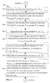
- FIG. 4 an exemplary process 100 is illustrated for detecting filter capacitor degradation in accordance with further aspects of the present disclosure.
- the process 100 begins at 102 in Fig. 4 , where line-to-line voltages V c.ab , V c.bc and V c.ca across filter capacitors Cab, Cbc and Cca are measured.
- these measured voltages are filtered to obtain filtered line-to-line voltages V c.ab.60hz , V c.bc.60hz and V c.ca.60hz at the fundamental frequency of the multiphase AC input power (e.g., 60 Hz).
- RMS line-to-line voltages V c.ab.60hz.RMS , V c.bc.60hz.RMS and V c.ca.60hz.RMS are calculated according to the filtered line-to-line voltages V c.ab.60hz , V c.bc.60hz and V c.ca.60hz .
- the filter circuit branch currents I c.a , I c.b and I c.c are measured in the capacitor circuit branches 22a, 22b, 22c, and these values are filtered at 110 and RMS values are computed at 112.
- I c.a , I c.b and I c.c are measured in the capacitor circuit branches 22a, 22b, 22c, and these values are filtered at 110 and RMS values are computed at 112.
- RMS values are computed at 112.
- phase angles ⁇ bc , ⁇ ca between the line-to-line voltages V c.ab and V c.bc across the filter capacitors Cab and Cbc can be measured or assumed as discussed above, and the ratios characterizing the real versus calculated RMS delta circuit leg current values can be computed according to the RMS line-to-line voltages at the fundamental frequency and the measured or assumed phase angles (e.g., ratios and equations (32)-(34) above).
- the process 100 further includes calculating the real delta circuit RMS filter leg currents at the fundamental frequency according to the calculated fundamental frequency currents and according to the ratios determined at 116.
- the fundamental frequency filter capacitor impedance values Z ab.60Hz , Z bc.60Hz and Z ca.60Hz are calculated based at least in part on the line-to-line voltages V c.ab , V c.bc and V c.ca and according to the filter circuit branch currents I c.a , I c.b and I c.c , and these are compared at 122 with at least one threshold 76.
- an alert is issued or the power converter is shut down if one or more of the capacitor impedance values exceeds the threshold(s), and the process 100 returns again to 102 in Fig. 4 as described above.
- FIG. 8 another motor drive power conversion system embodiment 10 is shown in Fig. 8 , with an LCL filter 20, a rectifier 30, intermediate DC link circuit 40 and inverter 50 operated by a motor drive controller 60 generally as described above to power a motor or other AC load 6 using power from an AC input source 2.
- the LCL filter 20 includes series circuits individually including two series-connected inductors (La and Lu, etc.) with corresponding capacitor circuit branches 22 connecting the series circuits with three filter capacitors Ca, Cb and Cc connected in a Y configuration with each filter capacitor C connected between a corresponding one of the capacitor circuit branches 22 and a common connection node 24.
- the feedback circuit in Figs. 8 and 9 is operative to sense capacitor voltages V c.a , V c.b and V c.c across the filter capacitors Ca, Cb and Cc (e.g., between the corresponding node a, b or c and the common connection node 24). Also, the feedback senses the filter circuit branch currents I c.a , I c.b and I c.c flowing in the capacitor circuit branches 22a, 22b and 22c.
- the filter capacitor degradation detection system 70 calculates fundamental frequency filter capacitor impedance values Z a.60Hz , Z b.60Hz and Z c.60Hz based at least partially on the capacitor voltages V c.a , V c.b and V c.c as well as the filter circuit branch currents I c.a , I c.b and I c.c , and selectively detects degradation of one or more of the filter capacitors Ca, Cb and Cc according to the calculated fundamental frequency filter capacitor impedance values Z a.60Hz , Z b.60Hz and/or Z c.60Hz . for instance, the system 70 may individually compare the computed impedance values Z a.60Hz , Z b.60Hz and Z c.60Hz with one or more thresholds 76 as described above in connection with Figs. 1-5 .
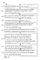
- Fig. 10 illustrates a process 300 for filter capacitor degradation detection, which may be implemented in the system 70 of Fig. 8 .
- the capacitor voltages V c.a , V c.b and V c.c are measured, and these are filtered at 304, for example, using any suitable bandpass and/or low pass filtering (e.g., second order Butterworth low pass filter with a cutoff frequency of 80 Hz in one example), in order to obtain fundamental frequency capacitor voltage values V c.a.60hz , V c.b.60hz and Vc.c.60hz.
- any suitable bandpass and/or low pass filtering e.g., second order Butterworth low pass filter with a cutoff frequency of 80 Hz in one example
- RMS values V c.a.60hz.RMS , V c.b.60hz.RMS and Vc.c.60hz.RMS of the fundamental frequency voltages are calculated, for example, using the above described or any other suitable RMS computation techniques.
- the phase currents I c.a , I c.b and I c.c are measured, and these are filtered at 310 to obtain filtered circuit branch currents I c.a.60hz , I c.b.60hz and I c.c.60hz at the input power fundamental frequency (e.g., 60 Hz).
- RMS circuit branch currents I c.a.60hz.RMS , I c.b.60hz.RMS and I c.c.60hz.RMS are calculated according to the filtered circuit branch currents I c.a.60hz , I c.b.60hz and I c.c.60hz .
- the inventors have appreciated that the RMS computations at 306 and 312 advantageously avoid situations where the sampled and filtered current fundamental frequency sinusoidal currents I c.60hz or the voltages V c.a.60hz pass through zero, causing the non-RMS ratio equation to become unreliable for determining the actual capacitor values.
- the capacitor impedance values Z a.60Hz , Z b.60Hz and Z c.60Hz are individually compared with one or more thresholds 76, and the system 70 can issue an alert is a signal or message 78 and/or shut down the drive 10 at 318 based on the threshold comparisons.
- the above embodiments and variants thereof facilitate determination of a point where one or more filter capacitors of the input filter 20 may begin to degrade, and the threshold value or values 76 can be stored in the detection system 70 in the above embodiments.
- the threshold values 76 can be determined by the system based on an initial capacitance value measurement, and/or may be set according to manufacturer's specifications including manufacturing tolerances, temperature effects, aging effects, etc.
- the calculated capacitor impedance values Z a.60Hz , Z b.60Hz and Z c.60Hz are effectively compared with initial capacitance values (measured or specified) Z c.a.initial , Z c.b.initial , Z c.c.initial , and the thresholds 76 can be determined relative to the initial values.
- the threshold values may be computed in terms of multipliers are constants multiplied by the initial impedance values.
- a lower threshold is set according to a first constant (e.g., 0.9) multiplied by the initial capacitance value, and an upper threshold 76 could be 1.1 times the initial value, with the system 70 selectively issuing a detection signal 78 if the measured impedance value falls below the lower threshold or rises above the upper threshold.
- a first constant e.g. 0.
Landscapes
- Engineering & Computer Science (AREA)
- Power Engineering (AREA)
- Inverter Devices (AREA)
- Measurement Of Resistance Or Impedance (AREA)
Applications Claiming Priority (1)
| Application Number | Priority Date | Filing Date | Title |
|---|---|---|---|
| US13/872,177 US9318944B2 (en) | 2013-04-29 | 2013-04-29 | Methods and apparatus for active front end filter capacitor degradation detection |
Publications (3)
| Publication Number | Publication Date |
|---|---|
| EP2814150A2 true EP2814150A2 (de) | 2014-12-17 |
| EP2814150A3 EP2814150A3 (de) | 2015-03-18 |
| EP2814150B1 EP2814150B1 (de) | 2020-03-11 |
Family
ID=50897343
Family Applications (1)
| Application Number | Title | Priority Date | Filing Date |
|---|---|---|---|
| EP14166343.5A Active EP2814150B1 (de) | 2013-04-29 | 2014-04-29 | Verfahren und Vorrichtung für aktive Frontfilterkondensatorverschlechterungserkennung |
Country Status (4)
| Country | Link |
|---|---|
| US (1) | US9318944B2 (de) |
| EP (1) | EP2814150B1 (de) |
| CN (1) | CN104124876B (de) |
| BR (1) | BR102014009978A2 (de) |
Cited By (1)
| Publication number | Priority date | Publication date | Assignee | Title |
|---|---|---|---|---|
| WO2016124448A1 (de) * | 2015-02-06 | 2016-08-11 | Woodward Kempen Gmbh | Filterüberwachung |
Families Citing this family (39)
| Publication number | Priority date | Publication date | Assignee | Title |
|---|---|---|---|---|
| US9653984B2 (en) | 2012-04-30 | 2017-05-16 | Rockwell Automation Technologies, Inc. | Filter capacitor degradation detection apparatus and method |
| US9318944B2 (en) | 2013-04-29 | 2016-04-19 | Rockwell Automation Technologies, Inc. | Methods and apparatus for active front end filter capacitor degradation detection |
| US20140340054A1 (en) * | 2013-05-16 | 2014-11-20 | Rockwell Automation Technologies, Inc. | Self-discharging capacitor |
| US9294005B2 (en) | 2013-10-01 | 2016-03-22 | Rockwell Automation Technologies, Inc. | Method and apparatus for detecting AFE filter capacitor degradation |
| US9651592B2 (en) | 2013-12-03 | 2017-05-16 | Rockwell Automation Technologies, Inc. | Impedance detector apparatus and method |
| US9488686B2 (en) | 2014-02-24 | 2016-11-08 | Rockwell Automation Technologies, Inc. | Filter capacitor degradation identification using computed current |
| US9490690B2 (en) * | 2014-03-11 | 2016-11-08 | Rockwell Automation Technologies, Inc. | Filter capacitor degradation identification using computed power |
| US9389263B2 (en) | 2014-06-05 | 2016-07-12 | Rockwell Automation Technologies, Inc. | Filter capacitor degradation identification using measured and expected voltage |
| JP5931148B2 (ja) * | 2014-09-10 | 2016-06-08 | ファナック株式会社 | 静電容量計算部を有するpwm整流器 |
| JP6247189B2 (ja) * | 2014-10-02 | 2017-12-13 | ファナック株式会社 | 直流リンク残留エネルギーの放電機能を有するモータ制御装置 |
| US10345348B2 (en) | 2014-11-04 | 2019-07-09 | Stmicroelectronics S.R.L. | Detection circuit for an active discharge circuit of an X-capacitor, related active discharge circuit, integrated circuit and method |
| US9735696B2 (en) * | 2015-11-25 | 2017-08-15 | Rockwell Automation Technologies, Inc. | Filter capacitor degradation and calibration |
| EP3242383A1 (de) * | 2016-05-03 | 2017-11-08 | ABB Technology Oy | Verfahren zur überwachung von kapazitätsänderungen eines wechselstromseitigen filters in einem elektrischen system und elektrisches system |
| US10272792B2 (en) * | 2016-10-28 | 2019-04-30 | Schneider Electric USA, Inc. | EVSE inadequate upstream wiring protection method |
| CN107085148B (zh) * | 2017-03-20 | 2019-08-30 | 国网江苏省电力公司无锡供电公司 | 一种并联电容器组的在线容限预警方法及装置 |
| US10396695B2 (en) | 2017-04-18 | 2019-08-27 | General Electric Company | Method for protecting an electrical power system |
| US11081891B2 (en) | 2017-05-05 | 2021-08-03 | General Electric Company | Electrical power systems having reactive power and harmonic support components |
| CN108808725B (zh) | 2017-05-05 | 2023-03-21 | 通用电气公司 | 用于风电场的无功功率控制的系统及方法 |
| US10784685B2 (en) | 2017-05-08 | 2020-09-22 | General Electric Company | Electrical power systems and subsystems |
| US10784689B2 (en) | 2017-05-08 | 2020-09-22 | General Electric Company | Electrical power systems and methods using distortion filters |
| US10587121B2 (en) | 2017-05-23 | 2020-03-10 | General Electric Company | Electrical power systems and subsystems |
| CN107092217A (zh) * | 2017-06-21 | 2017-08-25 | 中车株洲电力机车研究所有限公司 | 一种基于soc的整流回馈预测方法及装置 |
| US11152780B2 (en) * | 2017-08-31 | 2021-10-19 | Eaton Intelligent Power Limited | Adjustable speed drive with integrated solid-state circuit breaker and method of operation thereof |
| US10797589B2 (en) | 2017-09-28 | 2020-10-06 | Texas Instruments Incorporated | Methods and apparatus to compensate for power factor loss using a phasor cancellation based compensation scheme |
| US10763674B2 (en) | 2017-09-29 | 2020-09-01 | General Electric Company | System and method for controlling cluster-based wind farms |
| KR101964593B1 (ko) * | 2017-11-29 | 2019-04-02 | 한국전자통신연구원 | 전원 라인 필터의 성능 감시 장치 및 방법 |
| US10778112B2 (en) | 2018-04-04 | 2020-09-15 | General Electric Company | DFIG converter with active filter |
| JP7129552B2 (ja) * | 2019-03-22 | 2022-09-01 | 日産自動車株式会社 | 電力変換装置の制御方法及び電力変換装置 |
| US11736056B2 (en) | 2019-05-30 | 2023-08-22 | General Electric Company | System and method for controlling harmonics in a renewable energy power system |
| US11428750B1 (en) | 2019-12-12 | 2022-08-30 | Smart Wires Inc. | Monitoring non-uniform capacitor and IGBT degradation with current sensors |
| TWI721897B (zh) * | 2020-06-01 | 2021-03-11 | 台達電子工業股份有限公司 | 直流鏈電容電壓不平衡之偵測裝置 |
| JP7390621B2 (ja) * | 2020-06-25 | 2023-12-04 | パナソニックIpマネジメント株式会社 | ステッピングモータ異常検知装置 |
| US12255549B1 (en) * | 2020-10-21 | 2025-03-18 | Smart Wires Inc. | High current Voltage-Source Converter |
| CN112557788B (zh) * | 2020-11-26 | 2022-04-29 | 国网河南省电力公司电力科学研究院 | 一种考虑电网强度的并联型有源电力滤波器性能检测方法 |
| DE102021100922B4 (de) | 2021-01-18 | 2023-03-02 | Audi Aktiengesellschaft | Verfahren zur Ermittlung eines einen Gleichstrom in einem Inverter beschreibenden Gleitstromwerts, Inverteranordnung und Kraftfahrzeug |
| CN113346495B (zh) * | 2021-07-14 | 2023-04-21 | 山东博诚电气有限公司 | 一种电机控制系统和方法 |
| US12025680B2 (en) | 2021-11-16 | 2024-07-02 | City University Of Hong Kong | Method and monitoring device using the same for estimating intrinsic parameters of encapsulated capacitor |
| JP7793405B2 (ja) * | 2022-02-08 | 2026-01-05 | 株式会社東芝 | 電力変換器の診断装置、診断システム、診断方法、及び、診断プログラム |
| EP4350375B1 (de) | 2022-10-06 | 2024-12-11 | Abb Schweiz Ag | Filterkapazitätsschätzung durch resonanzfrequenzbestimmung |
Family Cites Families (55)
| Publication number | Priority date | Publication date | Assignee | Title |
|---|---|---|---|---|
| DE3020110A1 (de) * | 1980-05-27 | 1982-01-14 | Siemens AG, 1000 Berlin und 8000 München | Ueberwachungseinrichtung fuer die kondensatorbatterien eines drehstrom- filterkreises |
| US5319513A (en) | 1991-10-17 | 1994-06-07 | Trans-Coil, Inc. | Harmonic monitor and protection module |
| US5491725A (en) | 1993-09-07 | 1996-02-13 | Rockwell International Corporation | Tracking filter and quadrature-phase reference generator |
| JPH0919003A (ja) | 1995-06-27 | 1997-01-17 | Honda Motor Co Ltd | 電動車両におけるコンデンサの劣化判定装置 |
| US5796258A (en) | 1997-01-30 | 1998-08-18 | Abb Power T&D Company, Inc. | Adaptive quadrilateral characteristic distance relay |
| US6515462B2 (en) | 2000-02-10 | 2003-02-04 | Rohm Co., Ltd. | Power supply device |
| US6166929A (en) | 2000-02-29 | 2000-12-26 | Rockwell Technologies, Llc | CSI based drive having active damping control |
| US6269010B1 (en) | 2000-02-29 | 2001-07-31 | Rockwell Technologies, Llc | CSI based drive having feedforward control of inverter input voltage |
| US6366483B1 (en) | 2000-07-24 | 2002-04-02 | Rockwell Automation Technologies, Inc. | PWM rectifier having de-coupled power factor and output current control loops |
| JP4013483B2 (ja) | 2001-02-13 | 2007-11-28 | 株式会社日立製作所 | 電力変換器の制御装置 |
| US6525951B1 (en) | 2002-01-25 | 2003-02-25 | Derek Albert Paice | Simplified wye connected 3-phase to 9-phase auto-transformer |
| JP2004317345A (ja) | 2003-04-17 | 2004-11-11 | Agilent Technol Inc | 狭帯域増幅器およびインピーダンス測定装置 |
| SE0303615D0 (sv) | 2003-12-31 | 2003-12-31 | Abb Ab | Method and device for Fault Detection in Transformers |
| EP1659414A4 (de) * | 2004-06-30 | 2012-12-19 | Panasonic Corp | Verfahren zur beurteilung von kondensatorverschlechterung |
| US7782009B2 (en) | 2004-08-24 | 2010-08-24 | Rockwell Automation Technologies, Inc. | Adjustable speed drive protection |
| EP1804906A4 (de) | 2004-10-18 | 2014-09-10 | Cooper Technologies Co | Korrekturvorrichtungsschutz |
| US7495938B2 (en) | 2005-04-15 | 2009-02-24 | Rockwell Automation Technologies, Inc. | DC voltage balance control for three-level NPC power converters with even-order harmonic elimination scheme |
| US7274576B1 (en) | 2006-03-01 | 2007-09-25 | Rockwell Automation Technologies, Inc. | Power converter with reduced common mode voltage |
| EP2025051B1 (de) | 2006-06-06 | 2014-12-31 | Ideal Power Inc. | Universeller stromrichter |
| EP1870991B1 (de) | 2006-06-23 | 2014-01-15 | ABB Schweiz AG | Verfahren zum Betrieb einer Umrichterschaltung |
| US7511976B2 (en) | 2006-06-27 | 2009-03-31 | Rockwell Automation Technologies, Inc. | Self powered supply for power converter switch driver |
| PL2100365T3 (pl) | 2006-12-08 | 2019-05-31 | Siemens Ag | Kontrolowanie starzenia kondensatorów w przetwornicy za pomocą pomiaru pojemnościowego |
| US7495410B2 (en) | 2007-01-30 | 2009-02-24 | Rockwell Automation Technologies, Inc. | Systems and methods for improved motor drive power factor control |
| KR100998577B1 (ko) | 2007-08-29 | 2010-12-07 | 주식회사 와튼 | 전력변환장치의 노화상태 진단장치 및 이의 진단방법 |
| US7830269B2 (en) | 2007-09-14 | 2010-11-09 | Astec International Limited | Health monitoring for power converter capacitors |
| US7683568B2 (en) | 2007-09-28 | 2010-03-23 | Rockwell Automation Technologies, Inc. | Motor drive using flux adjustment to control power factor |
| US7800348B2 (en) | 2007-11-21 | 2010-09-21 | Rockwell Automation Technologies, Inc. | Motor drive with VAR compensation |
| US8030791B2 (en) | 2008-07-31 | 2011-10-04 | Rockwell Automation Technologies, Inc. | Current source converter-based wind energy system |
| US8009450B2 (en) | 2008-08-26 | 2011-08-30 | Rockwell Automation Technologies, Inc. | Method and apparatus for phase current balance in active converter with unbalanced AC line voltage source |
| US7990097B2 (en) | 2008-09-29 | 2011-08-02 | Rockwell Automation Technologies, Inc. | Power conversion system and method for active damping of common mode resonance |
| US8044631B2 (en) | 2008-12-30 | 2011-10-25 | Rockwell Automation Technologies, Inc. | Power conversion systems and methods for controlling harmonic distortion |
| CN201393056Y (zh) | 2009-04-28 | 2010-01-27 | 山东山大奥太电气有限公司 | 一种逆变器的保护检测装置 |
| EP2443732B1 (de) | 2009-06-18 | 2013-08-14 | ABB Technology AG | Anordnung zum austauschen von energie |
| US8898025B2 (en) | 2009-08-21 | 2014-11-25 | Vestas Wind Systems A/S | System and method for monitoring power filters and detecting power filter failure in a wind turbine electrical generator |
| US8587160B2 (en) | 2009-09-04 | 2013-11-19 | Rockwell Automation Technologies, Inc. | Grid fault ride-through for current source converter-based wind energy conversion systems |
| US8352203B2 (en) | 2009-11-30 | 2013-01-08 | Rockwell Automation Technologies, Inc. | Digital implementation of a tracking filter |
| US9054589B2 (en) | 2010-05-28 | 2015-06-09 | Rockwell Automation Technologies, Inc. | Method and apparatus for detecting power converter capacitor degradation using negative sequence currents |
| US8259426B2 (en) * | 2010-05-28 | 2012-09-04 | Rockwell Automation Technologies, Inc. | Variable frequency drive and methods for filter capacitor fault detection |
| CN103026572B (zh) | 2010-07-23 | 2015-07-01 | Abb技术有限公司 | 用于电容器组保护的方法和装置 |
| SG188439A1 (en) | 2010-10-01 | 2013-05-31 | Novartis Ag | Manufacturing process for pyrimidine derivatives |
| US8643383B2 (en) * | 2011-01-28 | 2014-02-04 | Rockwell Automation Technologies, Inc. | Drive failure protection |
| CN103328991B (zh) | 2011-02-16 | 2015-12-16 | Abb研究有限公司 | 用于y-y连接电容器组中内部故障检测的方法和装置 |
| FR2980053B1 (fr) | 2011-09-13 | 2013-10-04 | Renault Sa | Procede de surveillance du filtre capacitif d'un chargeur de batterie. |
| KR101220230B1 (ko) * | 2011-09-27 | 2013-01-09 | 카코뉴에너지 주식회사 | 계통 연계형 병렬 인버터를 이용한 태양광 발전 시스템 |
| US8816729B2 (en) | 2011-11-14 | 2014-08-26 | Rockwell Automation Technologies, Inc. | Phase-locked-loop with quadrature tracking filter for synchronizing an electric grid |
| US8704571B2 (en) | 2011-11-14 | 2014-04-22 | Rockwell Automation Technologies, Inc. | Phase-locked-loop with quadrature tracking filter for synchronizing an electric grid |
| US8729844B2 (en) | 2012-01-18 | 2014-05-20 | Hamilton Sundstrand Corporation | Power converter with asymmetric phase shift autotransformer for alternating current (AC) motor |
| JP5664589B2 (ja) | 2012-04-20 | 2015-02-04 | 株式会社安川電機 | 電源回生コンバータおよび電力変換装置 |
| US9653984B2 (en) | 2012-04-30 | 2017-05-16 | Rockwell Automation Technologies, Inc. | Filter capacitor degradation detection apparatus and method |
| US9318944B2 (en) | 2013-04-29 | 2016-04-19 | Rockwell Automation Technologies, Inc. | Methods and apparatus for active front end filter capacitor degradation detection |
| CN104283441B (zh) | 2013-07-12 | 2017-08-11 | 尼得科控制技术有限公司 | 一种直流电源及提供直流电源的方法 |
| US9294005B2 (en) | 2013-10-01 | 2016-03-22 | Rockwell Automation Technologies, Inc. | Method and apparatus for detecting AFE filter capacitor degradation |
| US9651592B2 (en) | 2013-12-03 | 2017-05-16 | Rockwell Automation Technologies, Inc. | Impedance detector apparatus and method |
| US9488686B2 (en) | 2014-02-24 | 2016-11-08 | Rockwell Automation Technologies, Inc. | Filter capacitor degradation identification using computed current |
| US9490690B2 (en) | 2014-03-11 | 2016-11-08 | Rockwell Automation Technologies, Inc. | Filter capacitor degradation identification using computed power |
-
2013
- 2013-04-29 US US13/872,177 patent/US9318944B2/en active Active
-
2014
- 2014-04-25 BR BR102014009978A patent/BR102014009978A2/pt not_active Application Discontinuation
- 2014-04-29 EP EP14166343.5A patent/EP2814150B1/de active Active
- 2014-04-29 CN CN201410177608.1A patent/CN104124876B/zh not_active Expired - Fee Related
Non-Patent Citations (1)
| Title |
|---|
| None |
Cited By (2)
| Publication number | Priority date | Publication date | Assignee | Title |
|---|---|---|---|---|
| WO2016124448A1 (de) * | 2015-02-06 | 2016-08-11 | Woodward Kempen Gmbh | Filterüberwachung |
| US10090680B2 (en) | 2015-02-06 | 2018-10-02 | Woodward Kempen Gmbh | High accuracy mains filter monitoring for a multi-phase power system |
Also Published As
| Publication number | Publication date |
|---|---|
| US20140320056A1 (en) | 2014-10-30 |
| EP2814150A3 (de) | 2015-03-18 |
| EP2814150B1 (de) | 2020-03-11 |
| CN104124876A (zh) | 2014-10-29 |
| CN104124876B (zh) | 2017-05-10 |
| BR102014009978A2 (pt) | 2015-11-17 |
| US9318944B2 (en) | 2016-04-19 |
Similar Documents
| Publication | Publication Date | Title |
|---|---|---|
| EP2814150B1 (de) | Verfahren und Vorrichtung für aktive Frontfilterkondensatorverschlechterungserkennung | |
| US9488686B2 (en) | Filter capacitor degradation identification using computed current | |
| EP2660961B1 (de) | Leistungswandler-Resonanzerkennungsvorrichtung und Verfahren | |
| US9389263B2 (en) | Filter capacitor degradation identification using measured and expected voltage | |
| US9490690B2 (en) | Filter capacitor degradation identification using computed power | |
| US9294005B2 (en) | Method and apparatus for detecting AFE filter capacitor degradation | |
| US10955489B2 (en) | System and method for ground fault detection | |
| US9653984B2 (en) | Filter capacitor degradation detection apparatus and method | |
| US8310242B2 (en) | Circuit arrangement and method for insulation monitoring for inverter applications | |
| US10302688B2 (en) | System and method for ground fault detection | |
| CN107064750A (zh) | 滤波电容器的退化及校正 | |
| EP3637115B1 (de) | Verfahren und vorrichtung zum erfassen des kapazitätswerts eines filterkondensators in einem wechselrichter | |
| US11402436B2 (en) | System and method for ground fault detection |
Legal Events
| Date | Code | Title | Description |
|---|---|---|---|
| 17P | Request for examination filed |
Effective date: 20140429 |
|
| AK | Designated contracting states |
Kind code of ref document: A2 Designated state(s): AL AT BE BG CH CY CZ DE DK EE ES FI FR GB GR HR HU IE IS IT LI LT LU LV MC MK MT NL NO PL PT RO RS SE SI SK SM TR |
|
| AX | Request for extension of the european patent |
Extension state: BA ME |
|
| PUAI | Public reference made under article 153(3) epc to a published international application that has entered the european phase |
Free format text: ORIGINAL CODE: 0009012 |
|
| PUAL | Search report despatched |
Free format text: ORIGINAL CODE: 0009013 |
|
| AK | Designated contracting states |
Kind code of ref document: A3 Designated state(s): AL AT BE BG CH CY CZ DE DK EE ES FI FR GB GR HR HU IE IS IT LI LT LU LV MC MK MT NL NO PL PT RO RS SE SI SK SM TR |
|
| AX | Request for extension of the european patent |
Extension state: BA ME |
|
| RIC1 | Information provided on ipc code assigned before grant |
Ipc: H02M 1/00 20070101AFI20150206BHEP |
|
| R17P | Request for examination filed (corrected) |
Effective date: 20150918 |
|
| RBV | Designated contracting states (corrected) |
Designated state(s): AL AT BE BG CH CY CZ DE DK EE ES FI FR GB GR HR HU IE IS IT LI LT LU LV MC MK MT NL NO PL PT RO RS SE SI SK SM TR |
|
| REG | Reference to a national code |
Ref country code: DE Ref legal event code: R079 Ref document number: 602014062072 Country of ref document: DE Free format text: PREVIOUS MAIN CLASS: H02M0001000000 Ipc: H02M0001120000 |
|
| GRAP | Despatch of communication of intention to grant a patent |
Free format text: ORIGINAL CODE: EPIDOSNIGR1 |
|
| STAA | Information on the status of an ep patent application or granted ep patent |
Free format text: STATUS: GRANT OF PATENT IS INTENDED |
|
| RIC1 | Information provided on ipc code assigned before grant |
Ipc: H02M 1/12 20060101AFI20190923BHEP Ipc: G01R 31/42 20060101ALN20190923BHEP Ipc: G01R 31/02 20060101ALN20190923BHEP |
|
| INTG | Intention to grant announced |
Effective date: 20191028 |
|
| GRAS | Grant fee paid |
Free format text: ORIGINAL CODE: EPIDOSNIGR3 |
|
| GRAA | (expected) grant |
Free format text: ORIGINAL CODE: 0009210 |
|
| STAA | Information on the status of an ep patent application or granted ep patent |
Free format text: STATUS: THE PATENT HAS BEEN GRANTED |
|
| AK | Designated contracting states |
Kind code of ref document: B1 Designated state(s): AL AT BE BG CH CY CZ DE DK EE ES FI FR GB GR HR HU IE IS IT LI LT LU LV MC MK MT NL NO PL PT RO RS SE SI SK SM TR |
|
| REG | Reference to a national code |
Ref country code: GB Ref legal event code: FG4D |
|
| REG | Reference to a national code |
Ref country code: CH Ref legal event code: EP |
|
| REG | Reference to a national code |
Ref country code: AT Ref legal event code: REF Ref document number: 1244398 Country of ref document: AT Kind code of ref document: T Effective date: 20200315 |
|
| REG | Reference to a national code |
Ref country code: IE Ref legal event code: FG4D |
|
| REG | Reference to a national code |
Ref country code: DE Ref legal event code: R096 Ref document number: 602014062072 Country of ref document: DE |
|
| PG25 | Lapsed in a contracting state [announced via postgrant information from national office to epo] |
Ref country code: RS Free format text: LAPSE BECAUSE OF FAILURE TO SUBMIT A TRANSLATION OF THE DESCRIPTION OR TO PAY THE FEE WITHIN THE PRESCRIBED TIME-LIMIT Effective date: 20200311 Ref country code: FI Free format text: LAPSE BECAUSE OF FAILURE TO SUBMIT A TRANSLATION OF THE DESCRIPTION OR TO PAY THE FEE WITHIN THE PRESCRIBED TIME-LIMIT Effective date: 20200311 Ref country code: NO Free format text: LAPSE BECAUSE OF FAILURE TO SUBMIT A TRANSLATION OF THE DESCRIPTION OR TO PAY THE FEE WITHIN THE PRESCRIBED TIME-LIMIT Effective date: 20200611 |
|
| PGFP | Annual fee paid to national office [announced via postgrant information from national office to epo] |
Ref country code: DE Payment date: 20200319 Year of fee payment: 7 Ref country code: FR Payment date: 20200421 Year of fee payment: 7 |
|
| REG | Reference to a national code |
Ref country code: NL Ref legal event code: MP Effective date: 20200311 |
|
| PG25 | Lapsed in a contracting state [announced via postgrant information from national office to epo] |
Ref country code: BG Free format text: LAPSE BECAUSE OF FAILURE TO SUBMIT A TRANSLATION OF THE DESCRIPTION OR TO PAY THE FEE WITHIN THE PRESCRIBED TIME-LIMIT Effective date: 20200611 Ref country code: HR Free format text: LAPSE BECAUSE OF FAILURE TO SUBMIT A TRANSLATION OF THE DESCRIPTION OR TO PAY THE FEE WITHIN THE PRESCRIBED TIME-LIMIT Effective date: 20200311 Ref country code: GR Free format text: LAPSE BECAUSE OF FAILURE TO SUBMIT A TRANSLATION OF THE DESCRIPTION OR TO PAY THE FEE WITHIN THE PRESCRIBED TIME-LIMIT Effective date: 20200612 Ref country code: LV Free format text: LAPSE BECAUSE OF FAILURE TO SUBMIT A TRANSLATION OF THE DESCRIPTION OR TO PAY THE FEE WITHIN THE PRESCRIBED TIME-LIMIT Effective date: 20200311 Ref country code: SE Free format text: LAPSE BECAUSE OF FAILURE TO SUBMIT A TRANSLATION OF THE DESCRIPTION OR TO PAY THE FEE WITHIN THE PRESCRIBED TIME-LIMIT Effective date: 20200311 |
|
| PGFP | Annual fee paid to national office [announced via postgrant information from national office to epo] |
Ref country code: GB Payment date: 20200422 Year of fee payment: 7 |
|
| REG | Reference to a national code |
Ref country code: LT Ref legal event code: MG4D |
|
| PG25 | Lapsed in a contracting state [announced via postgrant information from national office to epo] |
Ref country code: NL Free format text: LAPSE BECAUSE OF FAILURE TO SUBMIT A TRANSLATION OF THE DESCRIPTION OR TO PAY THE FEE WITHIN THE PRESCRIBED TIME-LIMIT Effective date: 20200311 |
|
| PG25 | Lapsed in a contracting state [announced via postgrant information from national office to epo] |
Ref country code: SK Free format text: LAPSE BECAUSE OF FAILURE TO SUBMIT A TRANSLATION OF THE DESCRIPTION OR TO PAY THE FEE WITHIN THE PRESCRIBED TIME-LIMIT Effective date: 20200311 Ref country code: EE Free format text: LAPSE BECAUSE OF FAILURE TO SUBMIT A TRANSLATION OF THE DESCRIPTION OR TO PAY THE FEE WITHIN THE PRESCRIBED TIME-LIMIT Effective date: 20200311 Ref country code: SM Free format text: LAPSE BECAUSE OF FAILURE TO SUBMIT A TRANSLATION OF THE DESCRIPTION OR TO PAY THE FEE WITHIN THE PRESCRIBED TIME-LIMIT Effective date: 20200311 Ref country code: LT Free format text: LAPSE BECAUSE OF FAILURE TO SUBMIT A TRANSLATION OF THE DESCRIPTION OR TO PAY THE FEE WITHIN THE PRESCRIBED TIME-LIMIT Effective date: 20200311 Ref country code: CZ Free format text: LAPSE BECAUSE OF FAILURE TO SUBMIT A TRANSLATION OF THE DESCRIPTION OR TO PAY THE FEE WITHIN THE PRESCRIBED TIME-LIMIT Effective date: 20200311 Ref country code: RO Free format text: LAPSE BECAUSE OF FAILURE TO SUBMIT A TRANSLATION OF THE DESCRIPTION OR TO PAY THE FEE WITHIN THE PRESCRIBED TIME-LIMIT Effective date: 20200311 Ref country code: IS Free format text: LAPSE BECAUSE OF FAILURE TO SUBMIT A TRANSLATION OF THE DESCRIPTION OR TO PAY THE FEE WITHIN THE PRESCRIBED TIME-LIMIT Effective date: 20200711 Ref country code: PT Free format text: LAPSE BECAUSE OF FAILURE TO SUBMIT A TRANSLATION OF THE DESCRIPTION OR TO PAY THE FEE WITHIN THE PRESCRIBED TIME-LIMIT Effective date: 20200805 |
|
| REG | Reference to a national code |
Ref country code: AT Ref legal event code: MK05 Ref document number: 1244398 Country of ref document: AT Kind code of ref document: T Effective date: 20200311 |
|
| REG | Reference to a national code |
Ref country code: CH Ref legal event code: PL |
|
| REG | Reference to a national code |
Ref country code: DE Ref legal event code: R097 Ref document number: 602014062072 Country of ref document: DE |
|
| PG25 | Lapsed in a contracting state [announced via postgrant information from national office to epo] |
Ref country code: MC Free format text: LAPSE BECAUSE OF FAILURE TO SUBMIT A TRANSLATION OF THE DESCRIPTION OR TO PAY THE FEE WITHIN THE PRESCRIBED TIME-LIMIT Effective date: 20200311 |
|
| PLBE | No opposition filed within time limit |
Free format text: ORIGINAL CODE: 0009261 |
|
| STAA | Information on the status of an ep patent application or granted ep patent |
Free format text: STATUS: NO OPPOSITION FILED WITHIN TIME LIMIT |
|
| PG25 | Lapsed in a contracting state [announced via postgrant information from national office to epo] |
Ref country code: DK Free format text: LAPSE BECAUSE OF FAILURE TO SUBMIT A TRANSLATION OF THE DESCRIPTION OR TO PAY THE FEE WITHIN THE PRESCRIBED TIME-LIMIT Effective date: 20200311 Ref country code: IT Free format text: LAPSE BECAUSE OF FAILURE TO SUBMIT A TRANSLATION OF THE DESCRIPTION OR TO PAY THE FEE WITHIN THE PRESCRIBED TIME-LIMIT Effective date: 20200311 Ref country code: LU Free format text: LAPSE BECAUSE OF NON-PAYMENT OF DUE FEES Effective date: 20200429 Ref country code: LI Free format text: LAPSE BECAUSE OF NON-PAYMENT OF DUE FEES Effective date: 20200430 Ref country code: ES Free format text: LAPSE BECAUSE OF FAILURE TO SUBMIT A TRANSLATION OF THE DESCRIPTION OR TO PAY THE FEE WITHIN THE PRESCRIBED TIME-LIMIT Effective date: 20200311 Ref country code: AT Free format text: LAPSE BECAUSE OF FAILURE TO SUBMIT A TRANSLATION OF THE DESCRIPTION OR TO PAY THE FEE WITHIN THE PRESCRIBED TIME-LIMIT Effective date: 20200311 Ref country code: CH Free format text: LAPSE BECAUSE OF NON-PAYMENT OF DUE FEES Effective date: 20200430 |
|
| REG | Reference to a national code |
Ref country code: BE Ref legal event code: MM Effective date: 20200430 |
|
| 26N | No opposition filed |
Effective date: 20201214 |
|
| PG25 | Lapsed in a contracting state [announced via postgrant information from national office to epo] |
Ref country code: PL Free format text: LAPSE BECAUSE OF FAILURE TO SUBMIT A TRANSLATION OF THE DESCRIPTION OR TO PAY THE FEE WITHIN THE PRESCRIBED TIME-LIMIT Effective date: 20200311 Ref country code: SI Free format text: LAPSE BECAUSE OF FAILURE TO SUBMIT A TRANSLATION OF THE DESCRIPTION OR TO PAY THE FEE WITHIN THE PRESCRIBED TIME-LIMIT Effective date: 20200311 Ref country code: BE Free format text: LAPSE BECAUSE OF NON-PAYMENT OF DUE FEES Effective date: 20200430 |
|
| PG25 | Lapsed in a contracting state [announced via postgrant information from national office to epo] |
Ref country code: IE Free format text: LAPSE BECAUSE OF NON-PAYMENT OF DUE FEES Effective date: 20200429 |
|
| REG | Reference to a national code |
Ref country code: DE Ref legal event code: R119 Ref document number: 602014062072 Country of ref document: DE |
|
| GBPC | Gb: european patent ceased through non-payment of renewal fee |
Effective date: 20210429 |
|
| PG25 | Lapsed in a contracting state [announced via postgrant information from national office to epo] |
Ref country code: DE Free format text: LAPSE BECAUSE OF NON-PAYMENT OF DUE FEES Effective date: 20211103 Ref country code: FR Free format text: LAPSE BECAUSE OF NON-PAYMENT OF DUE FEES Effective date: 20210430 Ref country code: GB Free format text: LAPSE BECAUSE OF NON-PAYMENT OF DUE FEES Effective date: 20210429 |
|
| PG25 | Lapsed in a contracting state [announced via postgrant information from national office to epo] |
Ref country code: TR Free format text: LAPSE BECAUSE OF FAILURE TO SUBMIT A TRANSLATION OF THE DESCRIPTION OR TO PAY THE FEE WITHIN THE PRESCRIBED TIME-LIMIT Effective date: 20200311 Ref country code: MT Free format text: LAPSE BECAUSE OF FAILURE TO SUBMIT A TRANSLATION OF THE DESCRIPTION OR TO PAY THE FEE WITHIN THE PRESCRIBED TIME-LIMIT Effective date: 20200311 Ref country code: CY Free format text: LAPSE BECAUSE OF FAILURE TO SUBMIT A TRANSLATION OF THE DESCRIPTION OR TO PAY THE FEE WITHIN THE PRESCRIBED TIME-LIMIT Effective date: 20200311 |
|
| PG25 | Lapsed in a contracting state [announced via postgrant information from national office to epo] |
Ref country code: MK Free format text: LAPSE BECAUSE OF FAILURE TO SUBMIT A TRANSLATION OF THE DESCRIPTION OR TO PAY THE FEE WITHIN THE PRESCRIBED TIME-LIMIT Effective date: 20200311 Ref country code: AL Free format text: LAPSE BECAUSE OF FAILURE TO SUBMIT A TRANSLATION OF THE DESCRIPTION OR TO PAY THE FEE WITHIN THE PRESCRIBED TIME-LIMIT Effective date: 20200311 |