EP2814166A1 - Onduleur multiniveau avec une pluralité des sous-modules - Google Patents
Onduleur multiniveau avec une pluralité des sous-modules Download PDFInfo
- Publication number
- EP2814166A1 EP2814166A1 EP13171312.5A EP13171312A EP2814166A1 EP 2814166 A1 EP2814166 A1 EP 2814166A1 EP 13171312 A EP13171312 A EP 13171312A EP 2814166 A1 EP2814166 A1 EP 2814166A1
- Authority
- EP
- European Patent Office
- Prior art keywords
- limb
- converter
- chain
- terminal
- link
- Prior art date
- Legal status (The legal status is an assumption and is not a legal conclusion. Google has not performed a legal analysis and makes no representation as to the accuracy of the status listed.)
- Granted
Links
Images




Classifications
-
- H—ELECTRICITY
- H02—GENERATION; CONVERSION OR DISTRIBUTION OF ELECTRIC POWER
- H02M—APPARATUS FOR CONVERSION BETWEEN AC AND AC, BETWEEN AC AND DC, OR BETWEEN DC AND DC, AND FOR USE WITH MAINS OR SIMILAR POWER SUPPLY SYSTEMS; CONVERSION OF DC OR AC INPUT POWER INTO SURGE OUTPUT POWER; CONTROL OR REGULATION THEREOF
- H02M7/00—Conversion of AC power input into DC power output; Conversion of DC power input into AC power output
- H02M7/42—Conversion of DC power input into AC power output without possibility of reversal
- H02M7/44—Conversion of DC power input into AC power output without possibility of reversal by static converters
- H02M7/48—Conversion of DC power input into AC power output without possibility of reversal by static converters using discharge tubes with control electrode or semiconductor devices with control electrode
- H02M7/483—Converters with outputs that each can have more than two voltages levels
-
- H—ELECTRICITY
- H02—GENERATION; CONVERSION OR DISTRIBUTION OF ELECTRIC POWER
- H02J—ELECTRIC POWER NETWORKS; CIRCUIT ARRANGEMENTS OR SYSTEMS FOR SUPPLYING OR DISTRIBUTING ELECTRIC POWER; SYSTEMS FOR STORING ELECTRIC ENERGY
- H02J3/00—Circuit arrangements for AC mains or AC distribution networks
- H02J3/18—Arrangements for adjusting, eliminating or compensating reactive power in networks
-
- H—ELECTRICITY
- H02—GENERATION; CONVERSION OR DISTRIBUTION OF ELECTRIC POWER
- H02M—APPARATUS FOR CONVERSION BETWEEN AC AND AC, BETWEEN AC AND DC, OR BETWEEN DC AND DC, AND FOR USE WITH MAINS OR SIMILAR POWER SUPPLY SYSTEMS; CONVERSION OF DC OR AC INPUT POWER INTO SURGE OUTPUT POWER; CONTROL OR REGULATION THEREOF
- H02M7/00—Conversion of AC power input into DC power output; Conversion of DC power input into AC power output
- H02M7/42—Conversion of DC power input into AC power output without possibility of reversal
- H02M7/44—Conversion of DC power input into AC power output without possibility of reversal by static converters
- H02M7/48—Conversion of DC power input into AC power output without possibility of reversal by static converters using discharge tubes with control electrode or semiconductor devices with control electrode
- H02M7/483—Converters with outputs that each can have more than two voltages levels
- H02M7/4835—Converters with outputs that each can have more than two voltages levels comprising two or more cells, each including a switchable capacitor, the capacitors having a nominal charge voltage which corresponds to a given fraction of the input voltage, and the capacitors being selectively connected in series to determine the instantaneous output voltage
-
- H—ELECTRICITY
- H02—GENERATION; CONVERSION OR DISTRIBUTION OF ELECTRIC POWER
- H02J—ELECTRIC POWER NETWORKS; CIRCUIT ARRANGEMENTS OR SYSTEMS FOR SUPPLYING OR DISTRIBUTING ELECTRIC POWER; SYSTEMS FOR STORING ELECTRIC ENERGY
- H02J3/00—Circuit arrangements for AC mains or AC distribution networks
- H02J3/36—Arrangements for transfer of electric power between AC networks via high-voltage DC [HVDC] links; Arrangements for transfer of electric power between generators and networks via HVDC links
-
- H—ELECTRICITY
- H02—GENERATION; CONVERSION OR DISTRIBUTION OF ELECTRIC POWER
- H02M—APPARATUS FOR CONVERSION BETWEEN AC AND AC, BETWEEN AC AND DC, OR BETWEEN DC AND DC, AND FOR USE WITH MAINS OR SIMILAR POWER SUPPLY SYSTEMS; CONVERSION OF DC OR AC INPUT POWER INTO SURGE OUTPUT POWER; CONTROL OR REGULATION THEREOF
- H02M1/00—Details of apparatus for conversion
- H02M1/0003—Details of control, feedback or regulation circuits
-
- H—ELECTRICITY
- H02—GENERATION; CONVERSION OR DISTRIBUTION OF ELECTRIC POWER
- H02M—APPARATUS FOR CONVERSION BETWEEN AC AND AC, BETWEEN AC AND DC, OR BETWEEN DC AND DC, AND FOR USE WITH MAINS OR SIMILAR POWER SUPPLY SYSTEMS; CONVERSION OF DC OR AC INPUT POWER INTO SURGE OUTPUT POWER; CONTROL OR REGULATION THEREOF
- H02M1/00—Details of apparatus for conversion
- H02M1/0095—Hybrid converter topologies, e.g. NPC mixed with flying capacitor, thyristor converter mixed with MMC or charge pump mixed with buck
-
- H—ELECTRICITY
- H02—GENERATION; CONVERSION OR DISTRIBUTION OF ELECTRIC POWER
- H02M—APPARATUS FOR CONVERSION BETWEEN AC AND AC, BETWEEN AC AND DC, OR BETWEEN DC AND DC, AND FOR USE WITH MAINS OR SIMILAR POWER SUPPLY SYSTEMS; CONVERSION OF DC OR AC INPUT POWER INTO SURGE OUTPUT POWER; CONTROL OR REGULATION THEREOF
- H02M7/00—Conversion of AC power input into DC power output; Conversion of DC power input into AC power output
- H02M7/42—Conversion of DC power input into AC power output without possibility of reversal
- H02M7/44—Conversion of DC power input into AC power output without possibility of reversal by static converters
- H02M7/48—Conversion of DC power input into AC power output without possibility of reversal by static converters using discharge tubes with control electrode or semiconductor devices with control electrode
- H02M7/483—Converters with outputs that each can have more than two voltages levels
- H02M7/49—Combination of the output voltage waveforms of a plurality of converters
Definitions
- This invention relates to an alternate arm converter for use in high voltage direct current (DC) power transmission and reactive power compensation, and a method of controlling such an alternate arm converter.
- DC direct current
- a known type of voltage source converter 10 i.e. a so-called “alternate arm converter” (AAC) 12, is shown schematically in Figure 1 .
- AAC alternate arm converter
- Such an AAC 12 typically includes first, second and third converter limbs 14a, 14b, 14c each of which is essentially identical.
- each converter limb 14a, 14b, 14c includes a first DC terminal 16a, 16b, 16c and a second DC terminal 18a, 18b, 18c, each of which is in use connected to a direct current (DC) network 20.
- Each converter limb 14a, 14b,14c also includes a respective AC terminal 22a, 22b, 22c which in use is connected to a corresponding first, second or third phase 24a, 24b, 24c of an alternating current (AC) network 26.
- AC alternating current
- each converter limb 14a, 14b, 14c defines first and second limb portions 28a, 28b, 28c, 30a, 30b, 30c, each of which extends between a respective one of the first DC terminals 16a, 16b, 16c and a corresponding AC terminal 22a, 22b, 22c, or between a respective one of the second DC terminals 18a, 18b, 18c and the corresponding AC terminal 22a 22b, 22c.
- Each limb portion 28a, 28b, 28c, 30a, 30b, 30c, or "arm" includes a single director switch 32 which is connected in series with a chain-link converter 34. In other arrangements (not shown) each limb portion may include a plurality of series-connected director switches.
- Each chain-link converter 34 includes a chain of modules 36 connected in series, with each module 36 normally including either:
- the switching elements 38 are operable so that the corresponding chain of modules 36 is able to provide a stepped variable voltage source and thereby generate a voltage waveform at the corresponding AC terminal 22a 22b, 22c.
- each limb portion 28a, 28b, 28c, 30a, 30b, 30c is operable to switch the corresponding chain-link converter 34 in and out of circuit between the respective first or second DC terminal 16a, 16b, 16c, 18a, 18b, 18c and the corresponding AC terminal 22a 22b, 22c.
- the director switch 32 of the first limb portion 28a is closed (to switch the chain-link converter 34 connected in series therewith into circuit between the first DC terminal 16a and the corresponding AC terminal 22a) and the director switch of the second limb portion 30a is opened (to switch the chain-link converter 34 connected in series therewith out of circuit between the second DC terminal 18a and the corresponding AC terminal 22a).
- the director switch 32 of the second limb portion 30a is closed (to switch the chain-link converter 34 connected in series therewith into circuit between the second DC terminal 18a and the corresponding AC terminal 22a) and the director switch of the first limb portion 28a is opened (to switch the chain-link converter 34 connected in series therewith out of circuit between the first DC terminal 16a and the corresponding AC terminal 22a).
- Such switching of the chain-link converters 34 in and out of circuit during each of the aforementioned modes reduces the voltage range that each chain-link converter 34 is required to generate, and thereby reduces the number of modules 36 needed in each chain-link converter 34 (and hence the size and cost of each chain-link converter 34).
- an optimal DC voltage V DC-opt is generated in the DC network 20 so as to help ensure that the amount of energy E + , E - transferred from the AC network 26 is equal to the amount of energy E + , E - transferred to the DC network 20.
- V DC-opt ⁇ 6 ⁇ V AC - Line - to - Line
- Transferring an equal amount of energy between the AC and DC networks 26, 20 helps to ensure that the energy stored in the chain-link converter 34 of the first limb portion 28a, 28b, 28c, of a given converter limb 14a, 14b, 14c is substantially equal to the energy stored in the chain-link converter 34 of the corresponding second limb portion 30a, 30b, 30c, e.g. as shown schematically in Figure 3(a) .
- an alternate arm converter for use in high voltage DC power transmission and reactive power compensation, the alternate arm converter comprising:
- the formation of a current circulation path connects the first and second limb portions in series with one another and in parallel with the DC network, and so allows energy to be transferred from the chain-link converter in one limb portion to the chain-link converter in the other limb portion.
- the ability to transfer energy in this manner permits a rebalancing of the energy stored in each of the said limb portions of a given converter limb, and so obviates the problems associated with such an imbalance.
- the alternating current forced to flow through the current circulation path has a zero-average waveform shape.
- Providing the alternating current flowing through the current circulation path with such a waveform shape helps to ensure that there is no net energy exchange with the DC network. This is desirable because it ensures that the only energy transfer taking place is between the respective limb portions of a given converter limb, and so helps to ensure that rebalancing of the energy stored in the limb portions is achieved in an efficient manner.
- At least one limb portion additionally includes an inductive member and the controller forces the alternating current to flow through the current circulation path by controlling one or both of the chain-link converters to generate a differential voltage across the or each inductive member.
- the or each inductive member is able to act as a current control element in order to provide accurate control of the alternating current, i.e. accurate shaping of the alternating current waveform.
- the controller is configured to switch one of the limb portions into circuit at a predetermined activation point in an operating cycle of the alternate arm converter, the controller switches both limb portions into circuit concurrently during an overlap period of the operating cycle, and the overlap period extends either side of the activation point.
- Having the overlap period extend either side of the activation point is beneficial because the extent to which a given limb portion must conduct during an opposite half-cycle is shared between the first and second limb portions, and so neither limb portion is burdened with having to support an unduly large maximum voltage.
- the controller is configured to switch the said one limb portion into circuit at a predetermined activation point at or adjacent to a point in the operating cycle at which the voltage waveform at the AC terminal passes through zero.
- Having the predetermined activation point at or adjacent to such a point in the operating cycle facilitates the handover of phase current from one converter limb to another, e.g. in a multiple phase alternate arm converter arrangement, as well as allowing some secondary control to be achieved.
- the overlap period is centred about the activation point.
- Such an arrangement helps to ensure that the extent to which a given limb portion must conduct during an opposite half-cycle is shared equally between the first and second limb portions, and so their respective configurations and voltage ratings may also be essentially the same.
- each director switch in each limb portion is or includes a make-before-break switch.
- each limb portion readily permits the formation of a current circulation path in which the first and second limb portions are connected in series with one another, and so readily facilitates the aforementioned energy transfer between the first and second limb portions.
- the controller may be configured additionally to circulate a direct current through the current circulation path to transfer energy between at least one of the chain-link converters and the DC network.
- the circulation of a direct current (in addition to the aforementioned alternating current) through the current circulation path allows the controller additionally to arrange for the exchange of energy between both the first and second limb portions of a given converter limb with the DC network.
- the ability to provide such an exchange is advantageous because it allows the controller to correct for a drift in the total, summed voltage across both chain-link converters in a given converter limb from a predetermined reference voltage, i.e. it helps the controller to ensure that the average voltage across each of the energy storage devices, e.g. capacitors, in the chain-link converters of a given converter limb are approximately equal to a reference value.
- a method of controlling an alternate arm converter including at least one converter limb having first and second DC terminals for connection in use to a DC network and an AC terminal for connection in use to an AC network, the or each converter limb defining first and second limb portions, each limb portion including at least one director switch connected in series with a chain-link converter between a respective one of the first and second DC terminals and the AC terminal, the chain-link converters being operable to generate a voltage waveform at the AC terminal, and the director switches of the first and second limb portions being operable to switch the respective chain-link converters in and out of circuit between the respective DC terminal and the AC terminal, the method comprising the steps of:
- the method of the invention shares the advantages associated with the corresponding features of the alternate arm converter of the invention.
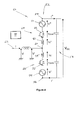
- An alternate arm converter according to a first embodiment of the invention is designated generally by reference numeral 50.
- the alternate arm converter 50 includes a converter limb 52 which has first and second DC terminals 54, 56 that in use are connected to a DC network 58, and an AC terminal 60 that in use is connected to an AC network 62.
- the alternate arm converter 50 may include more than one converter limb, and in particular may include three converter limbs, each of which is associated with a given phase of a corresponding AC network.
- the converter limb 52 defines first and second limb portions 64, 66.
- the first limb portion 64 includes a first director switch 68 which is connected in series with a first chain-link converter 70 between the first DC terminal 54 and the AC terminal 60, while the second limb portion 66 includes a second director switch 72 that is connected in series with a second chain-link converter 74.
- Each of the first and second chain-link converters 70, 74 is made up of a plurality of modules (not shown), each of which includes various switching elements arranged in parallel with an energy storage device so as to provide a switchable voltage source. As such each chain-link converter 70, 74 is able to generate a voltage waveform at the AC terminal 60.
- Each of the first and second director switches 68, 72 includes a make-before-break switch that is operable to switch the corresponding first or second chain-link converter 70, 74 in and out of circuit between the respective DC terminal 54, 56 and the AC terminal 60.
- the alternate arm converter 50 also includes a controller 90 which is configured to selectively control the switching of the first and second director switches 68, 72 during an operating cycle 76 of the converter 50.
- the controller 90 switches the director switches 68, 72 so as to allow an alternating current to flow through one or other of the first and second limb portions 64, 66.
- the chain-link converter 70, 74 in a given limb portion 64, 66 in which alternating current is selectively allowed to flow, generates a voltage V + , V - which gives rise to a converter voltage V' at the AC terminal 60, i.e. as shown in Figure 5 .
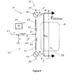
- the controller 90 is configured to switch both limb portions 64, 66 concurrently into circuit, during an overlap period 78 of the operating cycle 76, so as to form a current circulation path 80 which includes each limb portion 64, 66 and the DC network 58, as shown schematically in Figure 6 .
- the controller 90 forces an alternating current I mod to flow through the current circulation path 80.
- controller 90 forces an alternating current I mod with a zero-average waveform shape, i.e. a waveform shape which is symmetrical about a zero current axis, to flow through the current circulation path 80.
- a zero-average waveform shape i.e. a waveform shape which is symmetrical about a zero current axis
- a preferred alternating current I mod waveform shape is a square wave, as shown in Figure 7(b) .
- the zero-average waveform shape may be sinusoidal, saw-tooth, or trapezoidal.
- the controller 90 forces such an alternating current I mod to flow by controlling each of the first and second chain-link converters 70, 74 to generate a differential voltage Vs + , Vs - across a corresponding first or second inductive member 82, 84, e.g. a first or second inductor, with which the chain-link converter 70, 74 is additionally connected in series within a corresponding first or second limb portion 64, 66, as shown schematically in Figure 4 .
- the controller 90 may force such a current to flow by controlling only one of the first or second chain-link converters 70, 74 to generate a differential voltage across only one corresponding inductive member.
- the square wave alternating current I mod (as shown in Figure 7(b) ) combines with the voltage V Over+ , V Over- generated within each limb portion 64, 66 during the overlap period 78 (as shown in Figure 7(a) ) to modify the power P Over+ , P Over- generated in each limb portion 64, 66 (as shown in Figure 7(c) ) and, in turn, affect the energy stored E + , E - in the chain-link converter 70, 74 of each limb portion 64, 66 (as shown in Figure 7(d) ).
- the alternating current I mod forced to flow through the current circulation path 80 has an equal but opposite effect on the power P Over+ , P Over- generated in each limb portion 64, 66, as shown in Figure 7(c) .
- the controller 90 is configured to switch one of the limb portions, 64, 66, e.g. the second limb portion 66, into circuit at a predetermined activation point ⁇ Activation within the operating cycle 76 of the alternate arm converter 50.
- the activation point ⁇ Activation i.e. the angle within the operating cycle 76, is selected to coincide with a point in the operating cycle 76 at which the voltage at the AC terminal 60 passes through zero, as shown in Figure 8 .
- the activation point ⁇ Activation may be adjacent to the point in the operating cycle 76 at which the voltage at the AC terminal 60 passes through zero.
- Selection of the activation point ⁇ Activation is influenced by a consideration of the amount of voltage it is desired to have each limb portion 64, 66 subtract from the DC voltage V DC in order to achieve a desired converter voltage, i.e. a desired voltage V' at the AC terminal 60.
- a further consideration may be the extent to which it is desired to influence how energy is stored within each chain-link converter 70, 74 by an alternating current which can flow either through the various energy storage devices or the associated switching elements.
- the overlap period 78 extends either side of the activation point ⁇ Activation and, more particularly, the overlap period 78 is centred about the activation point ⁇ Activation .
- the duration of the overlap period 78 i.e. the length of time for which both limb portions 64, 66 are connected in series with one another within the current circulation path 80, is chosen according to how far into the opposite half-cycle of the operating cycle 76 it is desired to have each limb portion 64, 66 switched into circuit on its own, and hence according to a consideration of the maximum voltage each limb portion 64, 66 must support during such sole operation.
- a further factor in establishing the duration of the overlap period 78 is the magnitude of alternating current I mod forced to flow through the current circulation path 80 it is desired to generate during the overlap period to effect the aforementioned energy transfer between limb portions 64, 66.
- the overlap period 78 can last up to 60 electrical degrees of a 360 electrical degree operating cycle 76, but is typically less than 15 electrical degrees.
- the controller 90 may, optionally, establish a further parameter within the operating cycle 76, namely a reference point ⁇ Vconv at which the converter voltage, i.e. the voltage V' at the AC terminal 60, crosses zero on a further occasion.
- a reference point ⁇ Vconv is helpful in synchronising operation of the various components within each limb portion 64, 66, as well as operation of the limb portions 64, 66 themselves.
- the controller 90 during formation of the current circulation path 80 is also configured to circulate a direct current through the current circulation path to transfer energy E DCOver between one or both of the chain-link converters 70, 74 and the DC network, i.e. as shown schematically in Figure 9 , in order to correct any drift from a predetermined reference voltage in the total voltage across all the energy storage devices, i.e. capacitors, in the converter limb 52.
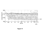
- Figure 10 illustrates the effectiveness of having the controller 90 force the alternating current I mod to flow through the current circulation path 80 to transfer energy from one limb portion to another, and thereby achieve a substantially equal balance in the energy stored (i.e. voltage level) within in each energy storage device in the first limb portion 64 and the energy stored within those of the second limb portion 66.
- the energy stored i.e. voltage level
- Figure 10 also illustrates the effectiveness of having the controller 90 additionally circulate a direct current through the current circulation path 80 to transfer energy between the limb portions 64, 66 and the DC network 58, and thereby reduce the extent to which the total voltage across all the energy storage devices in each of the first and second limb portions 64, 66 (as expressed as an average voltage across each energy storage device within a given limb portion 64, 66) drifts or deviates from a desired reference value, e.g. 1500V.
- a desired reference value e.g. 1500V.
Landscapes
- Engineering & Computer Science (AREA)
- Power Engineering (AREA)
- Rectifiers (AREA)
Priority Applications (4)
| Application Number | Priority Date | Filing Date | Title |
|---|---|---|---|
| EP13171312.5A EP2814166B1 (fr) | 2013-06-10 | 2013-06-10 | Onduleur multiniveau avec une pluralité des sous-modules |
| US14/896,907 US9755432B2 (en) | 2013-06-10 | 2014-06-06 | Alternate arm converter |
| PCT/EP2014/061916 WO2014198674A1 (fr) | 2013-06-10 | 2014-06-06 | Convertisseur a bras alterne |
| CN201480045385.1A CN105474528B (zh) | 2013-06-10 | 2014-06-06 | 变桥臂转换器 |
Applications Claiming Priority (1)
| Application Number | Priority Date | Filing Date | Title |
|---|---|---|---|
| EP13171312.5A EP2814166B1 (fr) | 2013-06-10 | 2013-06-10 | Onduleur multiniveau avec une pluralité des sous-modules |
Publications (2)
| Publication Number | Publication Date |
|---|---|
| EP2814166A1 true EP2814166A1 (fr) | 2014-12-17 |
| EP2814166B1 EP2814166B1 (fr) | 2017-11-15 |
Family
ID=48577598
Family Applications (1)
| Application Number | Title | Priority Date | Filing Date |
|---|---|---|---|
| EP13171312.5A Not-in-force EP2814166B1 (fr) | 2013-06-10 | 2013-06-10 | Onduleur multiniveau avec une pluralité des sous-modules |
Country Status (4)
| Country | Link |
|---|---|
| US (1) | US9755432B2 (fr) |
| EP (1) | EP2814166B1 (fr) |
| CN (1) | CN105474528B (fr) |
| WO (1) | WO2014198674A1 (fr) |
Cited By (6)
| Publication number | Priority date | Publication date | Assignee | Title |
|---|---|---|---|---|
| CN105119509A (zh) * | 2015-07-23 | 2015-12-02 | 上海电力设计院有限公司 | 适用于不对称交流电网的mmc直接环流抑制方法 |
| EP3048688A1 (fr) * | 2015-01-22 | 2016-07-27 | General Electric Technology GmbH | Améliorations apportées ou relatives à des convertisseurs de puissance à courant continu à haute tension |
| GB2537608A (en) * | 2015-04-17 | 2016-10-26 | General Electric Technology Gmbh | Improvements in or relating to voltage source converters |
| WO2017021497A1 (fr) * | 2015-08-05 | 2017-02-09 | General Electric Technology Gmbh | Convertisseur de source de tension |
| WO2017029171A1 (fr) * | 2015-08-19 | 2017-02-23 | General Electric Technology Gmbh | Convertisseur de source de tension |
| CN111277152A (zh) * | 2018-12-03 | 2020-06-12 | 法国电力公司 | 交替臂电流源转换器,功率转换系统以及用于控制这种转换器的方法 |
Families Citing this family (7)
| Publication number | Priority date | Publication date | Assignee | Title |
|---|---|---|---|---|
| EP2755315A1 (fr) | 2013-01-11 | 2014-07-16 | Alstom Technology Ltd | Convertisseur hybride et modulaire |
| EP2944016A2 (fr) * | 2013-01-11 | 2015-11-18 | Alstom Technology Ltd | Convertisseur de source de tension |
| EP2887529A1 (fr) | 2013-12-23 | 2015-06-24 | Alstom Technology Ltd | Module de phase d'un convertisseur modulaire multi-niveaux avec flat-top MLI, convertisseur et circuit convertisseurs hybrides |
| EP3062413A1 (fr) * | 2015-02-27 | 2016-08-31 | Alstom Technology Ltd | Convertisseur de source de tension et commande de celui-ci |
| GB2547936A (en) * | 2016-03-03 | 2017-09-06 | General Electric Technology Gmbh | Fault protection for voltage source converters |
| GB2566933B (en) | 2017-09-15 | 2022-09-07 | Turbo Power Systems Ltd | Sub-statioin transformer load balancing system |
| EP3654519A1 (fr) * | 2018-11-14 | 2020-05-20 | General Electric Company | Convertisseur de source de tension |
Citations (1)
| Publication number | Priority date | Publication date | Assignee | Title |
|---|---|---|---|---|
| WO2012055435A1 (fr) * | 2010-10-27 | 2012-05-03 | Alstom Grid Uk Limited | Convertisseur modulaire à niveaux multiples |
Family Cites Families (7)
| Publication number | Priority date | Publication date | Assignee | Title |
|---|---|---|---|---|
| EP2100364B1 (fr) | 2006-12-08 | 2018-09-12 | Siemens Aktiengesellschaft | Commande d'un convertisseur modulaire avec des accumulateurs d'énergie répartis |
| JP5141688B2 (ja) | 2007-09-06 | 2013-02-13 | 富士通株式会社 | 音信号生成方法、音信号生成装置及びコンピュータプログラム |
| CA2764504C (fr) | 2009-06-15 | 2016-08-23 | David Trainer | Convertisseur de source de tension c.c. |
| WO2010149200A1 (fr) | 2009-06-22 | 2010-12-29 | Areva T&D Uk Limited | Convertisseur |
| WO2011113471A1 (fr) * | 2010-03-15 | 2011-09-22 | Areva T&D Uk Ltd | Compensateur statique de puissance réactive doté d'un convertisseur à plusieurs niveaux |
| EP2727234B1 (fr) * | 2011-06-29 | 2016-09-14 | General Electric Technology GmbH | Convertisseur |
| US9484808B2 (en) * | 2011-08-24 | 2016-11-01 | Abb Schweiz Ag | Bidirectional unisolated DC-DC converter based on cascaded cells |
-
2013
- 2013-06-10 EP EP13171312.5A patent/EP2814166B1/fr not_active Not-in-force
-
2014
- 2014-06-06 US US14/896,907 patent/US9755432B2/en not_active Expired - Fee Related
- 2014-06-06 CN CN201480045385.1A patent/CN105474528B/zh not_active Expired - Fee Related
- 2014-06-06 WO PCT/EP2014/061916 patent/WO2014198674A1/fr not_active Ceased
Patent Citations (1)
| Publication number | Priority date | Publication date | Assignee | Title |
|---|---|---|---|---|
| WO2012055435A1 (fr) * | 2010-10-27 | 2012-05-03 | Alstom Grid Uk Limited | Convertisseur modulaire à niveaux multiples |
Non-Patent Citations (1)
| Title |
|---|
| ANTONIOS ANTONOPOULOS ET AL: "On dynamics and voltage control of the Modular Multilevel Converter", 13TH EUROPEAN CONFERENCE ON POWER ELECTRONICS AND APPLICATIONS, 2009 : EPE '09 ; 8 - 10 SEPT. 2009, BARCELONA, SPAIN, IEEE, PISCATAWAY, NJ, USA, 8 September 2009 (2009-09-08), pages 1 - 10, XP031541295, ISBN: 978-1-4244-4432-8 * |
Cited By (11)
| Publication number | Priority date | Publication date | Assignee | Title |
|---|---|---|---|---|
| EP3048688A1 (fr) * | 2015-01-22 | 2016-07-27 | General Electric Technology GmbH | Améliorations apportées ou relatives à des convertisseurs de puissance à courant continu à haute tension |
| WO2016116573A1 (fr) * | 2015-01-22 | 2016-07-28 | General Electric Technology Gmbh | Améliorations apportées à des convertisseurs de courant continu à haute tension ou relatives à ceux-ci |
| GB2537608A (en) * | 2015-04-17 | 2016-10-26 | General Electric Technology Gmbh | Improvements in or relating to voltage source converters |
| GB2537608B (en) * | 2015-04-17 | 2019-05-22 | General Electric Technology Gmbh | Improvements in or relating to voltage source converters |
| CN105119509A (zh) * | 2015-07-23 | 2015-12-02 | 上海电力设计院有限公司 | 适用于不对称交流电网的mmc直接环流抑制方法 |
| CN105119509B (zh) * | 2015-07-23 | 2017-10-31 | 上海电力设计院有限公司 | 适用于不对称交流电网的mmc直接环流抑制方法 |
| WO2017021497A1 (fr) * | 2015-08-05 | 2017-02-09 | General Electric Technology Gmbh | Convertisseur de source de tension |
| CN107852105A (zh) * | 2015-08-05 | 2018-03-27 | 通用电器技术有限公司 | 电压源转换器 |
| WO2017029171A1 (fr) * | 2015-08-19 | 2017-02-23 | General Electric Technology Gmbh | Convertisseur de source de tension |
| CN107925364A (zh) * | 2015-08-19 | 2018-04-17 | 通用电器技术有限公司 | 电压源转换器 |
| CN111277152A (zh) * | 2018-12-03 | 2020-06-12 | 法国电力公司 | 交替臂电流源转换器,功率转换系统以及用于控制这种转换器的方法 |
Also Published As
| Publication number | Publication date |
|---|---|
| CN105474528A (zh) | 2016-04-06 |
| US20160141876A1 (en) | 2016-05-19 |
| EP2814166B1 (fr) | 2017-11-15 |
| US9755432B2 (en) | 2017-09-05 |
| CN105474528B (zh) | 2018-08-03 |
| WO2014198674A1 (fr) | 2014-12-18 |
Similar Documents
| Publication | Publication Date | Title |
|---|---|---|
| EP2814166B1 (fr) | Onduleur multiniveau avec une pluralité des sous-modules | |
| US11038435B2 (en) | Converter, electrical polyphase system and method for efficient power exchange | |
| CN106030955B (zh) | 包括模块化多电平转换器的能量存储系统 | |
| EP2863534B1 (fr) | Convertisseur de source de tension | |
| US8929111B2 (en) | System and method for common-mode elimination in a multi-level converter | |
| US10079558B2 (en) | Switching scheme for static synchronous compensators using cascaded H-bridge converters | |
| CN103875147B (zh) | 多电平变换器及用于控制包括平衡单元电压的多电平变换器的方法 | |
| JP4898898B2 (ja) | 3相電力変換装置 | |
| US9876358B2 (en) | Converter arrangement for power compensation and a method for controlling a power converter | |
| US10110110B2 (en) | Power conversion device | |
| JP2018537945A (ja) | モジュラーマルチレベルコンバータの能動的放電 | |
| US12057787B2 (en) | Power conversion device | |
| CN110603704A (zh) | 基于vsc的hvdc换流器的dc电流控制 | |
| EP2947741A1 (fr) | Circuit de commande | |
| EP3826165B1 (fr) | Améliorations apportées ou se rapportant à des convertisseurs de dissipation d'énergie | |
| JP2018011413A (ja) | 電力変換装置 | |
| US20190372479A1 (en) | Voltage source converter | |
| US20180233916A1 (en) | Voltage source converter | |
| JP6337659B2 (ja) | 5レベル電力変換装置 | |
| JP5478367B2 (ja) | パワーコンバータ | |
| GB2519762A (en) | DC to DC converter assembly | |
| US20190013742A1 (en) | Voltage source converter | |
| EP3382880A1 (fr) | Améliorations apportées ou se rapportant aux commandes de convertisseurs de source de tension | |
| EP3284166A1 (fr) | Convertisseur multiniveaux modulaire hybride avec vannes directrices |
Legal Events
| Date | Code | Title | Description |
|---|---|---|---|
| 17P | Request for examination filed |
Effective date: 20130610 |
|
| AK | Designated contracting states |
Kind code of ref document: A1 Designated state(s): AL AT BE BG CH CY CZ DE DK EE ES FI FR GB GR HR HU IE IS IT LI LT LU LV MC MK MT NL NO PL PT RO RS SE SI SK SM TR |
|
| AX | Request for extension of the european patent |
Extension state: BA ME |
|
| PUAI | Public reference made under article 153(3) epc to a published international application that has entered the european phase |
Free format text: ORIGINAL CODE: 0009012 |
|
| R17P | Request for examination filed (corrected) |
Effective date: 20150616 |
|
| RBV | Designated contracting states (corrected) |
Designated state(s): AL AT BE BG CH CY CZ DE DK EE ES FI FR GB GR HR HU IE IS IT LI LT LU LV MC MK MT NL NO PL PT RO RS SE SI SK SM TR |
|
| 17Q | First examination report despatched |
Effective date: 20150723 |
|
| RAP1 | Party data changed (applicant data changed or rights of an application transferred) |
Owner name: GENERAL ELECTRIC TECHNOLOGY GMBH |
|
| GRAP | Despatch of communication of intention to grant a patent |
Free format text: ORIGINAL CODE: EPIDOSNIGR1 |
|
| STAA | Information on the status of an ep patent application or granted ep patent |
Free format text: STATUS: GRANT OF PATENT IS INTENDED |
|
| INTG | Intention to grant announced |
Effective date: 20170412 |
|
| GRAJ | Information related to disapproval of communication of intention to grant by the applicant or resumption of examination proceedings by the epo deleted |
Free format text: ORIGINAL CODE: EPIDOSDIGR1 |
|
| STAA | Information on the status of an ep patent application or granted ep patent |
Free format text: STATUS: EXAMINATION IS IN PROGRESS |
|
| INTC | Intention to grant announced (deleted) | ||
| GRAJ | Information related to disapproval of communication of intention to grant by the applicant or resumption of examination proceedings by the epo deleted |
Free format text: ORIGINAL CODE: EPIDOSDIGR1 |
|
| GRAP | Despatch of communication of intention to grant a patent |
Free format text: ORIGINAL CODE: EPIDOSNIGR1 |
|
| GRAR | Information related to intention to grant a patent recorded |
Free format text: ORIGINAL CODE: EPIDOSNIGR71 |
|
| GRAS | Grant fee paid |
Free format text: ORIGINAL CODE: EPIDOSNIGR3 |
|
| STAA | Information on the status of an ep patent application or granted ep patent |
Free format text: STATUS: GRANT OF PATENT IS INTENDED |
|
| GRAA | (expected) grant |
Free format text: ORIGINAL CODE: 0009210 |
|
| STAA | Information on the status of an ep patent application or granted ep patent |
Free format text: STATUS: THE PATENT HAS BEEN GRANTED |
|
| AK | Designated contracting states |
Kind code of ref document: B1 Designated state(s): AL AT BE BG CH CY CZ DE DK EE ES FI FR GB GR HR HU IE IS IT LI LT LU LV MC MK MT NL NO PL PT RO RS SE SI SK SM TR |
|
| INTG | Intention to grant announced |
Effective date: 20171009 |
|
| REG | Reference to a national code |
Ref country code: CH Ref legal event code: EP Ref country code: GB Ref legal event code: FG4D Ref country code: AT Ref legal event code: REF Ref document number: 947198 Country of ref document: AT Kind code of ref document: T Effective date: 20171115 |
|
| REG | Reference to a national code |
Ref country code: IE Ref legal event code: FG4D |
|
| REG | Reference to a national code |
Ref country code: DE Ref legal event code: R096 Ref document number: 602013029372 Country of ref document: DE |
|
| REG | Reference to a national code |
Ref country code: SE Ref legal event code: TRGR |
|
| REG | Reference to a national code |
Ref country code: NL Ref legal event code: MP Effective date: 20171115 |
|
| REG | Reference to a national code |
Ref country code: LT Ref legal event code: MG4D |
|
| REG | Reference to a national code |
Ref country code: AT Ref legal event code: MK05 Ref document number: 947198 Country of ref document: AT Kind code of ref document: T Effective date: 20171115 |
|
| PG25 | Lapsed in a contracting state [announced via postgrant information from national office to epo] |
Ref country code: ES Free format text: LAPSE BECAUSE OF FAILURE TO SUBMIT A TRANSLATION OF THE DESCRIPTION OR TO PAY THE FEE WITHIN THE PRESCRIBED TIME-LIMIT Effective date: 20171115 Ref country code: LT Free format text: LAPSE BECAUSE OF FAILURE TO SUBMIT A TRANSLATION OF THE DESCRIPTION OR TO PAY THE FEE WITHIN THE PRESCRIBED TIME-LIMIT Effective date: 20171115 Ref country code: NO Free format text: LAPSE BECAUSE OF FAILURE TO SUBMIT A TRANSLATION OF THE DESCRIPTION OR TO PAY THE FEE WITHIN THE PRESCRIBED TIME-LIMIT Effective date: 20180215 Ref country code: NL Free format text: LAPSE BECAUSE OF FAILURE TO SUBMIT A TRANSLATION OF THE DESCRIPTION OR TO PAY THE FEE WITHIN THE PRESCRIBED TIME-LIMIT Effective date: 20171115 Ref country code: FI Free format text: LAPSE BECAUSE OF FAILURE TO SUBMIT A TRANSLATION OF THE DESCRIPTION OR TO PAY THE FEE WITHIN THE PRESCRIBED TIME-LIMIT Effective date: 20171115 |
|
| PG25 | Lapsed in a contracting state [announced via postgrant information from national office to epo] |
Ref country code: AT Free format text: LAPSE BECAUSE OF FAILURE TO SUBMIT A TRANSLATION OF THE DESCRIPTION OR TO PAY THE FEE WITHIN THE PRESCRIBED TIME-LIMIT Effective date: 20171115 Ref country code: LV Free format text: LAPSE BECAUSE OF FAILURE TO SUBMIT A TRANSLATION OF THE DESCRIPTION OR TO PAY THE FEE WITHIN THE PRESCRIBED TIME-LIMIT Effective date: 20171115 Ref country code: RS Free format text: LAPSE BECAUSE OF FAILURE TO SUBMIT A TRANSLATION OF THE DESCRIPTION OR TO PAY THE FEE WITHIN THE PRESCRIBED TIME-LIMIT Effective date: 20171115 Ref country code: GR Free format text: LAPSE BECAUSE OF FAILURE TO SUBMIT A TRANSLATION OF THE DESCRIPTION OR TO PAY THE FEE WITHIN THE PRESCRIBED TIME-LIMIT Effective date: 20180216 Ref country code: HR Free format text: LAPSE BECAUSE OF FAILURE TO SUBMIT A TRANSLATION OF THE DESCRIPTION OR TO PAY THE FEE WITHIN THE PRESCRIBED TIME-LIMIT Effective date: 20171115 Ref country code: BG Free format text: LAPSE BECAUSE OF FAILURE TO SUBMIT A TRANSLATION OF THE DESCRIPTION OR TO PAY THE FEE WITHIN THE PRESCRIBED TIME-LIMIT Effective date: 20180215 |
|
| REG | Reference to a national code |
Ref country code: FR Ref legal event code: PLFP Year of fee payment: 6 |
|
| PG25 | Lapsed in a contracting state [announced via postgrant information from national office to epo] |
Ref country code: CZ Free format text: LAPSE BECAUSE OF FAILURE TO SUBMIT A TRANSLATION OF THE DESCRIPTION OR TO PAY THE FEE WITHIN THE PRESCRIBED TIME-LIMIT Effective date: 20171115 Ref country code: CY Free format text: LAPSE BECAUSE OF FAILURE TO SUBMIT A TRANSLATION OF THE DESCRIPTION OR TO PAY THE FEE WITHIN THE PRESCRIBED TIME-LIMIT Effective date: 20171115 Ref country code: EE Free format text: LAPSE BECAUSE OF FAILURE TO SUBMIT A TRANSLATION OF THE DESCRIPTION OR TO PAY THE FEE WITHIN THE PRESCRIBED TIME-LIMIT Effective date: 20171115 Ref country code: SK Free format text: LAPSE BECAUSE OF FAILURE TO SUBMIT A TRANSLATION OF THE DESCRIPTION OR TO PAY THE FEE WITHIN THE PRESCRIBED TIME-LIMIT Effective date: 20171115 Ref country code: DK Free format text: LAPSE BECAUSE OF FAILURE TO SUBMIT A TRANSLATION OF THE DESCRIPTION OR TO PAY THE FEE WITHIN THE PRESCRIBED TIME-LIMIT Effective date: 20171115 |
|
| REG | Reference to a national code |
Ref country code: DE Ref legal event code: R097 Ref document number: 602013029372 Country of ref document: DE |
|
| PG25 | Lapsed in a contracting state [announced via postgrant information from national office to epo] |
Ref country code: RO Free format text: LAPSE BECAUSE OF FAILURE TO SUBMIT A TRANSLATION OF THE DESCRIPTION OR TO PAY THE FEE WITHIN THE PRESCRIBED TIME-LIMIT Effective date: 20171115 Ref country code: PL Free format text: LAPSE BECAUSE OF FAILURE TO SUBMIT A TRANSLATION OF THE DESCRIPTION OR TO PAY THE FEE WITHIN THE PRESCRIBED TIME-LIMIT Effective date: 20171115 Ref country code: SM Free format text: LAPSE BECAUSE OF FAILURE TO SUBMIT A TRANSLATION OF THE DESCRIPTION OR TO PAY THE FEE WITHIN THE PRESCRIBED TIME-LIMIT Effective date: 20171115 Ref country code: IT Free format text: LAPSE BECAUSE OF FAILURE TO SUBMIT A TRANSLATION OF THE DESCRIPTION OR TO PAY THE FEE WITHIN THE PRESCRIBED TIME-LIMIT Effective date: 20171115 |
|
| PGFP | Annual fee paid to national office [announced via postgrant information from national office to epo] |
Ref country code: FR Payment date: 20180626 Year of fee payment: 6 |
|
| PLBE | No opposition filed within time limit |
Free format text: ORIGINAL CODE: 0009261 |
|
| STAA | Information on the status of an ep patent application or granted ep patent |
Free format text: STATUS: NO OPPOSITION FILED WITHIN TIME LIMIT |
|
| PGFP | Annual fee paid to national office [announced via postgrant information from national office to epo] |
Ref country code: SE Payment date: 20180627 Year of fee payment: 6 |
|
| 26N | No opposition filed |
Effective date: 20180817 |
|
| PGFP | Annual fee paid to national office [announced via postgrant information from national office to epo] |
Ref country code: GB Payment date: 20180627 Year of fee payment: 6 Ref country code: DE Payment date: 20180627 Year of fee payment: 6 |
|
| PG25 | Lapsed in a contracting state [announced via postgrant information from national office to epo] |
Ref country code: SI Free format text: LAPSE BECAUSE OF FAILURE TO SUBMIT A TRANSLATION OF THE DESCRIPTION OR TO PAY THE FEE WITHIN THE PRESCRIBED TIME-LIMIT Effective date: 20171115 |
|
| REG | Reference to a national code |
Ref country code: CH Ref legal event code: PL |
|
| REG | Reference to a national code |
Ref country code: BE Ref legal event code: MM Effective date: 20180630 |
|
| REG | Reference to a national code |
Ref country code: IE Ref legal event code: MM4A |
|
| PG25 | Lapsed in a contracting state [announced via postgrant information from national office to epo] |
Ref country code: MC Free format text: LAPSE BECAUSE OF FAILURE TO SUBMIT A TRANSLATION OF THE DESCRIPTION OR TO PAY THE FEE WITHIN THE PRESCRIBED TIME-LIMIT Effective date: 20171115 Ref country code: LU Free format text: LAPSE BECAUSE OF NON-PAYMENT OF DUE FEES Effective date: 20180610 |
|
| PG25 | Lapsed in a contracting state [announced via postgrant information from national office to epo] |
Ref country code: IE Free format text: LAPSE BECAUSE OF NON-PAYMENT OF DUE FEES Effective date: 20180610 Ref country code: LI Free format text: LAPSE BECAUSE OF NON-PAYMENT OF DUE FEES Effective date: 20180630 Ref country code: CH Free format text: LAPSE BECAUSE OF NON-PAYMENT OF DUE FEES Effective date: 20180630 |
|
| PG25 | Lapsed in a contracting state [announced via postgrant information from national office to epo] |
Ref country code: BE Free format text: LAPSE BECAUSE OF NON-PAYMENT OF DUE FEES Effective date: 20180630 |
|
| REG | Reference to a national code |
Ref country code: DE Ref legal event code: R119 Ref document number: 602013029372 Country of ref document: DE |
|
| REG | Reference to a national code |
Ref country code: SE Ref legal event code: EUG |
|
| PG25 | Lapsed in a contracting state [announced via postgrant information from national office to epo] |
Ref country code: MT Free format text: LAPSE BECAUSE OF NON-PAYMENT OF DUE FEES Effective date: 20180610 Ref country code: SE Free format text: LAPSE BECAUSE OF NON-PAYMENT OF DUE FEES Effective date: 20190611 |
|
| GBPC | Gb: european patent ceased through non-payment of renewal fee |
Effective date: 20190610 |
|
| PG25 | Lapsed in a contracting state [announced via postgrant information from national office to epo] |
Ref country code: TR Free format text: LAPSE BECAUSE OF FAILURE TO SUBMIT A TRANSLATION OF THE DESCRIPTION OR TO PAY THE FEE WITHIN THE PRESCRIBED TIME-LIMIT Effective date: 20171115 |
|
| PG25 | Lapsed in a contracting state [announced via postgrant information from national office to epo] |
Ref country code: GB Free format text: LAPSE BECAUSE OF NON-PAYMENT OF DUE FEES Effective date: 20190610 Ref country code: DE Free format text: LAPSE BECAUSE OF NON-PAYMENT OF DUE FEES Effective date: 20200101 |
|
| PG25 | Lapsed in a contracting state [announced via postgrant information from national office to epo] |
Ref country code: PT Free format text: LAPSE BECAUSE OF FAILURE TO SUBMIT A TRANSLATION OF THE DESCRIPTION OR TO PAY THE FEE WITHIN THE PRESCRIBED TIME-LIMIT Effective date: 20171115 Ref country code: HU Free format text: LAPSE BECAUSE OF FAILURE TO SUBMIT A TRANSLATION OF THE DESCRIPTION OR TO PAY THE FEE WITHIN THE PRESCRIBED TIME-LIMIT; INVALID AB INITIO Effective date: 20130610 |
|
| PG25 | Lapsed in a contracting state [announced via postgrant information from national office to epo] |
Ref country code: FR Free format text: LAPSE BECAUSE OF NON-PAYMENT OF DUE FEES Effective date: 20190630 Ref country code: MK Free format text: LAPSE BECAUSE OF NON-PAYMENT OF DUE FEES Effective date: 20171115 |
|
| PG25 | Lapsed in a contracting state [announced via postgrant information from national office to epo] |
Ref country code: AL Free format text: LAPSE BECAUSE OF FAILURE TO SUBMIT A TRANSLATION OF THE DESCRIPTION OR TO PAY THE FEE WITHIN THE PRESCRIBED TIME-LIMIT Effective date: 20171115 Ref country code: IS Free format text: LAPSE BECAUSE OF FAILURE TO SUBMIT A TRANSLATION OF THE DESCRIPTION OR TO PAY THE FEE WITHIN THE PRESCRIBED TIME-LIMIT Effective date: 20180315 |