EP2814235A1 - Kameravorrichtung mit Diffusor und entsprechendes Verfahren - Google Patents
Kameravorrichtung mit Diffusor und entsprechendes Verfahren Download PDFInfo
- Publication number
- EP2814235A1 EP2814235A1 EP13172064.1A EP13172064A EP2814235A1 EP 2814235 A1 EP2814235 A1 EP 2814235A1 EP 13172064 A EP13172064 A EP 13172064A EP 2814235 A1 EP2814235 A1 EP 2814235A1
- Authority
- EP
- European Patent Office
- Prior art keywords
- camera device
- diffuser
- camera
- lens
- housing
- Prior art date
- Legal status (The legal status is an assumption and is not a legal conclusion. Google has not performed a legal analysis and makes no representation as to the accuracy of the status listed.)
- Withdrawn
Links
- 238000000034 method Methods 0.000 title claims abstract description 8
- 230000003287 optical effect Effects 0.000 description 3
- 229920000642 polymer Polymers 0.000 description 3
- 239000004698 Polyethylene Substances 0.000 description 2
- 238000010586 diagram Methods 0.000 description 2
- 230000000694 effects Effects 0.000 description 2
- 239000000463 material Substances 0.000 description 2
- 239000000203 mixture Substances 0.000 description 2
- 229920000573 polyethylene Polymers 0.000 description 2
- 241000593989 Scardinius erythrophthalmus Species 0.000 description 1
- 230000004308 accommodation Effects 0.000 description 1
- 239000000654 additive Substances 0.000 description 1
- 230000000903 blocking effect Effects 0.000 description 1
- 239000003086 colorant Substances 0.000 description 1
- 230000006870 function Effects 0.000 description 1
- 239000011521 glass Substances 0.000 description 1
- 238000003384 imaging method Methods 0.000 description 1
- 230000006855 networking Effects 0.000 description 1
- 201000005111 ocular hyperemia Diseases 0.000 description 1
- -1 polyethylene Polymers 0.000 description 1
- 239000004800 polyvinyl chloride Substances 0.000 description 1
- 239000000758 substrate Substances 0.000 description 1
Images



Classifications
-
- H—ELECTRICITY
- H04—ELECTRIC COMMUNICATION TECHNIQUE
- H04N—PICTORIAL COMMUNICATION, e.g. TELEVISION
- H04N23/00—Cameras or camera modules comprising electronic image sensors; Control thereof
- H04N23/56—Cameras or camera modules comprising electronic image sensors; Control thereof provided with illuminating means
-
- H—ELECTRICITY
- H04—ELECTRIC COMMUNICATION TECHNIQUE
- H04N—PICTORIAL COMMUNICATION, e.g. TELEVISION
- H04N23/00—Cameras or camera modules comprising electronic image sensors; Control thereof
- H04N23/70—Circuitry for compensating brightness variation in the scene
- H04N23/74—Circuitry for compensating brightness variation in the scene by influencing the scene brightness using illuminating means
Definitions
- the present invention relates to a method and a camera device comprising a flash arrangement and a diffuser.
- the flash arrangement and the diffuser are configured to emit diffused light for creating a substantially uniform distributed flash light, in particular for avoiding unwanted shadowing effects and red-eye effects of the human target.
- images must be taken at times where the image objects have a desired appearance. For example, it may be desired to take pictures of smiling persons and to avoid closed eyes.
- a camera device comprising a camera housing with a center axis and having a first surface and a second surface.
- the camera device comprises a sensor arrangement for image capturing and a lens housing having a first lens housing surface with a lens opening.
- the camera device comprises a flash arrangement comprising one or a plurality of Light Emitting Diode (LED) elements including at least a first LED element configured to emit light with a first intensity profile, and optionally a second LED element configured to emit light with a second intensity profile.
- the flash arrangement may be arranged between the first lens housing surface and the second surface of the camera housing, and the camera device comprises a diffuser optionally mounted distal to and covering the plurality of LED elements.
- Also disclosed is a method of capturing an image with a camera device comprising emitting light from a flash arrangement comprising a plurality of LED elements including at least a first LED element and at least a second LED element, the flash arrangement being arranged between a first lens housing surface of a lens housing and a second surface of a camera housing; and diffusing the emitted light by a diffuser distal to and covering the plurality of LED elements.
- the emitted light from the plurality of LED elements will not come from a number of concentrated sources/points, but rather will spread out, due to internal reflection of the emitted light in the diffuser, thus reducing or substantially eliminating harsh light and hard shadows.
- This is particularly useful for portrait photographers, since harsh light and hard shadows are usually not considered flattering in a portrait.
- the camera device allows for convenient user indication by using the flash arrangement with the diffuser for indicating operating parameters of the camera to an image object or target.
- the present invention relates to a method and a camera device comprising a flash arrangement and a diffuser, wherein the flash arrangement may comprise a plurality of light emitting diode (LED) elements emitting light, and the emitted light being spread by the diffuser
- the flash arrangement may comprise a plurality of light emitting diode (LED) elements emitting light, and the emitted light being spread by the diffuser
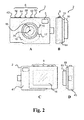
- the camera device comprises a camera housing having a first surface (front) and a second surface (back). Furthermore, the camera housing has a top surface and a bottom surface. The first surface (front) of the camera housing is facing towards a target object and the second surface (back) of the camera housing is facing away from the target object.
- the camera device comprises a sensor arrangement.
- the sensor arrangement may comprise one or more image sensors, such as a CCD image sensor, a CMOS image sensor or a sCMOS comprising a CMOS readout integrated circuits (ROICs) bonded to a CCD imaging substrate.
- image sensors such as a CCD image sensor, a CMOS image sensor or a sCMOS comprising a CMOS readout integrated circuits (ROICs) bonded to a CCD imaging substrate.
- ROIICs CMOS readout integrated circuits
- the camera device comprises a lens housing.
- the lens housing may comprise a first lens housing surface with a lens opening.
- a center axis extends through the lens opening, e.g. the center of the lens opening.
- the lens opening admits light rays to pass through the lens opening onto the sensor arrangement.
- the lens housing may comprise an aperture for reducing the amount of admitted light rays onto the sensor arrangement.
- the lens housing may be arranged around the center axis, and the first lens housing surface may be parallel with the first surface of the camera housing.
- the lens housing may be mounted on the first surface of the camera housing or built into the first surface of the camera housing.
- the camera device comprises a flash arrangement.
- the flash arrangement may comprise a plurality of LED elements, wherein the plurality of LED elements may include at least a first LED element configured to emit light with a first intensity profile and a second LED element configured to emit light with a second intensity profile.
- the intensity profile of a LED element may be the intensity level as a function of wavelength or color.
- the plurality of LED elements may emit different colors uniform or non-uniform and different intensity level being uniform or non-uniform.
- the plurality of LED elements may have the same or different intensity profiles.
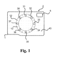
- the flash arrangement may be arranged between the first lens housing surface and the second surface of the camera housing. Additionally, the flash arrangement may be arranged around the center axis and encircling the lens opening. Furthermore, the flash arrangement may be mounted on the first surface of the camera housing or built into the first surface of the camera housing.
- the flash arrangement may have a shape of a ring, a regular or a non-regular polygon.
- the plurality of LED elements may comprise at least four, five, six or more LED elements including a first LED element, a second LED element, a third LED element, a fourth LED element, optionally a fifth LED element, and optionally a sixth LED element.
- the LED elements may be arranged in an LED plane perpendicular to the center axis.
- the plurality of LED elements may be arranged around the center axis and encircling the lens opening.
- the plurality of LED elements may be arranged at the same or different distances from the center axis, where R 1 , R 2 , R 3 ...., R N denotes the distance and N is the number of LED elements.
- the angle ⁇ ⁇ , j between i'th LED element and j'th LED element is the angle between two axes in the LED plane and crossing the center axis and the respective LED elements or projections thereof into the LED plane.
- the LED elements may be evenly distributed around the center axis and around the lens opening.
- ⁇ 1 , 2 may be in the range from 30° to 90°, such as from 40° to 60°.
- An LED element may include one or a plurality of LEDs.
- the camera device comprises at least one diffuser optionally mounted on or in the camera housing.
- the diffuser is configured to spread or diffuse emitted light from the plurality of LED elements, e.g. for obtaining improved flash light distribution or properties.
- the diffuser has an inner diffuser edge and an outer diffuser edge, wherein the inner and/or outer diffuser edges may have the shape of a ring, oval, a non-regular or a regular polygon.
- the diffuser may have a first diffuser surface facing a target object.
- the first diffuser surface may be plane or substantially plane and may be perpendicular to the center axis.
- the diffuser may have a second diffuser surface facing the plurality of LED elements.
- the inner diffuser edge may surround or encircle the lens opening and the center axis and thus form a diffuser opening for image capture through the diffuser opening.
- the diffuser may be divided into a number of diffuser segments, e.g. corresponding to the number of LED elements.
- the diffuser segments may be ring segments of a ring diffuser.
- a light blocking layer may be arranged between two neighboring diffuser segments.
- the diffuser may be mounted between an image object and the plurality of LED elements for diffusing light from the LED elements towards the image object.
- the diffuser may be mounted on the first surface of the camera housing or built into the camera housing.
- the diffuser may be arranged around the center axis and encircling the lens opening, and the diffuser may cover the plurality of LED elements.
- the inner diffuser edge may be circular and having an inner radius R d1 .
- the outer diffuser edge may be circular and having an outer diffuser radius R d2 larger than the inner radius for forming a ring shaped diffuser is formed.
- the inner diffuser radius may be uniform or non-uniform in the range from 1 mm to 40 mm, such as from 2 mm to 25 mm.
- the outer diffuser radius is larger than the inner diffuser radius and may be uniform or non-uniform in the range from 2 mm to 50 mm, such as from 5 mm to 20 mm.
- the outer diffuser radius may be larger than 3 mm.
- the outer diffuser radius may be less than 30 mm. In a currently preferred camera device, the outer diffuser radius is in the range from 5 mm to 15 mm.
- the camera housing has pocket size.
- the camera housing may have a length (distance from first side to second side) less than 150 mm such as in the range from 30 to 100 mm.
- the camera housing may have a height (distance from top to bottom) less than 100 mm such as in the range from 30 mm to 80 mm.
- the camera housing may have a thickness (distance from first to second surface) less than 40 mm or less than 30 mm.
- the diffuser may be made of any suitable diffuser material, such as a polymer or a polymer composition comprising a mix of polymers optionally with one or more additives.
- a suitable diffuser material may be polyethylene (PET), polyvinylchloride (PVC) or glass.
- the camera device may comprise a lens arrangement, and the lens arrangement may comprise a lens opening admitting light rays, optionally at least one optical lens for focusing admitted light rays and an aperture.
- the lens arrangement may comprise a first lens surface facing an image object.
- the lens arrangement may be mounted on the first surface of the camera housing or built into the first surface of the camera housing. The lens arrangement may be aligned with the sensor arrangement.
- the lens arrangement or the lens housing may comprise a focus adjustment element for manual adjustment of the camera lens focal of the lens arrangement.
- the focus adjustment element may be mounted on the lens arrangement or on the lens housing.
- the camera device comprises a user interface configured for receiving user input.
- the user interface may comprise one or more buttons, e.g. including a first button and/or a second button.
- the user interface may comprise a third button and/or a fourth button.
- the user interface may comprise a slider or other selector device having a plurality of positions including a first and second position.
- the slider may be at least two -position slider, i.e. a slider with at least a first position and a second position.
- the slider may be used for setting operating parameters or operation mode of the flash arrangement.
- the camera device may comprise a wireless communication unit, e.g. including a 3G module and/or a WIFI module.
- the wireless communication unit may be configured to upload a recorded picture or image to a server at a selected provider for upload to a social network or other image network, such as Facebook, Instagram, Dailybooth, Flickr, Fotki, Fotolog, My Opera or Twitter.
- the configuration of at least one preselected social network may be performed by the user or the distributor of the camera device.
- the wireless communication unit may upload the recorded picture to a cloud computing network, the cloud computing network being Client-server software on a remote station.
- the Client-server may be a web-server for storing personal information, such as pictures.
- the camera device may comprise one or more of a memory unit for storing the recorded picture locally, a SIM card slot, a battery compartment for accommodation of a battery or other power source, and a connection interface, e.g. for transferring data between the camera device and an external unit and/or charging a battery or other power source.
- the connection interface may include a mini USB interface
- the camera device may comprise a view display for live view functionality and/or for displaying a recorded picture or parts thereof.
- the view display may be a CCD display or other display known for cameras.
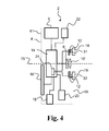
- the camera device comprises a controller unit connected to the user interface, the sensor arrangement and the flash arrangement.
- the controller unit may comprise a flash controller.
- the controller unit/flash controller controls the flash arrangement according to one or more operating schemes which may be selected from a plurality of operating schemes. An operating scheme may control the first LED element and the second LED element individually and/or simultaneously.
- the camera device may comprise a viewfinder shaped as an opening from the first surface to the second surface of the camera housing.
- the viewfinder may have a rectangular cross section.
- the viewfinder may be used by the user for composing a picture of the target object. The user looks through the viewfinder and what the user sees provides at least an indication of what is recorded by the camera device.
Landscapes
- Engineering & Computer Science (AREA)
- Multimedia (AREA)
- Signal Processing (AREA)
- Studio Devices (AREA)
- Stroboscope Apparatuses (AREA)
Priority Applications (2)
| Application Number | Priority Date | Filing Date | Title |
|---|---|---|---|
| EP13172064.1A EP2814235A1 (de) | 2013-06-14 | 2013-06-14 | Kameravorrichtung mit Diffusor und entsprechendes Verfahren |
| PCT/EP2014/062568 WO2014198961A1 (en) | 2013-06-14 | 2014-06-16 | Camera device with diffuser and related method |
Applications Claiming Priority (1)
| Application Number | Priority Date | Filing Date | Title |
|---|---|---|---|
| EP13172064.1A EP2814235A1 (de) | 2013-06-14 | 2013-06-14 | Kameravorrichtung mit Diffusor und entsprechendes Verfahren |
Publications (1)
| Publication Number | Publication Date |
|---|---|
| EP2814235A1 true EP2814235A1 (de) | 2014-12-17 |
Family
ID=48625879
Family Applications (1)
| Application Number | Title | Priority Date | Filing Date |
|---|---|---|---|
| EP13172064.1A Withdrawn EP2814235A1 (de) | 2013-06-14 | 2013-06-14 | Kameravorrichtung mit Diffusor und entsprechendes Verfahren |
Country Status (2)
| Country | Link |
|---|---|
| EP (1) | EP2814235A1 (de) |
| WO (1) | WO2014198961A1 (de) |
Cited By (3)
| Publication number | Priority date | Publication date | Assignee | Title |
|---|---|---|---|---|
| CN107734226A (zh) * | 2017-10-24 | 2018-02-23 | 捷开通讯(深圳)有限公司 | 用于电子设备的拍摄装置及电子设备 |
| CN105938288B (zh) * | 2016-01-16 | 2018-08-03 | 深圳市宗匠科技有限公司 | 一种补光灯 |
| WO2024164662A1 (zh) * | 2023-02-06 | 2024-08-15 | 荣耀终端有限公司 | 电子设备 |
Families Citing this family (1)
| Publication number | Priority date | Publication date | Assignee | Title |
|---|---|---|---|---|
| JP6512979B2 (ja) * | 2015-07-23 | 2019-05-15 | キヤノン株式会社 | 撮像装置 |
Citations (7)
| Publication number | Priority date | Publication date | Assignee | Title |
|---|---|---|---|---|
| WO1993017397A1 (en) * | 1992-02-27 | 1993-09-02 | Alex Roustaei | Optical scanning head |
| US5313373A (en) * | 1992-11-25 | 1994-05-17 | United Parcel Service Of America, Inc. | Apparatus for the uniform illumination of a surface |
| US5818528A (en) * | 1994-10-25 | 1998-10-06 | United Parcel Service Of America | Automatic electronic camera for label image capture |
| US20050030416A1 (en) * | 2003-08-04 | 2005-02-10 | Eiji Kametani | Image capturing device |
| US20060133061A1 (en) * | 2004-11-30 | 2006-06-22 | Fuji Photo Film Co. Ltd | Image taking apparatus with flash device |
| EP1830306A2 (de) * | 2006-03-03 | 2007-09-05 | Fujitsu Ltd. | Bilderfassungsvorrichtung mit Distanzmessfunktion |
| US8363157B1 (en) * | 2010-12-15 | 2013-01-29 | Google Inc. | Mobile communication device with multiple flashpoints |
Family Cites Families (1)
| Publication number | Priority date | Publication date | Assignee | Title |
|---|---|---|---|---|
| WO2005071372A1 (ja) * | 2004-01-23 | 2005-08-04 | Olympus Corporation | 画像処理システム、カメラ |
-
2013
- 2013-06-14 EP EP13172064.1A patent/EP2814235A1/de not_active Withdrawn
-
2014
- 2014-06-16 WO PCT/EP2014/062568 patent/WO2014198961A1/en not_active Ceased
Patent Citations (7)
| Publication number | Priority date | Publication date | Assignee | Title |
|---|---|---|---|---|
| WO1993017397A1 (en) * | 1992-02-27 | 1993-09-02 | Alex Roustaei | Optical scanning head |
| US5313373A (en) * | 1992-11-25 | 1994-05-17 | United Parcel Service Of America, Inc. | Apparatus for the uniform illumination of a surface |
| US5818528A (en) * | 1994-10-25 | 1998-10-06 | United Parcel Service Of America | Automatic electronic camera for label image capture |
| US20050030416A1 (en) * | 2003-08-04 | 2005-02-10 | Eiji Kametani | Image capturing device |
| US20060133061A1 (en) * | 2004-11-30 | 2006-06-22 | Fuji Photo Film Co. Ltd | Image taking apparatus with flash device |
| EP1830306A2 (de) * | 2006-03-03 | 2007-09-05 | Fujitsu Ltd. | Bilderfassungsvorrichtung mit Distanzmessfunktion |
| US8363157B1 (en) * | 2010-12-15 | 2013-01-29 | Google Inc. | Mobile communication device with multiple flashpoints |
Cited By (5)
| Publication number | Priority date | Publication date | Assignee | Title |
|---|---|---|---|---|
| CN105938288B (zh) * | 2016-01-16 | 2018-08-03 | 深圳市宗匠科技有限公司 | 一种补光灯 |
| CN107734226A (zh) * | 2017-10-24 | 2018-02-23 | 捷开通讯(深圳)有限公司 | 用于电子设备的拍摄装置及电子设备 |
| WO2019080869A1 (zh) * | 2017-10-24 | 2019-05-02 | 捷开通讯(深圳)有限公司 | 用于电子设备的拍摄装置及电子设备 |
| US11131902B2 (en) | 2017-10-24 | 2021-09-28 | JRD Communication (Shenzhen) Ltd. | Electronic device and capturing apparatus for electronic device |
| WO2024164662A1 (zh) * | 2023-02-06 | 2024-08-15 | 荣耀终端有限公司 | 电子设备 |
Also Published As
| Publication number | Publication date |
|---|---|
| WO2014198961A1 (en) | 2014-12-18 |
Similar Documents
| Publication | Publication Date | Title |
|---|---|---|
| CN105580348B (zh) | 摄像装置及摄像方法 | |
| US9544503B2 (en) | Exposure control methods and apparatus | |
| CN107113415B (zh) | 用于多技术深度图获取和融合的方法和设备 | |
| US9521321B1 (en) | Enabling manually triggered multiple field of view image capture within a surround image mode for multi-lens mobile devices | |
| US9953428B2 (en) | Digital camera unit with simultaneous structured and unstructured illumination | |
| CN105191285A (zh) | 固体摄像器件、电子装置、镜头控制方法和摄像模块 | |
| US20150222868A1 (en) | White-balance color temperature measuring device for image pick-up device | |
| US11405539B2 (en) | Background replacement system and methods | |
| CN103780840A (zh) | 一种高品质成像的双摄像成像装置及其方法 | |
| WO2017069906A1 (en) | Camera assembly with filter providing different effective entrance pupil sizes based on light type | |
| CN102629068B (zh) | 拍摄设备、显示控制方法 | |
| CN104717482A (zh) | 多光谱多景深阵列拍摄方法与拍摄相机 | |
| US9407845B1 (en) | Self powering camera | |
| CN102629973B (zh) | 摄像装置和摄像方法 | |
| WO2014198961A1 (en) | Camera device with diffuser and related method | |
| JP2014137482A (ja) | 撮影装置および撮影用照明装置 | |
| US10642128B2 (en) | Edge light device for photography system | |
| TWI446089B (zh) | 鏡頭擴充座 | |
| CN204669468U (zh) | 移动终端 | |
| JP2009176471A (ja) | Led光源用レンズ | |
| EP3522528B1 (de) | Bild mit abgleichskorrekturverfahren und elektronische vorrichtung | |
| CN104092954A (zh) | 闪光控制方法及控制装置、图像采集方法及采集装置 | |
| CN206023906U (zh) | 一种智能手机及其光线感应传感器 | |
| CN119562157A (zh) | 水下拍摄方法、装置及电子设备 | |
| CN207505000U (zh) | 一种摄像模组、装置及移动设备 |
Legal Events
| Date | Code | Title | Description |
|---|---|---|---|
| 17P | Request for examination filed |
Effective date: 20130614 |
|
| AK | Designated contracting states |
Kind code of ref document: A1 Designated state(s): AL AT BE BG CH CY CZ DE DK EE ES FI FR GB GR HR HU IE IS IT LI LT LU LV MC MK MT NL NO PL PT RO RS SE SI SK SM TR |
|
| AX | Request for extension of the european patent |
Extension state: BA ME |
|
| PUAI | Public reference made under article 153(3) epc to a published international application that has entered the european phase |
Free format text: ORIGINAL CODE: 0009012 |
|
| STAA | Information on the status of an ep patent application or granted ep patent |
Free format text: STATUS: THE APPLICATION IS DEEMED TO BE WITHDRAWN |
|
| 18D | Application deemed to be withdrawn |
Effective date: 20150618 |