EP2814302A1 - Module d'éclairage et système d'éclairage correspondant - Google Patents
Module d'éclairage et système d'éclairage correspondant Download PDFInfo
- Publication number
- EP2814302A1 EP2814302A1 EP14170495.7A EP14170495A EP2814302A1 EP 2814302 A1 EP2814302 A1 EP 2814302A1 EP 14170495 A EP14170495 A EP 14170495A EP 2814302 A1 EP2814302 A1 EP 2814302A1
- Authority
- EP
- European Patent Office
- Prior art keywords
- lighting
- lighting module
- voltage
- terminal
- identification element
- Prior art date
- Legal status (The legal status is an assumption and is not a legal conclusion. Google has not performed a legal analysis and makes no representation as to the accuracy of the status listed.)
- Withdrawn
Links
- 238000005259 measurement Methods 0.000 claims description 17
- 238000013021 overheating Methods 0.000 description 8
- 239000000463 material Substances 0.000 description 2
- 230000003213 activating effect Effects 0.000 description 1
- 238000010276 construction Methods 0.000 description 1
- 230000005669 field effect Effects 0.000 description 1
- 238000010438 heat treatment Methods 0.000 description 1
- 229910044991 metal oxide Inorganic materials 0.000 description 1
- 150000004706 metal oxides Chemical class 0.000 description 1
- 238000000034 method Methods 0.000 description 1
- 239000004065 semiconductor Substances 0.000 description 1
- 238000010792 warming Methods 0.000 description 1
Images


Classifications
-
- H—ELECTRICITY
- H05—ELECTRIC TECHNIQUES NOT OTHERWISE PROVIDED FOR
- H05B—ELECTRIC HEATING; ELECTRIC LIGHT SOURCES NOT OTHERWISE PROVIDED FOR; CIRCUIT ARRANGEMENTS FOR ELECTRIC LIGHT SOURCES, IN GENERAL
- H05B45/00—Circuit arrangements for operating light-emitting diodes [LED]
- H05B45/10—Controlling the intensity of the light
-
- H—ELECTRICITY
- H05—ELECTRIC TECHNIQUES NOT OTHERWISE PROVIDED FOR
- H05B—ELECTRIC HEATING; ELECTRIC LIGHT SOURCES NOT OTHERWISE PROVIDED FOR; CIRCUIT ARRANGEMENTS FOR ELECTRIC LIGHT SOURCES, IN GENERAL
- H05B45/00—Circuit arrangements for operating light-emitting diodes [LED]
- H05B45/50—Circuit arrangements for operating light-emitting diodes [LED] responsive to malfunctions or undesirable behaviour of LEDs; responsive to LED life; Protective circuits
- H05B45/56—Circuit arrangements for operating light-emitting diodes [LED] responsive to malfunctions or undesirable behaviour of LEDs; responsive to LED life; Protective circuits involving measures to prevent abnormal temperature of the LEDs
-
- H—ELECTRICITY
- H05—ELECTRIC TECHNIQUES NOT OTHERWISE PROVIDED FOR
- H05B—ELECTRIC HEATING; ELECTRIC LIGHT SOURCES NOT OTHERWISE PROVIDED FOR; CIRCUIT ARRANGEMENTS FOR ELECTRIC LIGHT SOURCES, IN GENERAL
- H05B45/00—Circuit arrangements for operating light-emitting diodes [LED]
- H05B45/10—Controlling the intensity of the light
- H05B45/12—Controlling the intensity of the light using optical feedback
-
- H—ELECTRICITY
- H05—ELECTRIC TECHNIQUES NOT OTHERWISE PROVIDED FOR
- H05B—ELECTRIC HEATING; ELECTRIC LIGHT SOURCES NOT OTHERWISE PROVIDED FOR; CIRCUIT ARRANGEMENTS FOR ELECTRIC LIGHT SOURCES, IN GENERAL
- H05B45/00—Circuit arrangements for operating light-emitting diodes [LED]
- H05B45/10—Controlling the intensity of the light
- H05B45/18—Controlling the intensity of the light using temperature feedback
Definitions
- the description relates to lighting systems.
- Electronic converters for light sources that comprise, for example, at least one LED (Light-Emitting Diode) or other solid-state lighting means, can supply at output a d.c. current.
- Said current may be stable or even vary in time, for example, for adjusting the intensity of the light emitted by the light source (the so-called "dimming function").
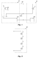
- Figure 1 shows a possible lighting system including an electronic converter 10 and a lighting module 20 comprising, for example, at least one LED L.
- Figure 2 shows an example of a lighting module 20 that comprises a LED string, i.e., a plurality of LEDs connected in series. For instance, in Figure 2 four LEDs L 1 , L 2 , L 3 and L 4 are shown.
- the electronic converter 10 usually comprises a control circuit 102 and a power circuit 12 (for example, an AC/DC or DC/DC switching supply), which receives at input a voltage or generally a supply signal (for example, from the electric power line) and supplies at output, via a power output 106, a d.c. current.
- a power output 106 comprises two power supply terminals or lines, wherein the negative terminal represents a ground GND. This current may be stable or even vary over time.
- the control circuit 102 can set, via a reference channel I ref of the power circuit 12, the current required by the LED module 20.
- this reference channel I ref may be used for adjusting the intensity of the light emitted by the lighting module 20.
- an adjustment of the intensity of light emitted by the LED module 20 can be made by adjusting the average current that traverses the lighting module, for example by setting a lower reference current I ref or activating or de-activating the power circuit 12 through a signal with a pulse-width modulation (PWM).
- PWM pulse-width modulation
- the LED module 20 may also comprise an identification element 202 that identifies the current required by the lighting module 20 (or in general control parameters).
- the control circuit 102 communicates with the identification element 202 and adapts operation of the electronic converter 10.
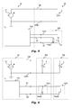
- Figure 3 illustrates an embodiment in which the identification element 202 comprises a simple resistor Rset.
- the control unit 102 can measure the resistance of the resistor Rset and adapt operation of the power circuit 12 as a function of the resistance detected.
- the resistor Rset is connected to the control unit 102 by means of two terminals or lines S1 and S2.
- the line S2 is connected to ground GND and consequently could be also provided only the measuring line S1.
- the control unit 102 comprises a pull-up resistor R1 connected in series with the resistor Rset.
- the voltage divider comprising the resistors R1 and Rset, can be supplied via a voltage Vcc, and the voltage Vset at the intermediate point between the resistors R1 and Rset, i.e., on the line S1, identifies the resistance of the resistor Rset.
- Figure 4 shows an example where the resistor Rset is directly supplied through a current generator that generates a reference current Iset.
- the identification element 202 may also comprise a temperature sensor. For instance, this may be useful for varying the supply current on the line 106 as a function of the temperature of the lighting module 20 and/or for deactivating supply in the event of overheating of the lighting module 20.
- Figure 5 shows an identification element 202 that comprises both a resistor Rset for setting the nominal current and a temperature sensor TS, such as for example a thermistor of the negative-temperature-coefficient (NTC) type.
- a temperature sensor TS such as for example a thermistor of the negative-temperature-coefficient (NTC) type.
- NTC thermistor is connected between an auxiliary line AUX and the line S2, and the resistance of the NTC thermistor can be measured as the resistance of the resistor Rset.
- the value of the resistance between the measuring lines S1 and S2 could be varied also directly as a function of the temperature of the lighting module 20. Consequently, in general, the resistance of the resistor Rset or the resistance between the lines S1 and S2 is not necessarily fixed, but could also vary during operation.
- Figure 6 shows an example in which two lighting modules 20a and 20b are connected in parallel between the line 106 and ground GND.
- the respective identification elements 202a and 202b can be connected in parallel. In this way, the resistance detected between the lines S1 and S2 always identifies the global current required by the lighting modules 20, i.e., the sum of the current required by the module 20a and the current required by the module 20b.
- Figure 7 shows an example in which two lighting modules 20a and 20b are connected in series between the line 106 and ground GND.
- the inventors have noted that in this case the current supplied by the electronic converter 12 should be set at the minimum value required by one of the lighting modules 20a and 20b. However, this cannot be obtained either with a connection in series or with a connection in parallel of the identification elements 202a and 202b when these are resistors.
- the object of the invention is to overcome the drawbacks outlined above.
- the above object is achieved thanks to a lighting module having the characteristics recalled in the ensuing claims.
- the claims also regard a corresponding lighting system.
- setting of the current may be made by means of a regulator, such as a shunt-regulator, frequently also referred to as “regulator of the parallel type", or a Zener diode.
- a regulator such as a shunt-regulator, frequently also referred to as “regulator of the parallel type", or a Zener diode.
- the lighting module comprises at least one light source, such as for example a LED or a LED string, and an identification element that identifies at least the supply current required by the light source.
- the identification element comprises a first terminal and a second terminal for connection to an electronic converter, e.g. via respective measurement lines.
- the identification element comprises at least one regulator, such as for example a shunt regulator or a Zener diode, configured for limiting the voltage across the two terminals to a maximum threshold voltage that identifies the supply current required by the light sources.
- a regulator such as for example a shunt regulator or a Zener diode, configured for limiting the voltage across the two terminals to a maximum threshold voltage that identifies the supply current required by the light sources.
- the identification element comprises a regulator, such as a shunt regulator, configured for varying its maximum threshold voltage, for example, as a function of the temperature of the lighting module and/or of the light source.
- a regulator such as a shunt regulator
- the identification element comprises a first regulator, e.g. a first shunt regulator, with a maximum threshold voltage that identifies the nominal current required by the light source, and a second regulator, e.g. a second shunt regulator, configured for varying its maximum threshold voltage, for example, as a function of the temperature of the lighting module and/or of the light sources.
- the shunt regulators are in this case connected in parallel. Consequently, the second shunt regulator can reduce the voltage across the two terminals when the lighting module and/or the light sources are warming up.
- the identification element comprises an electronic switch that shortcircuits the two terminals when the temperature of the lighting module and/or of the light sources exceeds a temperature threshold.
- the electronic converter comprises a power circuit for supplying the light source of the lighting module and a control circuit that detects the voltage across the two terminals of the identification element and sets the output current of the power circuit in such a way that the current supplied varies as a function of the voltage detected.
- the electronic converter comprises at least:
- the control circuit sets the output current of the power circuit in such a way that the current supplied corresponds to the current identified through the voltage across the two terminals.
- the control circuit could also deactivate the current supplied by the power circuit when the voltage detected has untypical values, for example when the voltage detected is lower than a first threshold (typical for an overheating or some other malfunctioning of the lighting module) and/or higher than a second threshold (which is typical of the case where no lighting module is connected to the power supply).
- the electronic converter supplies a current via the power supply lines that corresponds to the minimum current required.
- Figure 8 illustrates an embodiment of an identification element according to the present description.
- the light sources L of the lighting module 20 are connected between the power supply terminals 106 and the identification element 202 is connected, as previously, to the control unit 102 through two lines S1 and S2.
- the relative description concerning the technological background will not be repeated, and the same reference signs will be used for identical or functional similar or equivalent components.
- the electronic converter 10 and the lighting module 20 comprise at least:
- Zener diode Z where the threshold voltage of the Zener diode Z identifies the current required by the lighting module 20, i.e. the current required by the light sources L.
- any other regulator such as a shunt regulator, that enables limitation of the voltage across the terminals S1 and S2 to a given maximum threshold voltage could be used.
- a shunt regulator an integrated circuit of the LM431 type is used as shunt regulator.
- control unit 102 comprises means for detecting the threshold voltage of the Zener diode Z.
- any of the control circuits described with respect to Figures 3 and 4 could be used for this purpose.
- the line S1 is connected through a pull-up resistor R1 to a constant voltage Vcc. Consequently, when no identification element 202 is connected between the lines S1 and S2, the voltage across the lines S1 and S2 substantially corresponds to Vcc.
- the value of the voltage Vcc basically identifies the maximum current that the power circuit 12 is able to supply.
- the voltage Vcc could even be higher, for example, to verify the presence of a lighting module compatible with the converter 10.
- the power output 106 could be deactivated.
- this threshold could correspond to the maximum current that the power circuit 12 is able to supply.
- the identification element 202 when the identification element 202 is connected between the lines S1 and S2, the identification element 202, i.e., the Zener diode Z, sets on the line S1 a voltage that corresponds to the threshold voltage of the Zener diode Z. For instance, the higher is the threshold voltage of the Zener diode Z, the higher is the supply current required by the respective lighting module 20.
- control unit 102 can detect the voltage on the line S1, i.e., the threshold voltage of the Zener diode Z, and set the power circuit 12 in such a way that the current supplied on the line 106 corresponds to the current required.
- the identification element 202 can be used when a plurality of lighting modules 20 is connected in series, i.e. when the light souces L of the various lighting modules 20 are connected in series between the power supply terminals 106 of the electronic converter 10.
- the identification elements 202 of the respective lighting modules 20 are connected for this purpose in parallel; i.e., the identification elements 202 are connected in parallel between the measurement terminals S1 and S2 of the electronic converter 10 and the voltage across the lines S1 and S2 is set at the lower threshold voltage.
- Figure 9 illustrates an embodiment in which two lighting modules 20a and 20b are connected in series, i.e. the respective light sources are connected in series between the power supply lines 106.
- the respective Zener diodes Za and Zb are connected in parallel, and the voltage on the line S1 corresponds (at the most) to the threshold voltage of the diodes Za and Zb that is lower.
- the Zener diode Za could have a threshold voltage of 2.8 V and the Zener diode Zb could have a threshold voltage of 1.4 V. Consequently, in the case where the voltage Vcc is higher than 1.4 V, the Zener diode Zb would limit the voltage on the line S1 to 1.4 V.
- control circuit 102 once the voltage Vset of 1.4 V has been detected, would set the power circuit 12, e.g. via the current reference signal Iref, in such a way that a current of 1 A is supplied through the power output 106.
- the identification element 202 may comprise a temperature sensor. For instance, this may be useful for varying the supply current on the line 106 as a function of the temperature of the lighting module 20 that requires the minimum supply current or for deactivating the supply in the event of overheating of one of the lighting modules 20.
- this can be obtained by varying the threshold voltage of the lighting module 20, i.e. the threshold voltage of the respective identification element 202.
- Figure 10 illustrates an embodiment, where, instead of the Zener diode Z with constant threshold voltage, a shunt regulator 204 is used, where the threshold voltage of the shunt regulator 204 is set through a temperature sensor TS, such as for example a thermistor of the NTC or PTC type.
- a temperature sensor TS such as for example a thermistor of the NTC or PTC type.
- the identification element 202 could also comprise a Zener diode Z connected in series or preferably in parallel with a shunt regulator 204 (or two shunt regulators connected in parallel).
- the Zener diode Z (or the first shunt regulator) could indicate the nominal current required, and the shunt regulator 204 (or the second shunt regulator) could only intervene when a compensation of heating of the lighting module 20 is necessary.
- the variation of the current set point i.e., of the voltage across the identification element 202
- the variation of the current set point can depend also upon other factors.
- a temperature sensor instead of a temperature sensor other sensors may also be used, such as:
- a plurality of sensors for example each connected to a respective shunt regulator, can be used together.
- the solutions described herein may also be used for deactivating the output current of the power circuit 12, e.g. in the event of overheating of one of the lighting modules.
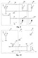
- Figure 11 illustrates an embodiment with overheating protection.
- the identification element 202 comprises a Zener diode Z, where the threshold voltage identifies the nominal current required.
- a protection circuit 206 is connected in parallel to the Zener diode Z.
- this protection circuit 206 is configured for limiting the voltage across the terminals S1 and S2 in response to a signal from at least one sensor.
- the protection circuit 206 is configured for limiting the voltage across the terminals S1 and S2 to a given voltage when the temperature of the respective lighting module exceeds a given threshold. In particular, this given voltage should be lower than the threshold voltages that are used by the Zener diodes Z that set the respective nominal currents.
- this protection circuit 206 could be a shunt regulator.
- a complicate shunt regulator with variable threshold voltage is not necessary, but a simple electronic switch is sufficient, such as for example a MOSFET (Metal Oxide Semiconductor Field Effect Transistor), which shortcircuits the lines S1 and S2; namely, the voltage threshold that indicates an overheating corresponds to a voltage Vset of 0 V. Consequently, when the control circuit 102 detects a voltage Vset of 0 V, the control circuit 102 could deactivate the power output 106.
- MOSFET Metal Oxide Semiconductor Field Effect Transistor
- the protection circuit 106 comprises an electronic switch SW, such as a MOSFET, which is driven via a comparator that compares the temperature of the lighting module with a reference temperature, in which:
- the operational amplifier U1 and the voltage dividers (R1 and R4, R2 and TS) are supplied through a constant voltage.
- Said voltage can be received from the electronic converter 10, for example via a line AUX (see Figure 11 ), or can be generated within the lighting module 20, for example by the current supplied on the line 106.
- Figure 12 shows a second possible embodiment of a protection circuit 206, where a BJT (Bipolar Junction Transistor) is used as electronic switch.
- BJT Bipolar Junction Transistor
- the base of the transistor SW is connected to the intermediate point of a voltage divider once again made up of a temperature sensor TS, such as an NTC thermistor, and a resistor R2. Also in this case, the voltage divider is supplied via a reference voltage, which, as before, may be supplied, for example, by the control unit 102.
- the NTC thermistor forms part of the lower branch of the voltage divider, i.e., is connected to ground
- the NTC thermistor forms part of the upper branch of the voltage divider; i.e., it is connected to the reference voltage.
- the above embodiments may also be used with other sensors, such as twilight sensors or presence sensors.
- the solutions described herein enable connection of a plurality of lighting modules in series.
- the supply current corresponds to the lower nominal current.
- the solutions may also be used in combination with other sensors, for example to obtain a temperature compensation and/or an overheating protection.
- the converter 10 is connected to the lighting modules 20 usually via at least four terminals comprising the two power supply terminals 106 and the two measurement terminals S1 and S2.
- the two measurement terminals S1 and S2 are connected to the converter 10.
- the second measurement line S2 could be connected to ground GND.
- solutions described herein may also be used for solving the connection in parallel of the LED strings.
- Figure 13 shows a possible embodiment of a lighting system, where a plurality of lighting modules 20, for example two modules 20a and 20b, are connected in parallel; i.e., the light sources L, such as for example LED strings, are connected in parallel, i.e. the light sources L are connected in parallel between the power supply terminals 106 of the electronic converter 10.
- the light sources L such as for example LED strings
- the respective identification elements 202 of the lighting modules 20 are connected in series, i.e., the respective voltage references 202, for example the Zener diodes Za and Zb or the equivalent shunt regulator, are connected in series, i.e. the identification elements 202 are connected in series between the measurement terminals S1 and S2 of the electronic converter 10.
- each identification element 202 can identify the supply current required by the respective lighting module 20. Consequently, the currents required by the various lighting modules 20 are added, and the current generator 12 supplies a current that is equal to the sum of the individual currents required.
Landscapes
- Circuit Arrangement For Electric Light Sources In General (AREA)
Applications Claiming Priority (1)
| Application Number | Priority Date | Filing Date | Title |
|---|---|---|---|
| ITTO20130475 | 2013-06-10 |
Publications (1)
| Publication Number | Publication Date |
|---|---|
| EP2814302A1 true EP2814302A1 (fr) | 2014-12-17 |
Family
ID=49000581
Family Applications (1)
| Application Number | Title | Priority Date | Filing Date |
|---|---|---|---|
| EP14170495.7A Withdrawn EP2814302A1 (fr) | 2013-06-10 | 2014-05-29 | Module d'éclairage et système d'éclairage correspondant |
Country Status (3)
| Country | Link |
|---|---|
| US (1) | US9398658B2 (fr) |
| EP (1) | EP2814302A1 (fr) |
| CN (1) | CN104244510A (fr) |
Cited By (7)
| Publication number | Priority date | Publication date | Assignee | Title |
|---|---|---|---|---|
| DE202015102078U1 (de) * | 2015-04-27 | 2016-08-01 | Zumtobel Lighting Gmbh | Anordnung zur Beleuchtung |
| DE102015112058A1 (de) * | 2015-07-23 | 2017-01-26 | Itz Innovations- Und Technologiezentrum Gmbh | Modul und Betriebsgerät zum Versorgen eines LED-Leuchtmittels mit dazu passend einstellbarem Betriebsstrom |
| EP3139483A1 (fr) | 2015-07-15 | 2017-03-08 | OSRAM GmbH | Convertisseur abaisseur de tension inverse électronique et procédé correspondant de fonctionnement d'un convertisseur abaisseur de tension inverse électronique |
| CN107432072A (zh) * | 2015-02-20 | 2017-12-01 | 豪倍公司 | 发光二极管热返送控制装置及方法 |
| WO2018019596A1 (fr) | 2016-07-29 | 2018-02-01 | Philips Lighting Holding B.V. | Lampe(s) à diodes électroluminescentes avec pilote de canal unique |
| CN109565915A (zh) * | 2016-07-29 | 2019-04-02 | 飞利浦照明控股有限公司 | 具有单通道驱动器的(多个)led灯 |
| DE102017126044A1 (de) * | 2017-11-08 | 2019-05-09 | HELLA GmbH & Co. KGaA | Schaltungsanordnung einer Leuchteinheit eines Scheinwerfers für ein Fahrzeug |
Families Citing this family (9)
| Publication number | Priority date | Publication date | Assignee | Title |
|---|---|---|---|---|
| US9859951B2 (en) * | 2013-11-26 | 2018-01-02 | Linear Technology Corporation | Power over data lines detection and classification scheme |
| CN105792408B (zh) * | 2015-01-09 | 2019-02-15 | 松下知识产权经营株式会社 | 照明系统以及照明器具 |
| JP6489523B2 (ja) * | 2015-03-12 | 2019-03-27 | パナソニックIpマネジメント株式会社 | 固体発光素子モジュールおよび照明セット |
| US20170181240A1 (en) * | 2015-12-16 | 2017-06-22 | General Electric Company | High voltage resistant transmitting circuit for devices communicating on dali bus |
| JP6617882B2 (ja) * | 2016-04-27 | 2019-12-11 | パナソニックIpマネジメント株式会社 | 照明器具、照明システム及び照明システムの設定方法 |
| FR3085099B1 (fr) * | 2018-06-22 | 2023-06-30 | Valeo Vision | Dispositif de pilotage de l'alimentation electrique de sources lumineuses d'un vehicule automobile en fonction des variations de leurs temperatures |
| WO2021156102A1 (fr) | 2020-02-06 | 2021-08-12 | Signify Holding B.V. | Agencement d'éclairage à détection intégrée telle qu'une détection de lumière |
| KR102941524B1 (ko) * | 2021-08-03 | 2026-03-19 | 현대모비스 주식회사 | 온도 및 증폭된 전류에 기반하여 램프 회로를 제어하는 방법 및 이를 적용한 램프 회로 |
| WO2025261836A1 (fr) * | 2024-06-18 | 2025-12-26 | Signify Holding B.V. | Système d'éclairage pour fournir de la lumière, le système d'éclairage étant agencé pour déterminer le nombre de modules d'éclairage connectés en parallèle, ainsi qu'un procédé correspondant |
Citations (5)
| Publication number | Priority date | Publication date | Assignee | Title |
|---|---|---|---|---|
| WO2001001385A1 (fr) * | 1999-06-29 | 2001-01-04 | Welles Reymond | Circuits a reseau de diodes electroluminescentes alimentes en courant alternatif pour afficheurs d'appareils de signalisation |
| WO2002023956A2 (fr) * | 2000-09-15 | 2002-03-21 | Teledyne Lighting And Display Products, Inc. | Alimentation pour des diodes electroluminescentes |
| EP1517588A1 (fr) * | 2003-09-17 | 2005-03-23 | Moritex Corporation | Procédé et dispositif de connexion d'un phare |
| US20110210675A1 (en) * | 2010-02-28 | 2011-09-01 | Panasonic Electric Works Co., Ltd. | Light source module and lighting apparatus, and illumination apparatus using same |
| EP2432299A1 (fr) * | 2010-09-20 | 2012-03-21 | Grote Industries, Inc. | Source de courant constant de DEL compensé par la température |
-
2014
- 2014-05-29 EP EP14170495.7A patent/EP2814302A1/fr not_active Withdrawn
- 2014-06-09 CN CN201410253040.7A patent/CN104244510A/zh active Pending
- 2014-06-10 US US14/300,270 patent/US9398658B2/en active Active
Patent Citations (5)
| Publication number | Priority date | Publication date | Assignee | Title |
|---|---|---|---|---|
| WO2001001385A1 (fr) * | 1999-06-29 | 2001-01-04 | Welles Reymond | Circuits a reseau de diodes electroluminescentes alimentes en courant alternatif pour afficheurs d'appareils de signalisation |
| WO2002023956A2 (fr) * | 2000-09-15 | 2002-03-21 | Teledyne Lighting And Display Products, Inc. | Alimentation pour des diodes electroluminescentes |
| EP1517588A1 (fr) * | 2003-09-17 | 2005-03-23 | Moritex Corporation | Procédé et dispositif de connexion d'un phare |
| US20110210675A1 (en) * | 2010-02-28 | 2011-09-01 | Panasonic Electric Works Co., Ltd. | Light source module and lighting apparatus, and illumination apparatus using same |
| EP2432299A1 (fr) * | 2010-09-20 | 2012-03-21 | Grote Industries, Inc. | Source de courant constant de DEL compensé par la température |
Cited By (17)
| Publication number | Priority date | Publication date | Assignee | Title |
|---|---|---|---|---|
| CN107432072B (zh) * | 2015-02-20 | 2020-11-24 | 豪倍公司 | 发光二极管热返送控制装置及方法 |
| US10849198B2 (en) | 2015-02-20 | 2020-11-24 | Hubbell Incorporated | Light emitting diode thermal foldback control device and method |
| US11877362B2 (en) | 2015-02-20 | 2024-01-16 | HLI Solutions, Inc. | Light emitting diode thermal foldback control device and method |
| CN107432072A (zh) * | 2015-02-20 | 2017-12-01 | 豪倍公司 | 发光二极管热返送控制装置及方法 |
| CN112333872A (zh) * | 2015-02-20 | 2021-02-05 | 豪倍公司 | 发光二极管热返送控制装置及方法 |
| EP3259961A4 (fr) * | 2015-02-20 | 2018-10-31 | Hubbell Incorporated | Dispositif et procédé de commande de limitation de repli thermique de diode électroluminescente |
| EP3624565A1 (fr) * | 2015-02-20 | 2020-03-18 | Hubbell Incorporated | Dispositif et procédé de commande de régulation thermique de diode électroluminescente |
| US10412804B2 (en) | 2015-02-20 | 2019-09-10 | Hubbell Incorporated | Light emitting diode thermal foldback control device and method |
| AT16808U1 (de) * | 2015-04-27 | 2020-09-15 | Zumtobel Lighting Gmbh | Anordnung zur Beleuchtung |
| DE202015102078U1 (de) * | 2015-04-27 | 2016-08-01 | Zumtobel Lighting Gmbh | Anordnung zur Beleuchtung |
| EP3139483A1 (fr) | 2015-07-15 | 2017-03-08 | OSRAM GmbH | Convertisseur abaisseur de tension inverse électronique et procédé correspondant de fonctionnement d'un convertisseur abaisseur de tension inverse électronique |
| DE102015112058A1 (de) * | 2015-07-23 | 2017-01-26 | Itz Innovations- Und Technologiezentrum Gmbh | Modul und Betriebsgerät zum Versorgen eines LED-Leuchtmittels mit dazu passend einstellbarem Betriebsstrom |
| US10542591B2 (en) | 2016-07-29 | 2020-01-21 | Signify Holding B.V. | LED lamp(s) with single channel driver |
| CN109565915A (zh) * | 2016-07-29 | 2019-04-02 | 飞利浦照明控股有限公司 | 具有单通道驱动器的(多个)led灯 |
| WO2018019596A1 (fr) | 2016-07-29 | 2018-02-01 | Philips Lighting Holding B.V. | Lampe(s) à diodes électroluminescentes avec pilote de canal unique |
| CN109565915B (zh) * | 2016-07-29 | 2021-09-14 | 昕诺飞控股有限公司 | 具有单通道驱动器的led灯 |
| DE102017126044A1 (de) * | 2017-11-08 | 2019-05-09 | HELLA GmbH & Co. KGaA | Schaltungsanordnung einer Leuchteinheit eines Scheinwerfers für ein Fahrzeug |
Also Published As
| Publication number | Publication date |
|---|---|
| CN104244510A (zh) | 2014-12-24 |
| US9398658B2 (en) | 2016-07-19 |
| US20140361693A1 (en) | 2014-12-11 |
Similar Documents
| Publication | Publication Date | Title |
|---|---|---|
| EP2814302A1 (fr) | Module d'éclairage et système d'éclairage correspondant | |
| US7952295B2 (en) | Illuminating device | |
| US9888544B2 (en) | Driving circuits and methods for controlling light source | |
| US7952297B2 (en) | Driving device for providing light dimming control of light-emitting element | |
| US8610368B2 (en) | Serial-type light-emitting diode (LED) device | |
| US8564214B2 (en) | Circuits for sensing current levels within lighting apparatus | |
| US9554440B2 (en) | Dimmable LED lighting apparatus | |
| KR101002600B1 (ko) | 엘이디 조명 제어 회로 | |
| US11246194B2 (en) | Driver circuit with a semiconductor light source and method for operating a driver circuit | |
| US9780875B2 (en) | Visible light communication modulation circuit, illumination device, illumination apparatus and visible light communication system | |
| EP2398298A2 (fr) | Alimentation électrique pour panneau DEL de champ d'avion | |
| KR101517225B1 (ko) | 엘이디 모듈 구동 장치 | |
| US9955540B1 (en) | Low current LED fixture internal auxiliary power supply | |
| EP3095301B1 (fr) | Agencement de circuit pour fonctionnement des chaînes à del | |
| US20120074865A1 (en) | Light emitting diode driving device | |
| CN110870385A (zh) | 照明驱动器、照明电路和驱动方法 | |
| US20140354169A1 (en) | Light emitting diode lighting device | |
| KR20140006200U (ko) | 디밍 제어가 가능한 단방향 엘이디 모듈 장치 | |
| KR20140130333A (ko) | 방송용 led 조명 장치 |
Legal Events
| Date | Code | Title | Description |
|---|---|---|---|
| 17P | Request for examination filed |
Effective date: 20140529 |
|
| AK | Designated contracting states |
Kind code of ref document: A1 Designated state(s): AL AT BE BG CH CY CZ DE DK EE ES FI FR GB GR HR HU IE IS IT LI LT LU LV MC MK MT NL NO PL PT RO RS SE SI SK SM TR |
|
| AX | Request for extension of the european patent |
Extension state: BA ME |
|
| PUAI | Public reference made under article 153(3) epc to a published international application that has entered the european phase |
Free format text: ORIGINAL CODE: 0009012 |
|
| RAP1 | Party data changed (applicant data changed or rights of an application transferred) |
Owner name: OSRAM S.P.A. - SOCIETA' RIUNITE OSRAM EDISON CLERI Owner name: OSRAM GMBH |
|
| R17P | Request for examination filed (corrected) |
Effective date: 20150526 |
|
| RBV | Designated contracting states (corrected) |
Designated state(s): AL AT BE BG CH CY CZ DE DK EE ES FI FR GB GR HR HU IE IS IT LI LT LU LV MC MK MT NL NO PL PT RO RS SE SI SK SM TR |
|
| 17Q | First examination report despatched |
Effective date: 20161004 |
|
| STAA | Information on the status of an ep patent application or granted ep patent |
Free format text: STATUS: THE APPLICATION HAS BEEN WITHDRAWN |
|
| 18W | Application withdrawn |
Effective date: 20161123 |