EP2814357B1 - Procédé de fabrication d'un tiroir - Google Patents
Procédé de fabrication d'un tiroir Download PDFInfo
- Publication number
- EP2814357B1 EP2814357B1 EP13714332.7A EP13714332A EP2814357B1 EP 2814357 B1 EP2814357 B1 EP 2814357B1 EP 13714332 A EP13714332 A EP 13714332A EP 2814357 B1 EP2814357 B1 EP 2814357B1
- Authority
- EP
- European Patent Office
- Prior art keywords
- walls
- board
- profiles
- sidewalls
- groove
- Prior art date
- Legal status (The legal status is an assumption and is not a legal conclusion. Google has not performed a legal analysis and makes no representation as to the accuracy of the status listed.)
- Active
Links
Images



Classifications
-
- B—PERFORMING OPERATIONS; TRANSPORTING
- B27—WORKING OR PRESERVING WOOD OR SIMILAR MATERIAL; NAILING OR STAPLING MACHINES IN GENERAL
- B27F—DOVETAILED WORK; TENONS; SLOTTING MACHINES FOR WOOD OR SIMILAR MATERIAL; NAILING OR STAPLING MACHINES
- B27F4/00—Machines for inserting dowels, with or without drilling equipment
-
- A—HUMAN NECESSITIES
- A47—FURNITURE; DOMESTIC ARTICLES OR APPLIANCES; COFFEE MILLS; SPICE MILLS; SUCTION CLEANERS IN GENERAL
- A47B—TABLES; DESKS; OFFICE FURNITURE; CABINETS; DRAWERS; GENERAL DETAILS OF FURNITURE
- A47B88/00—Drawers for tables, cabinets or like furniture; Guides for drawers
- A47B88/90—Constructional details of drawers
- A47B88/941—Drawers being constructed from two or more parts
-
- B—PERFORMING OPERATIONS; TRANSPORTING
- B27—WORKING OR PRESERVING WOOD OR SIMILAR MATERIAL; NAILING OR STAPLING MACHINES IN GENERAL
- B27F—DOVETAILED WORK; TENONS; SLOTTING MACHINES FOR WOOD OR SIMILAR MATERIAL; NAILING OR STAPLING MACHINES
- B27F1/00—Dovetailed work; Tenons; Making tongues or grooves; Groove- and- tongue jointed work; Finger- joints
- B27F1/08—Making dovetails, tongues, or tenons, of definite limited length
Definitions
- This invention relates to methods for manufacturing drawers, as well as to drawers or drawer constructions which are obtained by means of such method.
- drawers mostly are composed of a plurality of components or walls, such as, for example, a front wall, a rear wall, sidewalls and a bottom.
- Such drawers, or certain parts thereof, are often produced in large quantities by specialized companies, which then distribute these drawers or partial products of drawers to furniture maker.
- small optimizations in the production and assembly of such drawers can result in considerable economic advantages.
- the present invention now relates to methods for manufacturing drawers, as well as well-defined combinations for composing drawers, which allow realizing further optimizations in the production, assembly, respectively, of drawers, which optimizations are of economic and/or technical nature, for example, either by enabling a smoother production or by guaranteeing a more stable construction.
- the invention relates to a method for manufacturing drawers, wherein the drawers comprise walls and a bottom, wherein said walls include at least a front wall, rear wall and two sidewalls, and wherein at least a first and a second of said walls comprise profiles which fit into each other in a locking manner and which to this aim make use of a tongue and a groove with locking parts, wherein said profiles can be joined into each other laterally, and wherein the respective groove is provided on the inner side of the first wall, whereas the respective tongue is provided on the distal end of the second wall, characterized in that two or more walls are manufactured of one board; that herein the profiles of at least two of the respective walls are formed by means of a treatment, whether or not consisting of a plurality of partial treatments, performed on said board; and that said board is divided into two or more walls only after at least parts of said profiles have been formed.
- Such method allows a far-reaching economization in the production process of drawers with locking profiles.
- said treatment is a continuous treatment, wherein the respective board is transported, for example, along one or more, whether or not rotating, cutting tools, wherein said cutting tools engage on the distal ends and/or on the surface of the board in order to form said profiles or parts thereof.
- said transport is performed in the direction or approximately in the direction of the final distal ends.
- the final two walls concerned extend in said board each time with a distal end of one of the walls directed towards the distal end of another wall.
- Dividing the board then preferably is realized at least by performing a cut situated between the directed towards each other distal ends and preferably parallel or almost parallel to the distal ends.
- said board preferably is transported along the tools or cutting tools according to the direction of these distal ends.
- the final two walls concerned extend in said board each time with their distal end in each other's prolongation, or at least with their distal ends parallel to each other.
- Dividing the board then preferably is performed at least by performing a cut situated transverse to the respective parallel distal ends.
- said board preferably is transported along the tools or cutting tools according to the direction of these distal ends.
- said profiles comprise at least a tongue, for example, said tongue of the second wall, which preferably is formed on a distal end of said board. It is not excluded that said tongue might be formed centrally in said board, at the location of a final distal end of a wall, said distal end being obtained after dividing the board. According to a particular embodiment, such tongue can substantially be obtained by means of cutting treatments which engage on only one flat side of said board.
- said profiles comprise at least a groove, for example, said groove of the first wall, which preferably is formed in a flat side of said board.
- At least said first wall and second wall are formed of said one board.
- said board is divided into the first wall and the second wall after at least portions of said profiles have been formed already, namely of said tongue and said groove, whether or not including the locking parts.
- the contour of said tongue as well as of said groove, including the locking parts has been formed already.
- three walls which preferably fit into each other in a locking manner, are obtained from said board, for example, two sidewalls and a front wall, or, according to another example, two sidewalls and a rear wall.
- all locking profiles of the respective walls are formed at least partially or even entirely prior to dividing said board into the three walls concerned.
- one or more other treatments such as edge treatments, are performed on one or more of the obtained walls.
- one or more treatments can be performed for realizing connection means other than locking profiles.
- bores are made, for example, one or more bore treatments performed for providing dowels or other attachment elements or fittings.
- one or more masking treatments can be performed, for example, by means of a laminate strip or an ABS strip.
- the board is transported by means of a continuous system from an input along at least one treatment station towards an output, wherein in the treatment station the profile of said groove is drawn by means of at least one milling cutter.
- said treatment comprises at least a partial treatment, wherein a cutting tool is simultaneously active on both walls, which walls then still are part of said one board.
- the cutting tool simultaneously forms parts of a groove and of a tongue.
- the cutting tool preferably is arranged in an inclined manner in respect of the plane of the board.
- an angle of 5° to 60° is formed with the normal of this plane.
- at least two and possibly exactly two cutting tools are applied for forming the respective groove as well as the respective tongue, such that two partial treatments suffice for forming both profiles or at least for forming an essential part of these profiles.
- the invention further also relates to a device which is ideally suited for realizing the aforementioned method.
- This device has the characteristic that it consists of a continuous system and various treatment stations erected there along for performing one or more of the treatments described in the aforementioned method.
- the invention generally is applicable for manufacturing drawers, the walls of which are manufactured of wood-based material, such as particle board, MDF, HDF and the like and wherein the locking profiles are realized by means of machining cutting tools, for example, milling cutters.
- the various walls can be coated, for example, with laminate or film. Also, provisions can be taken in order to obtain that in mounted condition, the ends of the profiles are hidden from view, for example, by means of masking strips, such as described in WO 2010/070472 . As aforementioned, such masking strips can be provided after said board already has been divided into two or more of the respective walls.
- walls of a drawer may concern sidewalls, rear walls, front walls or front panels, or possibly even the back. It is not excluded that techniques which are specifically described with reference to one type of walls, for example, to the sidewalls, can also be applied to another type of walls, for example, to the front walls or front panels. Further, it is not excluded that the invention is applied with other furniture or furniture components than drawers. For example, this may relate to a composed element consisting of at least four walls and a bottom.
- this may relate, for example, to a cupboard having a bottom wall, an upper wall, two sidewalls and a back, wherein at least one of the walls is attached to two distal ends of adjoining walls by means of profiles obtained on the basis of the invention.
- the drawer obtained by means of the method may have a composition with one or more of the following characteristics:
- the drawer obtained according to the invention as such combines at least the following characteristics:
- the drawer construction of the second example further is characterized by any of the following possibilities:
- the drawer obtained according to the invention as such combines at least the following characteristics:
- the drawer obtained according to the invention as such combines at least the following characteristics:
- the drawer obtained according to the invention as such combines at least the following characteristics:
- the drawer obtained according to the invention shows the following characteristics:
- a drawer 1 is represented, which is manufactured in accordance with the method of the invention.
- the drawer 1 comprises at least a front wall 2, a rear wall 3 and two sidewalls 4-5, as well as a bottom 6.
- the rear wall 3 is connected to the sidewalls 4-5 by means of mutually cooperating locking profiles 7-8, whereas the front wall 2 is connected to the sidewalls 4-5 by means of connection means 9 other than locking profiles.
- the locking profiles 7-8 respectively consist of a tongue 10 and a groove 11, which are provided with respective locking parts 12-13, which, in the final position, prevent or at least counteract that the tongue 10 comes loose from the groove 11.
- the tongue 10 is split. Applying a gap 14 in the tongue 10 is particularly useful when the tongue 10 must be able to be pressed into the groove 11 by means of a snap movement, as this enhances the elasticity of the tongue. According to a not represented variant, use can also be made of solid tongues, thus, without the represented gap.
- the profiles 7-8 in the represented example allow that the sidewalls 4-5 and the rear wall can be joined together by means of a turning movement as well as a snap movement.
- connection means 9 between the front wall 2 and the sidewalls 4-5 consist of separate connection elements 15, which work in conjunction with openings 16-17, more particularly bore holes, which are provided in the rear side 18 of the front wall 2 and the narrow side ends 19 of the sidewalls 4-5, respectively.
- these connection elements 15 are formed by dowels, more particularly mechanically locking dowels.
- dowels are applied having a corrugated, more particularly barb-shaped corrugated, surface 20.
- connection means can be applied as well.
- the drawer 1 can be designed such that the only locking profiles which are present thereon are those which are necessary for the connection between the rear wall 3 and the sidewalls 4-5, whereas for the remaining connections exclusively use is made of bore holes or other treatments which can be performed in a drilling line, in which then separate attachment elements can be provided, all this possibly completed by simpler profiles, such as grooves 21 for providing the bottom. Also, the following characteristics can be seen in the figures:
- a drawer 1 which comprises a front wall 2, a rear wall 3 and two sidewalls 4-5, as well as a bottom 6. Further, both sidewalls 4-5 are connected to the front wall 2 as well as the rear wall 3 by means of profiles, which fit into each other in a locking manner and which make use of a tongue 10 and groove 11 with locking parts 12-13, wherein these profiles can be joined into each other laterally.
- the particularity consists in that the front wall 2 is directly attached to the sidewalls 4-5 and that the connection between the front wall 2 and the sidewalls 4-5 is realized in that the respective tongues 10 are provided distally on the foremost ends of the sidewalls 4-5, wherein these tongues 10 are realized as solid tongue profiles and thus not split, wherein the respective grooves 11 are located on the rear side of the front wall 2 and wherein the tongues 10 fit into the respective grooves by means of a turning movement A of the sidewalls. It is clear that in this manner a rigid locking can be realized between the front wall 2 and the sidewalls 4-5, as a result of which the front is attached to the remainder of the drawer 1 in a particularly stable manner.
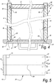
- FIG 5 a method according to the invention is illustrated.
- the drawers 1 comprise at least a front wall 2, rear wall 3 and two sidewalls 4-5 as well as a bottom, and wherein at least two walls, in this case the two sidewalls 4-5 as well as the rear wall 3, comprise profiles which fit into each other in a locking manner and which for this purpose make use of a tongue 10 and groove 11 with locking parts 12-13, wherein these profiles can be joined into each other laterally.
- the groove 11 respectively is provided on the inner side of a sidewall.
- the particularity of the method consists in that at least two walls, in this case the sidewalls 4-5, are made of respectively one board 23.
- the grooves 11 are realized by means of a continuous treatment, whether or not consisting of a plurality of partial treatments, such as milling operations; and only thereafter said board is divided into two or more sidewalls. Such dividing is performed according to the represented line 24, for example, by means of a saw operation, transverse to the profiles, or the groove 10.
- Such drawer can be realized by means of a continuous treatment, more particularly by means of the second possibility thereof mentioned in the introduction.
- the two sidewalls 4-5 preferably are those which are intended to form part of one and the same drawer 1.
- openings 17, such as bore holes, can be provided in the board 23 before the latter is sawn, or beforehand, in order to realize connections with the front wall.
- openings 17, such as bore holes can be provided in the board 23 before the latter is sawn, or beforehand, in order to realize connections with the front wall.
- other post-treatments are not excluded, either.
- Figures 6 to 8 illustrate how front panels or front walls can be manufactured, which are suitable in particular for fitting together in a locking manner with profiles formed on distal ends of sidewalls 4-5 of such drawer 1.
- a front of a drawer 1 is represented, with on the rear side two locking groove profiles 25, to which sidewalls 4-5 can be coupled, wherein the groove profiles 25 are not made continuous on at least one of their ends 26.
- the groove profile 25 is realized by means of one or more cuts by means of one or more rotating cutting tools which engage in the surface from the outside, wherein the cutting tool and the respective panel-shaped element perform a through-feed displacement in the longitudinal direction of the cut, and, for forming said end, locally is moved in and/or out of the surface of the panel-shaped element.
- the cuts are preferably realized by means of saws or saw cutters.
- Figure 7 represents an embodiment wherein the groove profile 25 is realized by means of two cuts 28-29.
- Figure 8 represents a second embodiment, wherein the groove profile is realized by only one cut 30.
- FIG 9 an example of a deviating variant of a drawer 1 is represented, which further illustrates some aspects of the invention, however, which does not belong thereto.
- This drawer 1 comprises at least a front wall 2, more particularly a front panel, two sidewalls 4-5, as well as a bottom 6, with the particular characteristic that the drawer comprises a fitting component 31, which forms part of or directly cooperates with a guide mechanism or fitting mechanism 32 for sliding out the drawer, wherein said fitting component 31 is attached to a sidewall 4-5, on the one hand, and, on the other hand, also provides for a connection with the front wall 2, more particularly the front panel.
- the fitting component hereby obtains an additional function, which results in a stable and advantageous assembly.
- the guiding mechanism 32 is represented only schematically in the form of fitting components, namely, first fitting components 31, which are attached to the drawer, and second fitting components 33, which are fixedly attached to a piece of furniture.
- the portion present therebetween can be of any kind and, for schematization, is omitted in the figure.
- the portion present therebetween can consist of a telescopic system, a roller support, etc.
- the fitting components 31 can be attached to the drawer, in particular to the sidewalls 4-5, in any manner, either by screws or in any other manner.
- these fitting components are situated laterally against the sidewalls 4-5, however, it is clear that, according to a not-represented variant, they can also be mounted, for example, underneath the sides 4-5.
- the attachment between the front wall 2 and the fitting components 31 can also be performed in any manner.
- the first fitting component 31 to this aim is provided with forward-directed protruding portions 35, onto which the front wall, more particularly the front panel, can be fixed in that the portions 35 work in conjunction with openings 16, for example, by means of clamping, glue, etc.
- the sidewalls 4-5 are connected to the rear wall 3 by means of film hinges 36.
- film hinges 36 instead of film hinges use shall be made of coupling means which are formed by profiles which engage in each other, for example, as in figure 2 .
- the drawer preferably is obtained by means of the method of the invention.
- FIG 10 a number of possibilities of drawer constructions are represented in a schematic manner.
- this relates to a drawer construction with a drawer 1 comprising at least a front wall 2, rear wall 3 and two sidewalls 4-5, as well as a bottom 6, with the particularity that the drawer construction as such combines at least the following characteristics:
- the rear wall 3 is located between the sidewalls, and the rear wall 3 is connected to the sidewalls by means of coupling means which allow attaching the sidewalls laterally onto the distal ends of the rear wall, in this case by means of dowels 39.
- the fitting components 31 are attached to the sidewalls 4-5 and movably supported in respect to the fitting components 33 which are intended for being fixedly attached to a piece of furniture.
- connection means 37 should not work correctly.
- fitting components 31 do not necessarily have to be located against the sidewalls 4-5, but can also be mounted underneath the sidewalls.
- a guide mechanism 38A is applied with fitting components 31-33 located underneath the drawer, and wherein, for example, the fitting components 33 are fixedly connected to the front wall 2 and the rear wall 3.
- an internal reinforcement is realized in the drawer, which, in combination with the particular assembly, results in a drawer which can be assembled in a smooth manner and still is clearly stable.
- Figure 10 also illustrates that the sidewalls can be coupled to the front wall by means of a turning movement A from the inside towards the outside.
- Figure 11 represents the use of a dowel 40, which is inserted through the respective sidewall 5.
- the whole shall be made such that the dowel 40 clamps in the rear wall.
- the sidewall it can be made clamping or not.
- a collar or head 41 will be provided in the case of a not-clamping cooperation between the dowel and the sidewall.
- said figure 8 represents a particular example of a front panel.
- the groove or groove profile 25A on the left as well as on the right hand side, is directed outward with its deepest point. This latter offers the advantage that in mounted condition at least the bottom prevents that the sidewalls will come loose from the front wall.
- FIG 12 schematically an example is represented of a device for manufacturing front panels 2.
- the device comprises a continuous system with conveyor belts 42-43, which define an input 44 and output 45.
- the front walls 2 are provided with groove profiles 25 in a first treatment station 46, by means of milling cutters, which preferably engage on the front wall from below.
- bore holes 48 are provided from above, for example, for providing handles.
- a saw 50 by means of a saw 50 a groove 21 is provided in the downward-directed side for attaching the bottom.
- the front wall moves along the rotating saw. The saw possibly may move up and down when the groove does not have to be realized completely continuous.
- the work pieces preferably are lying still.
- Figures 13 and 14 represent how a groove profile 25 can be realized by a milling cutter 51 with an entering movement B1 and a to- and fro-movement B2.
- Figure 13 herein is a schematized view according to arrow F13 in figure 12 .
- Figure 15 shows a variant, wherein an un-doubling is applied by making use of two milling cutters 51, in such a manner that two smaller movements B2 can be applied, which are performed simultaneously, which is time-saving.
- Figure 16 shows a groove profile 25 obtained by means of a variant, wherein an entering movement B1 is made by means of a milling cutter 51, at a distance from the line of movement B2 or the axis 52 of the actual groove profile 25.
- the milling cutter 51 preferably after a widened part 53 of the milling cutter 51 is already situated below the surface of the wall 2 to be milled, and still better after this milling cutter 51 has reached its final depth, performs a lateral movement B3, preferably in the plane of the wall 2. Thereafter, the movement B1 is performed, possibly to and fro, as already described above.
- the distance D is bridged-over again, in opposite direction of the original line of movement B3.
- the distance D in general preferably is smaller than the maximum radius R of the milling cutter 51.
- a distance D has been chosen which corresponds or approximately corresponds to the undercut to be performed.
- the lowermost contours of the obtained groove profile 25 are represented in dashed line 54.
- the advantage of eccentric intrusion or performing the entering movement B1 with the center of the milling cutter at a distance D from the axis 52 of the groove profile 25 has the advantage that a higher quality cut can be obtained.
- the quality of the cut portion 55 increases next to the point 56, where the entering movement B1 or the exiting movement of the milling cutter 51 is performed.
- the improved cut portion 55 preferably is situated on the edge of the groove profile 25 with which the locking part 12 of the tongue 10 cooperates, and/or on the inner side of the composed element or the drawer 1. Improving the quality of the cut is of particular interest for cutting in laminated panels, such as panels which are provided with a decorative layer, for example, of laminate, lacquer, melamine, PVC film, veneer and the like. Improving the quality of the cut is also of interest for milling in panels which substantially consist of particle board, such as wood particle board.
- Another advantage of the eccentric intrusion is that a connection can be obtained over a larger part of the groove profile.
- the cut portion 55 now can also provide an undercut with which the locking part 12 of the tongue 10 can cooperate.
- Figure 17 represents an example, wherein the milling cutter 51 has entered on one side of the groove profile 25 and has exited on the other side, and wherein an eccentric entering/exiting is applied on both sides.
- Figure 18 represents another embodiment of an eccentric entering/exiting of the milling cutter 51, wherein the points 56 of entering and exiting can be found on opposite sides of the axis 52.
- Figure 19 represents another tongue and groove connection which can be applied within the scope of the invention, however, in general can be applied as a corner connection in any composed element.
- the connection in this case the tongue 10, is provided with a flexible material or with a flexible element 57.
- Such element 57 is provided for the annulation of any possible play in the tongue-groove connection.
- the flexible element 57 presses tongue portions, in this case the tongue portions made in one piece with the panel or sidewall 4, against reference surfaces 58-59 of the groove profile 25, by which an acceptable mutual positioning between the connected walls 2-4 can be created.
- Such connection can show less or no play in comparison with a traditional tongue and groove connection.
- a first reference surface 58 of said reference surfaces 58-59 is formed internally in the groove profile 25.
- a second reference surface 59 of said reference surfaces 58-59 is formed on the surface of the wall 2 having the groove profile 52.
- Such arrangement of the reference surfaces is illustrated by means of figure 19 . It is clear that the reference surfaces 58-59 generally preferably extend transverse in mutual respect.
- the flexible element is here provided with a lip 61 which is rotatable around a hinge 60, which lip works in conjunction with the groove profile 25 for achieving said pressing-on.
- a snap effect is applied, such as here, wherein during coupling of the walls 2-4 a to and fro movement of the flexible element 57 or a part thereof is created. It is also possible to apply elastic compression, followed by relaxation of a flexible material.
- a whether or not rigid element can be applied, which, for example, as a wedge, is driven in an opening between the tongue and the groove, whether or not automatically, for achieving said pressing-on against the reference surfaces 58-59.
- Figure 19 represents in dashed line 62 that preferably a space 63 is applied between the surfaces of tongue and groove which do not form part of the reference surfaces 58-59.
- the flexible element 57 or flexible material is located in the groove 11.
- Figure 20 schematically represents an example of a device 64 which applies the method of the invention.
- this relates specifically to an illustration of a continuous treatment according to the first possibility therefor mentioned in the introduction.
- Figure 21 represents that for manufacturing drawers 1 according to the invention it is started from a larger panel or board 23, from which at least two walls 3-4 are obtained.
- three walls 3-4-5 namely two sidewalls 3-5 and a rear wall 4, are obtained from the respective panel or board 23.
- the respective final walls 3-4-5 are located in each other's prolongation in the larger panel or the board 23, namely each time with a distal end of one wall directed to the distal end of another wall.
- dashed line 24 the separation between the respective walls 3-4-5 is represented, as it will be obtained after dividing. The separation extends parallel to said distal ends.
- the larger panel or the board 23 has a core material 65, such as a MDF or HDF panel or a panel of wood particle board, with on both flat sides a decorative layer 66-67, such as, for example, a film or a laminate.
- a core material 65 such as a MDF or HDF panel or a panel of wood particle board
- a decorative layer 66-67 such as, for example, a film or a laminate.
- the invention can also be applied for other types of panels, such as for solid wooden panels.
- profiles are formed by means of milling tools 68-69, which profiles allow joining the finally obtained walls together in a locking manner.
- a tongue 10 and groove 11 with locking parts 12-13 use is made of a tongue 10 and groove 11 with locking parts 12-13, wherein these profiles can be joined together laterally and wherein the respective groove 11 is provided on the inner side of a first wall 3, namely in this case on the inner side of the final rear wall 3, whereas the respective tongue 10 is provided on the narrow side ends 19 of a second wall 4, namely in this case on one of the narrow side end 19 of both final sidewalls 4-5.
- the milling tools 68 engage on both short sides of the larger panel or the board 23; for forming the groove 11 or the groove profile 25, the milling tools 69, for example, as shown here, can engage on one of the flat sides of the larger panel or the board 23.
- a continuous milling machine 70 wherein the larger panel or the board 23 is moved with its short edges over at least two and in this case three milling tools 68. It is known as such, for example, from WO 97/47834 , to form locking profiles on the edge of a panel by means of at least two rotating milling tools. To this aim, preferably two rotating milling tools are applied, which are arranged at a different angle in respect to the panel.
- the device 64 of figure 20 comprises at least two additional rotating milling tools 69 per groove 11 to be milled. In the example, these are arranged in the continuous milling machine 70.
- FIGS 20 to 22 clearly show that said rear wall 3 and both sidewalls 4-5 are made of one and the same board 23 and that herein the respective groove 11 and the respective tongue 10 are formed by means of a treatment, in this case consisting of a plurality of partial treatments, namely a plurality of milling treatments, performed on said larger panel or board 23. Only thereafter the respective board 23 or the larger panel is divided into the respective walls 3-4-5 by means of a dividing device 71, such as a sawing device with one or more rotating saw blades 72.
- a dividing device 71 such as a sawing device with one or more rotating saw blades 72.
- Figure 23 represents the obtained walls 3-4-5.
- Figure 24 represents that, for example, the sidewalls 3-5, can also be post-treated for realizing connection means 9 other than locking profiles, or a portion of such connection means 9 17. In the example, to this aim also bore holes 17 are performed for providing dowels or other connection elements 15 therein.
- Figure 25 represents that, for example, the rear wall 3 can be provided with an edge finish, for example, such as here in the form of a masking tape 73 or ABS strip.
- Figure 26 represents the assembly or the drawer 1 which can be obtained on the basis of the respective sidewalls 4-5 and rear wall 3.
- a front panel or front wall 2 is attached to the narrow side ends 19 of the sidewalls 4-5, by means of said dowels, and a drawer bottom 6 is inserted in grooves 21 provided to this aim in said walls 2-3-4-5.
- Such grooves 21 can be provided in the walls 2-3-4-5 in a similar manner as illustrated in figure 20 .
- Such treatment station 49 is not represented here, however, can be arranged downstream in the device of figure 20 in the same manner as illustrated in figure 12 .
- any locking profiles can be applied, which preferably are laterally insertable. So, for example, possibly the gap 14 can be omitted in the tongues 10.
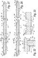
- Figures 27 and 28 represent that according to a preferred embodiment of the method of the invention the profile of a tongue 10A, instead of on the short sides of the larger panel or the board 23, can also be formed centrally in said board 23. Preferably, this is realized, such as here, at the location of a final, obtained after dividing the board 23, narrow-side or distal end 19 of a wall 4-5.
- the tongues 10A are intended for being provided in a groove 11A.
- the grooves 10A have an almost complementary shape, however, possible free intermediate spaces not taken into account.
- the particularity of the profile of the tongues 10A represented in the example also is that the side 74 of the tongue 10A opposite to the side of the locking part 12A, which side 74 in the figure is directed downward, is formed by the surface 75 of the larger panel or the board 23, or that this side 74, in other words, remains untreated. In this manner, it is obtained that the tongue 10A is free from parts, which, seen in the direction of the surface 75, extend beyond the edge 76 of this surface 75. In the case that this surface 75, such as here, is provided with a decorative layer 67, this layer preferably extends uninterruptedly up to the edge 76.
- tongues 10 which in the example are formed on the short sides of the larger panel or the board 23, possibly may show a profile similar or identical to that of the tongues 10A.
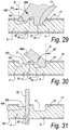
- Figures 29 and 30 represent that such tongue 10A substantially can be obtained by means of cutting treatments which engage on only one flat side 77 of said board 23. In this case, at least the locking parts 12A of the tongue 10A are obtained by means of such cutting treatments.
- Figure 29 as well as figure 30 also illustrate the particular embodiment mentioned in the introduction, wherein at least a partial treatment, in this case the partial treatment of figure 29 , wherein a cutting tool 69A is simultaneously active on two walls, in this case on the sidewall 4 as well as on the rear wall 3.
- the cutting tool 69A engages on the flat side 77 of the board 23 and hereby simultaneously forms parts of a groove 11A and a tongue 10A.
- this relates to portions of a tongue 10A, which fits into the respective groove 11A, however, this is not necessarily the case.
- at least the locking parts 12A-13A either of the tongue 10A or of the groove 11A or of both are formed.
- the locking part 12A of the tongue 10A is formed and simultaneously a part of the profile 25 of the groove 11A.
- a rotating cutting tool 69A is applied.
- the respective cutting tool is arranged inclined and hereby forms an angle B1 of approximately 50° with the normal N of the flat side 77.
- Figure 30 represents how the remaining part of the profile 25 of the groove 10A can be formed with a second cutting tool 69B.
- a rotting cutting tool 69B is applied.
- the rotating cutting tool 69B is arranged inclined and hereby forms an angle B2 of approximately 50° with the normal N of the flat side 77.
- Figures 29 and 30 as such illustrate an embodiment of the invention, wherein exactly two cutting tools 69A-69B are applied for forming the essential part of the groove 11A as well as of the tongue 10A.
- both cutting tools are arranged inclined.
- they both form an angle B1-B2 with the normal N on the surface 77, situated between 5° and 60°, or still better between 40° and 60°.
- these angles are equal or approximately equal for both tools, for example, with a difference of less than 10°, or even less than 5° or less than 2°.
- Figure 31 represents that the dividing of the board 23 also realizes the final part of the profile of the tongue 10A.
- at least the locking parts 12A and 13A of the tongue 10A as well as of the groove 11A are formed, as well as preferably the entire or approximately the entire groove profile 25.
- Figure 32 represents how the rear wall 3 can be connected to a sidewall 4 by means of the mutually cooperating locking profiles of the tongue 10A, on the one hand, and the groove 11A, on the other hand.
- Figure 33 represents another variant of a tongue 10A, wherein also on the surface 75 of the board 23 a treatment is performed by means of a cutting tool 78, such that the tongue 10A, in this case, indeed has portions extending beyond the edge 76 of the surface 75.
- a treatment is performed by means of a cutting tool 78, such that the tongue 10A, in this case, indeed has portions extending beyond the edge 76 of the surface 75.
- the groove profile 25 of the groove 11A is correspondingly adapted as well.
- such treatment is performed prior to dividing the board 23 into the walls 3-4-5 concerned.
Landscapes
- Engineering & Computer Science (AREA)
- Life Sciences & Earth Sciences (AREA)
- Mechanical Engineering (AREA)
- Forests & Forestry (AREA)
- Wood Science & Technology (AREA)
- Furniture Connections (AREA)
- Drawers Of Furniture (AREA)
Claims (14)
- Procédé pour la fabrication de tiroirs ; dans lequel les tiroirs (1) comprennent des parois (2-3-4-5) ainsi qu'un fond (6) ; dans lequel lesdites parois (2-3-4-5) comprennent au moins une paroi avant (2), une paroi arrière (3) et deux parois latérales (4-5) ; et dans lequel au moins une première et une deuxième paroi parmi lesdites parois (3-4) comprennent des profilés qui viennent s'insérer l'un dans l'autre dans une opération de verrouillage et qui, à cet effet, font usage d'une languette (10) et d'une rainure (11) comprenant des éléments de verrouillage (12-13) ; dans lequel lesdits profilés peuvent être joints l'un dans l'autre en direction latérale ; et dans lequel la rainure respective (11) est prévue sur le côté interne de la première paroi (3), tandis que la languette respective (10) est prévue sur l'extrémité distale (19) de la deuxième paroi (4) ; caractérisé en ce que deux parois ou plus sont réalisées à partir d'une seule planche (23) ; en ce que, en l'occurrence, les profils des parois respectives sont réalisés au moyen d'un traitement, constitué ou non d'un certain nombre de traitements partiels, mis en oeuvre sur ladite planche (23) ; et en ce que ladite planche (23) est subdivisée en deux parois (2-3-4-5) ou plus, uniquement après avoir formé au moins des parties desdits profilés.
- Procédé selon la revendication 1, caractérisé en ce que ledit traitement est un traitement en continu.
- Procédé selon l'une quelconque des revendications précédentes, caractérisé en ce qu'au moins ladite première paroi (3) et ladite deuxième paroi (4) sont réalisées à partir de ladite planche unique.
- Procédé selon l'une quelconque des revendications précédentes, caractérisé en ce que lesdits profilés comprennent au moins une languette (10), qui est de préférence réalisée sur une extrémité distale de ladite planche (23).
- Procédé selon l'une quelconque des revendications précédentes, caractérisé en ce que lesdits profilés comprennent au moins une rainure (11), qui est de préférence réalisée dans un côté plat de ladite planche (23).
- Procédé selon l'une quelconque des revendications précédentes, caractérisé en ce que l'on obtient trois parois à partir de ladite planche (23), plus précisément deux parois latérales (4-5) et une paroi avant (2) ou une paroi arrière (3).
- Procédé selon l'une quelconque des revendications précédentes, caractérisé en ce que tous les profilés de verrouillage des parois respectives (3-4) sont réalisés au moins en partie, voire complètement, avant la subdivision de ladite planche (23) pour obtenir les parois respectives (3-4).
- Procédé selon l'une quelconque des revendications précédentes, caractérisé en ce que, après la subdivision de la planche respective (2), encore un ou plusieurs traitements sont mis en oeuvre sur une ou plusieurs des parois obtenues (3-4).
- Procédé selon la revendication 8, caractérisé en ce que, après la subdivision, un ou plusieurs traitements sont mis en oeuvre pour la réalisation de moyens de liaison (9) autres que des profilés de verrouillage.
- Procédé selon la revendication 8 ou 9, caractérisé en ce que, après la subdivision, une ou plusieurs opérations de fraisage sont mises en oeuvre afin d'obtenir des chevilles ou d'autres éléments de fixation (15).
- Procédé selon l'une quelconque des revendications 8 à 10, caractérisée en ce que, après la subdivision, une ou plusieurs opérations de masquage sont mises en oeuvre, par exemple au moyen d'une bande stratifiée ou d'une bande ABS.
- Procédé selon l'une quelconque des revendications précédentes, caractérisé en ce que la planche (23), dans un dispositif prévu à cet effet, est transportée au moyen d'un système continu, à partir d'une entrée (44), en passant par au moins un poste de traitement, jusqu'à une sortie (45) ; dans lequel le profil (25) de la rainure est établi dans le poste de traitement au moyen d'au moins une fraiseuse (69).
- Procédé selon l'une quelconque des revendications précédentes, caractérisé en ce que ledit traitement englobe au moins un traitement partiel ; dans lequel un outil de coupe est actif de manière simultanée sur les deux parois.
- Dispositif pour la mise en oeuvre du procédé selon l'une quelconque des revendications précédentes, caractérisé en ce qu'il est constitué par un système continu et par divers postes de traitement (70-71) installés le long dudit système, pour la réalisation d'un ou de plusieurs des traitements qui sont décrits dans les revendications précédentes.
Applications Claiming Priority (2)
| Application Number | Priority Date | Filing Date | Title |
|---|---|---|---|
| US201261597992P | 2012-02-13 | 2012-02-13 | |
| PCT/IB2013/050948 WO2013121320A1 (fr) | 2012-02-13 | 2013-02-05 | Procédé de fabrication d'un tiroir |
Publications (2)
| Publication Number | Publication Date |
|---|---|
| EP2814357A1 EP2814357A1 (fr) | 2014-12-24 |
| EP2814357B1 true EP2814357B1 (fr) | 2018-10-17 |
Family
ID=48048077
Family Applications (1)
| Application Number | Title | Priority Date | Filing Date |
|---|---|---|---|
| EP13714332.7A Active EP2814357B1 (fr) | 2012-02-13 | 2013-02-05 | Procédé de fabrication d'un tiroir |
Country Status (4)
| Country | Link |
|---|---|
| US (1) | US20150320210A1 (fr) |
| EP (1) | EP2814357B1 (fr) |
| TR (1) | TR201820039T4 (fr) |
| WO (1) | WO2013121320A1 (fr) |
Families Citing this family (6)
| Publication number | Priority date | Publication date | Assignee | Title |
|---|---|---|---|---|
| BE1020495A4 (nl) | 2012-02-08 | 2013-11-05 | Unilin Bvba | Samengesteld element en hoekverbinding hierbij toegepast. |
| BE1022484B1 (nl) | 2014-10-17 | 2016-05-03 | Unilin Bvba | Samengesteld element, lade en werkwijze voor het vervaardigen van dergelijke lade |
| CN105996511A (zh) * | 2016-07-18 | 2016-10-12 | 佛山市南海新达高梵实业有限公司 | 一种易于组装的抽屉框架结构及其生产工艺 |
| WO2019246458A1 (fr) * | 2018-06-20 | 2019-12-26 | Adeptus IP, LLC | Kit de meuble prêt à monter (rta), structure et procédé de montage |
| US20220288810A1 (en) * | 2021-03-12 | 2022-09-15 | Ideal Cabinet Operations, Ltd. | Outdoor cabinet |
| US20250000256A1 (en) * | 2022-10-17 | 2025-01-02 | Leyo Holdings Sdn Bhd | Drawer Assembly |
Family Cites Families (18)
| Publication number | Priority date | Publication date | Assignee | Title |
|---|---|---|---|---|
| US115116A (en) * | 1871-05-23 | Improvement in burial-cases | ||
| US1169328A (en) * | 1912-07-06 | 1916-01-25 | Henry M Holtgrewe | Knockdown drawer. |
| US1468786A (en) * | 1922-02-04 | 1923-09-25 | Jacob S Knechtel | Cabinet joint |
| US1954242A (en) * | 1932-07-28 | 1934-04-10 | Thomas E Heppenstall | Dovetail spring joint |
| US2496184A (en) * | 1946-06-11 | 1950-01-31 | Canon Paul L Von | Furniture drawer construction and method |
| US2551775A (en) * | 1946-11-22 | 1951-05-08 | Canon Paul L Von | Corner joint structure for knockdown boxes |
| US3539425A (en) * | 1966-11-09 | 1970-11-10 | Arthur Marburg | Method of assembling the walls of a box-like structure |
| US3933401A (en) * | 1971-03-23 | 1976-01-20 | Armstrong Cork Company | Foamed poly(vinyl chloride) drawer sides |
| US4005738A (en) * | 1975-07-31 | 1977-02-01 | Manufacturing Approaches & Total Concepts Inc. | Automatic dadoing machine |
| US4422488A (en) * | 1981-09-09 | 1983-12-27 | Centre De Recherche Industrielle Du Quebec | Machine for producing drawer-sides |
| US4471822A (en) * | 1983-02-04 | 1984-09-18 | Goldenhill Wood Products, Inc. | Machine for manufacturing drawer sides |
| US5555989A (en) * | 1991-04-11 | 1996-09-17 | Qube Corporation | Plastic enclosures |
| US5597221A (en) * | 1995-11-01 | 1997-01-28 | Sauder Woodworking Co. | Drawer assembly having interlocking members |
| BE1010487A6 (nl) | 1996-06-11 | 1998-10-06 | Unilin Beheer Bv | Vloerbekleding bestaande uit harde vloerpanelen en werkwijze voor het vervaardigen van dergelijke vloerpanelen. |
| US6413007B1 (en) * | 2000-05-01 | 2002-07-02 | Sauder Woodworking Co. | Joint assembly |
| BE1018389A3 (nl) | 2008-12-17 | 2010-10-05 | Unilin Bvba | Samengesteld element, meerlagige plaat en paneelvormig element voor het vormen van zulk samengesteld element. |
| EP2526819A1 (fr) * | 2011-05-25 | 2012-11-28 | Steen Sauer | Assemblage pour tiroir |
| BE1020044A5 (nl) * | 2011-06-29 | 2013-04-02 | Unilin Bvba | Lade, ladeconstructie en werkwijze voor het vervaardigen van een lade. |
-
2013
- 2013-02-05 WO PCT/IB2013/050948 patent/WO2013121320A1/fr not_active Ceased
- 2013-02-05 US US14/378,378 patent/US20150320210A1/en not_active Abandoned
- 2013-02-05 EP EP13714332.7A patent/EP2814357B1/fr active Active
- 2013-02-05 TR TR2018/20039T patent/TR201820039T4/tr unknown
Non-Patent Citations (1)
| Title |
|---|
| None * |
Also Published As
| Publication number | Publication date |
|---|---|
| US20150320210A1 (en) | 2015-11-12 |
| EP2814357A1 (fr) | 2014-12-24 |
| TR201820039T4 (tr) | 2019-01-21 |
| WO2013121320A1 (fr) | 2013-08-22 |
Similar Documents
| Publication | Publication Date | Title |
|---|---|---|
| US10293512B2 (en) | Drawer, drawer construction and method for manufacturing a drawer | |
| EP2814357B1 (fr) | Procédé de fabrication d'un tiroir | |
| CA3011421C (fr) | Procede pour former un panneau pour un produit de mobilier | |
| US10524567B2 (en) | Composed element and corner connection applied herewith | |
| EP2712518B1 (fr) | Élément composite | |
| EP3353429B1 (fr) | Set de panneaux comportant un dispositif de verrouillage mécanique et methode de des-assemblage de ces panneaux | |
| RU2576584C1 (ru) | Облегченная плита, соединительное устройство и способ его изготовления | |
| US7051486B2 (en) | Mechanical locking system for floating floor | |
| CN100447362C (zh) | 包含连接装置的地板块以及用于制造该地板块的方法 | |
| EP2064035B1 (fr) | Procédé de fabrication de panneaux de plancher | |
| CA3096816A1 (fr) | Languette symetrique et croix en t | |
| RU2010114465A (ru) | Способ изготовления панели, прежде всего половой панели | |
| KR20170095950A (ko) | 기계식 잠금 디바이스를 포함하는 패널들 및 패널들을 포함하는 조립된 제품 | |
| DE102004007157B4 (de) | Verfahren zum Herstellen von Platten aus Holz und/oder Holzersatzstoffen und danach hergestellte Platte | |
| US20250059820A1 (en) | Cabinet door assembly and manufacturing thereof | |
| US20120276319A1 (en) | Three or five piece component | |
| BE1020079A3 (nl) | Werkwijze voor het vervaardigen van een lade. | |
| SK3162003A3 (en) | Grooved laths and self-catching tabs for forming floors and method for machining said laths | |
| EP4686834A1 (fr) | Serrure à auto-serrage | |
| CA2998878C (fr) | Panneaux comportant un dispositif de verrouillage mecanique et produit assemble comportant les panneaux |
Legal Events
| Date | Code | Title | Description |
|---|---|---|---|
| PUAI | Public reference made under article 153(3) epc to a published international application that has entered the european phase |
Free format text: ORIGINAL CODE: 0009012 |
|
| 17P | Request for examination filed |
Effective date: 20140710 |
|
| AK | Designated contracting states |
Kind code of ref document: A1 Designated state(s): AL AT BE BG CH CY CZ DE DK EE ES FI FR GB GR HR HU IE IS IT LI LT LU LV MC MK MT NL NO PL PT RO RS SE SI SK SM TR |
|
| AX | Request for extension of the european patent |
Extension state: BA ME |
|
| DAX | Request for extension of the european patent (deleted) | ||
| REG | Reference to a national code |
Ref country code: DE Ref legal event code: R079 Ref document number: 602013045179 Country of ref document: DE Free format text: PREVIOUS MAIN CLASS: A47B0088000000 Ipc: A47B0088900000 |
|
| GRAP | Despatch of communication of intention to grant a patent |
Free format text: ORIGINAL CODE: EPIDOSNIGR1 |
|
| STAA | Information on the status of an ep patent application or granted ep patent |
Free format text: STATUS: GRANT OF PATENT IS INTENDED |
|
| RIC1 | Information provided on ipc code assigned before grant |
Ipc: B27F 4/00 20060101ALI20180409BHEP Ipc: B27F 1/08 20060101ALI20180409BHEP Ipc: A47B 88/90 20170101AFI20180409BHEP |
|
| INTG | Intention to grant announced |
Effective date: 20180511 |
|
| GRAS | Grant fee paid |
Free format text: ORIGINAL CODE: EPIDOSNIGR3 |
|
| GRAA | (expected) grant |
Free format text: ORIGINAL CODE: 0009210 |
|
| STAA | Information on the status of an ep patent application or granted ep patent |
Free format text: STATUS: THE PATENT HAS BEEN GRANTED |
|
| AK | Designated contracting states |
Kind code of ref document: B1 Designated state(s): AL AT BE BG CH CY CZ DE DK EE ES FI FR GB GR HR HU IE IS IT LI LT LU LV MC MK MT NL NO PL PT RO RS SE SI SK SM TR |
|
| REG | Reference to a national code |
Ref country code: GB Ref legal event code: FG4D |
|
| REG | Reference to a national code |
Ref country code: CH Ref legal event code: EP |
|
| REG | Reference to a national code |
Ref country code: IE Ref legal event code: FG4D |
|
| REG | Reference to a national code |
Ref country code: DE Ref legal event code: R096 Ref document number: 602013045179 Country of ref document: DE Ref country code: AT Ref legal event code: REF Ref document number: 1052959 Country of ref document: AT Kind code of ref document: T Effective date: 20181115 |
|
| REG | Reference to a national code |
Ref country code: NL Ref legal event code: MP Effective date: 20181017 |
|
| REG | Reference to a national code |
Ref country code: LT Ref legal event code: MG4D |
|
| REG | Reference to a national code |
Ref country code: AT Ref legal event code: MK05 Ref document number: 1052959 Country of ref document: AT Kind code of ref document: T Effective date: 20181017 |
|
| PG25 | Lapsed in a contracting state [announced via postgrant information from national office to epo] |
Ref country code: NL Free format text: LAPSE BECAUSE OF FAILURE TO SUBMIT A TRANSLATION OF THE DESCRIPTION OR TO PAY THE FEE WITHIN THE PRESCRIBED TIME-LIMIT Effective date: 20181017 |
|
| PG25 | Lapsed in a contracting state [announced via postgrant information from national office to epo] |
Ref country code: AT Free format text: LAPSE BECAUSE OF FAILURE TO SUBMIT A TRANSLATION OF THE DESCRIPTION OR TO PAY THE FEE WITHIN THE PRESCRIBED TIME-LIMIT Effective date: 20181017 Ref country code: LV Free format text: LAPSE BECAUSE OF FAILURE TO SUBMIT A TRANSLATION OF THE DESCRIPTION OR TO PAY THE FEE WITHIN THE PRESCRIBED TIME-LIMIT Effective date: 20181017 Ref country code: ES Free format text: LAPSE BECAUSE OF FAILURE TO SUBMIT A TRANSLATION OF THE DESCRIPTION OR TO PAY THE FEE WITHIN THE PRESCRIBED TIME-LIMIT Effective date: 20181017 Ref country code: LT Free format text: LAPSE BECAUSE OF FAILURE TO SUBMIT A TRANSLATION OF THE DESCRIPTION OR TO PAY THE FEE WITHIN THE PRESCRIBED TIME-LIMIT Effective date: 20181017 Ref country code: BG Free format text: LAPSE BECAUSE OF FAILURE TO SUBMIT A TRANSLATION OF THE DESCRIPTION OR TO PAY THE FEE WITHIN THE PRESCRIBED TIME-LIMIT Effective date: 20190117 Ref country code: PL Free format text: LAPSE BECAUSE OF FAILURE TO SUBMIT A TRANSLATION OF THE DESCRIPTION OR TO PAY THE FEE WITHIN THE PRESCRIBED TIME-LIMIT Effective date: 20181017 Ref country code: HR Free format text: LAPSE BECAUSE OF FAILURE TO SUBMIT A TRANSLATION OF THE DESCRIPTION OR TO PAY THE FEE WITHIN THE PRESCRIBED TIME-LIMIT Effective date: 20181017 Ref country code: FI Free format text: LAPSE BECAUSE OF FAILURE TO SUBMIT A TRANSLATION OF THE DESCRIPTION OR TO PAY THE FEE WITHIN THE PRESCRIBED TIME-LIMIT Effective date: 20181017 Ref country code: NO Free format text: LAPSE BECAUSE OF FAILURE TO SUBMIT A TRANSLATION OF THE DESCRIPTION OR TO PAY THE FEE WITHIN THE PRESCRIBED TIME-LIMIT Effective date: 20190117 Ref country code: IS Free format text: LAPSE BECAUSE OF FAILURE TO SUBMIT A TRANSLATION OF THE DESCRIPTION OR TO PAY THE FEE WITHIN THE PRESCRIBED TIME-LIMIT Effective date: 20190217 |
|
| PG25 | Lapsed in a contracting state [announced via postgrant information from national office to epo] |
Ref country code: RS Free format text: LAPSE BECAUSE OF FAILURE TO SUBMIT A TRANSLATION OF THE DESCRIPTION OR TO PAY THE FEE WITHIN THE PRESCRIBED TIME-LIMIT Effective date: 20181017 Ref country code: GR Free format text: LAPSE BECAUSE OF FAILURE TO SUBMIT A TRANSLATION OF THE DESCRIPTION OR TO PAY THE FEE WITHIN THE PRESCRIBED TIME-LIMIT Effective date: 20190118 Ref country code: AL Free format text: LAPSE BECAUSE OF FAILURE TO SUBMIT A TRANSLATION OF THE DESCRIPTION OR TO PAY THE FEE WITHIN THE PRESCRIBED TIME-LIMIT Effective date: 20181017 Ref country code: PT Free format text: LAPSE BECAUSE OF FAILURE TO SUBMIT A TRANSLATION OF THE DESCRIPTION OR TO PAY THE FEE WITHIN THE PRESCRIBED TIME-LIMIT Effective date: 20190217 Ref country code: SE Free format text: LAPSE BECAUSE OF FAILURE TO SUBMIT A TRANSLATION OF THE DESCRIPTION OR TO PAY THE FEE WITHIN THE PRESCRIBED TIME-LIMIT Effective date: 20181017 |
|
| REG | Reference to a national code |
Ref country code: DE Ref legal event code: R097 Ref document number: 602013045179 Country of ref document: DE |
|
| PG25 | Lapsed in a contracting state [announced via postgrant information from national office to epo] |
Ref country code: DK Free format text: LAPSE BECAUSE OF FAILURE TO SUBMIT A TRANSLATION OF THE DESCRIPTION OR TO PAY THE FEE WITHIN THE PRESCRIBED TIME-LIMIT Effective date: 20181017 Ref country code: CZ Free format text: LAPSE BECAUSE OF FAILURE TO SUBMIT A TRANSLATION OF THE DESCRIPTION OR TO PAY THE FEE WITHIN THE PRESCRIBED TIME-LIMIT Effective date: 20181017 Ref country code: IT Free format text: LAPSE BECAUSE OF FAILURE TO SUBMIT A TRANSLATION OF THE DESCRIPTION OR TO PAY THE FEE WITHIN THE PRESCRIBED TIME-LIMIT Effective date: 20181017 |
|
| PLBE | No opposition filed within time limit |
Free format text: ORIGINAL CODE: 0009261 |
|
| STAA | Information on the status of an ep patent application or granted ep patent |
Free format text: STATUS: NO OPPOSITION FILED WITHIN TIME LIMIT |
|
| PG25 | Lapsed in a contracting state [announced via postgrant information from national office to epo] |
Ref country code: SK Free format text: LAPSE BECAUSE OF FAILURE TO SUBMIT A TRANSLATION OF THE DESCRIPTION OR TO PAY THE FEE WITHIN THE PRESCRIBED TIME-LIMIT Effective date: 20181017 Ref country code: EE Free format text: LAPSE BECAUSE OF FAILURE TO SUBMIT A TRANSLATION OF THE DESCRIPTION OR TO PAY THE FEE WITHIN THE PRESCRIBED TIME-LIMIT Effective date: 20181017 Ref country code: SM Free format text: LAPSE BECAUSE OF FAILURE TO SUBMIT A TRANSLATION OF THE DESCRIPTION OR TO PAY THE FEE WITHIN THE PRESCRIBED TIME-LIMIT Effective date: 20181017 Ref country code: RO Free format text: LAPSE BECAUSE OF FAILURE TO SUBMIT A TRANSLATION OF THE DESCRIPTION OR TO PAY THE FEE WITHIN THE PRESCRIBED TIME-LIMIT Effective date: 20181017 |
|
| 26N | No opposition filed |
Effective date: 20190718 |
|
| REG | Reference to a national code |
Ref country code: CH Ref legal event code: PL |
|
| GBPC | Gb: european patent ceased through non-payment of renewal fee |
Effective date: 20190205 |
|
| PG25 | Lapsed in a contracting state [announced via postgrant information from national office to epo] |
Ref country code: MC Free format text: LAPSE BECAUSE OF FAILURE TO SUBMIT A TRANSLATION OF THE DESCRIPTION OR TO PAY THE FEE WITHIN THE PRESCRIBED TIME-LIMIT Effective date: 20181017 Ref country code: LU Free format text: LAPSE BECAUSE OF NON-PAYMENT OF DUE FEES Effective date: 20190205 Ref country code: SI Free format text: LAPSE BECAUSE OF FAILURE TO SUBMIT A TRANSLATION OF THE DESCRIPTION OR TO PAY THE FEE WITHIN THE PRESCRIBED TIME-LIMIT Effective date: 20181017 |
|
| REG | Reference to a national code |
Ref country code: IE Ref legal event code: MM4A |
|
| PG25 | Lapsed in a contracting state [announced via postgrant information from national office to epo] |
Ref country code: LI Free format text: LAPSE BECAUSE OF NON-PAYMENT OF DUE FEES Effective date: 20190228 Ref country code: CH Free format text: LAPSE BECAUSE OF NON-PAYMENT OF DUE FEES Effective date: 20190228 |
|
| PG25 | Lapsed in a contracting state [announced via postgrant information from national office to epo] |
Ref country code: IE Free format text: LAPSE BECAUSE OF NON-PAYMENT OF DUE FEES Effective date: 20190205 Ref country code: GB Free format text: LAPSE BECAUSE OF NON-PAYMENT OF DUE FEES Effective date: 20190205 |
|
| PG25 | Lapsed in a contracting state [announced via postgrant information from national office to epo] |
Ref country code: MT Free format text: LAPSE BECAUSE OF NON-PAYMENT OF DUE FEES Effective date: 20190205 |
|
| PG25 | Lapsed in a contracting state [announced via postgrant information from national office to epo] |
Ref country code: CY Free format text: LAPSE BECAUSE OF FAILURE TO SUBMIT A TRANSLATION OF THE DESCRIPTION OR TO PAY THE FEE WITHIN THE PRESCRIBED TIME-LIMIT Effective date: 20181017 |
|
| PG25 | Lapsed in a contracting state [announced via postgrant information from national office to epo] |
Ref country code: HU Free format text: LAPSE BECAUSE OF FAILURE TO SUBMIT A TRANSLATION OF THE DESCRIPTION OR TO PAY THE FEE WITHIN THE PRESCRIBED TIME-LIMIT; INVALID AB INITIO Effective date: 20130205 |
|
| PG25 | Lapsed in a contracting state [announced via postgrant information from national office to epo] |
Ref country code: MK Free format text: LAPSE BECAUSE OF FAILURE TO SUBMIT A TRANSLATION OF THE DESCRIPTION OR TO PAY THE FEE WITHIN THE PRESCRIBED TIME-LIMIT Effective date: 20181017 |
|
| REG | Reference to a national code |
Ref country code: DE Ref legal event code: R081 Ref document number: 602013045179 Country of ref document: DE Owner name: FLOORING INDUSTRIES LIMITED, SARL, LU Free format text: FORMER OWNER: UNILIN, BVBA, WIELSBEKE, BE Ref country code: DE Ref legal event code: R081 Ref document number: 602013045179 Country of ref document: DE Owner name: UNILIN BV, BE Free format text: FORMER OWNER: UNILIN, BVBA, WIELSBEKE, BE |
|
| P01 | Opt-out of the competence of the unified patent court (upc) registered |
Effective date: 20230428 |
|
| REG | Reference to a national code |
Ref country code: BE Ref legal event code: PD Owner name: FLOORING INDUSTRIES LIMITED, SARL; LU Free format text: DETAILS ASSIGNMENT: CHANGE OF OWNER(S), CHANGE OF LEGAL ENTITY; FORMER OWNER NAME: UNILIN Effective date: 20230602 |
|
| P02 | Opt-out of the competence of the unified patent court (upc) changed |
Effective date: 20230907 |
|
| REG | Reference to a national code |
Ref country code: DE Ref legal event code: R081 Ref document number: 602013045179 Country of ref document: DE Owner name: UNILIN BV, BE Free format text: FORMER OWNER: FLOORING INDUSTRIES LIMITED, SARL, BERTRANGE, LU |
|
| REG | Reference to a national code |
Ref country code: BE Ref legal event code: PD Owner name: UNILIN BV; BE Free format text: DETAILS ASSIGNMENT: CHANGE OF OWNER(S), ASSIGNMENT; FORMER OWNER NAME: FLOORING INDUSTRIES LIMITED, SARL Effective date: 20240320 |
|
| PGFP | Annual fee paid to national office [announced via postgrant information from national office to epo] |
Ref country code: BE Payment date: 20250227 Year of fee payment: 13 |
|
| PGFP | Annual fee paid to national office [announced via postgrant information from national office to epo] |
Ref country code: FR Payment date: 20250225 Year of fee payment: 13 |
|
| PGFP | Annual fee paid to national office [announced via postgrant information from national office to epo] |
Ref country code: DE Payment date: 20260227 Year of fee payment: 14 |
|
| PGFP | Annual fee paid to national office [announced via postgrant information from national office to epo] |
Ref country code: TR Payment date: 20260127 Year of fee payment: 14 |