EP2814399B1 - Ventilanordnung für eine biopsievorrichtung - Google Patents
Ventilanordnung für eine biopsievorrichtung Download PDFInfo
- Publication number
- EP2814399B1 EP2814399B1 EP13749571.9A EP13749571A EP2814399B1 EP 2814399 B1 EP2814399 B1 EP 2814399B1 EP 13749571 A EP13749571 A EP 13749571A EP 2814399 B1 EP2814399 B1 EP 2814399B1
- Authority
- EP
- European Patent Office
- Prior art keywords
- valve
- cutter
- needle
- biopsy
- assembly
- Prior art date
- Legal status (The legal status is an assumption and is not a legal conclusion. Google has not performed a legal analysis and makes no representation as to the accuracy of the status listed.)
- Active
Links
Images








Classifications
-
- A—HUMAN NECESSITIES
- A61—MEDICAL OR VETERINARY SCIENCE; HYGIENE
- A61B—DIAGNOSIS; SURGERY; IDENTIFICATION
- A61B10/00—Instruments for taking body samples for diagnostic purposes; Other methods or instruments for diagnosis, e.g. for vaccination diagnosis, sex determination or ovulation-period determination; Throat striking implements
- A61B10/02—Instruments for taking cell samples or for biopsy
- A61B10/0233—Pointed or sharp biopsy instruments
- A61B10/0283—Pointed or sharp biopsy instruments with vacuum aspiration, e.g. caused by retractable plunger or by connected syringe
-
- A—HUMAN NECESSITIES
- A61—MEDICAL OR VETERINARY SCIENCE; HYGIENE
- A61B—DIAGNOSIS; SURGERY; IDENTIFICATION
- A61B10/00—Instruments for taking body samples for diagnostic purposes; Other methods or instruments for diagnosis, e.g. for vaccination diagnosis, sex determination or ovulation-period determination; Throat striking implements
- A61B10/02—Instruments for taking cell samples or for biopsy
- A61B10/0233—Pointed or sharp biopsy instruments
- A61B10/0266—Pointed or sharp biopsy instruments means for severing sample
-
- A—HUMAN NECESSITIES
- A61—MEDICAL OR VETERINARY SCIENCE; HYGIENE
- A61B—DIAGNOSIS; SURGERY; IDENTIFICATION
- A61B10/00—Instruments for taking body samples for diagnostic purposes; Other methods or instruments for diagnosis, e.g. for vaccination diagnosis, sex determination or ovulation-period determination; Throat striking implements
- A61B10/02—Instruments for taking cell samples or for biopsy
- A61B10/0233—Pointed or sharp biopsy instruments
- A61B10/0266—Pointed or sharp biopsy instruments means for severing sample
- A61B10/0275—Pointed or sharp biopsy instruments means for severing sample with sample notch, e.g. on the side of inner stylet
-
- A—HUMAN NECESSITIES
- A61—MEDICAL OR VETERINARY SCIENCE; HYGIENE
- A61B—DIAGNOSIS; SURGERY; IDENTIFICATION
- A61B17/00—Surgical instruments, devices or methods
- A61B17/34—Trocars; Puncturing needles
- A61B17/3498—Valves therefor, e.g. flapper valves, slide valves
-
- A—HUMAN NECESSITIES
- A61—MEDICAL OR VETERINARY SCIENCE; HYGIENE
- A61M—DEVICES FOR INTRODUCING MEDIA INTO, OR ONTO, THE BODY; DEVICES FOR TRANSDUCING BODY MEDIA OR FOR TAKING MEDIA FROM THE BODY; DEVICES FOR PRODUCING OR ENDING SLEEP OR STUPOR
- A61M39/00—Tubes, tube connectors, tube couplings, valves, access sites or the like, specially adapted for medical use
- A61M39/22—Valves or arrangement of valves
-
- A—HUMAN NECESSITIES
- A61—MEDICAL OR VETERINARY SCIENCE; HYGIENE
- A61B—DIAGNOSIS; SURGERY; IDENTIFICATION
- A61B10/00—Instruments for taking body samples for diagnostic purposes; Other methods or instruments for diagnosis, e.g. for vaccination diagnosis, sex determination or ovulation-period determination; Throat striking implements
- A61B10/02—Instruments for taking cell samples or for biopsy
- A61B2010/0208—Biopsy devices with actuators, e.g. with triggered spring mechanisms
Definitions
- Biopsy samples have been obtained in a variety of ways in various medical procedures using a variety of devices.
- Biopsy devices may be used under stereotactic guidance, ultrasound guidance, MRI guidance, PEM guidance, BSGI guidance, or otherwise.
- some biopsy devices may be fully operable by a user using a single hand, and with a single insertion, to capture one or more biopsy samples from a patient.
- some biopsy devices may be tethered to a vacuum module and/or control module, such as for communication of fluids (e.g., pressurized air, saline, atmospheric air, vacuum, etc.), for communication of power, and/or for communication of commands and the like.
- Other biopsy devices may be fully or at least partially operable without being tethered or otherwise connected with another device.
- Document US 6,162,187 discloses a biopsy device comprising a body, a needle and a cutter. Further, a vacuum source and a valve assembly in fluid communication with the needle of the biopsy device are disclosed.
- the disclosed valve assembly includes a first and a second valve for providing a vacuum and atmospheric venting to the needle of the biopsy device.
- FIG. 1 depicts an exemplary biopsy device (10), an exemplary control unit (20), an exemplary valve assembly unit (100), and a saline bag (50).
- Saline bag (50) is fluidly coupled to valve assembly unit (100) to provide a source of saline to biopsy device (10).
- Biopsy device (10) of this example comprises a probe (12) and a holster (14).
- a needle (16) extends distally from probe (12), and is inserted into a patient's tissue to obtain tissue samples. The tissue samples are deposited in a tissue sample holder (18) at the proximal end of probe (12).
- probe (12) may be removably secured to holster (14) by a variety of structures, components, features, etc. (e.g., bayonet mounts, latches, prongs, clamps, clips, snap fittings, etc.).
- probe (12) and holster (14) may be of unitary or integral construction, such that the two components cannot be separated.
- probe (12) and holster (14) are provided as separable components
- probe (12) may be provided as a disposable component
- holster (14) may be provided as a reusable component. Still other suitable structural and functional relationships between probe (12) and holster (14) will be apparent to those of ordinary skill in the art in view of the teachings herein.
- Needle (16) of the present example comprises a cannula (31) with a tissue piercing tip (32), a lateral aperture (34), a first lumen (36), and a second lumen (38), as shown in FIG. 2 .
- Tissue piercing tip (32) is configured to pierce and penetrate tissue, without requiring a high amount of force, and without requiring an opening to be preformed in the tissue prior to insertion of tip (32).
- a cutter (50) is disposed in first lumen (36), and is operable to rotate and translate within first lumen (36).
- Lateral aperture (34) is located proximal to tip (32), is in fluid communication with first lumen (36), and is configured to receive tissue when needle (16) is inserted in a biopsy site and when cutter (50) is retracted.
- a plurality of openings (37) provide fluid communication between first and second lumens (36, 38).
- Cutter (50) of the present example is substantially hollow, such that cutter (50) defines a cutter lumen (52).
- Cutter (50) also has a substantially sharp distal edge (51), such that cutter (50) is operable to sever a biopsy sample from tissue protruding through lateral aperture (34) of needle (16).
- Biopsy device (10) may be further constructed in accordance with at least some of the teachings of U.S. Pat. No. 5,526,822 , entitled “Method and Apparatus for Automated Biopsy and Collection of Soft Tissue,” issued June 18, 1996; U.S. Pat. No. 6,086,544 , entitled “Control Apparatus for an Automated Surgical Biopsy Device,” issued July 11, 2000; U.S. Pat. No. 6,626,849 , entitled “MRI Compatible Surgical Biopsy Device,” issued September 11, 2003; U.S. Pat. No. 7,442,171 , entitled “Remote Thumbwheel for a Surgical Biopsy Device,” issued October 8, 2008; U.S. Pat. No.
- Non-Provisional Patent App. No. 13/086,567 entitled “Biopsy Device with Motorized Needle Firing,” filed April 14, 2011, published as U.S. Pat. Pub. No. 2012/0265095 on October 18, 2012
- U.S. Non-Provisional Patent App. No. 13/150,950 entitled “Needle Assembly and Blade Assembly for Biopsy Device,” filed June 1, 2011, published as U.S. Pat. Pub. No. 2012/0310110 on December 6, 2012
- U.S. Non-Provisional Patent App. No. 13/205,189 entitled “Access Chamber and Markers for Biopsy Device,” filed August 8, 2011
- biopsy device 10
- biopsy device 10
- control unit (20) of the present example comprises a valve assembly receptacle (22), a pair of valve actuators (24), and a vacuum canister (26).
- Valve assembly receptacle (22) is configured to receive a proximal end (206) of a valve assembly (200) of valve assembly unit (100), as will be described in greater detail below.
- Receptacle (22) of the present example includes a substantially rectangular central portion (not shown) having a downward ledge (not shown) that longitudinally secures valve assembly (200) to control unit (20) when valve assembly (200) is inserted therein.
- a pair of cylindrical receptacles (not shown) for receptacle (22) are axially aligned with a corresponding valve actuator (24).
- valve assembly (200) is inserted into receptacle (22)
- a shaft of each actuator (24) is keyed to insert into a key slot (228, 328) of a corresponding valve spool (214, 314) of valves (210, 300) such that rotation of one or both shafts of actuators (24) rotate a corresponding valve spool (214, 314).
- actuators (24) comprise stepper motors, though it should be understood that other motors or control devices to rotate valve spools (214, 314) may be used, as will be apparent to one of ordinary skill in the art in view of the teachings herein.
- Actuators (24) drive first valve (210) and second valve (300) according to a sequence or sequences to control the flow of fluids through valve assembly (200) during a biopsy procedure.
- Merely exemplary sequences for controlling biopsy device (10) may be configured such as those disclosed in U.S. Pat. No. 7,938,786 , entitled “Vacuum Timing Algorithm for Biopsy Device,” issued May 10, 2011; in U.S. Non-Provisional Patent App. No. 12/953,715 , entitled “Handheld Biopsy Device with Needle Firing,” filed November 24, 2010, published as U.S. Pat. Pub. No.
- sequences of the present example are pre-programmed into the control unit (20) so that either a negative (vacuum) pressure, an ambient (atmospheric) pressure (e.g., venting), a dead head, and/or a saline supply is supplied to the lines (102, 104, 106) to biopsy device (10), as will be described in greater detail below.
- the sequences may be manually controlled via buttons, knobs, touch screen icons, other components associated with control unit (20).
- control unit (20) may be further constructed in accordance with at least some of the teachings of U.S. Pat. No.
- Control unit (20) also includes a vacuum canister (26) through which a vacuum is provided to biopsy device (10).
- Vacuum canister (26) is configured such that fluids from biopsy device (10) are deposited within vacuum canister (26) while a vacuum is provided to biopsy device.
- Vacuum canister may be further constructed in accordance with at least some of the teachings of U.S. Pat. No. 7,575,556 , entitled “Deployment Device Interface for Biopsy Device," issued August 18, 2009; and/or U.S. Pat. Pub. No. 2008/0146962 , entitled "Biopsy System with Vacuum Control Module,” published June 19, 2008, the disclosures of which are incorporated by reference herein.
- vacuum canister (26) is shown within control unit (20), it should be understood that vacuum canister (26) may be a separate component outside of control unit (20) or, in some versions, a vacuum canister (26) may be integrated into biopsy device (10). Of course further constructions and/or configurations for vacuum canister (26) will be apparent to one of ordinary skill in the art in view of the teachings herein.
- valve assembly unit (100) comprises a valve assembly (200) and a plurality of tubes (102, 104, 106, 130, 140) in fluid communication with valve assembly (200). Tubes (102, 104, 106, 130, 140) may come pre-assembled with valve assembly (200) or may be assembled by a user with valve assembly (200) separately.
- Biopsy device (10) is fluidly coupled to valve assembly (200) via a plurality of tubes (102, 104, 106). In the present example, three tubes (102, 104, 106) fluidly couple biopsy device (10) to valve assembly (200). Of course it should be understood that two tubes, one tube, or more than three tubes may be used to fluidly couple biopsy device (10) to valve assembly (200).
- tubes (102, 104, 106) comprise a first tube (102), a second tube (104), and a third tube (106). As shown in FIG. 3 , tubes (102, 104, 106) terminate with a corresponding luer connector (108, 110, 116) to selectively couple and decouple tubes (102, 104, 106) from biopsy device (10) and/or other tubes.
- first tube (102) fluidly couples first valve (210) to biopsy device (10) to provide a negative lateral (vacuum) pressure.
- a connector coupled to biopsy device (10) may be in fluid communication with second lumen (38) of needle (16) and configured to couple to first tube (102) such that first tube (102) is fluidly coupled to needle (16) to provide lateral vacuum to second lumen (38). The lateral vacuum is thereby communicated to lateral aperture (34) in needle (16) through openings (37).
- Second tube (104) fluidly couples second valve (300) to biopsy device (10) to provide a negative axial (vacuum) pressure.
- a connector coupled to biopsy device (10) may be in fluid communication with cutter lumen (52) of needle (16) and configured to couple to second tube (104) such that second tube (104) is fluidly coupled to needle (16) to provide an axial vacuum through cutter lumen (52).
- Third tube (106) fluidly couples a saline connector (190) to biopsy device (10) such that a source of saline may be selectively provided to biopsy device (10).
- a connector coupled to biopsy device (10) may be in fluid communication with second lumen (38) and/or other portions of needle (16) and configured to couple to third tube (106) such that third tube (106) is fluidly coupled to needle (16) to provide saline to needle (16).
- tubes (102, 104, 106) may be coupled to biopsy device (10) and/or valve assembly (200) in other manners and/or for other purposes, as will be apparent to one of ordinary skill in the art in view of the teachings herein.
- second tube (104) includes a T-valve (112) between second tube (104) and luer connector (110).
- T-valve (112) includes a luer connectors (114) that may be selectively fluidly coupled to another fluid source or other item.
- luer connector (114) may be coupled to a source of medicaments, such as Lidocaine, for use during a biopsy procedure.
- T-valve (112) is used to switch luer connector (110) from being fluidly coupled to second tube (104) and the source of medicaments though this is merely optional.
- Still further configurations for tubes (102, 104, 106), luer connectors (108, 110, 114, 116), and/or T-valve (112) will be apparent to one of ordinary skill in the art in view of the teachings herein.
- tubes (130, 140) fluidly couple valve assembly (200) to vacuum canister (26) and saline bag (50), shown in FIG. 1 .
- Fourth tube (130) is in fluid communication with vacuum canister (26).
- Fifth tube (140) is in fluid communication with saline bag (50).
- fourth tube (130) and fifth tube (140) are joined to and in fluid communication with tubular member (150), though it should be noted that fourth tube (130) and fifth tube (140) are not in fluid communication with each other.
- Tubular member (150) comprises a longitudinal portion (152) and an L-shaped portion (160). As shown best in FIG.
- longitudinal portion (152) and L-shaped portion (160) are merely physically joined together to form tubular member (150) and are not in fluid communication.
- longitudinal portion (152) comprises a longitudinal tube having a pair of transverse connectors (154, 156) configured to fluidly couple fourth tube (130) with a first connector (240) of first valve (210) and a connector (340) of second valve (300) of valve assembly (200), respectively.
- a longitudinal connectors (158) at a first end (151) of tubular member (150) fluidly couples to and secures fourth tube (130) to tubular member (150).
- L-shaped portion (160) comprises a transverse connector (162) and a longitudinal connector (164).
- Transverse connector (162) fluidly couples to a second connector (246) of first valve (210), as shown best in FIG. 5A .
- Longitudinal connector (164) extends from first end (151) of tubular member (150) and fluidly couples to and secures fifth tube (140) to tubular member (150).
- L-shaped portion (160) and longitudinal portion (152) may be separate discrete pieces. Further configurations for tubular member (150) will be apparent to one of ordinary skill in the art in view of the teachings herein.
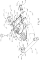
- Valve assembly (200) of the present example comprises a first valve (210) having a first axis (211), a second valve (300) having a second axis (302), which is parallel to first axis (211), shown in FIG. 4 .
- First valve (210) and second valve (300) are affixed in parallel alignment onto a valve frame (202).
- Valve frame (202) comprises a valve frame handle (203), a latch lever (204), a proximal end (206), and a distal end (208).
- latch lever (204) is cantileverly attached to valve frame (202) and is disposed between first valve (210) and second valve (300).
- Latch lever (204) includes a latching feature (205) and is resiliently biased such that when valve assembly (200) is inserted into receptacle (22) of control unit (20), latching feature (205) selectively secures valve assembly (200) to receptacle (22), as noted above.
- latching feature (205) selectively secures valve assembly (200) to receptacle (22), as noted above.
- other securing features may be used to selectively couple valve assembly (200) to control unit (20), such as adhesives, screws, bolts, clips, clamps, hook and loop connectors, etc.
- First valve (210) comprises a first valve spool (214) rotatably inserted into a first valve housing (212).
- first valve spool (214) comprises a cylindrical member having a first valve portion (216), a second valve portion (220), a proximal end (224), and a key slot (228) located within proximal end (224) of first valve spool (214).
- a pair of o-rings (230) are located between first valve portion (216) and second valve portion (220) and between second valve portion (220) and proximal end (224).
- o-rings (230) substantially seal each valve portion (216, 220) within valve housing (212) and also fluidly isolates each valve portion (216, 220) from the other valve portion (216, 220). It should be understood that the distal end of valve housing (212) is fluidly coupled and sealed to first tube (102) such that first valve portion (216) is fluidly sealed by o-ring (230) when first valve spool (214) is inserted into first valve housing (212).
- First valve spool (214) further includes an indicator (226), shown in FIG. 4 , extending radially outward at the proximal end of first valve spool (214) and indicates the orientation of hole (218), described in greater detail below.
- First valve housing (212) comprises a hollow cylindrical member that is coupled to and in fluid communication with a first connector (240), a second connector (246), a first vent connector (250), and saline connector (190).
- second connector (246) and saline connector (190) lie in a plane that is offset, but parallel to a vertical plane containing first axis (211).
- first valve spool (214) may selectively block both second connector (246) and saline connector (190) or may permit fluid communication between both second connector (246) and saline connectors (190), as will be described in more detail below.
- a first vent (252) is fluidly coupled to first vent connector (250).
- First vent (252) of the present example includes a semi-permeable filter mesh capable of allowing atmospheric air into and out of first vent connector (250).
- first valve portion (216) comprises a hollow cylindrical member having an open distal end (217) and a transverse hole (218). Hole (218) is configured to selectively align with first connector (240) of first valve housing (212), with first vent connector (250), and/or to substantially fluidly isolate the interior of first valve portion (216) depending upon the orientation of first valve spool (214). Accordingly, when an actuator (24) is coupled to key slot (228), actuator (24) is able to control the orientation of hole (218) relative to first connector (240), first vent connector (250), and/or otherwise. Thus, actuator (24) is operable to control whether first valve (210) vents first tube (102) to atmosphere via first vent (252) or supplies vacuum to first tube (102) via tubular member (150) and fourth tube (130).
- Second valve portion (220) comprises an axial hemi-cylindrical portion (222), shown best in FIG. 4 , such that an opposing hemi-cylindrical space is formed within first valve housing (212).
- hemi-cylindrical portion (222) is configured to selectively align such that second connector (246) and saline connector (190) are in fluid communication, or to substantially fluidly isolate second connector (246) relative to saline connector (190) depending upon the orientation of first valve spool (214). Accordingly, when an actuator (24) is coupled to key slot (228), actuator (24) is able to control the orientation of hemi-cylindrical portion (222) relative to second connector (246) and saline connector (190).
- actuator (24) is operable to control whether first valve (210) fluidly couples fifth tube (140) to saline connector (190) that is in fluid communication with third tube (106) and saline bag (50).
- first valve (210) fluidly couples fifth tube (140) to saline connector (190) that is in fluid communication with third tube (106) and saline bag (50).
- Second valve (300) comprises a second valve spool (314) rotatably inserted into a first valve housing (312).
- second valve spool (314) comprises a cylindrical member having a first valve portion (316), a proximal end (324), and a key slot (328) located within proximal end (324) of second valve spool (314).
- An o-ring (330) is located between first valve portion (316) and proximal end (324). In the present example, o-ring (330) substantially seals first valve portion (316) within valve housing (312) and also fluidly isolates first valve portion (316) from proximal end (324).
- valve housing (312) is fluidly coupled and sealed to second tube (104) such that first valve portion (316) is fluidly sealed by o-ring (330) when second valve spool (314) is inserted into second valve housing (312).
- Second valve spool (314) further includes an indicator (326) extending radially outward at the proximal end of second valve spool (314) and indicates the orientation of hole (318), described in greater detail below. It should be understood that indicator (326) is merely optional and may be omitted.
- Second valve housing (312) comprises a hollow cylindrical member that is coupled to and in fluid communication with a connector (340) and a second vent connector (350).
- a second vent (352) is fluidly coupled to second vent connector (350).
- Second vent (352) includes a semi-permeable filter mesh capable of allowing atmospheric air into and out of second vent connector (350).
- first valve portion (316) comprises a hollow cylindrical member having an open distal end (317) and a transverse hole (318). Hole (318) is configured to selectively align with connector (340) of second valve housing (312), with second vent connector (350), and/or to substantially fluidly isolate the interior of first valve portion (316) depending upon the orientation of second valve spool (314). Accordingly, when an actuator (24) is coupled to key slot (328), actuator (24) is able to control the orientation of hole (318) relative to connectors (340), second vent connector (350), and/or otherwise. Thus, actuator (24) is operable to control whether second valve (300) vents second tube (104) to atmosphere via second vent (352) or supplies vacuum to second tube (104) via tubular member (150) and fourth tube (130).
- valve frame (202), first valve (210), second valve (300), latch lever (204), and valve handle (203) may be made from a medical grade, rigid, injection molded plastic such as polycarbonate. All of the fluid carrying tubes described for valve assembly (200) (including first tube (102), second tube (104), third tube (106), fourth tube (130), and/or fifth tube (150)) may be made of an economical, flexible, medical grade material such as polyvinyl chloride (PVC).
- First valve spool (214) and second valve spool (314) are preferably made from a rigid, medical grade plastic such as polyethylene.
- valve assembly (200) when valve assembly (200) is to be correctly inserted into valve assembly receptacle (22) such that actuators (24) align with and couple to valve spools (214, 314), first axis (202) is aligned with the first cylindrical receptacle and second axis (302) is aligned with the second cylindrical receptacle, as described above.
- first valve (210) and second valve (300) are described as rotary valves, other types of valves may be used as will be apparent to one of ordinary skill in the art in view of the teachings herein.
- first valve (210) and second valve (300) are controlled via actuators (24) for different operational states.
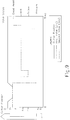
- FIG. 7 depicts an exemplary operational process showing the states of first valve (210) and second valve (300) relative to the position of cutter (50) and time. This operational process may constitute a single cutting stroke of cutter (50) to acquire a single tissue sample, and may be repeated as many times as desired to obtain as many tissue samples as desired.
- both first valve (210) and second valve (300) are in a "dead head" or sealed state such that no fluid is provided through tubes (102, 104, 106).
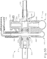
- first valve spool (214) is rotated such that hole (218) is not aligned with either first connector (240) or first vent connector (250), as shown in FIG. 5A , such that first tube (102) is not in fluid communication with either vent (252) or fourth tube (130).
- first valve spool (214) is oriented such that hemi-cylindrical section (222) substantially blocks fluid transfer from second connector (246) to saline connector (190) such that saline from saline bag (50) is not delivered to third tube (106). It should be understood that the cross-sectional view shown in FIG. 5A is set off from axis (202) to show connectors (190, 246) that are axially offset, as noted above.
- valve assembly unit (100) provides substantially no fluids to biopsy device (10).
- both valves (210, 300) begin in this state with cutter (50) advanced to position 1 such that lateral aperture (34) of needle (16) is closed.
- both first valve (210) and second valve (300) are in a vacuum state such that a negative (vacuum) pressure is provided through first tube (102) and second tube (104).
- first valve spool (214) is rotated by a corresponding actuator (24) such that hole (218) is aligned with first connector (240) of first valve housing (212), as shown in FIG. 5B .
- vacuum from fourth tube (130) is in fluid communication with first tube (102) such that a lateral vacuum is supplied to second lumen (38) of biopsy device (10).
- first valve spool (214) is positioned such that saline connectors (190) is not in fluid communication with second connector (246) of first valve housing (212). Accordingly, saline from saline bag (50) and fifth tube (140) is not in fluid communication with third tube (106). Also in this state, second valve spool (314) is rotated by a corresponding actuator (24) such that hole (318) is aligned with connector (340) of second valve housing (312), as shown in FIG. 6B . Accordingly, vacuum from fourth tube (130) is also in fluid communication with second tube (104) such that an axial vacuum is supplied to cutter lumen (52) of biopsy device (10).
- both valves (210, 300) are rotated into this state as cutter (50) is retracted to open lateral aperture (34) of needle (16). Both valves (210, 300) remain in this state such that tissue may be drawn into lateral aperture (34) of needle (16) of biopsy device (10) after cutter (50) is retracted and for a predetermined period as cutter (50) is advanced to sever the tissue.
- first valve (210) is rotated to a vent position such that an atmospheric pressure is provided through first tube (102) while second valve (300) remains in a vacuum state such that a negative (vacuum) pressure is provided second tube (104).
- first valve spool (214) is rotated by a corresponding actuator (24) such that hole (218) is aligned with first vent connector (250) such that first tube (102) is in fluid communication with first vent (252), as shown in FIG. 5C .
- hemi-cylindrical member (222) of first valve spool (214) is positioned such that saline connector (190) is not in fluid communication with second connector (246) of first valve housing (212).
- saline from saline bag (50) and fifth tube (140) is not in fluid communication with third tube (106).
- second valve spool (314) remains in the position shown in FIG. 6B and described above such that an axial vacuum is provided through second tube (104).
- the severed tissue sample may continue to be drawn axially through biopsy device (10) towards tissue sample holder (18) or, in some versions, any tissue debris within needle (16) is cleared from therein via the axial vacuum.
- first valve (210) is rotated to a saline position such that saline is provided from saline bag (50) through first tube (102) while second valve (300) remains in a vacuum state such that a negative (vacuum) pressure is provided second tube (104).
- first valve spool (214) is rotated by a corresponding actuator (24) such that hemi-cylindrical portion (222) does not impede fluid flow from saline connector (190) to second connector (246) of first valve housing (212), as shown in FIG. 5D .
- saline from saline bag (50) and fifth tube (140) is in fluid communication biopsy device (10) via third tube (106).
- first valve spool (214) is positioned such that neither first connector (240) nor first vent connector (250) is in fluid communication with first tube (102).
- second valve spool (314) remains in the position shown in FIG. 6B and described above such that an axial vacuum is provided through second tube (104). Accordingly, the axial vacuum provided by second tube (104) is used in biopsy device (10) to draw saline through third tube (106) and to draw a severed tissue sample axially through biopsy device (10) towards tissue sample holder (18). In some versions this state may occur when cutter (50) of biopsy device (10) is between 70% closed, inclusive, and fully closed, inclusive.
- first valve spool (214) may be rotated between the third state that vents to atmosphere and the fourth state that provides saline to alternate the supply of atmospheric air and saline to second lumen (38) of needle (16) of biopsy device (10).
- the alternation of saline and atmospheric air may be used to help flush a severed tissue sample into tissue sample holder (18) and/or clear biopsy device (10) of debris.
- first valve (210) is rotated to the saline position once cutter (50) is fully closed for a predetermined period of time and then is rotated back to the vent position described above.
- first valve (210) is rotated to a vent position while second valve (300) is rotated to a vent position such that atmospheric pressure is provided to both first tube (102) and second tube (104).
- first valve spool (214) is rotated to the position shown in FIG. 5D and described above.
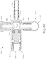
- Second valve spool (314) is rotated by a corresponding actuator (24) such that hole (318) is aligned with second vent connector (350) of second valve housing (312) such that second tube (104) is in fluid communication with second vent (352), as shown in FIG. 6C .
- biopsy device (10) and tubes (102, 104) are vented to atmosphere to remove residual pressure therein.
- first valve (210) and second valve (300) may be rotated back to the first state, the "dead head” state, described above, prior to a new biopsy procedure. For example, as shown in FIG. 7 , both first valve (210) and second valve (300) are rotated to the vent positions to relieve residual pressure followed by rotating to the "dead head” state.
- first valve (210) may be rotated to a saline position while second valve (300) is rotated to a vent position such that an atmospheric pressure is provided through second tube (104).
- first valve spool (214) remains in the saline state described above and shown in FIG. 5C .
- Second valve spool (314) is rotated to the vent position as shown and described in reference to FIG. 6C . Accordingly, saline is provided to biopsy device (10) without providing axial vacuum.
- T-valve (112) may be operated to provide medicaments from a source coupled to luer connector (114) while second tube (104) is vented.
- a state is merely optional.
- a marker applier may be inserted through cutter lumen (52) of cutter (50) to position the marker applier adjacent to lateral aperture (34) within needle (16). With cutter (50) in a retracted position, the user may expel a marker from the marker applier and through lateral aperture (34) of needle (16) for deployment at the biopsy site.
- the marker may be later visible (or may carry something that is later visible) under some sort of imaging modality (e.g., X-ray, ultrasound, MRI, PEM, BSGI, etc.), enabling a physician to later relocate the biopsy site.
- the marker and/or marker applier may be constructed in accordance with at least some of the teachings of U.S. Application Serial No. 13/205,189 , entitled “Access Chamber and Markers for Biopsy Device,” filed on August 8, 2011, the disclosure of which is incorporated by reference herein; and/or U.S. Application Serial No. 61/727,889 , entitled “Biopsy System with Graphical User Interface,” filed on November 19, 2012, the disclosures of which are incorporated by reference herein.
- tissue sample holder (18) remains coupled with probe (12) when the marker applier is inserted.
- tissue sample holder (18) may comprise multiple chambers for receiving tissue samples severed by cutter (50) and may have a dedicated chamber to receive a marker applier.
- the dedicated chamber of tissue sample holder (18) may be aligned with cutter (50) such that the marker applier may be inserted distally through the dedicated chamber of tissue sample holder (18) and through cutter lumen (52) of cutter (50).
- the user may first remove tissue sample holder (18) from probe (12), then insert the marker applier through the proximal end of cutter (50) until the marker applier reaches the longitudinal position associated with lateral aperture (34).
- a new pneumatic state may be activated when the dedicated chamber of tissue sample holder (18) is indexed to cutter lumen (52) and/or or when tissue sample holder (18) is removed from probe (12) to deploy a marker at the biopsy site.
- valve assembly (200) may be actuated in accordance with FIG. 8 , showing an exemplary operational process of the states of first valve (210) and second valve (300) relative to cutter (50) position and time.
- first valve (210) and second valve (300) are in a "dead head” after a tissue sample has been taken with biopsy device (10).
- first valve spool (214) is rotated such that hole (218) is not aligned with either first connector (240) or first vent connector (250), as shown in FIG. 5A , such that first tube (102) is not in fluid communication with either vent (252) or fourth tube (130).
- first valve spool (214) is oriented such that hemi-cylindrical section (222) substantially blocks fluid transfer from second connector (246) to saline connector (190) such that saline from saline bag (50) is not delivered to third tube (106).
- second valve spool (314) is rotated such that hole (318) is not aligned with either connector (340) or second vent connector (350), as shown in FIG. 6A , such that second tube (104) is not in fluid communication with either vent (352) or fourth tube (130).
- valve assembly unit (100) provides substantially no fluids to biopsy device (10).
- both valves (210, 300) are in this state with cutter (50) advanced to position 1 such that lateral aperture (34) of needle (16) is closed.
- first valve (210) is in a vacuum state and second valve (300) is in a vent state.
- first valve spool (214) is rotated by a corresponding actuator (24) such that hole (218) is aligned with first connector (240) of first valve housing (212), as shown in FIG. 5B .
- vacuum from fourth tube (130) is in fluid communication with first tube (102) such that a lateral vacuum is supplied to second lumen (38) of needle (16) of biopsy device (10).
- hemi-cylindrical portion (222) of first valve spool (214) is positioned such that saline connector (190) is not in fluid communication with second connector (246) of first valve housing (212).
- second valve spool (314) is rotated by a corresponding actuator (24) such that hole (318) is aligned with second vent connector (350) of second valve housing (312) such that second tube (104) is in fluid communication with second vent (352), as shown in FIG. 6C .
- atmospheric air is supplied to cutter lumen (52) of cutter (50) such that axial venting is provided to biopsy device (10).
- both valves (210, 300) are rotated into this state as cutter (50) is retracted to open lateral aperture (34) of needle (16).
- Both valves (210, 300) remain in this state such that a marker may be deployed to the biopsy site through lateral aperture (34) of needle (16) of biopsy device (10) after cutter (50) is retracted. Cutter (50) may then be advanced to reclose lateral aperture (34) of needle (16).
- first valve (210) is rotated to a vent position while second valve (300) remains at a vent position such that atmospheric pressure is provided to both first tube (102) and second tube (104).
- first valve spool (214) is rotated to the position shown in FIG. 5D and described above.
- Second valve spool (314) maintains the venting position such that hole (318) is aligned with second vent connector (350) of second valve housing (312) such that second tube (104) is in fluid communication with second vent (352), as shown in FIG. 6C .
- biopsy device (10) and tubes (102, 104) are vented to atmosphere to remove residual pressure therein.
- first valve (210) and second valve (300) may be rotated back to the first state, the "dead head” state, described above, prior to a new biopsy sample acquisition. For example, as shown in FIG. 8 , both first valve (210) and second valve (300) are rotated to the vent positions to relieve residual pressure followed by rotating to the "dead head” state.
- a clear probe algorithm may be initiated if tissue is jammed in cutter lumen (52) of cutter (50).
- an operator may determine that tissue is jammed in cutter lumen (52) if the operator completes a full cutting stroke with cutter (50) (e.g., in accordance with the process depicted in FIG. 7 ), yet a severed tissue sample does not appear within tissue sample holder (18).
- both first valve (210) and second valve (300) are in a "dead head" state during retraction and advancement of cutter (50) such that no fluid is provided through tubes (102, 104, 106).
- first valve spool (214) is rotated such that hole (218) is not aligned with either first connector (240) or first vent connector (250), as shown in FIG. 5A , such that first tube (102) is not in fluid communication with either vent (252) or fourth tube (130).
- first valve spool (214) is oriented such that hemi-cylindrical section (222) substantially blocks fluid transfer from second connector (246) to saline connector (190) such that saline from saline bag (50) is not delivered to third tube (106).
- second valve spool (314) is rotated such that hole (318) is not aligned with either connector (340) or second vent connector (350), as shown in FIG.
- valve assembly unit (100) provides substantially no fluids to biopsy device (10).
- cutter (50) is only retracted slightly before advancing again, as shown in FIG. 9 . In some instances, the retraction of cutter (50) is so slight that cutter (50) will not sever an additional tissue sample as it is advanced again. In other words, cutter (50) does not effectively open lateral aperture (34) of needle (16) enough to allow tissue to protrude into lateral aperture (34) for severing by cutter (50).
- first valve (210) is rotated to a vent position such that an atmospheric pressure is provided through first tube (102) while second valve (300) is rotated to a vacuum state such that a negative (vacuum) pressure is provided second tube (104).
- first valve spool (214) is rotated by a corresponding actuator (24) such that hole (218) is aligned with first vent connector (250) such that first tube (102) is in fluid communication with first vent (252), as shown in FIG. 5C .
- Second valve spool (314) remains in the position shown in FIG. 6B and described above such that an axial vacuum is provided through second tube (104).
- the previously severed tissue sample may continue to be drawn axially through biopsy device (10) towards tissue sample holder (18) or, in some versions, any tissue debris within needle (16) is cleared from therein via the axial vacuum.
- First valve (210) is then rotated to a saline position such that saline is provided from saline bag (50) through first tube (102) while second valve (300) remains in a vacuum state such that a negative (vacuum) pressure is provided second tube (104).
- first valve spool (214) is rotated by a corresponding actuator (24) such that hemi-cylindrical portion (222) does not impede fluid flow from saline connector (190) to second connector (246) of first valve housing (212), as shown in FIG. 5D .
- saline from saline bag (50) and fifth tube (140) is in fluid communication biopsy device (10) via third tube (106).
- second valve spool (314) remains in the position shown in FIG. 6B and described above such that an axial vacuum is provided through second tube (104). Accordingly, the axial vacuum provided by second tube (104) is used in biopsy device (10) to draw saline through third tube (106) and to draw a severed tissue sample axially through cutter lumen (52) toward tissue sample holder (18). As shown in FIG. 9 , first valve spool (214) may be rotated back to venting to atmosphere to alternate the supply of atmospheric air and saline to second lumen (38) of needle (16) of biopsy device (10). The alternation of saline and atmospheric air may be used to help flush a severed tissue sample into tissue sample holder (18) and/or clear biopsy device (10) of debris.
- First valve (210) then remains in a vent position while second valve (300) is rotated to a vent position such that atmospheric pressure is provided to both first tube (102) and second tube (104).
- first valve spool (214) is in the position shown in FIG. 5D and described above.
- Second valve spool (314) is rotated by a corresponding actuator (24) such that hole (318) is aligned with second vent connector (350) of second valve housing (312) such that second tube (104) is in fluid communication with second vent (352), as shown in FIG. 6C .
- biopsy device (10) and tubes (102, 104) are vented to atmosphere to remove residual pressure therein.
- first valve (210) and second valve (300) may be rotated back to the first state, the "dead head” state, described above, prior to a new biopsy sample acquisition. For example, as shown in FIG. 9 , both first valve (210) and second valve (300) are rotated to the vent positions to relieve residual pressure followed by rotating to the "dead head” state.
- Embodiments of the present invention have application in conventional endoscopic and open surgical instrumentation as well as application in robotic-assisted surgery.
- Embodiments of the devices disclosed herein can be designed to be disposed of after a single use, or they can be designed to be used multiple times. Embodiments may, in either or both cases, be reconditioned for reuse after at least one use. Reconditioning may include any combination of the steps of disassembly of the device, followed by cleaning or replacement of particular pieces, and subsequent reassembly. In particular, embodiments of the device may be disassembled, and any number of the particular pieces or parts of the device may be selectively replaced or removed in any combination. Upon cleaning and/or replacement of particular parts, embodiments of the device may be reassembled for subsequent use either at a reconditioning facility, or by a surgical team immediately prior to a surgical procedure.
- reconditioning of a device may utilize a variety of techniques for disassembly, cleaning/replacement, and reassembly. Use of such techniques, and the resulting reconditioned device, are all within the scope of the present application.
- a new or used instrument may be obtained and if necessary cleaned.
- the instrument may then be sterilized.
- the instrument is placed in a closed and sealed container, such as a plastic or TYVEK bag.
- the container and instrument may then be placed in a field of radiation that can penetrate the container, such as gamma radiation, x-rays, or high-energy electrons.
- the radiation may kill bacteria on the instrument and in the container.
- the sterilized instrument may then be stored in the sterile container.
- the sealed container may keep the instrument sterile until it is opened in a medical facility.
- a device may also be sterilized using any other technique known in the art, including but not limited to beta or gamma radiation, ethylene oxide, or steam.
Landscapes
- Health & Medical Sciences (AREA)
- Life Sciences & Earth Sciences (AREA)
- Heart & Thoracic Surgery (AREA)
- Surgery (AREA)
- General Health & Medical Sciences (AREA)
- Engineering & Computer Science (AREA)
- Veterinary Medicine (AREA)
- Biomedical Technology (AREA)
- Public Health (AREA)
- Animal Behavior & Ethology (AREA)
- Molecular Biology (AREA)
- Pathology (AREA)
- Medical Informatics (AREA)
- Nuclear Medicine, Radiotherapy & Molecular Imaging (AREA)
- Pulmonology (AREA)
- Anesthesiology (AREA)
- Hematology (AREA)
- Surgical Instruments (AREA)
Claims (15)
- Biopsieanordnung, umfassend:(a) eine Biopsievorrichtung (10), wobei die Biopsievorrichtung das Folgende aufweist:(i) einen Körper,(ii) eine Nadel (16), die sich distal vom Körper erstreckt, wobei die Nadel (16) eine seitliche Gewebeaufnahmeöffnung (34) definiert, und(iii) eine Schneidvorrichtung (50), die bezüglich der Nadel (16) verschiebbar ist, wobei die Schneidvorrichtung (50) dazu ausgelegt ist, die seitliche Gewebeaufnahmeöffnung (34) der Nadel (16) selektiv zu verschließen;(b) eine Vakuumquelle (26);(c) eine Quelle von Kochsalzlösung (50); und(d) eine Ventilanordnung (200) in Fluidverbindung mit der Nadel (16) der Biopsievorrichtung, wobei die Ventilanordnung das Folgende aufweist:(i) ein erstes Ventil (210), das zur selektiven Bereitstellung von atmosphärischer Entlüftung zur Nadel (16) bedienbar ist, wobei das erste Ventil (210) ferner zur selektiven Bereitstellung von Vakuum zur Nadel (16) bedienbar ist,(ii) ein zweites Ventil (300), das zur selektiven Bereitstellung von atmosphärischer Entlüftung zur Nadel (16) bedienbar ist, wobei das zweite Ventil (300) zur selektiven Bereitstellung von Vakuum zur Nadel (16) bedienbar ist, und(iii) ein röhrenförmiges Element (150), wobei das röhrenförmige Element (150) einen ersten Leitungskanal (130), der mit der Vakuumquelle (26) verbunden ist, und einen zweiten Leitungskanal (140), der mit der Quelle von Kochsalzlösung (50) verbunden ist, aufweist, wobei der erste Leitungskanal ein erstes Verbindungsglied (154) und ein zweites Verbindungsglied (156) aufweist, wobei das erste Verbindungsglied (154) mit dem ersten Ventil (210) verbunden ist und das zweite Verbindungsglied (156) mit dem zweiten Ventil (300) verbunden ist, so dass sich der erste Leitungskanal (130) zwischen den ersten und zweiten Ventilen (210, 300) durch die ersten und zweiten Verbindungsglieder (154, 156) erstreckt, wobei der erste Leitungskanal (130) zur Bereitstellung von Vakuum zu den ersten und zweiten Ventilen (210, 300) bedienbar ist, wobei der zweite Leitungskanal (140) ein drittes Verbindungsglied (162) aufweist, das mit dem ersten Ventil (210) verbunden ist, wobei der zweite Leitungskanal (140) zur Bereitstellung von Kochsalzlösung (50) zum ersten Ventil (210) bedienbar ist.
- Biopsieanordnung nach Anspruch 1, wobei die Nadel (16) ein erstes Lumen (36) und ein zweites Lumen (38) definiert, wobei die Schneidvorrichtung (50) innerhalb des ersten Lumens (36) der Nadel (16) verschiebbar ist, wobei die Schneidvorrichtung (50) ein Schneidvorrichtungslumen (52) definiert.
- Biopsieanordnung nach Anspruch 2, wobei das erste Ventil (210) mit dem zweiten Lumen (38) der Nadel (16) in Fluidverbindung steht und das zweite Ventil (300) mit dem Schneidvorrichtungslumen (52) der Schneidvorrichtung (50) in Fluidverbindung steht.
- Biopsieanordnung nach Anspruch 3, wobei die Ventilanordnung (200) ein erstes Betätigungsglied (24), das mit dem ersten Ventil (210) verbunden ist, und ein zweites Betätigungsglied (24), das mit dem zweiten Ventil (300) verbunden ist, aufweist.
- Biopsieanordnung nach Anspruch 4, wobei die ersten und zweiten Betätigungsglieder (24) dazu ausgelegt sind, die ersten und zweiten Ventile (210, 300) als Reaktion auf die Position der Schneidvorrichtung (50) zu betätigen.
- Biopsieanordnung nach Anspruch 5, wobei die ersten und zweiten Ventile (210, 300) dazu ausgelegt sind, abgedichtet zu werden, wenn die Schneidvorrichtung (50) positioniert wird, um die seitliche Gewebeaufnahmevorrichtung (34) im Wesentlichen zu verschließen.
- Biopsieanordnung nach Anspruch 5, wobei die ersten und zweiten Ventile (210, 300) dazu ausgelegt sind, Vakuum zur Nadel (16) bereitzustellen, wenn die Schneidvorrichtung (50) verschoben wird, um die seitliche Gewebeaufnahmeöffnung (34) im Wesentlichen zu öffnen.
- Biopsieanordnung nach Anspruch 5, wobei die Schneidvorrichtung (50) dazu ausgelegt ist, von einer offenen Stellung in eine geschlossene Stellung verschoben zu werden, wobei die Schneidvorrichtung (50) dazu ausgelegt ist, die seitliche Gewebeaufnahmevorrichtung (34) in der geschlossenen Stellungen im Wesentlichen zu verschließen.
- Biopsieanordnung nach Anspruch 8, wobei das erste Ventil (210) dazu ausgelegt ist, Entlüftung zur Nadel (16) bereitzustellen, wenn die Schneidvorrichtung (50) in die geschlossene Stellung verschoben wird, wobei das zweite Ventil (300) dazu ausgelegt ist, Vakuum zur Nadel (16) bereitzustellen, wenn die Schneidvorrichtung (50) in die geschlossene Stellung verschoben wird.
- Biopsieanordnung nach Anspruch 9, wobei das erste Ventil (210) zur selektiven Bereitstellung von Kochsalzlösung zum zweiten Lumen (38) der Nadel (16) bedienbar ist, wenn die Schneidvorrichtung (50) in die geschlossene Stellung verschoben wird, wobei das zweite Ventil (300) zur Bereitstellung von Vakuum zum Schneidvorrichtungslumen (52) der Schneidvorrichtung (50) ausgelegt ist, wenn die Schneidvorrichtung (50) in die geschlossene Stellung verschoben wird.
- Biopsieanordnung nach Anspruch 8, wobei die ersten und zweiten Ventile (210, 300) dazu ausgelegt sind, Entlüftung zur Nadel (16) bereitzustellen, wenn die Schneidvorrichtung (50) in die geschlossene Stellung verschoben wird.
- Biopsieanordnung nach Anspruch 8, wobei das erste Ventil (210) dazu ausgelegt ist, Vakuum zur Nadel (16) bereitzustellen, wenn die Schneidvorrichtung (50) zum Öffnen der seitlichen Gewebeaufnahmevorrichtung (34) verschoben wird, wobei das zweite Ventil (300) dazu ausgelegt ist, Entlüftung zur Nadel (16) bereitzustellen, wenn die Schneidvorrichtung (50) zum Öffnen der seitlichen Gewebeaufnahmevorrichtung (34) verschoben wird.
- Biopsieanordnung nach Anspruch 1, wobei die Ventilanordnung (200) einen Luer-Verbinder (108, 110, 116) aufweist, wobei der Luer-Verbinder (108, 110, 116) bedienbar ist, um die Ventilanordnung (200) selektiv mit der Biopsievorrichtung (10) zu verbinden.
- Biopsieanordnung nach Anspruch 1, ferner umfassend eine Steuereinheit (20), wobei die Steuereinheit (20) zur Betätigung der Ventilanordnung (200) bedienbar ist.
- Biopsieanordnung nach Anspruch 14, wobei die Steuereinheit (20) eine Ventilanordnungsaufnahme (22) aufweist, wobei die Ventilanordnungsaufnahme (22) zur Aufnahme eines proximalen Endes der Ventilanordnung (200) ausgelegt ist.
Priority Applications (1)
| Application Number | Priority Date | Filing Date | Title |
|---|---|---|---|
| PL13749571T PL2814399T3 (pl) | 2012-02-15 | 2013-02-13 | Zespół zaworowy urządzenia do biopsji |
Applications Claiming Priority (2)
| Application Number | Priority Date | Filing Date | Title |
|---|---|---|---|
| US201261598939P | 2012-02-15 | 2012-02-15 | |
| PCT/US2013/025853 WO2013122992A1 (en) | 2012-02-15 | 2013-02-13 | Biopsy device valve assembly |
Publications (3)
| Publication Number | Publication Date |
|---|---|
| EP2814399A1 EP2814399A1 (de) | 2014-12-24 |
| EP2814399A4 EP2814399A4 (de) | 2015-10-14 |
| EP2814399B1 true EP2814399B1 (de) | 2018-04-04 |
Family
ID=48982802
Family Applications (1)
| Application Number | Title | Priority Date | Filing Date |
|---|---|---|---|
| EP13749571.9A Active EP2814399B1 (de) | 2012-02-15 | 2013-02-13 | Ventilanordnung für eine biopsievorrichtung |
Country Status (8)
| Country | Link |
|---|---|
| US (1) | US9724076B2 (de) |
| EP (1) | EP2814399B1 (de) |
| JP (1) | JP6169622B2 (de) |
| KR (2) | KR102210308B1 (de) |
| CN (1) | CN104039239B (de) |
| CA (1) | CA2864528A1 (de) |
| PL (1) | PL2814399T3 (de) |
| WO (1) | WO2013122992A1 (de) |
Families Citing this family (35)
| Publication number | Priority date | Publication date | Assignee | Title |
|---|---|---|---|---|
| US20140039343A1 (en) | 2006-12-13 | 2014-02-06 | Devicor Medical Products, Inc. | Biopsy system |
| EP2967510B1 (de) | 2013-03-15 | 2019-07-24 | Devicor Medical Products, Inc. | Biopsievorrichtung |
| KR102275365B1 (ko) | 2013-05-07 | 2021-07-12 | 데비코어 메디컬 프로덕츠, 인코포레이티드 | 생검 디바이스용 바늘 발사 어셈블리 |
| CN114748108A (zh) | 2013-08-28 | 2022-07-15 | 德威科医疗产品公司 | 用于活检装置的组织收集总成 |
| US10206665B2 (en) * | 2013-11-25 | 2019-02-19 | Devicor Medical Products, Inc. | Biopsy device with translating valve assembly |
| KR101649713B1 (ko) * | 2014-04-10 | 2016-08-19 | 주식회사 메디칼파크 | 생체 검사 장치 및 시스템 |
| US10610205B2 (en) | 2014-05-15 | 2020-04-07 | Devicor Medical Products, Inc. | Biopsy device |
| US10201333B2 (en) | 2014-09-24 | 2019-02-12 | Devicor Medical Products, Inc. | MRI biopsy system |
| US9456808B2 (en) | 2014-09-25 | 2016-10-04 | Hologic, Inc. | Biopsy device with automatic biopsy parameter adjustment |
| EP3086715B1 (de) | 2014-09-25 | 2018-04-04 | Hologic Inc. | Biopsievorrichtung mit aspirationsventil |
| US10314563B2 (en) | 2014-11-26 | 2019-06-11 | Devicor Medical Products, Inc. | Graphical user interface for biopsy device |
| EP3291740A4 (de) * | 2015-06-02 | 2018-10-24 | Becton, Dickinson and Company | Gewebeentfernungsvorrichtung und verfahren zur verwendung |
| HK1254538A1 (zh) | 2015-10-30 | 2019-07-19 | Devicor Medical Products, Inc. | 具有批量组织收集特徵的组织样品保持器 |
| US10285669B2 (en) | 2016-07-01 | 2019-05-14 | Devicor Medical Products, Inc. | Biopsy sample container |
| JP2019519790A (ja) | 2016-07-01 | 2019-07-11 | デビコー・メディカル・プロダクツ・インコーポレイテッドDevicor Medical Products, Inc. | 乳房生検処置から得た組織試料の処置のための統合されたワークフロー優先権 |
| US10729856B1 (en) | 2016-07-29 | 2020-08-04 | Devicor Medical Products, Inc. | Guide and filter for biopsy device |
| KR102672534B1 (ko) | 2016-12-02 | 2024-06-07 | 데비코어 메디컬 프로덕츠, 인코포레이티드 | 생검 장치를 위한 다중 챔버 조직 샘플 컵 |
| JP6840852B2 (ja) | 2016-12-02 | 2021-03-10 | デビコー・メディカル・プロダクツ・インコーポレイテッドDevicor Medical Products, Inc. | 組織採取中の生検試料の可視化を可能にする装置 |
| US11504101B1 (en) | 2017-05-12 | 2022-11-22 | Devicor Medical Products, Inc. | Biopsy device with remote multi-chamber tissue sample holder |
| CN110573108B (zh) | 2017-05-12 | 2021-04-06 | Devicor医疗产业收购公司 | 带有尖端保护器和安装设备的活检装置 |
| CN110621234B (zh) | 2017-05-12 | 2024-10-25 | Devicor医疗产业收购公司 | 具有无菌套筒的活检装置 |
| US10610206B2 (en) * | 2017-08-09 | 2020-04-07 | Spiration, Inc. | Vacuum assisted sampling mechanism |
| CN117958872A (zh) | 2017-12-05 | 2024-05-03 | Devicor医疗产业收购公司 | 具有应用成像的活检装置 |
| JP7179870B2 (ja) * | 2018-04-18 | 2022-11-29 | シー・アール・バード・インコーポレーテッド | 一体化される組織マーカー送達装置を有するデュアルルーメン同軸イントロデューサ |
| JP7184929B2 (ja) | 2018-06-08 | 2022-12-06 | デビコー・メディカル・プロダクツ・インコーポレイテッド | 組織除去中の選択的な生検サンプルの可視化を可能にする装置 |
| US11202622B2 (en) | 2018-06-20 | 2021-12-21 | Devicor Medical Products, Inc. | Tissue sample holder with enhanced fluid management |
| EP4093295B1 (de) | 2020-03-04 | 2024-01-24 | Devicor Medical Products, Inc. | Schiebeverschluss für biopsievorrichtung |
| EP4482397A1 (de) | 2022-04-28 | 2025-01-01 | Devicor Medical Products, Inc. | Biopsievorrichtung mit integrierter zitterfunktion |
| WO2024077477A1 (en) | 2022-10-11 | 2024-04-18 | Devicor Medical Products, Inc. | Graphical user interface for biopsy device |
| WO2024091430A1 (en) | 2022-10-27 | 2024-05-02 | Devicor Medical Products, Inc. | Detection of calcification in a targeted breast biopsy tissue |
| JP2024095618A (ja) | 2022-12-28 | 2024-07-10 | デビコー・メディカル・プロダクツ・インコーポレイテッド | 磁気共鳴画像室で使用する生検システム |
| WO2025014629A1 (en) | 2023-07-07 | 2025-01-16 | Devicor Medical Products, Inc. | Tissue sample holder drive mechanisms for biopsy device |
| WO2025072146A1 (en) | 2023-09-28 | 2025-04-03 | Devicor Medical Products, Inc. | In-line tissue analysis and transportation method |
| WO2025072145A1 (en) | 2023-09-28 | 2025-04-03 | Devicor Medical Products, Inc. | Articulating imaging and sample collection unit |
| CN121925221A (zh) | 2023-09-28 | 2026-04-24 | Devicor医疗产业收购公司 | 具有在抽吸路径外进行在线样本成像的活检装置 |
Family Cites Families (29)
| Publication number | Priority date | Publication date | Assignee | Title |
|---|---|---|---|---|
| US5526822A (en) | 1994-03-24 | 1996-06-18 | Biopsys Medical, Inc. | Method and apparatus for automated biopsy and collection of soft tissue |
| US5649547A (en) * | 1994-03-24 | 1997-07-22 | Biopsys Medical, Inc. | Methods and devices for automated biopsy and collection of soft tissue |
| US6017316A (en) * | 1997-06-18 | 2000-01-25 | Biopsys Medical | Vacuum control system and method for automated biopsy device |
| CA2287087C (en) * | 1998-10-23 | 2007-12-04 | Ethicon Endo-Surgery, Inc. | Surgical device for the collection of soft tissue |
| US6120462A (en) * | 1999-03-31 | 2000-09-19 | Ethicon Endo-Surgery, Inc. | Control method for an automated surgical biopsy device |
| US6086544A (en) | 1999-03-31 | 2000-07-11 | Ethicon Endo-Surgery, Inc. | Control apparatus for an automated surgical biopsy device |
| US6162187A (en) * | 1999-08-02 | 2000-12-19 | Ethicon Endo-Surgery, Inc. | Fluid collection apparatus for a surgical device |
| US6602203B2 (en) | 2000-10-13 | 2003-08-05 | Ethicon Endo-Surgery, Inc. | Remote thumbwheel for a surgical biopsy device |
| US6626849B2 (en) | 2001-11-01 | 2003-09-30 | Ethicon Endo-Surgery, Inc. | MRI compatible surgical biopsy device |
| CN100453052C (zh) * | 2003-02-25 | 2009-01-21 | 伊西康内外科公司 | 具有变速前进切割器的活组织检查装置 |
| US7276032B2 (en) * | 2004-09-29 | 2007-10-02 | Ethicon Endo-Surgery, Inc. | Biopsy apparatus and method |
| US20060074345A1 (en) | 2004-09-29 | 2006-04-06 | Hibner John A | Biopsy apparatus and method |
| US7740596B2 (en) | 2004-09-29 | 2010-06-22 | Ethicon Endo-Surgery, Inc. | Biopsy device with sample storage |
| US7517322B2 (en) * | 2005-03-04 | 2009-04-14 | Ethicon Endo-Surgery, Inc. | Biopsy device with variable side aperture |
| US7662109B2 (en) * | 2006-02-01 | 2010-02-16 | Ethicon Endo-Surgery, Inc. | Biopsy device with replaceable probe incorporating static vacuum source dual valve sample stacking retrieval and saline flush |
| US7938786B2 (en) | 2006-12-13 | 2011-05-10 | Devicor Medical Products, Inc. | Vacuum timing algorithm for biopsy device |
| US9345457B2 (en) | 2006-12-13 | 2016-05-24 | Devicor Medical Products, Inc. | Presentation of biopsy sample by biopsy device |
| EP1932482B1 (de) * | 2006-12-13 | 2010-04-28 | Ethicon Endo-Surgery, Inc. | Biopsieprobenlagerung |
| US7575556B2 (en) | 2007-11-20 | 2009-08-18 | Ethicon Endo-Surgery, Inc. | Deployment device interface for biopsy device |
| US7854706B2 (en) | 2007-12-27 | 2010-12-21 | Devicor Medical Products, Inc. | Clutch and valving system for tetherless biopsy device |
| US20100152610A1 (en) | 2008-12-16 | 2010-06-17 | Parihar Shailendra K | Hand Actuated Tetherless Biopsy Device with Pistol Grip |
| US20100160819A1 (en) | 2008-12-18 | 2010-06-24 | Parihar Shailendra K | Biopsy Device with Central Thumbwheel |
| US8206316B2 (en) | 2009-06-12 | 2012-06-26 | Devicor Medical Products, Inc. | Tetherless biopsy device with reusable portion |
| US8529468B2 (en) * | 2009-07-01 | 2013-09-10 | Suros Surgical Systems, Inc. | Surgical system |
| US8764680B2 (en) | 2010-11-01 | 2014-07-01 | Devicor Medical Products, Inc. | Handheld biopsy device with needle firing |
| US8858465B2 (en) | 2011-04-14 | 2014-10-14 | Devicor Medical Products, Inc. | Biopsy device with motorized needle firing |
| US8801742B2 (en) | 2011-06-01 | 2014-08-12 | Devicor Medical Products, Inc. | Needle assembly and blade assembly for biopsy device |
| US8938285B2 (en) | 2011-08-08 | 2015-01-20 | Devicor Medical Products, Inc. | Access chamber and markers for biopsy device |
| US9326755B2 (en) | 2011-08-26 | 2016-05-03 | Devicor Medical Products, Inc. | Biopsy device tissue sample holder with bulk chamber and pathology chamber |
-
2013
- 2013-02-13 CN CN201380005246.1A patent/CN104039239B/zh active Active
- 2013-02-13 US US13/765,931 patent/US9724076B2/en active Active
- 2013-02-13 KR KR1020207010408A patent/KR102210308B1/ko active Active
- 2013-02-13 KR KR1020147025525A patent/KR102101924B1/ko active Active
- 2013-02-13 PL PL13749571T patent/PL2814399T3/pl unknown
- 2013-02-13 JP JP2014557735A patent/JP6169622B2/ja active Active
- 2013-02-13 CA CA2864528A patent/CA2864528A1/en not_active Abandoned
- 2013-02-13 WO PCT/US2013/025853 patent/WO2013122992A1/en not_active Ceased
- 2013-02-13 EP EP13749571.9A patent/EP2814399B1/de active Active
Non-Patent Citations (1)
| Title |
|---|
| None * |
Also Published As
| Publication number | Publication date |
|---|---|
| KR20140123103A (ko) | 2014-10-21 |
| KR20200042954A (ko) | 2020-04-24 |
| US20130218047A1 (en) | 2013-08-22 |
| JP6169622B2 (ja) | 2017-07-26 |
| CA2864528A1 (en) | 2013-08-22 |
| EP2814399A4 (de) | 2015-10-14 |
| KR102210308B1 (ko) | 2021-02-02 |
| CN104039239B (zh) | 2016-09-28 |
| EP2814399A1 (de) | 2014-12-24 |
| WO2013122992A1 (en) | 2013-08-22 |
| JP2015510435A (ja) | 2015-04-09 |
| PL2814399T3 (pl) | 2018-10-31 |
| CN104039239A (zh) | 2014-09-10 |
| KR102101924B1 (ko) | 2020-04-20 |
| US9724076B2 (en) | 2017-08-08 |
Similar Documents
| Publication | Publication Date | Title |
|---|---|---|
| US9724076B2 (en) | Biopsy device valve assembly | |
| US12114841B2 (en) | Apparatus to allow biopsy sample visualization during tissue removal | |
| US9326755B2 (en) | Biopsy device tissue sample holder with bulk chamber and pathology chamber | |
| EP3142565B1 (de) | Biopsievorrichtung | |
| CN113520482B (zh) | 用于活检装置的多腔室组织样品杯 | |
| CN113766880B (zh) | 具有集成真空储存器的活检装置 | |
| WO2017075415A1 (en) | Tissue sample holder with bulk tissue collection feature | |
| US12465337B2 (en) | Needle rotation mechanism for biopsy needle | |
| AU2015202544B2 (en) | Biopsy device tissue sample holder with bulk chamber and pathology chamber | |
| HK1199390B (en) | Biopsy device tissue sample holder with bulk chamber and pathology chamber |
Legal Events
| Date | Code | Title | Description |
|---|---|---|---|
| PUAI | Public reference made under article 153(3) epc to a published international application that has entered the european phase |
Free format text: ORIGINAL CODE: 0009012 |
|
| 17P | Request for examination filed |
Effective date: 20140915 |
|
| AK | Designated contracting states |
Kind code of ref document: A1 Designated state(s): AL AT BE BG CH CY CZ DE DK EE ES FI FR GB GR HR HU IE IS IT LI LT LU LV MC MK MT NL NO PL PT RO RS SE SI SK SM TR |
|
| AX | Request for extension of the european patent |
Extension state: BA ME |
|
| DAX | Request for extension of the european patent (deleted) | ||
| RA4 | Supplementary search report drawn up and despatched (corrected) |
Effective date: 20150916 |
|
| RIC1 | Information provided on ipc code assigned before grant |
Ipc: A61B 10/02 20060101AFI20150910BHEP |
|
| STAA | Information on the status of an ep patent application or granted ep patent |
Free format text: STATUS: EXAMINATION IS IN PROGRESS |
|
| 17Q | First examination report despatched |
Effective date: 20170127 |
|
| GRAP | Despatch of communication of intention to grant a patent |
Free format text: ORIGINAL CODE: EPIDOSNIGR1 |
|
| STAA | Information on the status of an ep patent application or granted ep patent |
Free format text: STATUS: GRANT OF PATENT IS INTENDED |
|
| INTG | Intention to grant announced |
Effective date: 20171011 |
|
| GRAS | Grant fee paid |
Free format text: ORIGINAL CODE: EPIDOSNIGR3 |
|
| GRAA | (expected) grant |
Free format text: ORIGINAL CODE: 0009210 |
|
| STAA | Information on the status of an ep patent application or granted ep patent |
Free format text: STATUS: THE PATENT HAS BEEN GRANTED |
|
| AK | Designated contracting states |
Kind code of ref document: B1 Designated state(s): AL AT BE BG CH CY CZ DE DK EE ES FI FR GB GR HR HU IE IS IT LI LT LU LV MC MK MT NL NO PL PT RO RS SE SI SK SM TR |
|
| REG | Reference to a national code |
Ref country code: GB Ref legal event code: FG4D |
|
| REG | Reference to a national code |
Ref country code: CH Ref legal event code: EP |
|
| REG | Reference to a national code |
Ref country code: AT Ref legal event code: REF Ref document number: 984681 Country of ref document: AT Kind code of ref document: T Effective date: 20180415 |
|
| REG | Reference to a national code |
Ref country code: DE Ref legal event code: R096 Ref document number: 602013035405 Country of ref document: DE |
|
| REG | Reference to a national code |
Ref country code: IE Ref legal event code: FG4D |
|
| REG | Reference to a national code |
Ref country code: NL Ref legal event code: MP Effective date: 20180404 |
|
| REG | Reference to a national code |
Ref country code: LT Ref legal event code: MG4D |
|
| PG25 | Lapsed in a contracting state [announced via postgrant information from national office to epo] |
Ref country code: NL Free format text: LAPSE BECAUSE OF FAILURE TO SUBMIT A TRANSLATION OF THE DESCRIPTION OR TO PAY THE FEE WITHIN THE PRESCRIBED TIME-LIMIT Effective date: 20180404 |
|
| PG25 | Lapsed in a contracting state [announced via postgrant information from national office to epo] |
Ref country code: ES Free format text: LAPSE BECAUSE OF FAILURE TO SUBMIT A TRANSLATION OF THE DESCRIPTION OR TO PAY THE FEE WITHIN THE PRESCRIBED TIME-LIMIT Effective date: 20180404 Ref country code: AL Free format text: LAPSE BECAUSE OF FAILURE TO SUBMIT A TRANSLATION OF THE DESCRIPTION OR TO PAY THE FEE WITHIN THE PRESCRIBED TIME-LIMIT Effective date: 20180404 Ref country code: SE Free format text: LAPSE BECAUSE OF FAILURE TO SUBMIT A TRANSLATION OF THE DESCRIPTION OR TO PAY THE FEE WITHIN THE PRESCRIBED TIME-LIMIT Effective date: 20180404 Ref country code: BG Free format text: LAPSE BECAUSE OF FAILURE TO SUBMIT A TRANSLATION OF THE DESCRIPTION OR TO PAY THE FEE WITHIN THE PRESCRIBED TIME-LIMIT Effective date: 20180704 Ref country code: FI Free format text: LAPSE BECAUSE OF FAILURE TO SUBMIT A TRANSLATION OF THE DESCRIPTION OR TO PAY THE FEE WITHIN THE PRESCRIBED TIME-LIMIT Effective date: 20180404 Ref country code: NO Free format text: LAPSE BECAUSE OF FAILURE TO SUBMIT A TRANSLATION OF THE DESCRIPTION OR TO PAY THE FEE WITHIN THE PRESCRIBED TIME-LIMIT Effective date: 20180704 Ref country code: LT Free format text: LAPSE BECAUSE OF FAILURE TO SUBMIT A TRANSLATION OF THE DESCRIPTION OR TO PAY THE FEE WITHIN THE PRESCRIBED TIME-LIMIT Effective date: 20180404 |
|
| PG25 | Lapsed in a contracting state [announced via postgrant information from national office to epo] |
Ref country code: GR Free format text: LAPSE BECAUSE OF FAILURE TO SUBMIT A TRANSLATION OF THE DESCRIPTION OR TO PAY THE FEE WITHIN THE PRESCRIBED TIME-LIMIT Effective date: 20180705 Ref country code: HR Free format text: LAPSE BECAUSE OF FAILURE TO SUBMIT A TRANSLATION OF THE DESCRIPTION OR TO PAY THE FEE WITHIN THE PRESCRIBED TIME-LIMIT Effective date: 20180404 Ref country code: LV Free format text: LAPSE BECAUSE OF FAILURE TO SUBMIT A TRANSLATION OF THE DESCRIPTION OR TO PAY THE FEE WITHIN THE PRESCRIBED TIME-LIMIT Effective date: 20180404 Ref country code: RS Free format text: LAPSE BECAUSE OF FAILURE TO SUBMIT A TRANSLATION OF THE DESCRIPTION OR TO PAY THE FEE WITHIN THE PRESCRIBED TIME-LIMIT Effective date: 20180404 |
|
| REG | Reference to a national code |
Ref country code: AT Ref legal event code: MK05 Ref document number: 984681 Country of ref document: AT Kind code of ref document: T Effective date: 20180404 |
|
| PG25 | Lapsed in a contracting state [announced via postgrant information from national office to epo] |
Ref country code: PT Free format text: LAPSE BECAUSE OF FAILURE TO SUBMIT A TRANSLATION OF THE DESCRIPTION OR TO PAY THE FEE WITHIN THE PRESCRIBED TIME-LIMIT Effective date: 20180806 |
|
| REG | Reference to a national code |
Ref country code: DE Ref legal event code: R097 Ref document number: 602013035405 Country of ref document: DE |
|
| PG25 | Lapsed in a contracting state [announced via postgrant information from national office to epo] |
Ref country code: RO Free format text: LAPSE BECAUSE OF FAILURE TO SUBMIT A TRANSLATION OF THE DESCRIPTION OR TO PAY THE FEE WITHIN THE PRESCRIBED TIME-LIMIT Effective date: 20180404 Ref country code: CZ Free format text: LAPSE BECAUSE OF FAILURE TO SUBMIT A TRANSLATION OF THE DESCRIPTION OR TO PAY THE FEE WITHIN THE PRESCRIBED TIME-LIMIT Effective date: 20180404 Ref country code: DK Free format text: LAPSE BECAUSE OF FAILURE TO SUBMIT A TRANSLATION OF THE DESCRIPTION OR TO PAY THE FEE WITHIN THE PRESCRIBED TIME-LIMIT Effective date: 20180404 Ref country code: AT Free format text: LAPSE BECAUSE OF FAILURE TO SUBMIT A TRANSLATION OF THE DESCRIPTION OR TO PAY THE FEE WITHIN THE PRESCRIBED TIME-LIMIT Effective date: 20180404 Ref country code: EE Free format text: LAPSE BECAUSE OF FAILURE TO SUBMIT A TRANSLATION OF THE DESCRIPTION OR TO PAY THE FEE WITHIN THE PRESCRIBED TIME-LIMIT Effective date: 20180404 Ref country code: SK Free format text: LAPSE BECAUSE OF FAILURE TO SUBMIT A TRANSLATION OF THE DESCRIPTION OR TO PAY THE FEE WITHIN THE PRESCRIBED TIME-LIMIT Effective date: 20180404 |
|
| PLBE | No opposition filed within time limit |
Free format text: ORIGINAL CODE: 0009261 |
|
| STAA | Information on the status of an ep patent application or granted ep patent |
Free format text: STATUS: NO OPPOSITION FILED WITHIN TIME LIMIT |
|
| PG25 | Lapsed in a contracting state [announced via postgrant information from national office to epo] |
Ref country code: SM Free format text: LAPSE BECAUSE OF FAILURE TO SUBMIT A TRANSLATION OF THE DESCRIPTION OR TO PAY THE FEE WITHIN THE PRESCRIBED TIME-LIMIT Effective date: 20180404 |
|
| 26N | No opposition filed |
Effective date: 20190107 |
|
| PG25 | Lapsed in a contracting state [announced via postgrant information from national office to epo] |
Ref country code: SI Free format text: LAPSE BECAUSE OF FAILURE TO SUBMIT A TRANSLATION OF THE DESCRIPTION OR TO PAY THE FEE WITHIN THE PRESCRIBED TIME-LIMIT Effective date: 20180404 |
|
| REG | Reference to a national code |
Ref country code: CH Ref legal event code: PL |
|
| PG25 | Lapsed in a contracting state [announced via postgrant information from national office to epo] |
Ref country code: LU Free format text: LAPSE BECAUSE OF NON-PAYMENT OF DUE FEES Effective date: 20190213 Ref country code: MC Free format text: LAPSE BECAUSE OF FAILURE TO SUBMIT A TRANSLATION OF THE DESCRIPTION OR TO PAY THE FEE WITHIN THE PRESCRIBED TIME-LIMIT Effective date: 20180404 |
|
| REG | Reference to a national code |
Ref country code: BE Ref legal event code: MM Effective date: 20190228 |
|
| REG | Reference to a national code |
Ref country code: IE Ref legal event code: MM4A |
|
| PG25 | Lapsed in a contracting state [announced via postgrant information from national office to epo] |
Ref country code: CH Free format text: LAPSE BECAUSE OF NON-PAYMENT OF DUE FEES Effective date: 20190228 Ref country code: LI Free format text: LAPSE BECAUSE OF NON-PAYMENT OF DUE FEES Effective date: 20190228 |
|
| PG25 | Lapsed in a contracting state [announced via postgrant information from national office to epo] |
Ref country code: IE Free format text: LAPSE BECAUSE OF NON-PAYMENT OF DUE FEES Effective date: 20190213 |
|
| PG25 | Lapsed in a contracting state [announced via postgrant information from national office to epo] |
Ref country code: BE Free format text: LAPSE BECAUSE OF NON-PAYMENT OF DUE FEES Effective date: 20190228 |
|
| PG25 | Lapsed in a contracting state [announced via postgrant information from national office to epo] |
Ref country code: TR Free format text: LAPSE BECAUSE OF FAILURE TO SUBMIT A TRANSLATION OF THE DESCRIPTION OR TO PAY THE FEE WITHIN THE PRESCRIBED TIME-LIMIT Effective date: 20180404 |
|
| PGFP | Annual fee paid to national office [announced via postgrant information from national office to epo] |
Ref country code: PL Payment date: 20200207 Year of fee payment: 8 |
|
| PG25 | Lapsed in a contracting state [announced via postgrant information from national office to epo] |
Ref country code: MT Free format text: LAPSE BECAUSE OF NON-PAYMENT OF DUE FEES Effective date: 20190213 |
|
| PG25 | Lapsed in a contracting state [announced via postgrant information from national office to epo] |
Ref country code: CY Free format text: LAPSE BECAUSE OF FAILURE TO SUBMIT A TRANSLATION OF THE DESCRIPTION OR TO PAY THE FEE WITHIN THE PRESCRIBED TIME-LIMIT Effective date: 20180404 |
|
| PG25 | Lapsed in a contracting state [announced via postgrant information from national office to epo] |
Ref country code: IS Free format text: LAPSE BECAUSE OF FAILURE TO SUBMIT A TRANSLATION OF THE DESCRIPTION OR TO PAY THE FEE WITHIN THE PRESCRIBED TIME-LIMIT Effective date: 20180804 |
|
| PG25 | Lapsed in a contracting state [announced via postgrant information from national office to epo] |
Ref country code: HU Free format text: LAPSE BECAUSE OF FAILURE TO SUBMIT A TRANSLATION OF THE DESCRIPTION OR TO PAY THE FEE WITHIN THE PRESCRIBED TIME-LIMIT; INVALID AB INITIO Effective date: 20130213 |
|
| PG25 | Lapsed in a contracting state [announced via postgrant information from national office to epo] |
Ref country code: MK Free format text: LAPSE BECAUSE OF FAILURE TO SUBMIT A TRANSLATION OF THE DESCRIPTION OR TO PAY THE FEE WITHIN THE PRESCRIBED TIME-LIMIT Effective date: 20180404 |
|
| PG25 | Lapsed in a contracting state [announced via postgrant information from national office to epo] |
Ref country code: PL Free format text: LAPSE BECAUSE OF NON-PAYMENT OF DUE FEES Effective date: 20210213 |
|
| P01 | Opt-out of the competence of the unified patent court (upc) registered |
Effective date: 20230525 |
|
| PGFP | Annual fee paid to national office [announced via postgrant information from national office to epo] |
Ref country code: GB Payment date: 20260223 Year of fee payment: 14 |
|
| PGFP | Annual fee paid to national office [announced via postgrant information from national office to epo] |
Ref country code: DE Payment date: 20260220 Year of fee payment: 14 |
|
| PGFP | Annual fee paid to national office [announced via postgrant information from national office to epo] |
Ref country code: IT Payment date: 20260220 Year of fee payment: 14 |
|
| PGFP | Annual fee paid to national office [announced via postgrant information from national office to epo] |
Ref country code: FR Payment date: 20260227 Year of fee payment: 14 |