EP2814562B1 - Doppelseitige elektrode mit gesteuertem stromfluss - Google Patents
Doppelseitige elektrode mit gesteuertem stromfluss Download PDFInfo
- Publication number
- EP2814562B1 EP2814562B1 EP13748855.7A EP13748855A EP2814562B1 EP 2814562 B1 EP2814562 B1 EP 2814562B1 EP 13748855 A EP13748855 A EP 13748855A EP 2814562 B1 EP2814562 B1 EP 2814562B1
- Authority
- EP
- European Patent Office
- Prior art keywords
- electrode
- slave
- field controlling
- conductive
- master
- Prior art date
- Legal status (The legal status is an assumption and is not a legal conclusion. Google has not performed a legal analysis and makes no representation as to the accuracy of the status listed.)
- Active
Links
Images


Classifications
-
- A—HUMAN NECESSITIES
- A61—MEDICAL OR VETERINARY SCIENCE; HYGIENE
- A61N—ELECTROTHERAPY; MAGNETOTHERAPY; RADIATION THERAPY; ULTRASOUND THERAPY
- A61N1/00—Electrotherapy; Circuits therefor
- A61N1/02—Details
- A61N1/04—Electrodes
- A61N1/0404—Electrodes for external use
- A61N1/0408—Use-related aspects
- A61N1/0452—Specially adapted for transcutaneous muscle stimulation [TMS]
-
- A—HUMAN NECESSITIES
- A61—MEDICAL OR VETERINARY SCIENCE; HYGIENE
- A61N—ELECTROTHERAPY; MAGNETOTHERAPY; RADIATION THERAPY; ULTRASOUND THERAPY
- A61N1/00—Electrotherapy; Circuits therefor
- A61N1/02—Details
- A61N1/04—Electrodes
- A61N1/0404—Electrodes for external use
- A61N1/0408—Use-related aspects
- A61N1/0456—Specially adapted for transcutaneous electrical nerve stimulation [TENS]
-
- A—HUMAN NECESSITIES
- A61—MEDICAL OR VETERINARY SCIENCE; HYGIENE
- A61N—ELECTROTHERAPY; MAGNETOTHERAPY; RADIATION THERAPY; ULTRASOUND THERAPY
- A61N1/00—Electrotherapy; Circuits therefor
- A61N1/02—Details
- A61N1/04—Electrodes
- A61N1/0404—Electrodes for external use
- A61N1/0472—Structure-related aspects
- A61N1/0492—Patch electrodes
-
- A—HUMAN NECESSITIES
- A61—MEDICAL OR VETERINARY SCIENCE; HYGIENE
- A61N—ELECTROTHERAPY; MAGNETOTHERAPY; RADIATION THERAPY; ULTRASOUND THERAPY
- A61N1/00—Electrotherapy; Circuits therefor
- A61N1/18—Applying electric currents by contact electrodes
Definitions
- the present invention generally relates to electrodes and, more particularly, electrodes suitable for transcutaneous nerve and/or muscle stimulation.
- Nerve and muscle cells are excitable because they are able to discharge action potentials and, accordingly, electrical stimulation of nerve and muscle membranes can evoke such action potential.
- the stimulus intensity and pulse duration must be sufficient to pass a threshold.
- muscle membranes require longer pulse durations due to their higher capacitance.
- transcutaneous electrodes In order to meet this threshold, transcutaneous electrodes must not only be properly placed on the skin, but coupled thereto in order to provide sufficient current density to a particular cross-sectional body area. This is a very important factor in controlling the reaction of biological tissue to stimulation. As a rule, the greater the current density, the greater the resulting reaction on the tissue.
- electrodes must provide an even electrical coupling to a patient's skin over an entire surface of the electrode to effect proper interfacing. Because of the curvaceous nature of the human body, it is apparent that medical electrodes for use thereon must be flexible not only for confirmation with a patient's skin contours, but also to accommodate relative movement of the patient's skin.
- Electrode placement is another factor that influences current density and, accordingly, tissue response. This is due to the fact that the impedance of skin, bone, and adipose tissue vary, and, accordingly, placement of electrodes over these tissues will have significant effect on current flow in the surrounding tissues. In addition, orientation of the electrodes can also significantly affect the response of underlying tissue. For example, muscle tissue is nearly four times more conductive in the longitudinal direction of their fibers than in the transverse direction.
- electrodes In order to provide uniform electrical coupling, heretofore developed electrodes have utilized conductive fabrics and foils in combination with a conductive adhesive in order to uniformly couple electrical signals to and/or from an electrical lead wire, or connector.
- a number of electrodes have provided impedance compensation for directing electrical pulses from the lead wire uniformly throughout an electrode, such as, for example, U.S. Patent No. 5,038,796 entitled, ELECTRICAL STIMULATION ELECTRODE WITH IMPEDANCE COMPENSATION, to Axelgaard.
- This patent teaches the use of an electrical shunt interconnected with the lead wire for causing more uniform resistance between equally spaced apart points in the electrode.
- Electrodes Without this shunt, many prior art electrodes have compromised the flexibility of the electrode in order to provide adequate current densities over the entire contact area of the electrode. These electrodes typically have utilized a metallic mesh, or foil, to provide conductivity and utilize a conductive gel between the electrode and the patient's skin in order to accommodate the movement therebetween. Contact between the lead wire and the metallic mesh, or foil, is typically a point contact. Because of this, electrode contacts to medical electrodes have typically been made on a top side thereof, that is, a side opposite a side of the electrode having a conductive adhesive thereon for application to a patient
- Patent Application Publication US 2010/0261992 A1 discloses a medical electrode comprising a conductive flexible member, conductive patterns and a connector with a leadwire having conductive portions in electrical communication with the patterns and non-conductive portions between the patterns.
- European Patent Application EP 1 905 479 A1 discloses a medical electrode comprising an electrically conductive electrode member with a top face and a bottom face. A pattern of disconnected regions of electrically conductive material is disposed on at least a portion of the top face of the electrode member. An electrical connector contacts the discontinuous pattern for delivering energy to and transmitting energy from the electrode. A patient contacting layer is disposed on at least a major portion of the bottom face of the electrode member. An electrically conductive coating may cover at least a portion of the bottom face of the electrode member, between the electrode member and the hydrogel.
- the present invention is directed to an electrode system which features control of current density utilizing multiple electrodes and/or shunt systems.
- a field controlling electrode in accordance with the present invention for providing transcutaneous nerve and/or muscle stimulation generally includes a conductive flexible member having a top side and a bottom side.
- An electrically driven master electrode is provided for generating a current distribution in the conductive flexible member and an electrically undriven slave electrode is disposed in a spaced apart relationship with the master electrode for focusing or controlling the generated current distribution.
- the master electrode is disposed on the conductive flexible member top side and a slave electrode is disposed on the conductive member bottom side.
- at least one of the master electrode and slave electrode may be a grid, preferably a conductive ink pattern.
- the master and slave electrode have different planar shapes and in yet another embodiment of the present invention, multiple slave electrodes are provided. Multiple slave electrodes may be of differing sizes and/or shape.
- an opaque non-conductive sheet may be disposed over the conductive flexible member top side and master electrode thereby enabling visualization only of the slave electrode, or electrodes, including the shape and/or placement thereof.
- the slave electrode may include a graded conductive ink pattern with varying line width and distance between lines of the pattern.
- an electrode shunt in electrical connection with both or either of the lead and master electrode may be provided to further enhance and control current distribution generated in the conductive flexible member.
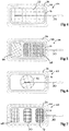
- a field controlling electrode 10 in accordance with the present invention which generally includes a conductive flexible member 14 having a top side 16 and a bottom side 18.
- an electrically driven master electrode 22 is disposed on the conductive flexible member for generating a current distribution in the conductive flexible member 14.
- An electrically undriven slave electrode 26 is disposed in a spaced apart relationship with the master electrode 22 for focusing or controlling the generated current distribution over an area of a user's body (not shown).
- the undriven slave electrode 26 is disposed on the bottom side 18 of the flexible member 14.
- the master electrode 22 is connected via a lead 30 to external electrical apparatus (not shown).
- a non-conductive flexible sheet 34 is disposed over the conductive flexible member 14 top side 16, master electrode 22, and lead 30 and adhered thereto by an adhesive layer 36.
- each of the master electrode 22 and slave electrode 26 is in the form of a grid, which comprises a conductive ink pattern.
- conductive ink patterns are disclosed in U.S. Patent No. 4.736,752 , which is incorporated herewith in its entirety for the purpose of teaching the use of conductive ink design.
- the conductive flexible member may be formed from carbon and PVC or any other suitable material.
- a suitable conductive hydrogel adhesive 40 is utilized for adhering the electrode 10 to a patient's skin (not shown).
- a plastic carrier 46 along with a silicone coating 44 for easy release may be provided in order to prevent inadvertent and/or premature adhesion to a patient (not shown) or other object to the hydrogel 40 with the carrier 46 being removed prior to application of the electrode 10 to the patient (not shown).
- FIG. 10 With reference to Figures 2 and 3 , top and bottom views of the electrode 10 are shown respectively, This embodiment illustrates not only that the master electrode 22 and slave electrode 26 have different planar shapes, but further multiple slave electrodes 26, in this case three, may be utilized in order to focus or control the generated current distribution in the conductive flexible member 14 by the master electrode 22.
- Electrode 54 is illustrated in Figures 4 and 5 with common reference characters representing identical or similar elements as shown in Figures 1-3 describing the electrode 10.
- slave electrodes 56, 58 are provided illustrating various arrays of grid patterns suitable for use for providing transcutaneous nerve and/or muscle stimulation to a user's body (not shown),
- FIG. 6 Another embodiment of a field controlling electrode 62, in accordance with the present invention, is illustrated in Figures 6 and 7 , with Figure 6 showing a top side and Figure 7 showing a bottom side with common reference characters hereinabove described in conjunction with the electrodes 10 and 54.
- the electrically driven master electrode 66 has a circular shape and three slave electrodes 68, 70, 72 are provided.
- the electrode 62 illustrates slave electrodes 68, 70, 72 having graded conductive ink patterns with varying line width and distance between lines of the pattern useful for focusing or controlling the generated current distribution in the flexible member 14 and the user's body (not shown) by the electrically driven master electrode 66.
- FIG. 8 and 9 there is shown yet another embodiment of a field controlling electrode 78 showing a master electrode 82 incorporating various grid designs and a planar shape and, as shown in Figure 9 , four slave electrodes 86, 88, 90, 92 with various planar shapes in grid configurations.
- This electrode 78 may be useful for stimulating the muscles proximal to a user's knee (not shown).
- an electrode 96 in accordance with the present invention may include an opaque non-conductive sheet 100 disposed over a conductive flexible member top side and master electrode, not seen in Figure 10 to enable visualization only of a slave electrode (not shown in Figure 10 ).
- construction of the electrode is concealed yet the electrode is identifiable by the number and shape of slave electrodes 26, 56,58,68,70, 72, 86, 88, 90, and 92,
- This visualization enables proper selection of the electrode by the user with the slave electrodes 26, 56, 58, 68, 70, 72, 86, 88, 90, and 92 facilitating proper placement of the electrode 10, 54, 62, 78 on an area (not shown) of a user's body (not shown).
- electrodes 104 and 108 illustrate the use of an electric shunt 112, 114, which may be in electrical communication with both or either of the lead 30, grid 22, and flexible member 14.
- the common reference numerals in Figures 11 and 12 represent identical or substantially similar elements as hereinabove discussed.
- FIG. 11 represents a transverse placement of a shunt 112 and Figure 12 illustrates a longitudinal placement of a shunt 114 with respect to the lead 30.
- the shunt may be of any suitable type such as a conductive pattern or discrete wires. The figures are merely representative of the shunt placement and the invention is not limited thereto.
- the shunt in combination with the dual-sided electrode provides greater current distribution than heretofore possible.
Landscapes
- Health & Medical Sciences (AREA)
- Engineering & Computer Science (AREA)
- Biomedical Technology (AREA)
- Nuclear Medicine, Radiotherapy & Molecular Imaging (AREA)
- Radiology & Medical Imaging (AREA)
- Life Sciences & Earth Sciences (AREA)
- Animal Behavior & Ethology (AREA)
- General Health & Medical Sciences (AREA)
- Public Health (AREA)
- Veterinary Medicine (AREA)
- Electrotherapy Devices (AREA)
Claims (10)
- Eine im Wesentlichen flache Feldsteuerelektrode (10) zum Bereitstellen von transkutaner Nerven- oder Muskelstimulation für den Körper eines Benutzers, wobei die Feldsteuerelektrode (10) aufweist:ein im Wesentlichen flaches leitendes flexibles Element (14) mit einer oberen Seite (16) und einer unteren Seite (18);eine im Wesentlichen flache elektrisch betriebene Master-Elektrode (22), die auf der oberen Seite (16) des leitenden flexiblen Elements (14) angeordnet ist, um eine Stromverteilung in dem leitenden flexiblen Element (14) zu erzeugen, wobei die Master-Elektrode (22) ein erstes leitendes Tintenmuster in Form eines ersten Gitters aufweist;eine im Wesentlichen flache nicht elektrisch betriebene Slave-Elektrode (26), die von der Master-Elektrode (22) beabstandet auf der unteren Seite (18) des leitenden flexiblen Elements (14) angeordnet ist, um die erzeugte Stromverteilung über einen Bereich des Körpers eines Benutzers zu fokussieren, wobei die Slave-Elektrode (26) ein zweites leitendes Tintenmuster in Form eines zweiten Gitters aufweist; undeine Zuleitung (30) in elektrischer Verbindung mit der Master-Elektrode (22), wobei die Zuleitung (30) zum Verbinden der Feldsteuerelektrode (10) mit externer elektrischer Ausrüstung vorgesehen ist.
- Feldsteuerelektrode (10) nach Anspruch 1 mit einem elektrischen Nebenschluss (112, 114) in direkter elektrischer Verbindung mit der Zuleitung (30) und Master-Elektrode (22) zum Steuern der in dem leitenden flexiblen Element (14) erzeugten Stromverteilung.
- Feldsteuerelektrode (10) nach Anspruch 2, wobei der Nebenschluss (112) transversal zu der Zuleitung (30) angeordnet ist.
- Feldsteuerelektrode (10) nach Anspruch 2, wobei der Nebenschluss (114) longitudinal zu der Zuleitung (30) angeordnet ist.
- Feldsteuerelektrode (10) nach Anspruch 1, weiterhin umfassend eine opake nichtleitende Folie (100), die über der oberen Seite (16) des leitenden flexiblen Elements (14) und Master-Elektrode angeordnet ist, wobei die opake nichtleitende Folie (100) eine Visualisierung nur der Slave-Elektrode (26) ermöglicht, wodurch eine korrekte Auswahl durch den Benutzer ermöglicht, was die korrekte Platzierung der Feldsteuerelektrode auf dem Bereich des Körpers des Benutzers erleichtert wird.
- Feldsteuerelektrode (10) nach Anspruch 1, wobei die Master-Elektrode (22) und die Slave-Elektrode (26) unterschiedliche planare Formen haben.
- Feldsteuerelektrode (10) nach Anspruch 1, wobei die Slave-Elektrode (26) eine Vielzahl von Slave-Elektroden (26) umfasst.
- Feldsteuerelektrode (10) nach Anspruch 7, wobei die Vielzahl von Slave-Elektroden (26) unterschiedliche Größen und/oder Formen haben.
- Feldsteuerelektrode (10) nach Anspruch 1, wobei die Slave-Elektrode (26) ein abgestuftes leitendes Tintenmuster mit variierender Linienbreite und/oder Abstand zwischen den Linien des Musters aufweist.
- Feldsteuerelektrode (10) nach Anspruch 1, wobei die Master-Elektrode (22) ein gradiertes leitendes Tintenmuster mit variierender Linienbreite und/oder Abstand zwischen den Linien des Musters aufweist.
Applications Claiming Priority (2)
| Application Number | Priority Date | Filing Date | Title |
|---|---|---|---|
| US13/371,739 US9089684B2 (en) | 2012-02-13 | 2012-02-13 | Dual-sided current controlling electrode |
| PCT/US2013/024890 WO2013122794A1 (en) | 2012-02-13 | 2013-02-06 | Dual-sided current controlling electrode |
Publications (3)
| Publication Number | Publication Date |
|---|---|
| EP2814562A1 EP2814562A1 (de) | 2014-12-24 |
| EP2814562A4 EP2814562A4 (de) | 2015-10-28 |
| EP2814562B1 true EP2814562B1 (de) | 2019-04-10 |
Family
ID=48946257
Family Applications (1)
| Application Number | Title | Priority Date | Filing Date |
|---|---|---|---|
| EP13748855.7A Active EP2814562B1 (de) | 2012-02-13 | 2013-02-06 | Doppelseitige elektrode mit gesteuertem stromfluss |
Country Status (3)
| Country | Link |
|---|---|
| US (1) | US9089684B2 (de) |
| EP (1) | EP2814562B1 (de) |
| WO (1) | WO2013122794A1 (de) |
Families Citing this family (5)
| Publication number | Priority date | Publication date | Assignee | Title |
|---|---|---|---|---|
| AU354140S (en) * | 2013-10-02 | 2014-03-04 | Pierenkemper Gmbh | Electrostimulation apparatus |
| CN113286628A (zh) * | 2018-11-01 | 2021-08-20 | 诚为本创新有限责任公司 | 通过电场治疗具有转移性疾病的患者中的多个肿瘤的设备和方法 |
| EP3911407A1 (de) | 2019-01-16 | 2021-11-24 | Palmm Co. | Vorrichtungen, systeme und verfahren zur abgabe von elektrischem strom an den körper |
| USD1064290S1 (en) | 2023-08-01 | 2025-02-25 | Djo, Llc | Electrode with conductive pattern |
| USD1064289S1 (en) | 2023-08-01 | 2025-02-25 | Djo, Llc | Electrode with conductive pattern |
Family Cites Families (11)
| Publication number | Priority date | Publication date | Assignee | Title |
|---|---|---|---|---|
| US4867166A (en) | 1985-06-14 | 1989-09-19 | Jens Axelgaard | Electrical stimulation electrode |
| US4736752A (en) | 1986-11-28 | 1988-04-12 | Axelgaard Manufacturing Co., Ltd. | Transcutaneous medical electrode |
| US5447526A (en) | 1992-12-24 | 1995-09-05 | Karsdon; Jeffrey | Transcutaneous electric muscle/nerve controller/feedback unit |
| US5904712A (en) | 1997-06-12 | 1999-05-18 | Axelgaard Manufacturing Co., Ltd. | Current-controlling electrode |
| US6745082B2 (en) | 2001-10-22 | 2004-06-01 | Jens Axelgaard | Current-controlling electrode with adjustable contact area |
| US7627384B2 (en) | 2004-11-15 | 2009-12-01 | Bio Control Medical (B.C.M.) Ltd. | Techniques for nerve stimulation |
| US20090209840A1 (en) * | 2003-02-06 | 2009-08-20 | Jens Axelgaard | Electrode chain |
| US7742828B2 (en) * | 2006-09-29 | 2010-06-22 | Tyco Healthcare Group Lp | Medical electrode suitable for high-energy stimulation |
| WO2010027874A2 (en) | 2008-08-26 | 2010-03-11 | Niveus Medical, Inc. | Device, system, and method to improve powered muscle stimulation performance in the presence of tissue edema |
| US8320988B2 (en) | 2009-04-09 | 2012-11-27 | Axelgaard Manufacturing Co., Ltd. | Multi-electrode strung on a common connector |
| US8473072B2 (en) | 2010-06-08 | 2013-06-25 | Axelgaard Manufacturing Company, Ltd. | Customizable medical electrode |
-
2012
- 2012-02-13 US US13/371,739 patent/US9089684B2/en active Active
-
2013
- 2013-02-06 EP EP13748855.7A patent/EP2814562B1/de active Active
- 2013-02-06 WO PCT/US2013/024890 patent/WO2013122794A1/en not_active Ceased
Also Published As
| Publication number | Publication date |
|---|---|
| EP2814562A1 (de) | 2014-12-24 |
| EP2814562A4 (de) | 2015-10-28 |
| US9089684B2 (en) | 2015-07-28 |
| US20130211488A1 (en) | 2013-08-15 |
| WO2013122794A1 (en) | 2013-08-22 |
Similar Documents
| Publication | Publication Date | Title |
|---|---|---|
| US8874231B2 (en) | Customizable medical electrode | |
| US5904712A (en) | Current-controlling electrode | |
| US6745082B2 (en) | Current-controlling electrode with adjustable contact area | |
| EP2340080B1 (de) | Elektrodenkette | |
| EP2160131B1 (de) | Medizinische elektrode mit ausschnitten zur regelung der lateralen leitfähigkeit | |
| US8320988B2 (en) | Multi-electrode strung on a common connector | |
| EP2066395B1 (de) | Feuchtigkeitsbeständige elektrode mit kantenschutz | |
| EP3024533B1 (de) | Elektrodenpad | |
| US20040158305A1 (en) | Reverse current controlling electrode | |
| WO2011159923A3 (en) | Implantable micro-component electrodes | |
| CA2732732A1 (en) | Portable assemblies, systems, and methods for providing functional or therapeutic neurostimulation | |
| CN101244311B (zh) | 医用电极 | |
| US9089684B2 (en) | Dual-sided current controlling electrode | |
| US5843155A (en) | Current-controlling electrode system | |
| KR20130100443A (ko) | 생체 자극용 전극 | |
| US20250128054A1 (en) | An electrode pad for electro-stimulation and method of manufacturing same | |
| US8457735B2 (en) | Field controlling electrode |
Legal Events
| Date | Code | Title | Description |
|---|---|---|---|
| PUAI | Public reference made under article 153(3) epc to a published international application that has entered the european phase |
Free format text: ORIGINAL CODE: 0009012 |
|
| 17P | Request for examination filed |
Effective date: 20140915 |
|
| AK | Designated contracting states |
Kind code of ref document: A1 Designated state(s): AL AT BE BG CH CY CZ DE DK EE ES FI FR GB GR HR HU IE IS IT LI LT LU LV MC MK MT NL NO PL PT RO RS SE SI SK SM TR |
|
| AX | Request for extension of the european patent |
Extension state: BA ME |
|
| DAX | Request for extension of the european patent (deleted) | ||
| RA4 | Supplementary search report drawn up and despatched (corrected) |
Effective date: 20150924 |
|
| RIC1 | Information provided on ipc code assigned before grant |
Ipc: A61N 1/18 20060101ALN20150918BHEP Ipc: A61N 1/04 20060101AFI20150918BHEP |
|
| RIC1 | Information provided on ipc code assigned before grant |
Ipc: A61N 1/18 20060101ALN20180621BHEP Ipc: A61N 1/04 20060101AFI20180621BHEP |
|
| GRAP | Despatch of communication of intention to grant a patent |
Free format text: ORIGINAL CODE: EPIDOSNIGR1 |
|
| STAA | Information on the status of an ep patent application or granted ep patent |
Free format text: STATUS: GRANT OF PATENT IS INTENDED |
|
| INTG | Intention to grant announced |
Effective date: 20180823 |
|
| GRAS | Grant fee paid |
Free format text: ORIGINAL CODE: EPIDOSNIGR3 |
|
| GRAA | (expected) grant |
Free format text: ORIGINAL CODE: 0009210 |
|
| STAA | Information on the status of an ep patent application or granted ep patent |
Free format text: STATUS: THE PATENT HAS BEEN GRANTED |
|
| AK | Designated contracting states |
Kind code of ref document: B1 Designated state(s): AL AT BE BG CH CY CZ DE DK EE ES FI FR GB GR HR HU IE IS IT LI LT LU LV MC MK MT NL NO PL PT RO RS SE SI SK SM TR |
|
| REG | Reference to a national code |
Ref country code: GB Ref legal event code: FG4D |
|
| REG | Reference to a national code |
Ref country code: CH Ref legal event code: EP Ref country code: AT Ref legal event code: REF Ref document number: 1117868 Country of ref document: AT Kind code of ref document: T Effective date: 20190415 |
|
| REG | Reference to a national code |
Ref country code: IE Ref legal event code: FG4D |
|
| REG | Reference to a national code |
Ref country code: DE Ref legal event code: R096 Ref document number: 602013053696 Country of ref document: DE |
|
| REG | Reference to a national code |
Ref country code: NL Ref legal event code: MP Effective date: 20190410 |
|
| REG | Reference to a national code |
Ref country code: LT Ref legal event code: MG4D |
|
| REG | Reference to a national code |
Ref country code: AT Ref legal event code: MK05 Ref document number: 1117868 Country of ref document: AT Kind code of ref document: T Effective date: 20190410 |
|
| PG25 | Lapsed in a contracting state [announced via postgrant information from national office to epo] |
Ref country code: NL Free format text: LAPSE BECAUSE OF FAILURE TO SUBMIT A TRANSLATION OF THE DESCRIPTION OR TO PAY THE FEE WITHIN THE PRESCRIBED TIME-LIMIT Effective date: 20190410 |
|
| PG25 | Lapsed in a contracting state [announced via postgrant information from national office to epo] |
Ref country code: NO Free format text: LAPSE BECAUSE OF FAILURE TO SUBMIT A TRANSLATION OF THE DESCRIPTION OR TO PAY THE FEE WITHIN THE PRESCRIBED TIME-LIMIT Effective date: 20190710 Ref country code: FI Free format text: LAPSE BECAUSE OF FAILURE TO SUBMIT A TRANSLATION OF THE DESCRIPTION OR TO PAY THE FEE WITHIN THE PRESCRIBED TIME-LIMIT Effective date: 20190410 Ref country code: HR Free format text: LAPSE BECAUSE OF FAILURE TO SUBMIT A TRANSLATION OF THE DESCRIPTION OR TO PAY THE FEE WITHIN THE PRESCRIBED TIME-LIMIT Effective date: 20190410 Ref country code: PT Free format text: LAPSE BECAUSE OF FAILURE TO SUBMIT A TRANSLATION OF THE DESCRIPTION OR TO PAY THE FEE WITHIN THE PRESCRIBED TIME-LIMIT Effective date: 20190910 Ref country code: SE Free format text: LAPSE BECAUSE OF FAILURE TO SUBMIT A TRANSLATION OF THE DESCRIPTION OR TO PAY THE FEE WITHIN THE PRESCRIBED TIME-LIMIT Effective date: 20190410 Ref country code: AL Free format text: LAPSE BECAUSE OF FAILURE TO SUBMIT A TRANSLATION OF THE DESCRIPTION OR TO PAY THE FEE WITHIN THE PRESCRIBED TIME-LIMIT Effective date: 20190410 Ref country code: ES Free format text: LAPSE BECAUSE OF FAILURE TO SUBMIT A TRANSLATION OF THE DESCRIPTION OR TO PAY THE FEE WITHIN THE PRESCRIBED TIME-LIMIT Effective date: 20190410 Ref country code: LT Free format text: LAPSE BECAUSE OF FAILURE TO SUBMIT A TRANSLATION OF THE DESCRIPTION OR TO PAY THE FEE WITHIN THE PRESCRIBED TIME-LIMIT Effective date: 20190410 |
|
| PG25 | Lapsed in a contracting state [announced via postgrant information from national office to epo] |
Ref country code: BG Free format text: LAPSE BECAUSE OF FAILURE TO SUBMIT A TRANSLATION OF THE DESCRIPTION OR TO PAY THE FEE WITHIN THE PRESCRIBED TIME-LIMIT Effective date: 20190710 Ref country code: RS Free format text: LAPSE BECAUSE OF FAILURE TO SUBMIT A TRANSLATION OF THE DESCRIPTION OR TO PAY THE FEE WITHIN THE PRESCRIBED TIME-LIMIT Effective date: 20190410 Ref country code: PL Free format text: LAPSE BECAUSE OF FAILURE TO SUBMIT A TRANSLATION OF THE DESCRIPTION OR TO PAY THE FEE WITHIN THE PRESCRIBED TIME-LIMIT Effective date: 20190410 Ref country code: LV Free format text: LAPSE BECAUSE OF FAILURE TO SUBMIT A TRANSLATION OF THE DESCRIPTION OR TO PAY THE FEE WITHIN THE PRESCRIBED TIME-LIMIT Effective date: 20190410 Ref country code: GR Free format text: LAPSE BECAUSE OF FAILURE TO SUBMIT A TRANSLATION OF THE DESCRIPTION OR TO PAY THE FEE WITHIN THE PRESCRIBED TIME-LIMIT Effective date: 20190711 |
|
| PG25 | Lapsed in a contracting state [announced via postgrant information from national office to epo] |
Ref country code: AT Free format text: LAPSE BECAUSE OF FAILURE TO SUBMIT A TRANSLATION OF THE DESCRIPTION OR TO PAY THE FEE WITHIN THE PRESCRIBED TIME-LIMIT Effective date: 20190410 Ref country code: IS Free format text: LAPSE BECAUSE OF FAILURE TO SUBMIT A TRANSLATION OF THE DESCRIPTION OR TO PAY THE FEE WITHIN THE PRESCRIBED TIME-LIMIT Effective date: 20190810 |
|
| REG | Reference to a national code |
Ref country code: DE Ref legal event code: R097 Ref document number: 602013053696 Country of ref document: DE |
|
| PG25 | Lapsed in a contracting state [announced via postgrant information from national office to epo] |
Ref country code: CZ Free format text: LAPSE BECAUSE OF FAILURE TO SUBMIT A TRANSLATION OF THE DESCRIPTION OR TO PAY THE FEE WITHIN THE PRESCRIBED TIME-LIMIT Effective date: 20190410 Ref country code: RO Free format text: LAPSE BECAUSE OF FAILURE TO SUBMIT A TRANSLATION OF THE DESCRIPTION OR TO PAY THE FEE WITHIN THE PRESCRIBED TIME-LIMIT Effective date: 20190410 Ref country code: SK Free format text: LAPSE BECAUSE OF FAILURE TO SUBMIT A TRANSLATION OF THE DESCRIPTION OR TO PAY THE FEE WITHIN THE PRESCRIBED TIME-LIMIT Effective date: 20190410 Ref country code: EE Free format text: LAPSE BECAUSE OF FAILURE TO SUBMIT A TRANSLATION OF THE DESCRIPTION OR TO PAY THE FEE WITHIN THE PRESCRIBED TIME-LIMIT Effective date: 20190410 Ref country code: DK Free format text: LAPSE BECAUSE OF FAILURE TO SUBMIT A TRANSLATION OF THE DESCRIPTION OR TO PAY THE FEE WITHIN THE PRESCRIBED TIME-LIMIT Effective date: 20190410 |
|
| PLBE | No opposition filed within time limit |
Free format text: ORIGINAL CODE: 0009261 |
|
| STAA | Information on the status of an ep patent application or granted ep patent |
Free format text: STATUS: NO OPPOSITION FILED WITHIN TIME LIMIT |
|
| PG25 | Lapsed in a contracting state [announced via postgrant information from national office to epo] |
Ref country code: IT Free format text: LAPSE BECAUSE OF FAILURE TO SUBMIT A TRANSLATION OF THE DESCRIPTION OR TO PAY THE FEE WITHIN THE PRESCRIBED TIME-LIMIT Effective date: 20190410 Ref country code: SM Free format text: LAPSE BECAUSE OF FAILURE TO SUBMIT A TRANSLATION OF THE DESCRIPTION OR TO PAY THE FEE WITHIN THE PRESCRIBED TIME-LIMIT Effective date: 20190410 |
|
| 26N | No opposition filed |
Effective date: 20200113 |
|
| PG25 | Lapsed in a contracting state [announced via postgrant information from national office to epo] |
Ref country code: TR Free format text: LAPSE BECAUSE OF FAILURE TO SUBMIT A TRANSLATION OF THE DESCRIPTION OR TO PAY THE FEE WITHIN THE PRESCRIBED TIME-LIMIT Effective date: 20190410 |
|
| PG25 | Lapsed in a contracting state [announced via postgrant information from national office to epo] |
Ref country code: SI Free format text: LAPSE BECAUSE OF FAILURE TO SUBMIT A TRANSLATION OF THE DESCRIPTION OR TO PAY THE FEE WITHIN THE PRESCRIBED TIME-LIMIT Effective date: 20190410 |
|
| REG | Reference to a national code |
Ref country code: CH Ref legal event code: PL |
|
| REG | Reference to a national code |
Ref country code: BE Ref legal event code: MM Effective date: 20200229 |
|
| PG25 | Lapsed in a contracting state [announced via postgrant information from national office to epo] |
Ref country code: LU Free format text: LAPSE BECAUSE OF NON-PAYMENT OF DUE FEES Effective date: 20200206 Ref country code: MC Free format text: LAPSE BECAUSE OF FAILURE TO SUBMIT A TRANSLATION OF THE DESCRIPTION OR TO PAY THE FEE WITHIN THE PRESCRIBED TIME-LIMIT Effective date: 20190410 |
|
| PG25 | Lapsed in a contracting state [announced via postgrant information from national office to epo] |
Ref country code: LI Free format text: LAPSE BECAUSE OF NON-PAYMENT OF DUE FEES Effective date: 20200229 Ref country code: CH Free format text: LAPSE BECAUSE OF NON-PAYMENT OF DUE FEES Effective date: 20200229 |
|
| PG25 | Lapsed in a contracting state [announced via postgrant information from national office to epo] |
Ref country code: IE Free format text: LAPSE BECAUSE OF NON-PAYMENT OF DUE FEES Effective date: 20200206 |
|
| PG25 | Lapsed in a contracting state [announced via postgrant information from national office to epo] |
Ref country code: BE Free format text: LAPSE BECAUSE OF NON-PAYMENT OF DUE FEES Effective date: 20200229 |
|
| PG25 | Lapsed in a contracting state [announced via postgrant information from national office to epo] |
Ref country code: MT Free format text: LAPSE BECAUSE OF FAILURE TO SUBMIT A TRANSLATION OF THE DESCRIPTION OR TO PAY THE FEE WITHIN THE PRESCRIBED TIME-LIMIT Effective date: 20190410 Ref country code: CY Free format text: LAPSE BECAUSE OF FAILURE TO SUBMIT A TRANSLATION OF THE DESCRIPTION OR TO PAY THE FEE WITHIN THE PRESCRIBED TIME-LIMIT Effective date: 20190410 |
|
| PG25 | Lapsed in a contracting state [announced via postgrant information from national office to epo] |
Ref country code: MK Free format text: LAPSE BECAUSE OF FAILURE TO SUBMIT A TRANSLATION OF THE DESCRIPTION OR TO PAY THE FEE WITHIN THE PRESCRIBED TIME-LIMIT Effective date: 20190410 |
|
| PGFP | Annual fee paid to national office [announced via postgrant information from national office to epo] |
Ref country code: GB Payment date: 20260227 Year of fee payment: 14 |
|
| PGFP | Annual fee paid to national office [announced via postgrant information from national office to epo] |
Ref country code: DE Payment date: 20260227 Year of fee payment: 14 |
|
| PGFP | Annual fee paid to national office [announced via postgrant information from national office to epo] |
Ref country code: FR Payment date: 20260225 Year of fee payment: 14 |