EP2814650B1 - Dispositif destiné à être utilisé dans un moule pour le thermoformage du type fournissant une surface courbée à double courbure pouvant être reconfigurée dynamiquement présentant une structure ouverte - Google Patents
Dispositif destiné à être utilisé dans un moule pour le thermoformage du type fournissant une surface courbée à double courbure pouvant être reconfigurée dynamiquement présentant une structure ouverte Download PDFInfo
- Publication number
- EP2814650B1 EP2814650B1 EP13735766.1A EP13735766A EP2814650B1 EP 2814650 B1 EP2814650 B1 EP 2814650B1 EP 13735766 A EP13735766 A EP 13735766A EP 2814650 B1 EP2814650 B1 EP 2814650B1
- Authority
- EP
- European Patent Office
- Prior art keywords
- shaped elements
- ribbon
- rod
- elastically deformable
- deformable material
- Prior art date
- Legal status (The legal status is an assumption and is not a legal conclusion. Google has not performed a legal analysis and makes no representation as to the accuracy of the status listed.)
- Active
Links
Images


Classifications
-
- B—PERFORMING OPERATIONS; TRANSPORTING
- B29—WORKING OF PLASTICS; WORKING OF SUBSTANCES IN A PLASTIC STATE IN GENERAL
- B29C—SHAPING OR JOINING OF PLASTICS; SHAPING OF MATERIAL IN A PLASTIC STATE, NOT OTHERWISE PROVIDED FOR; AFTER-TREATMENT OF THE SHAPED PRODUCTS, e.g. REPAIRING
- B29C51/00—Shaping by thermoforming, i.e. shaping sheets or sheet like preforms after heating, e.g. shaping sheets in matched moulds or by deep-drawing; Apparatus therefor
- B29C51/26—Component parts, details or accessories; Auxiliary operations
- B29C51/30—Moulds
-
- B—PERFORMING OPERATIONS; TRANSPORTING
- B29—WORKING OF PLASTICS; WORKING OF SUBSTANCES IN A PLASTIC STATE IN GENERAL
- B29C—SHAPING OR JOINING OF PLASTICS; SHAPING OF MATERIAL IN A PLASTIC STATE, NOT OTHERWISE PROVIDED FOR; AFTER-TREATMENT OF THE SHAPED PRODUCTS, e.g. REPAIRING
- B29C33/00—Moulds or cores; Details thereof or accessories therefor
- B29C33/30—Mounting, exchanging or centering
- B29C33/308—Adjustable moulds
Definitions
- the present invention relates to a device for use in a mould for thermoforming, the moulds of the type providing a curved, double-curved, dynamically reconfigurable surface with an open structure as defined in the preamble of claim 1.
- a device of such kind is known from US 2005/064148A1 .
- Digitally-controlled moulds that have the ability to produce a physical representation of a digitally designed surface quickly and precisely, based on data from a CAD program are advantageous when producing series of unique curved and double-curved blanks.
- a branch of such dynamically reconfigurable thermoforming moulds includes moulds that are intended to create even points on single- and double-curved surfaces for use in e.g. production of individually manufactured facade elements in organically-shaped architecture.
- a number of attempts have been made to produce such a mould, and all of them shared a common factor of a large or small number of actuators, each of which defines a point on a surface.
- One end of the actuators is fixed to a frame, and membranes or plates are attached to their free ends, if necessary supported by a network of flexible profiles that are intended to form a surface that can be used for casting, etc.
- FR 2612545 A and US 5,851,563 describe a mould apparatus in which a number of actuators are arranged in a rectangular pattern, controlled individually in the longitudinal direction by a computer/processor. On a ball joint on the free end of each actuator a rectangular plate is fitted, partly overlapping adjacent plates in such a way that the plates together form a sealed surface. The surface so formed is thus divided up into large or small surfaces, depending on the number of actuators and their common spacing.
- One problem with the prior art apparatus is that only when there is a large number of closely-spaced actuators will the surface produced appear uniform, but will still consist of a number of flat facets, as the rectangular plates will not provide even transitions and continual curves. In addition to that, closely-spaced actuators is a significantly more expensive solution.
- GB 2268699 A describes an apparatus for forming glass fibre-reinforced plastic laminates, in which an elastically deformable material is supported by a number of distributed actuators.
- the addition of fibres in the laminate achieves rigidity, and the actuators are used to force the basically flat laminate to assume a single- or double-curved shape. This takes place in several stages, in which the addition of the fibre adds rigidity to the laminate prior to a deformation a number of times, after which further fibre is added and the laminate is cured so that it maintains the new shape.
- the patent indicates, to achieve an even surface, in relation to the aforementioned mould apparatus, with continued curves with a spacing between the actuators of 50 cm to 100 cm, as the rigidity of the laminate results in an interpolation between the points defined by the actuators.
- One advantage with the prior art apparatus is that an even, continual surface is achieved using relatively few actuators.
- One problem with the apparatus is that the surface precision depends on the ability during the process to control the rigidity of the laminate, which means that the apparatus can only be used for production of laminates.
- the fine level of control of rigidity requires a relatively high, and cost-increasing, complexity of machinery, processes and calculations.
- US 4,522,641 indicates a process for production of three-dimensional glass elements in which a rectangular grid of interwoven elastically deformable supports are connected in nodal points to an underlying adjustable system of e.g. actuators.
- an underlying adjustable system of e.g. actuators.
- the rigidity of the interwoven supports forms the curves in the direction of the grid, between the nodal points defined by the underlying adjustable system.
- a sheet or plate of elastically deformable material is placed in multiple layers over the grid, where it provides a sealed and heat-insulated surface that can be used to cast glass elements.
- the object of this invention is to provide a device of the type described in the introduction that will provide an easy and fast process for creating a single- or double-curved surface using few actuators in relation to the possible curves.
- a further object of the invention is that the established closely-spaced points on the surface are evenly and uniformly distributed with continual curves in all directions.
- the double-curved dynamically reconfigurable surface instead of consisting of well-defined points, is actually formed by interpolation between a number of parallel continuous line-shaped rods that make up an infinite number of points, which produces a more even surface than that which is obtainable using the prior art segmented and/or interwoven supports.
- the device incorporating the flexible system of internally relatively angled layers of spaced point-supported parallel continuous rod- and/ribbon-shaped elements of elastically deformable material must be arranged in such a way that they form support points with variable spacing between adjacent support points, the spacing ranging from 0 to 100 cm.
- This extremely open, grid-shaped structure that occurs between the internally relatively angled layers of rod- and/or ribbon-shaped elements of elastically deformable material, permits good ventilation below and within the dynamically reconfigurable surface, and at the same time as its surface is evenly curved with good support for the surface, or a flexible coating applied to it.
- the deflection of the internally displaceable rod- and/or ribbon-shaped elements of elastically deformable material from an initial shape can be performed by the application of a force resulting from the movable free ends of a number of linear actuators, e.g. of the electromechanical type, to which the rod- and/or ribbon-shaped elements of elastically deformable material are mechanically connected in such a way that the position of a given point on the surface is determined from the position of the free end of an associated given actuator.
- a number of linear actuators e.g. of the electromechanical type
- the device according to the invention can be provided with registration units that register data regarding the positions of the free ends of the respective linear actuators that are mechanically connected to the rod- or ribbon-shaped elements of elastically deformable material, the data being registered and sent to a computer processing unit with signal sensors for controlling the movement of the individual actuators' free ends, and thus the point in the flexible system that belongs to the free end of the actuator, to a pre-defined position.
- each individual actuator can independently be brought to assume a pre-defined position which means that the points on the surface that are formed by the flexible system can be made to create a course through a series of defined points, that could, for example, be read off from a digital presentation of a surface.
- the rod- and/or ribbon-shaped elements of elastically deformable material may be internally connected with springs, the number and location of which depend on the potential deflection of the deflected reconfigurable double-curved surface.
- At least one of the springs' spring constants may be adjustable.
- the spring constants for the springs may be individually adjustable by means of actuators connected to a control unit that is connected to a computer processing unit for controlling the respective springs' spring constants.
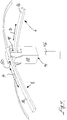
- Fig. 1 is a perspective view of device 2 for use in a mould for thermoforming, for moulds of the type that provide a curved double-curved, dynamically reconfigurable surface, with an open structure.
- the curved, double-curved dynamically reconfigurable surface 4 with an open structure is defined by a flexible system consisting of a number of angled layers 6, 8, 10, 12, 14 of spaced point-supported parallel rod- and/or ribbon-shaped elements 16, 18, 20, 22, 24 of elastically deformable material, in which the upward-facing, highest surfaces 26 of the rod- or ribbon-shaped elements 14, 16, 18, 20, 24, in the embodiment shown, the highest located surfaces 26 of the rod-shaped elements 24, define the double-curved reconfigurable surface 4 by relative displacements between the fixing points 28, 30, 32, 34 for the point-supported rod- or ribbon-shaped elements 14,16, 18, 20, 24.
- Layers 10, 12, that are made up of the rod-shaped elements 20, 22 consisting of elastically deformable material, are supported in the fixing points 30, 32, that are made up of brackets that are displaceably journaled in layers 8, 6 of the ribbon-shaped elements 18, 16, which are indicated by arrows C and D in Fig. 3 .
- all of the springs' spring constants may be individually adjustable by means of actuators that are not illustrated, connected to a control unit that is not illustrated, which is connected to a data processing unit not illustrated for controlling the springs' spring constants.
Landscapes
- Engineering & Computer Science (AREA)
- Mechanical Engineering (AREA)
- Moulds For Moulding Plastics Or The Like (AREA)
Claims (9)
- Dispositif (2) destiné à être utilisé dans le thermoformage de moules, pour des moules du type qui permet de fournir une surface incurvée à double courbure (4), pouvant être reconfigurée dynamiquement, présentant une structure ouverte, dans lequel la surface incurvée à double courbure (4), pouvant être reconfigurée dynamiquement, présentant une structure ouverte, est définie par interpolation entre des éléments en forme de tiges et/ou de rubans espacés (16, 18, 20, 22, 24) consistant en un système flexible comprenant un certain nombre de couches inclinées (6, 8, 10, 12, 14) d'éléments en forme de tiges et/ou de rubans parallèles espacés (16, 18, 20, 22, 24) supportés en plusieurs points constitués d'un matériau déformable élastiquement, dans lequel des points d'ancrage décalés les uns par rapport aux autres (28, 30, 32, 34) pour les éléments en forme de tiges et/ou de rubans (16, 18, 20, 22, 24) supportés en plusieurs points par le biais des surfaces les plus élevées dirigées vers le haut (26) des éléments en forme de tiges ou de rubans (24) définissent la surface à double courbure (4) pouvant être reconfigurée,
caractérisé en ce que
les couches inclinées relativement vers l'intérieur (6, 8, 10, 12, 14) des éléments en forme de tiges et/ou de rubans (16, 18, 20, 22, 24) varient en épaisseur et/ou en rigidité. - Dispositif (2) selon la revendication 1, ledit dispositif comprenant le système flexible constitué de couches inclinées vers l'intérieur (6, 8, 10, 12, 14) d'éléments en forme de tiges et/ou de rubans parallèles espacés supportés en plusieurs points (16, 18, 20, 22, 24) constitués d'un matériau déformable élastiquement, qui sont disposés de sorte qu'ils forment des points de support (34) avec un espacement variable entre des points de support adjacents (26), l'espacement étant compris entre 0 et 100 cm.
- Dispositif (2) selon l'une quelconque des revendications 1 ou 2, dans lequel la surface incurvée à double courbure (4), pouvant être reconfigurée dynamiquement, présentant une structure ouverte, est fournie par un système flexible sous-jacent (46, 28, 6, 8, 10, 12, 14) consistant en des éléments, pouvant être déplacés à l'intérieur, en forme de tiges et/ou de rubans (16, 18, 20, 22, 24) constitués d'un matériau déformable élastiquement, disposés en deux ou plus de deux couches inclinées relativement vers l'intérieur (6, 8, 10, 12, 14) qui, dans l'état d'utilisation du dispositif, sont déviés et peuvent provoquer des déplacements relatifs entre les éléments en forme de tiges ou de rubans (16, 18, 20, 22, 24).
- Dispositif (2) selon l'une quelconque des revendications 1 à 3, dans lequel la déviation des éléments, pouvant être déplacés à l'intérieur, en forme de tiges et/ou de rubans (16, 18, 20, 22, 24) constitués d'un matériau déformable élastiquement, à partir d'une forme de départ, est créée par une force partant des extrémités libres mobiles (44) d'un certain nombre d'actionneurs (46), par exemple du type électro-mécanique, auxquels les éléments en forme de tiges et/ou de rubans (16, 18, 20, 22, 24) constitués d'un matériau déformable élastiquement sont reliés mécaniquement de telle sorte que la position d'un point donné sur une surface est déterminée sur la base de la position de l'extrémité libre (44) d'un actionneur associé donné (46).
- Dispositif (2) selon l'une quelconque des revendications 1 à 4, ledit dispositif comprenant des unités d'enregistrement pour l'enregistrement des données concernant les positions des extrémités libres (44) des actionneurs respectifs (46) qui sont reliés mécaniquement à des points de support (28, 30, 32, 34) pour les éléments en forme de tiges et/ou de rubans (16, 18, 20, 22, 24) constitués d'un matériau déformable élastiquement, les données enregistrées étant transmises à une unité de traitement de données avec des capteurs permettant de commander le mouvement des extrémités libres (44) des actionneurs individuels, et donc du point dans le système flexible qui appartient à l'extrémité libre de l'actionneur, jusqu'à une position préférée.
- Dispositif (2) selon l'une quelconque des revendications 1 à 5, dans lequel les éléments en forme de tiges et/ou de rubans (16, 18) constitués d'un matériau déformable élastiquement, disposés en couches inclinées relativement vers l'intérieur, au niveau de premiers mécanismes de fixation (28), sont journalisés de manière déplaçable et/ou inclinable par rapport aux extrémités libres déplaçables (44) des actionneurs (46), et, sur les éléments en forme de rubans (16, 18) entre les actionneurs (46), des deuxièmes mécanismes de fixation (30) journalisés de manière déplaçable et des troisièmes mécanismes de fixation (32) journalisés de manière déplaçable sont présents pour les éléments en forme de tiges parallèles espacés (20, 22) constitués d'un matériau déformable élastiquement, dans lequel les mécanismes de fixation (30, 32) des éléments en forme de tiges et/ou de rubans parallèles espacés (20, 22) constitués d'un matériau déformable élastiquement sont journalisés de manière déplaçable, et lesdits mécanismes de fixation (30, 32) sur le côté en regard des éléments en forme de rubans (16, 18) constitués d'un matériau déformable élastiquement comprennent un quatrième mécanisme de fixation (34) pour les éléments en forme de tiges parallèles espacés (24) qui sont inclinés par rapport aux éléments en forme de rubans (18).
- Dispositif (2) selon l'une quelconque des revendications 1-6, dans lequel les éléments en forme de tiges et/ou de rubans (20, 22) constitués d'un matériau déformable élastiquement sont reliés mutuellement à des ressorts (54), dont le nombre et l'emplacement dépendent de la déviation possible de la surface à double courbure (4) déviée pouvant être reconfigurée.
- Dispositif (2) selon la revendication 7, dans lequel la constante de rappel d'au moins un des ressorts est ajustable.
- Dispositif (2) selon la revendication 8, dans lequel les constantes de rappel des ressorts (54) sont ajustables individuellement par les actionneurs qui sont reliés à une unité de commande reliée à une unité de traitement de données permettant de régler les constantes de rappel des ressorts respectifs.
Applications Claiming Priority (2)
| Application Number | Priority Date | Filing Date | Title |
|---|---|---|---|
| DKPA201200035 | 2012-01-13 | ||
| PCT/DK2013/050010 WO2013104369A1 (fr) | 2012-01-13 | 2013-01-11 | Dispositif destiné à être utilisé dans un moule pour le thermoformage du type fournissant une surface courbée à double courbure pouvant être reconfigurée dynamiquement présentant une structure ouverte |
Publications (3)
| Publication Number | Publication Date |
|---|---|
| EP2814650A1 EP2814650A1 (fr) | 2014-12-24 |
| EP2814650A4 EP2814650A4 (fr) | 2015-12-23 |
| EP2814650B1 true EP2814650B1 (fr) | 2017-12-13 |
Family
ID=48781059
Family Applications (1)
| Application Number | Title | Priority Date | Filing Date |
|---|---|---|---|
| EP13735766.1A Active EP2814650B1 (fr) | 2012-01-13 | 2013-01-11 | Dispositif destiné à être utilisé dans un moule pour le thermoformage du type fournissant une surface courbée à double courbure pouvant être reconfigurée dynamiquement présentant une structure ouverte |
Country Status (4)
| Country | Link |
|---|---|
| EP (1) | EP2814650B1 (fr) |
| DK (1) | DK2814650T3 (fr) |
| ES (1) | ES2660403T3 (fr) |
| WO (1) | WO2013104369A1 (fr) |
Families Citing this family (4)
| Publication number | Priority date | Publication date | Assignee | Title |
|---|---|---|---|---|
| IT201700033240A1 (it) * | 2017-03-27 | 2018-09-27 | Stamtech S R L | Apparecchiatura perfezionata per la modellazione di prodotti |
| EP3746277A4 (fr) * | 2018-01-31 | 2021-10-20 | The University of Melbourne | Modèle de mise en forme variable |
| CN115195091A (zh) * | 2022-05-27 | 2022-10-18 | 肖丽丽 | 一种可变型模具平台装置及曲面件的制备方法 |
| CN114770439B (zh) * | 2022-06-02 | 2023-03-21 | 吉林大学 | 一种用于曲面件的柔性多点支撑装置 |
Family Cites Families (4)
| Publication number | Priority date | Publication date | Assignee | Title |
|---|---|---|---|---|
| US4527783A (en) * | 1983-04-26 | 1985-07-09 | Grumman Aerospace Corporation | Universal contoured parts holding fixture |
| US4897102A (en) * | 1989-03-14 | 1990-01-30 | Libbey-Owens-Ford Co. | Glass sheet press bending mold |
| GB2268699B (en) * | 1992-07-16 | 1996-09-18 | British Aerospace | Forming fibre reinforced plastics laminates |
| FR2829721B1 (fr) * | 2001-09-18 | 2007-02-23 | Alexandre Udin | Dispositif pour la fabrication par thermoformage de voiles a courbure tridimensionnelle |
-
2013
- 2013-01-11 EP EP13735766.1A patent/EP2814650B1/fr active Active
- 2013-01-11 WO PCT/DK2013/050010 patent/WO2013104369A1/fr not_active Ceased
- 2013-01-11 DK DK13735766.1T patent/DK2814650T3/en active
- 2013-01-11 ES ES13735766.1T patent/ES2660403T3/es active Active
Non-Patent Citations (1)
| Title |
|---|
| None * |
Also Published As
| Publication number | Publication date |
|---|---|
| WO2013104369A1 (fr) | 2013-07-18 |
| EP2814650A4 (fr) | 2015-12-23 |
| ES2660403T3 (es) | 2018-03-22 |
| DK2814650T3 (en) | 2018-03-12 |
| EP2814650A1 (fr) | 2014-12-24 |
Similar Documents
| Publication | Publication Date | Title |
|---|---|---|
| DK178165B1 (da) | indretning for anvendelse i formværktøj, fortrinsvis støbeforme af den art der kan tilvejebringe en dynamisk rekonfigurerbar dobbeltkrum overflade. | |
| EP2814650B1 (fr) | Dispositif destiné à être utilisé dans un moule pour le thermoformage du type fournissant une surface courbée à double courbure pouvant être reconfigurée dynamiquement présentant une structure ouverte | |
| EP2440381B1 (fr) | Système de moule et utilisation dudit système de moule | |
| US4923733A (en) | Flexible form sheet | |
| DE102012202376A1 (de) | Direktform für Rotorblätter für Windenergieanlagen | |
| EP3426459B1 (fr) | Procédé et appareil pour réaliser un objet tridimensionnel | |
| CN103111499A (zh) | 三维曲面构件加工的多点柔性滚压成形方法 | |
| GB2507080A (en) | Composite Product Manufacturing System and Method | |
| CN113997388B (zh) | 一种自适应模具设计系统及方法 | |
| WO2020064717A2 (fr) | Élément de structure pour surfaces de forme libre | |
| UA70967C2 (uk) | Ламінувальний пристрій | |
| US20220297354A1 (en) | An adjustable surface and methods of use | |
| Henriksen et al. | A new method to advance complex geometry thin-walled glass fibre reinforced concrete elements | |
| CA2487697A1 (fr) | Moulage de pieces a parois minces dans un moule ferme | |
| DE202004003679U1 (de) | Werkzeug zur Herstellung von Formteilen | |
| Raun et al. | Dynamic double curvature mould system | |
| Surti et al. | Considerations and recommendations for improving the curved concrete fabrication using pin and bed method | |
| CN216682663U (zh) | 一种模具制造装置 | |
| Raun et al. | Reconfigurable double-curved mould | |
| EP3492230A1 (fr) | Procédé et système de fabrication de plaques de formage complexe | |
| WO2025059492A1 (fr) | Lit d'impression dynamique pour fabrication additive automatisée afin de former des panneaux de forme libre | |
| KR200400706Y1 (ko) | 발포 폴리스티렌용 3차원 형상가공장치 | |
| HK1152009B (en) | Mould system and use of the mould system | |
| US20210252748A1 (en) | Film molding tool, method for producing a film molding tool, and use of a film molding tool | |
| Setyanto | Design of a height crest profile of a GFRP composite roofing sheets |
Legal Events
| Date | Code | Title | Description |
|---|---|---|---|
| PUAI | Public reference made under article 153(3) epc to a published international application that has entered the european phase |
Free format text: ORIGINAL CODE: 0009012 |
|
| 17P | Request for examination filed |
Effective date: 20140813 |
|
| AK | Designated contracting states |
Kind code of ref document: A1 Designated state(s): AL AT BE BG CH CY CZ DE DK EE ES FI FR GB GR HR HU IE IS IT LI LT LU LV MC MK MT NL NO PL PT RO RS SE SI SK SM TR |
|
| AX | Request for extension of the european patent |
Extension state: BA ME |
|
| RIN1 | Information on inventor provided before grant (corrected) |
Inventor name: RAUN, CHRISTIAN |
|
| DAX | Request for extension of the european patent (deleted) | ||
| RIN1 | Information on inventor provided before grant (corrected) |
Inventor name: RAUN, CHRISTIAN |
|
| RA4 | Supplementary search report drawn up and despatched (corrected) |
Effective date: 20151119 |
|
| RIC1 | Information provided on ipc code assigned before grant |
Ipc: B29C 33/42 20060101AFI20151113BHEP Ipc: B29C 51/30 20060101ALI20151113BHEP |
|
| GRAP | Despatch of communication of intention to grant a patent |
Free format text: ORIGINAL CODE: EPIDOSNIGR1 |
|
| INTG | Intention to grant announced |
Effective date: 20170623 |
|
| GRAS | Grant fee paid |
Free format text: ORIGINAL CODE: EPIDOSNIGR3 |
|
| RIN1 | Information on inventor provided before grant (corrected) |
Inventor name: RAUN, CHRISTIAN |
|
| GRAA | (expected) grant |
Free format text: ORIGINAL CODE: 0009210 |
|
| AK | Designated contracting states |
Kind code of ref document: B1 Designated state(s): AL AT BE BG CH CY CZ DE DK EE ES FI FR GB GR HR HU IE IS IT LI LT LU LV MC MK MT NL NO PL PT RO RS SE SI SK SM TR |
|
| REG | Reference to a national code |
Ref country code: GB Ref legal event code: FG4D |
|
| REG | Reference to a national code |
Ref country code: AT Ref legal event code: REF Ref document number: 953937 Country of ref document: AT Kind code of ref document: T Effective date: 20171215 Ref country code: CH Ref legal event code: EP |
|
| REG | Reference to a national code |
Ref country code: IE Ref legal event code: FG4D |
|
| REG | Reference to a national code |
Ref country code: DE Ref legal event code: R096 Ref document number: 602013030764 Country of ref document: DE |
|
| REG | Reference to a national code |
Ref country code: FR Ref legal event code: PLFP Year of fee payment: 6 |
|
| REG | Reference to a national code |
Ref country code: DK Ref legal event code: T3 Effective date: 20180306 |
|
| REG | Reference to a national code |
Ref country code: ES Ref legal event code: FG2A Ref document number: 2660403 Country of ref document: ES Kind code of ref document: T3 Effective date: 20180322 |
|
| REG | Reference to a national code |
Ref country code: NL Ref legal event code: MP Effective date: 20171213 |
|
| REG | Reference to a national code |
Ref country code: LT Ref legal event code: MG4D |
|
| PG25 | Lapsed in a contracting state [announced via postgrant information from national office to epo] |
Ref country code: NO Free format text: LAPSE BECAUSE OF FAILURE TO SUBMIT A TRANSLATION OF THE DESCRIPTION OR TO PAY THE FEE WITHIN THE PRESCRIBED TIME-LIMIT Effective date: 20180313 Ref country code: FI Free format text: LAPSE BECAUSE OF FAILURE TO SUBMIT A TRANSLATION OF THE DESCRIPTION OR TO PAY THE FEE WITHIN THE PRESCRIBED TIME-LIMIT Effective date: 20171213 Ref country code: SE Free format text: LAPSE BECAUSE OF FAILURE TO SUBMIT A TRANSLATION OF THE DESCRIPTION OR TO PAY THE FEE WITHIN THE PRESCRIBED TIME-LIMIT Effective date: 20171213 Ref country code: LT Free format text: LAPSE BECAUSE OF FAILURE TO SUBMIT A TRANSLATION OF THE DESCRIPTION OR TO PAY THE FEE WITHIN THE PRESCRIBED TIME-LIMIT Effective date: 20171213 |
|
| REG | Reference to a national code |
Ref country code: AT Ref legal event code: MK05 Ref document number: 953937 Country of ref document: AT Kind code of ref document: T Effective date: 20171213 |
|
| PG25 | Lapsed in a contracting state [announced via postgrant information from national office to epo] |
Ref country code: LV Free format text: LAPSE BECAUSE OF FAILURE TO SUBMIT A TRANSLATION OF THE DESCRIPTION OR TO PAY THE FEE WITHIN THE PRESCRIBED TIME-LIMIT Effective date: 20171213 Ref country code: RS Free format text: LAPSE BECAUSE OF FAILURE TO SUBMIT A TRANSLATION OF THE DESCRIPTION OR TO PAY THE FEE WITHIN THE PRESCRIBED TIME-LIMIT Effective date: 20171213 Ref country code: HR Free format text: LAPSE BECAUSE OF FAILURE TO SUBMIT A TRANSLATION OF THE DESCRIPTION OR TO PAY THE FEE WITHIN THE PRESCRIBED TIME-LIMIT Effective date: 20171213 Ref country code: GR Free format text: LAPSE BECAUSE OF FAILURE TO SUBMIT A TRANSLATION OF THE DESCRIPTION OR TO PAY THE FEE WITHIN THE PRESCRIBED TIME-LIMIT Effective date: 20180314 Ref country code: BG Free format text: LAPSE BECAUSE OF FAILURE TO SUBMIT A TRANSLATION OF THE DESCRIPTION OR TO PAY THE FEE WITHIN THE PRESCRIBED TIME-LIMIT Effective date: 20180313 |
|
| PG25 | Lapsed in a contracting state [announced via postgrant information from national office to epo] |
Ref country code: NL Free format text: LAPSE BECAUSE OF FAILURE TO SUBMIT A TRANSLATION OF THE DESCRIPTION OR TO PAY THE FEE WITHIN THE PRESCRIBED TIME-LIMIT Effective date: 20171213 |
|
| PG25 | Lapsed in a contracting state [announced via postgrant information from national office to epo] |
Ref country code: SK Free format text: LAPSE BECAUSE OF FAILURE TO SUBMIT A TRANSLATION OF THE DESCRIPTION OR TO PAY THE FEE WITHIN THE PRESCRIBED TIME-LIMIT Effective date: 20171213 Ref country code: CZ Free format text: LAPSE BECAUSE OF FAILURE TO SUBMIT A TRANSLATION OF THE DESCRIPTION OR TO PAY THE FEE WITHIN THE PRESCRIBED TIME-LIMIT Effective date: 20171213 Ref country code: CY Free format text: LAPSE BECAUSE OF FAILURE TO SUBMIT A TRANSLATION OF THE DESCRIPTION OR TO PAY THE FEE WITHIN THE PRESCRIBED TIME-LIMIT Effective date: 20171213 Ref country code: EE Free format text: LAPSE BECAUSE OF FAILURE TO SUBMIT A TRANSLATION OF THE DESCRIPTION OR TO PAY THE FEE WITHIN THE PRESCRIBED TIME-LIMIT Effective date: 20171213 |
|
| PG25 | Lapsed in a contracting state [announced via postgrant information from national office to epo] |
Ref country code: SM Free format text: LAPSE BECAUSE OF FAILURE TO SUBMIT A TRANSLATION OF THE DESCRIPTION OR TO PAY THE FEE WITHIN THE PRESCRIBED TIME-LIMIT Effective date: 20171213 Ref country code: RO Free format text: LAPSE BECAUSE OF FAILURE TO SUBMIT A TRANSLATION OF THE DESCRIPTION OR TO PAY THE FEE WITHIN THE PRESCRIBED TIME-LIMIT Effective date: 20171213 Ref country code: IS Free format text: LAPSE BECAUSE OF FAILURE TO SUBMIT A TRANSLATION OF THE DESCRIPTION OR TO PAY THE FEE WITHIN THE PRESCRIBED TIME-LIMIT Effective date: 20180413 Ref country code: PL Free format text: LAPSE BECAUSE OF FAILURE TO SUBMIT A TRANSLATION OF THE DESCRIPTION OR TO PAY THE FEE WITHIN THE PRESCRIBED TIME-LIMIT Effective date: 20171213 Ref country code: IT Free format text: LAPSE BECAUSE OF FAILURE TO SUBMIT A TRANSLATION OF THE DESCRIPTION OR TO PAY THE FEE WITHIN THE PRESCRIBED TIME-LIMIT Effective date: 20171213 Ref country code: AT Free format text: LAPSE BECAUSE OF FAILURE TO SUBMIT A TRANSLATION OF THE DESCRIPTION OR TO PAY THE FEE WITHIN THE PRESCRIBED TIME-LIMIT Effective date: 20171213 |
|
| REG | Reference to a national code |
Ref country code: CH Ref legal event code: PL |
|
| REG | Reference to a national code |
Ref country code: DE Ref legal event code: R097 Ref document number: 602013030764 Country of ref document: DE |
|
| PG25 | Lapsed in a contracting state [announced via postgrant information from national office to epo] |
Ref country code: MC Free format text: LAPSE BECAUSE OF FAILURE TO SUBMIT A TRANSLATION OF THE DESCRIPTION OR TO PAY THE FEE WITHIN THE PRESCRIBED TIME-LIMIT Effective date: 20171213 |
|
| PLBE | No opposition filed within time limit |
Free format text: ORIGINAL CODE: 0009261 |
|
| STAA | Information on the status of an ep patent application or granted ep patent |
Free format text: STATUS: NO OPPOSITION FILED WITHIN TIME LIMIT |
|
| PG25 | Lapsed in a contracting state [announced via postgrant information from national office to epo] |
Ref country code: LU Free format text: LAPSE BECAUSE OF NON-PAYMENT OF DUE FEES Effective date: 20180111 |
|
| REG | Reference to a national code |
Ref country code: IE Ref legal event code: MM4A |
|
| REG | Reference to a national code |
Ref country code: BE Ref legal event code: MM Effective date: 20180131 |
|
| 26N | No opposition filed |
Effective date: 20180914 |
|
| PG25 | Lapsed in a contracting state [announced via postgrant information from national office to epo] |
Ref country code: CH Free format text: LAPSE BECAUSE OF NON-PAYMENT OF DUE FEES Effective date: 20180131 Ref country code: LI Free format text: LAPSE BECAUSE OF NON-PAYMENT OF DUE FEES Effective date: 20180131 Ref country code: BE Free format text: LAPSE BECAUSE OF NON-PAYMENT OF DUE FEES Effective date: 20180131 |
|
| PG25 | Lapsed in a contracting state [announced via postgrant information from national office to epo] |
Ref country code: IE Free format text: LAPSE BECAUSE OF NON-PAYMENT OF DUE FEES Effective date: 20180111 |
|
| PG25 | Lapsed in a contracting state [announced via postgrant information from national office to epo] |
Ref country code: SI Free format text: LAPSE BECAUSE OF FAILURE TO SUBMIT A TRANSLATION OF THE DESCRIPTION OR TO PAY THE FEE WITHIN THE PRESCRIBED TIME-LIMIT Effective date: 20171213 |
|
| PG25 | Lapsed in a contracting state [announced via postgrant information from national office to epo] |
Ref country code: MT Free format text: LAPSE BECAUSE OF NON-PAYMENT OF DUE FEES Effective date: 20180111 |
|
| PG25 | Lapsed in a contracting state [announced via postgrant information from national office to epo] |
Ref country code: TR Free format text: LAPSE BECAUSE OF FAILURE TO SUBMIT A TRANSLATION OF THE DESCRIPTION OR TO PAY THE FEE WITHIN THE PRESCRIBED TIME-LIMIT Effective date: 20171213 |
|
| PG25 | Lapsed in a contracting state [announced via postgrant information from national office to epo] |
Ref country code: PT Free format text: LAPSE BECAUSE OF FAILURE TO SUBMIT A TRANSLATION OF THE DESCRIPTION OR TO PAY THE FEE WITHIN THE PRESCRIBED TIME-LIMIT Effective date: 20171213 Ref country code: HU Free format text: LAPSE BECAUSE OF FAILURE TO SUBMIT A TRANSLATION OF THE DESCRIPTION OR TO PAY THE FEE WITHIN THE PRESCRIBED TIME-LIMIT; INVALID AB INITIO Effective date: 20130111 |
|
| PG25 | Lapsed in a contracting state [announced via postgrant information from national office to epo] |
Ref country code: MK Free format text: LAPSE BECAUSE OF NON-PAYMENT OF DUE FEES Effective date: 20171213 |
|
| PG25 | Lapsed in a contracting state [announced via postgrant information from national office to epo] |
Ref country code: AL Free format text: LAPSE BECAUSE OF FAILURE TO SUBMIT A TRANSLATION OF THE DESCRIPTION OR TO PAY THE FEE WITHIN THE PRESCRIBED TIME-LIMIT Effective date: 20171213 |
|
| PGFP | Annual fee paid to national office [announced via postgrant information from national office to epo] |
Ref country code: ES Payment date: 20250212 Year of fee payment: 13 |
|
| PGFP | Annual fee paid to national office [announced via postgrant information from national office to epo] |
Ref country code: GB Payment date: 20260323 Year of fee payment: 14 |
|
| PGFP | Annual fee paid to national office [announced via postgrant information from national office to epo] |
Ref country code: DE Payment date: 20260319 Year of fee payment: 14 Ref country code: DK Payment date: 20260310 Year of fee payment: 14 |
|
| PGFP | Annual fee paid to national office [announced via postgrant information from national office to epo] |
Ref country code: FR Payment date: 20260320 Year of fee payment: 14 |