EP2814654B2 - Mélangeur pour moulage par injection et procédé - Google Patents
Mélangeur pour moulage par injection et procédé Download PDFInfo
- Publication number
- EP2814654B2 EP2814654B2 EP13706216.2A EP13706216A EP2814654B2 EP 2814654 B2 EP2814654 B2 EP 2814654B2 EP 13706216 A EP13706216 A EP 13706216A EP 2814654 B2 EP2814654 B2 EP 2814654B2
- Authority
- EP
- European Patent Office
- Prior art keywords
- injection
- extruder
- screw
- melt
- compounder
- Prior art date
- Legal status (The legal status is an assumption and is not a legal conclusion. Google has not performed a legal analysis and makes no representation as to the accuracy of the status listed.)
- Active
Links
Images

Classifications
-
- B—PERFORMING OPERATIONS; TRANSPORTING
- B29—WORKING OF PLASTICS; WORKING OF SUBSTANCES IN A PLASTIC STATE IN GENERAL
- B29C—SHAPING OR JOINING OF PLASTICS; SHAPING OF MATERIAL IN A PLASTIC STATE, NOT OTHERWISE PROVIDED FOR; AFTER-TREATMENT OF THE SHAPED PRODUCTS, e.g. REPAIRING
- B29C45/00—Injection moulding, i.e. forcing the required volume of moulding material through a nozzle into a closed mould; Apparatus therefor
- B29C45/17—Component parts, details or accessories; Auxiliary operations
- B29C45/46—Means for plasticising or homogenising the moulding material or forcing it into the mould
- B29C45/47—Means for plasticising or homogenising the moulding material or forcing it into the mould using screws
- B29C45/48—Plasticising screw and injection screw comprising two separate screws
-
- B—PERFORMING OPERATIONS; TRANSPORTING
- B29—WORKING OF PLASTICS; WORKING OF SUBSTANCES IN A PLASTIC STATE IN GENERAL
- B29C—SHAPING OR JOINING OF PLASTICS; SHAPING OF MATERIAL IN A PLASTIC STATE, NOT OTHERWISE PROVIDED FOR; AFTER-TREATMENT OF THE SHAPED PRODUCTS, e.g. REPAIRING
- B29C45/00—Injection moulding, i.e. forcing the required volume of moulding material through a nozzle into a closed mould; Apparatus therefor
- B29C45/17—Component parts, details or accessories; Auxiliary operations
- B29C45/76—Measuring, controlling or regulating
- B29C45/762—Measuring, controlling or regulating the sequence of operations of an injection cycle
-
- B—PERFORMING OPERATIONS; TRANSPORTING
- B29—WORKING OF PLASTICS; WORKING OF SUBSTANCES IN A PLASTIC STATE IN GENERAL
- B29C—SHAPING OR JOINING OF PLASTICS; SHAPING OF MATERIAL IN A PLASTIC STATE, NOT OTHERWISE PROVIDED FOR; AFTER-TREATMENT OF THE SHAPED PRODUCTS, e.g. REPAIRING
- B29C48/00—Extrusion moulding, i.e. expressing the moulding material through a die or nozzle which imparts the desired form; Apparatus therefor
- B29C48/25—Component parts, details or accessories; Auxiliary operations
- B29C48/36—Means for plasticising or homogenising the moulding material or forcing it through the nozzle or die
- B29C48/375—Plasticisers, homogenisers or feeders comprising two or more stages
- B29C48/385—Plasticisers, homogenisers or feeders comprising two or more stages using two or more serially arranged screws in separate barrels
-
- B—PERFORMING OPERATIONS; TRANSPORTING
- B29—WORKING OF PLASTICS; WORKING OF SUBSTANCES IN A PLASTIC STATE IN GENERAL
- B29C—SHAPING OR JOINING OF PLASTICS; SHAPING OF MATERIAL IN A PLASTIC STATE, NOT OTHERWISE PROVIDED FOR; AFTER-TREATMENT OF THE SHAPED PRODUCTS, e.g. REPAIRING
- B29C48/00—Extrusion moulding, i.e. expressing the moulding material through a die or nozzle which imparts the desired form; Apparatus therefor
- B29C48/25—Component parts, details or accessories; Auxiliary operations
- B29C48/92—Measuring, controlling or regulating
-
- B—PERFORMING OPERATIONS; TRANSPORTING
- B29—WORKING OF PLASTICS; WORKING OF SUBSTANCES IN A PLASTIC STATE IN GENERAL
- B29B—PREPARATION OR PRETREATMENT OF THE MATERIAL TO BE SHAPED; MAKING GRANULES OR PREFORMS; RECOVERY OF PLASTICS OR OTHER CONSTITUENTS OF WASTE MATERIAL CONTAINING PLASTICS
- B29B7/00—Mixing; Kneading
- B29B7/30—Mixing; Kneading continuous, with mechanical mixing or kneading devices
- B29B7/34—Mixing; Kneading continuous, with mechanical mixing or kneading devices with movable mixing or kneading devices
- B29B7/38—Mixing; Kneading continuous, with mechanical mixing or kneading devices with movable mixing or kneading devices rotary
- B29B7/40—Mixing; Kneading continuous, with mechanical mixing or kneading devices with movable mixing or kneading devices rotary with single shaft
- B29B7/42—Mixing; Kneading continuous, with mechanical mixing or kneading devices with movable mixing or kneading devices rotary with single shaft with screw or helix
- B29B7/426—Mixing; Kneading continuous, with mechanical mixing or kneading devices with movable mixing or kneading devices rotary with single shaft with screw or helix with consecutive casings or screws, e.g. for charging, discharging, mixing
-
- B—PERFORMING OPERATIONS; TRANSPORTING
- B29—WORKING OF PLASTICS; WORKING OF SUBSTANCES IN A PLASTIC STATE IN GENERAL
- B29C—SHAPING OR JOINING OF PLASTICS; SHAPING OF MATERIAL IN A PLASTIC STATE, NOT OTHERWISE PROVIDED FOR; AFTER-TREATMENT OF THE SHAPED PRODUCTS, e.g. REPAIRING
- B29C2945/00—Indexing scheme relating to injection moulding, i.e. forcing the required volume of moulding material through a nozzle into a closed mould
- B29C2945/76—Measuring, controlling or regulating
- B29C2945/76003—Measured parameter
- B29C2945/76066—Time
- B29C2945/76076—Time duration
-
- B—PERFORMING OPERATIONS; TRANSPORTING
- B29—WORKING OF PLASTICS; WORKING OF SUBSTANCES IN A PLASTIC STATE IN GENERAL
- B29C—SHAPING OR JOINING OF PLASTICS; SHAPING OF MATERIAL IN A PLASTIC STATE, NOT OTHERWISE PROVIDED FOR; AFTER-TREATMENT OF THE SHAPED PRODUCTS, e.g. REPAIRING
- B29C2945/00—Indexing scheme relating to injection moulding, i.e. forcing the required volume of moulding material through a nozzle into a closed mould
- B29C2945/76—Measuring, controlling or regulating
- B29C2945/76177—Location of measurement
- B29C2945/7618—Injection unit
- B29C2945/76214—Injection unit drive means
-
- B—PERFORMING OPERATIONS; TRANSPORTING
- B29—WORKING OF PLASTICS; WORKING OF SUBSTANCES IN A PLASTIC STATE IN GENERAL
- B29C—SHAPING OR JOINING OF PLASTICS; SHAPING OF MATERIAL IN A PLASTIC STATE, NOT OTHERWISE PROVIDED FOR; AFTER-TREATMENT OF THE SHAPED PRODUCTS, e.g. REPAIRING
- B29C2945/00—Indexing scheme relating to injection moulding, i.e. forcing the required volume of moulding material through a nozzle into a closed mould
- B29C2945/76—Measuring, controlling or regulating
- B29C2945/76344—Phase or stage of measurement
- B29C2945/76351—Feeding
-
- B—PERFORMING OPERATIONS; TRANSPORTING
- B29—WORKING OF PLASTICS; WORKING OF SUBSTANCES IN A PLASTIC STATE IN GENERAL
- B29C—SHAPING OR JOINING OF PLASTICS; SHAPING OF MATERIAL IN A PLASTIC STATE, NOT OTHERWISE PROVIDED FOR; AFTER-TREATMENT OF THE SHAPED PRODUCTS, e.g. REPAIRING
- B29C2945/00—Indexing scheme relating to injection moulding, i.e. forcing the required volume of moulding material through a nozzle into a closed mould
- B29C2945/76—Measuring, controlling or regulating
- B29C2945/76344—Phase or stage of measurement
- B29C2945/76367—Metering
-
- B—PERFORMING OPERATIONS; TRANSPORTING
- B29—WORKING OF PLASTICS; WORKING OF SUBSTANCES IN A PLASTIC STATE IN GENERAL
- B29C—SHAPING OR JOINING OF PLASTICS; SHAPING OF MATERIAL IN A PLASTIC STATE, NOT OTHERWISE PROVIDED FOR; AFTER-TREATMENT OF THE SHAPED PRODUCTS, e.g. REPAIRING
- B29C2945/00—Indexing scheme relating to injection moulding, i.e. forcing the required volume of moulding material through a nozzle into a closed mould
- B29C2945/76—Measuring, controlling or regulating
- B29C2945/76344—Phase or stage of measurement
- B29C2945/76381—Injection
-
- B—PERFORMING OPERATIONS; TRANSPORTING
- B29—WORKING OF PLASTICS; WORKING OF SUBSTANCES IN A PLASTIC STATE IN GENERAL
- B29C—SHAPING OR JOINING OF PLASTICS; SHAPING OF MATERIAL IN A PLASTIC STATE, NOT OTHERWISE PROVIDED FOR; AFTER-TREATMENT OF THE SHAPED PRODUCTS, e.g. REPAIRING
- B29C2945/00—Indexing scheme relating to injection moulding, i.e. forcing the required volume of moulding material through a nozzle into a closed mould
- B29C2945/76—Measuring, controlling or regulating
- B29C2945/76929—Controlling method
- B29C2945/76939—Using stored or historical data sets
-
- B—PERFORMING OPERATIONS; TRANSPORTING
- B29—WORKING OF PLASTICS; WORKING OF SUBSTANCES IN A PLASTIC STATE IN GENERAL
- B29C—SHAPING OR JOINING OF PLASTICS; SHAPING OF MATERIAL IN A PLASTIC STATE, NOT OTHERWISE PROVIDED FOR; AFTER-TREATMENT OF THE SHAPED PRODUCTS, e.g. REPAIRING
- B29C2948/00—Indexing scheme relating to extrusion moulding
- B29C2948/92—Measuring, controlling or regulating
- B29C2948/92009—Measured parameter
- B29C2948/92085—Velocity
- B29C2948/92104—Flow or feed rate
-
- B—PERFORMING OPERATIONS; TRANSPORTING
- B29—WORKING OF PLASTICS; WORKING OF SUBSTANCES IN A PLASTIC STATE IN GENERAL
- B29C—SHAPING OR JOINING OF PLASTICS; SHAPING OF MATERIAL IN A PLASTIC STATE, NOT OTHERWISE PROVIDED FOR; AFTER-TREATMENT OF THE SHAPED PRODUCTS, e.g. REPAIRING
- B29C2948/00—Indexing scheme relating to extrusion moulding
- B29C2948/92—Measuring, controlling or regulating
- B29C2948/92323—Location or phase of measurement
- B29C2948/92361—Extrusion unit
- B29C2948/9238—Feeding, melting, plasticising or pumping zones, e.g. the melt itself
- B29C2948/924—Barrel or housing
-
- B—PERFORMING OPERATIONS; TRANSPORTING
- B29—WORKING OF PLASTICS; WORKING OF SUBSTANCES IN A PLASTIC STATE IN GENERAL
- B29C—SHAPING OR JOINING OF PLASTICS; SHAPING OF MATERIAL IN A PLASTIC STATE, NOT OTHERWISE PROVIDED FOR; AFTER-TREATMENT OF THE SHAPED PRODUCTS, e.g. REPAIRING
- B29C2948/00—Indexing scheme relating to extrusion moulding
- B29C2948/92—Measuring, controlling or regulating
- B29C2948/92504—Controlled parameter
- B29C2948/92514—Pressure
-
- B—PERFORMING OPERATIONS; TRANSPORTING
- B29—WORKING OF PLASTICS; WORKING OF SUBSTANCES IN A PLASTIC STATE IN GENERAL
- B29C—SHAPING OR JOINING OF PLASTICS; SHAPING OF MATERIAL IN A PLASTIC STATE, NOT OTHERWISE PROVIDED FOR; AFTER-TREATMENT OF THE SHAPED PRODUCTS, e.g. REPAIRING
- B29C2948/00—Indexing scheme relating to extrusion moulding
- B29C2948/92—Measuring, controlling or regulating
- B29C2948/92504—Controlled parameter
- B29C2948/9258—Velocity
- B29C2948/926—Flow or feed rate
-
- B—PERFORMING OPERATIONS; TRANSPORTING
- B29—WORKING OF PLASTICS; WORKING OF SUBSTANCES IN A PLASTIC STATE IN GENERAL
- B29C—SHAPING OR JOINING OF PLASTICS; SHAPING OF MATERIAL IN A PLASTIC STATE, NOT OTHERWISE PROVIDED FOR; AFTER-TREATMENT OF THE SHAPED PRODUCTS, e.g. REPAIRING
- B29C2948/00—Indexing scheme relating to extrusion moulding
- B29C2948/92—Measuring, controlling or regulating
- B29C2948/92819—Location or phase of control
- B29C2948/92857—Extrusion unit
- B29C2948/92876—Feeding, melting, plasticising or pumping zones, e.g. the melt itself
- B29C2948/92895—Barrel or housing
Definitions
- the invention relates to an injection molding compounder according to the preamble of claim 1, a corresponding method for producing an injection molded workpiece and a computer program product for controlling a corresponding injection molding compounder.
- the EN 10 2007 042 808 B3 relates to an injection unit of a plastic injection molding machine, with a continuously operable plasticizing device, and with an injection device, wherein the injection device has an injection cylinder in which a displacement element for injecting melt from the injection cylinder (20,106) into an injection molding tool is arranged and can be moved axially by a drive unit, wherein the displacement element is connected to the drive unit via one or more connecting elements, wherein a first melt channel opening into the injection cylinder is provided at the front end of the injection cylinder, wherein a second melt channel opening into the injection cylinder is provided in a rear region of the injection cylinder, wherein the first and the second melt channel are alternately connectable to the outlet of the plasticizing device, wherein one or more of the connecting elements forms or form a buffer volume with the inner wall of the injection cylinder for receiving melt, and wherein the displacement element has one or more closable openings for the flow of melt.
- a screw equipped with a non-return valve is provided in the injection cylinder, the head of the screw including the non-return valve being provided as the displacement element, the screw having one or more screw flights, the screw forming part of the connecting element or elements, and that the drive unit has a linear and a rotary drive for the screw.
- Thermoplastic polymers or thermosetting polymers and mixtures thereof are used as materials, and organic or inorganic or fibrous fillers or ceramics are used.
- mixing should not be carried out for too long or too extensively, as this can reduce the chain length of the polymers and fibrous fillers can break, thereby reducing the strength of the injection-molded workpiece produced.
- the object of the present invention is to provide an injection molding compounder in which sufficiently good mixing and as little damage to the plastic components as possible through mixing occurs with as little effort as possible. Furthermore, the apparatus design of the injection molding compounder should be as simple as possible so that, if necessary, existing equipment at a plastics processor can be used for the injection molding compounder and the investment costs can be low.
- An injection molding compounder has an extruder with at least one extruder screw arranged in an extruder housing, an injection unit with an injection screw arranged in an injection housing, the injection unit having an effective length defined from the injection nozzle of the injection unit to the end of the turns of the injection screw remote therefrom. This effective length is preferably defined in the advanced position of the injection unit, i.e. immediately after the injection process.
- a melt inlet is provided on the injection housing, which is connected to an outlet of the extruder, the melt inlet being more than a third of the effective length away from the injection nozzle.
- the direction of the effective length is preferably measured in the axial direction of the injection unit.
- the effective length is preferably considered or defined when the injection screw or the pusher screw is in its position remote from the injection nozzle. Due to the described structure, the melt produced by the extruder is guided along at least part of the injection screw and is further mixed and homogenized there and in the process. For this reason, the mixing and homogenization within the extruder can only be partial mixing or partial homogenization, which is not yet sufficient for the actual injection process. In combination with the further homogenization and mixing in the injection unit, the required material quality is achieved. In addition to the system-inherent advantage of an injection molding compounder that a compound is produced in a single production process and processed immediately afterwards, there is the advantage of gentle treatment of the plastic material.
- the distributed processing of the melt results in a reduced overall mechanical Stress is exerted on the material and the chain length of the plastic molecules is not excessively reduced and the fiber length of added fibers is not reduced accordingly (e.g. due to fiber breakage). If the melt is guided over less than a third of the effective length within the injection unit, the advantages of the subsequent mixing are not sufficiently realized. It is also avoided that there are plastic particles in the melt that have not been broken down or have not melted sufficiently, which would on the one hand greatly reduce the mechanical properties of the molded part and on the other hand destabilize the dosing process and cause torque and dosing time fluctuations and can lead to wear on the screw or the non-return valve.
- the extruder preferably has exactly one extruder screw. Due to the flow path of the melt after leaving the extruder along at least part of the injection screw, the melt is further mixed there. It may therefore be sufficient to use a single-screw extruder in which the material is processed more gently and is also less homogenized, but this disadvantage is offset by the further mixing within the injection unit.
- the melt inlet can be further than half the effective length from the injection nozzle and preferably further than two thirds of the effective length from the injection nozzle. This defines the length that the melt is guided within the injection unit and a longer melt path increases mixing and homogenization.
- a control system is set up to switch the (rotary) drive of the extruder screw on and off depending on the cycle phase of an injection process, whereby a period of time in which the drive of the extruder screw is activated and a period of time in which the drive of the extruder screw is not activated is provided within the cycle of the injection process.
- a single-screw extruder it is technically easy to start and stop the extruder and thus provide the melt required at any time.
- a control is provided to switch the drive of the extruder screw on and off depending on the cycle phase of an injection process and/or the filling level of the injection unit.
- a functional coupling between the injection screw and the extruder screw is achieved.
- the delivery volume flow of the extruder screw can be adapted to the volume of melt that the injection unit can absorb during the return movement of the injection screw. This can be done as a simple control in the sense that the extruder is switched on (or off) depending on the cycle times of the injection process.
- sensors such as pressure sensors can be provided on the injection unit, which determine the material requirements of the injection unit and allow the extruder to provide the required amount of material for the injection unit by switching them on (or off) at the exact time. Since the pipe connection between both components is always evenly or completely filled with melt, the injection unit is supplied with exactly the amount of melt provided by the extruder.
- control system can be set up to regulate the volume flow of melt delivered by the extruder to the injection unit depending on a deviation between a target filling level specified depending on the injection phase and a measured actual filling level of the injection unit.
- Target parameters are specified for the injection unit for filling or the filling speed, which specify at which times the injection screw should be in which axial position.
- the displacement of the injection screw during filling is a direct result of the delivery volume of the extruder. If there is a deviation between the actual filling speed and the specified target values, the delivery volume of the extruder screw can be adjusted accordingly in the sense of a control loop.
- control system is designed to switch the rotary drive of the injection screw and the rotary drive of the extruder screw on and off, with a time lead or a delay or in particular a simultaneity being provided for switching on the rotary drive of the extruder screw compared to switching on the rotary drive of the injection screw or compared to the injection stroke of the injection screw.
- a time lead or a delay or a simultaneity is provided for switching off the rotary drive of the extruder screw compared to switching off the drive of the injection screw.
- the extruder screw can be operated synchronously with the rotary drive of the injection screw. Due to the coordination of the drives of the extruder and the injection unit, mixing and processing conditions can be achieved depending on the material or compound used that are optimally tailored to a short cycle time, good mixing and low material load.
- an input and/or a storage module is provided for the input and/or storage of operating parameters for the drives of the injection screw and the extruder screw, so that the injection screw and the extruder screw can be operated with a time offset or synchronously with each other depending on different materials or material combinations of the melt within an injection cycle.
- Targeted setpoint inputs can be made with the input unit and the storage module can store a database with different advantageous operating conditions depending on of different materials, making it easier for the user to use the injection molding compounder under the best possible operating conditions.
- a valve is arranged between the outlet of the extruder and the melt inlet of the injection unit.
- This is a three-way valve, which alternatively directs the melt into the injection unit or releases it into the environment, and which also includes the state of the closed valve. If the valve is a pressure relief valve, excessive melt pressure provided by the extruder can be reduced for safety reasons.
- a controllable valve can prevent the melt produced from being delivered to the injection unit too early during the plasticizing phase of the plastic. The extruder and injection unit can also be decoupled easily, quickly and safely.
- the outlet of the extruder is connected to the melt inlet of the injection unit via a pressure- or melt-tight pipe connection and the extruder is preferably set up to convey plastic melt to the injection unit through the extruder screw.
- no further conveying elements such as pistons, pumps, screws, the use of gravity or the like are provided here.
- the melt produced is thus conveyed to the injection unit solely on the basis of the conveying properties of the extruder and fed there into a section of the screw in which the pressure is not yet very high.
- the melt is therefore preferably not introduced into the granulate hopper of the injection unit.
- the duration of a cycle of the injection processes can be divided into any number of points in time or time periods, with the volume flow of the pipe connection being constant at each of these points in time between the outlet of the extruder and the injection unit. In this sense, there is no buffer in which the melt produced by the extruder accumulates until the injection unit requests this melt. Instead, the extruder feeds directly into the injection unit. This reduces the service life of the melt in the pipe connection and achieves better production control.
- this fact can also be expressed in such a way that, in a working injection molding compounder, over several injection cycles, the filling level of the pipe connection between the outlet of the extruder and the injection unit is evenly filled with melt, regardless of the cycle phase of the injection unit.
- the melt that is conveyed in the extruder along the longitudinal direction of the extruder is provided with at least one, preferably at least two deflections, in particular 90° deflections each, in order to deflect the melt in the direction of the longitudinal direction of the injection unit.
- Each deflection disrupts the flow profile within the pipeline and thus supports mixing, whereby a deflection is gentler on the plastic melt than mixing with mechanical resistances, throttles, impact walls or the like.
- the ratio of length to diameter of the extruder screw is, according to one embodiment, at least approximately 20. According to another embodiment, the value is preferably between 18 and 40, in particular between 20 and 30.
- a method for producing an injection molded workpiece with an injection molding compounder has the steps of feeding one or more injection molding materials to an extruder, producing a melt by melting and/or mixing the one or more injection molding materials in the extruder, feeding the melt through an inlet opening of an injection unit into the injection unit, guiding the melt in the injection unit in the direction of an injection nozzle connected to an injection molding tool, wherein an injection screw of the injection unit has a winding length defined over the axial length of the turns of the injection screw and the inlet opening is arranged on the injection unit in such a way that the melt is guided along the turns of the injection screw over at least a third of the winding length.
- the effective length already defined above can also be considered at this point.
- a phase is provided in which the extruder screw of the extruder is not driven, and preferably the injection screw is driven in the phase in which the extruder screw is not driven.
- the further provision of melt in the extruder is stopped before and/or during the injection phase of the melt into the tool.
- a corresponding injection molding compounder can be produced by attaching a melt inlet to an injection unit, in particular a commercially available injection unit, and connecting it to an extruder, in particular a commercially available extruder, in particular the injection molding compounder can continue to be used in the conventional way without using the filling openings for the plastic granulate on the injection unit.
- the filling opening like the granulate funnel, can remain on the injection unit so that it can also be operated conventionally as an alternative. This means that a plastics processing company can use existing components and only has to make minor adjustments. Even after the melt inlet has been installed, the injection unit can continue to be used as an injection unit independently of the extruder if the melt inlet is closed with an end cap, for example.
- a computer program product can be loaded into a program memory and has program instructions to carry out all the steps of one of the methods listed above when the program is executed.
- the program memory can have a database that has setting parameters for the extruder and the injection unit depending on materials or material combinations in order to enable the best possible control of the injection molding compounder depending on the material.
- the computer program product can run on a computer or a PLC, for example. It can also be run on the control of the injection unit or on the control of the extruder, or combined on both interconnected controls. Alternatively, a control can be used for this that is independent of the controls mentioned.
- Fig.1 shows an injection molding compounder 1 in which an extruder unit 20 is connected to an injection molding unit 40 in such a way that the plastic material liquefied in the extruder 20 is fed into the injection molding unit.
- the extruder has the task of producing the plastic melt and achieving a certain mixing of the different components. As will be explained in more detail below, the quality or uniformity of the mixing achieved in the extruder does not have to be as high as is required for the injection process, since the melt provided by the extruder is fed into the injection unit, where further additional mixing and increased homogeneity takes place.
- the extruder or extruder unit is also referred to as a compounder and is used as such.
- One advantage of an injection molding compounder is that the plastic mixture required in the injection unit is produced in a simultaneous process in the extruder.
- the conventional production of compound granules can be omitted, thus saving the energy required to re-melt the granules and avoiding the stress on the material caused by granulation and the associated damage to the material.
- the housing of the injection unit 40 has a melt inlet 48, which is connected to the extruder outlet 28, as the outlet of the melt from the extruder.
- the melt inlet 48 is a connection attached to the injection housing 41, preferably welded, to which a pipe can be attached in a pressure-tight manner.
- a pipe connection 35, which has a valve 30, is provided as a connection between the extruder outlet 28 and the melt inlet 48.
- the injection unit 40 has an injection nozzle 49 at the outlet end, which is connected to one mold half of the injection molding tool 50.
- the melt inlet is as far away as possible from the injection nozzle 49, so that as large a part of the screw of the injection unit 40 as possible can be used for melt mixing.
- a certain distance is provided from the melt inlet 48 to the filling opening 42 so that a backflow of material in the direction of the filling opening 42 can be prevented.
- This distance from the melt inlet to the filling opening 42 is at least one screw thread, whereby the backflow can occur especially with the injection screw in the forward position.
- the distance can be two screw threads and in particular three screw threads. Since degassing can take place through the filling opening 42, the distance should not be chosen to be too large.
- a vacuum can be applied to the filling opening 42 for degassing.
- the inner diameter of the pipe connection 35 and thus also of the melt inlet 48 is dimensioned such that the injection unit can only be filled via the extruder.
- this inner diameter can be identical to the melt cross-section within the injection unit.
- the melt cross-section is defined as the area of the inner diameter of the injection housing 41 minus the cross-section of the injection screw 40.
- one or more plastic materials are fed to the extruder 20 via the filling opening 22 and It is melted and mixed by heating.
- further filling openings (not shown) can be provided.
- the valve 30 integrated into the pipe can be brought into a closed position in which the melt is prevented from flowing out of the extruder.
- the valve 30 can initially be closed until the plastic material in the extruder is sufficiently heated and homogenized. Plastic with inadequate properties can be released into the environment when the valve is in the discharge position.
- the valve is preferably a controlled valve that can be brought into a desired position via a drive, such as an electric, pneumatic or hydraulic drive.
- the valve also serves to quickly and cleanly switch from one material to the next. Material that may have been in the extruder 20 for too long when the compounder started up and could thus have degenerated, or that has been mixed during a material change, can be discharged to the outside via the open position of the valve.
- the melt inlet 48 is provided in the area of the injection unit 40 remote from the injection nozzle 49, so that the melt that is introduced into the injection unit 40 via the melt inlet is guided along a considerable part of the injection screw 44 on the way to the injection nozzle 49 and is further homogenized on this path.
- the injection screw 44 which is a pusher screw, is axially displaceable within the injection housing and the effective length h is defined in the retracted state, i.e. in the position remote from the injection nozzle 49.
- the position of the melt inlet is preferably in the range of 0.85 h +/- 0.15 h from the injection nozzle.
- the melt inlet can also be further away from the injection nozzle than the far end of the screw flights. In this case, the melt is guided over the entire length of the flights of the injection screw 44 and the best possible mixing of the melt on the injection unit side is achieved.
- the injection molding compounder can have a commercially available injection molding unit as the injection unit 40, which has been expanded to include the melt inlet 48 and also has one (or more) filling opening(s) 42 for the plastic granulate. These filling opening(s) 42 are not required or used when the injection molding unit is used as an injection molding compounder in the initially described embodiment of the injection molding compounder.
- injection screws are often 3-zone screws, they have an intake zone that makes up about 50% of the screw length, followed by the compression and metering zones (25% each). Due to the described position of the melt inlet, the melt is fed to the screw in the low-pressure area and the melt is preferentially guided along the entire compression and metering zone.
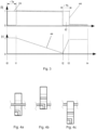
- Fig.3 The timing of an injection molding cycle is determined by Fig.3 .
- the rotary drive R of both the extruder screw 24 (in dotted line) and the injection screw 44 (in dashed line) is shown.
- the value “0” means that the corresponding drive is switched off and "1" means that the drive is switched on, but this does not mean that the drives have to be operated at the same rotation speed.
- the lower area of the Fig.3 shows the stroke of the injection screw, where the value "1" means that the injection screw 44 is in its front position, such as immediately after the injection process, and with the value "0" the injection screw is in the retracted position, in which a volume for the melt to be injected is created between the front end of the screw and the injection nozzle 49.
- the extruder screw 24 is started at time t0 and the melt is produced, mixed and homogenized in the extruder.
- the valve 30 can be closed.
- the valve 30 can be moved to the pass-through position at time t1 so that the melt can be discharged into the injection unit 40.
- the drive of the injection screw 44 is started, resulting in a time offset of the switch-on times ⁇ Ta of both screws.
- the injection screw is in its front position.
- both the extruder and injection screws are driven and melt is generated, and the injection screw 44 is moved into the retracted position and the melt collects in front of the injection screw 44 for the next injection process.
- a sufficient amount of melt has been generated for the injection movement taking place in the time range from t2 to t3.
- the extruder screw 24 is stopped and the lifting drive 143 of the injection unit 40 is activated.
- the injection screw has advanced to its front position and the injection of the plastic into the injection mold has ended, so that the rotary drive of the injection screw 44 can be stopped. There is thus a time offset of ⁇ Tb between the switching off of the two rotary drives.
- the rotary drive of the extruder screw is switched off at the same time as the lifting drive of the injection screw 44 is switched on, but alternatively the extruder screw can only be switched off at time t2', so that in the period t2 to t2' the lifting drive of the injection screw 44 and the rotary drive of the extruder screw are activated simultaneously and melt continues to be fed into the injection unit during the injection process of the plastic into the tool.
- the melt inlet 48 is provided in the rear area of the injection unit, i.e. away from the injection nozzle, and there is a lower pressure there than in the front area.
- the injection process is finished and the rotary drives of the injection screw 44 and the extruder screw are switched off during the curing and cooling time of the melt in the injection mold.
- the molded plastic workpiece is removed from the mold.
- the next injection molding cycle can begin, so that time t4 is identical to t0 of the next cycle.
- the extruder screw 24 can be reactivated during the cooling time, i.e. the range from t3 to t4, and produce melt for the next cycle, thereby reducing the cycle time.
- a holding pressure is preferably applied in the time period t3 to t4 via the stroke of the injection screw to compensate for the shrinkage of the injected plastic.
- the injection molding compounder is particularly suitable for applications where different materials are to be mixed together. Since the mixing takes place in both the extruder and the injection unit, the respective residence and mixing times and their extent in both of these units are reduced and overall, with good mixing, the thermal and mechanical stress on the materials is reduced.
- Suitable materials include a mixture of polycarbonate (PC) and acrylonitrile-butadiene-styrene (ABS), which is very sensitive to long-term temperature influences and high temperatures.
- PC polycarbonate
- ABS acrylonitrile-butadiene-styrene
- PP polypropylene
- talc 20% talc
- the impact strength can be increased by adding glass fibers or other fibers.
- the shortened residence time of the melt in each of these units reduces the mechanical stress on the fibers and reduces the risk of fiber breakage, thus increasing the strength of the molded part produced.
- a stable (lightweight) material can be produced by adding peroxide crosslinkers to polyethylene PE.
- Various types of fibers can be used as fibers, such as glass fibers, carbon fibers or natural fibers.
- the usual average residence time of the plastic is 2 to 6 minutes and the combined total residence time in the injection molding compounder can be reduced due to the better mixing within the extruder. Residence times that are too long can cause thermal and thermo-oxidative material damage.
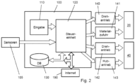
- the injection molding compounder comprises a computer unit or a programmable logic controller PLC 100 or is connected to it.
- the computer unit 100 comprises a control unit 120 which receives various input values via an input module 110, which is provided with a keyboard and a control screen, via various sensors 105 and/or via a memory module 130 and uses these to determine setpoints for the rotary drive 140 of the extruder 20 and the rotary drive 142 and the lifting drive 143 of the injection unit 40.
- Other existing setpoint generators such as for temperature control or the material supply for the extruder, are not discussed in more detail for the sake of brevity and clarity.
- Specifications for the operation of the injection molding compounder and in particular for switching the drives 140, 142 or 143 on and off can be entered directly via the input module 110.
- the sensors can act as a monitoring unit and detect and report blockages in the filling openings or signs of such and control the compounder accordingly.
- the extruder 20 can be operated with a bottom feed.
- the material feed 141 i.e. the dosing device of the extruder, determines the throughput of the extruder by limiting the material input via the hopper 22 with a feeding valve (not shown).
- This mode of operation differs from the overfeed mode, in which the material is fed "with a full hopper”. With bottom feed, the direct connection between the extruder screw speed and the throughput is eliminated. This makes it possible to control the preparation, e.g. the homogenization of the material in the extruder, via the extruder screw speed.
- injection units are generally not bottom fed. In this described mode of operation of the injection compounder, both advantages can be combined.
- one type of material can be fed in from a hopper 22, or several dosing stations can be provided which are operated in a coordinated manner so that a mixture is created when the material is filled into the extruder, or an additive, such as a dye or reinforcing fibers, is mixed into one or more plastic materials.
- control unit 120 can regulate the material feed 141 depending on the measured conditions, such as the filling level of the injection unit 40 or a time control.
- the dead time i.e. the delay from the control to the change in the material flow into the injection unit 40, must be taken into account, so that alternatively and/or additionally, a control of the rotary drive 140 of the extruder unit 20 can be used to increase the feed rate into the injection unit.
- the control unit 120 is set up to regulate the rotary drive 140 of the extruder to the nominal speed within 3 seconds (or max. 5s). This is an accelerated start-up compared to conventionally used start-up ramps of approx. 10s.
- the shutdown ramp i.e. the braking of the extruder to a standstill, has the same values or lower. According to one embodiment, these times can be used in particular with a cycle time of approx. 30s for an injection process.
- the storage module 130 can also have a database that contains empirical values for controlling the injection molding compounder depending on different materials or material combinations.
- the empirical values can, for example, include data that the viscosity of a first material composition A is lower than that of another material composition B and can therefore contain changed time specifications for the drives. For example, with a lower viscosity, it is easier to introduce additional material into the injection unit during the injection process and the time period t2 to t2' can therefore be selected to be longer than with a less viscous material composition. Accordingly, the times t1, t2 or t3 in particular are stored in a database for different material compositions.
- the operating parameters of the injection molding compounder can be calculated from the values stored in the database depending on different system variables such as the size, design or delivery volume of the extruder or injection unit, the desired or required temperature profiles or the size/mass of the injection molded part to be produced.
- the control unit preferably also has a memory function for storing operating parameters in the database so that the user can enter values via the input module 110 and recall them at a later time to control the injection molding compounder.
- the computer unit 100 can act as a stand-alone controller to drive and control both the injection unit 40 and the extruder.
- a controller already present on the injection unit 40 or the extruder unit 20 can be used to generate setpoints for the other unit 40, 20.
- control unit 120 is connected to the Internet 190.
- remote maintenance of the injection molding compounder via this connection, i.e. to read out parameters about the operating state and transmit them to a central control point, evaluate them there and send new target values and control conditions or algorithms to the control unit.
- a central database with advantageous operating conditions and machine settings in relation to special materials or material mixtures for the injection molding compounder can be provided at a location with access to the Internet (web server).
- the control unit 120 accesses this web server, reads out these advantageous or recommended operating conditions and stores them in the internal database 130 in order to be able to subsequently suggest them to the user as setting parameters.
- Fig.4 consists of the figures Fig. 4a, 4b and 4c , which schematically show different control states of the valve 30, which is preferably a heated 3-way valve.
- the extruder side is shown on the left and the injection unit side on the right, so that in the conveying process described above the melt is guided from left to right through the valve.
- This state is shown in Fig. 4a shown.
- Fig. 4c shows the valve in the closed state.
- This can be useful during the plasticizing phase of the plastic in the extruder 20 in order to be able to control the valve in this state, for example in the period from t0 to t1 (see Fig.3 ) to prevent the conveyance of insufficiently homogenized melt to the injection unit 40.
- the valve 30 can be brought into the discharge position, which in Fig. 4b
- the valve 30 can thus be used as a start-up valve and can also be used as a safety valve in the event of overpressure.
- the injection molding compounder and in particular the extruder 20, the transition of the pipe connection 35 from the extruder 20 to the injection unit 40 and the injection unit 40 is a system closed to the outside environment, although openings such as for degassing can be provided.
- the supply of the plastic components, the additives, the fillers and/or the fibers preferably takes place in the extruder and in the injection unit no further material is preferably added to the melt
- other materials such as glass fibers, natural fibers, peroxide crosslinkers, polylactic acid (PLA) or other plastic materials can also be added via one or more filling openings 42 of the injection unit. The latter is particularly advantageous if the added materials are (temperature) sensitive and possible damage in the extruder is to be avoided.
- the extruder described in the above exemplary embodiment is a single-screw extruder. It is known to those skilled in the art that, in general, a better mixing result can be achieved with a two- or multi-screw extruder than with a single-screw extruder. However, the multi-screw extruder also causes a higher mechanical load on the material, which causes a reduced chain length of the monomers (or polymers) or the fibers and can therefore cause a reduced component strength. Since the mixing result achieved by the (single-screw) extruder is further increased by the subsequent passage of the melt through the injection unit, a higher component quality can be achieved with the (single-screw) extruder than with a multi- (e.g. two-) screw extruder.
- a multi-screw extruder can also be used and the mixing result achieved there can be further increased in the downstream injection unit.
- the longitudinal alignment of the extruder is according to Fig.1 at a 90° angle to the injection unit.
- the melt is thus diverted by 90° at the inlet valve in the transition to the longitudinal direction of the injection unit and the material flow of the melt is swirled and an improvement in mixing is achieved which is gentle on the material.
- the mixing can be further increased by a further (not shown) diversion of the melt flow.
- the extruder can be aligned parallel to the injection unit so that the pipe connection connected to the extruder outlet is first diverted in the direction of the melt inlet 48 and the melt flow is subsequently diverted a second time in the injection unit.
- a comparable result can be achieved if the extruder is arranged perpendicular to the injection unit and with a height offset from it.
Landscapes
- Engineering & Computer Science (AREA)
- Mechanical Engineering (AREA)
- Manufacturing & Machinery (AREA)
- Injection Moulding Of Plastics Or The Like (AREA)
Claims (12)
- Mélangeur pour moulage par injection (1) présentant :une extrudeuse (20) avec au moins une vis sans fin d'extrudeuse (24) disposée dans un boîtier d'extrudeuse (21),une unité d'injection (40) avec une vis sans fin d'injection (44) disposée dans un boîtier d'injection (41), dans lequell'unité d'injection (40) présente une longueur opérationnelle (h) définie depuis la buse d'injection (49) de l'unité d'injection jusqu'à l'extrémité, située à distance de celle-ci, des spires de la vis sans fin d'injection (24), caractérisé en ce queest prévue sur le boîtier d'injection (41) une entrée pour matière fondue (48), qui est raccordée à une sortie (28) de l'extrudeuse (20), dans lequel l'entrée pour matière fondue (48) est située à une distance de la buse d'injection (49) qui est supérieure à un tiers de la longueur opérationnelle (h), et dans lequel une soupape est disposée entre la sortie (28) de l'extrudeuse (20) et l'entrée pour matière fondue (48) de l'unité d'injection (40),dans lequel la soupape est une soupape à trois voies, laquelle guide en variante la matière fondue dans l'unité d'injection ou la fait sortir dans l'environnement, et laquelle comprend en supplément l'état de la soupape fermée.
- Mélangeur pour moulage par injection (1) selon la revendication 1, caractérisé en ce que la soupape est une soupape de surpression ou une soupape pouvant être commandée.
- Mélangeur pour moulage par injection (1) selon la revendication 1 ou 2, dans lequel l'extrudeuse (20) présente exactement une vis sans fin d'extrudeuse (24).
- Mélangeur pour moulage par injection selon l'une quelconque des revendications précédentes,
caractérisé en ce que l'entrée pour matière fondue (48) est située à une distance de la buse d'injection (49) qui est supérieure à la moitié de la longueur opérationnelle (h) et est située de manière préférée à une distance de la buse d'injection (49) qui est supérieure à deux tiers de la longueur opérationnelle (h). - Mélangeur pour moulage par injection (1) selon l'une quelconque des revendications précédentes, présentant en outre une commande (120) qui est mise au point pour activer et désactiver l'entraînement (140) de la vis sans fin d'extrudeuse (24) en fonction de la phase de cycle d'une opération d'injection, dans lequel un laps de temps de l'entraînement (140) activé de la vis sans fin d'extrudeuse (24) et un laps de temps de l'entraînement non activé de la vis sans fin d'extrudeuse sont prévus en particulier à l'intérieur du cycle de l'opération d'injection.
- Mélangeur pour moulage par injection (1) selon l'une quelconque des revendications précédentes, dans lequel une commande est prévue pour activer et désactiver ou pour commander ou pour réguler l'entraînement de la vis sans fin d'extrudeuse (24) en fonction d'un moment prédéfini à l'intérieur de la phase de cycle d'une opération d'injection et/ou du degré de remplissage de l'unité d'injection, dans lequel la commande est mise au point de préférence pour réguler le flux volumique de la matière fondue refoulé par l'extrudeuse (20) sur l'unité d'extrudeuse (40) en fonction d'un écart d'un degré de remplissage de consigne, prédéfini en fonction de la phase d'injection, de l'unité d'injection (40) par rapport à un degré de remplissage réel mesuré de l'unité d'injection (40).
- Mélangeur pour moulage par injection selon l'une quelconque des revendications précédentes, dans lequel la commande est mise au point pour commander ou pour réguler de manière sous-alimentée l'amenée de matériau dans l'extrudeuse (20), dans lequel des valeurs de mesure de l'état de remplissage de l'unité d'injection (40) sont prévues en particulier pour la commande.
- Mélangeur pour moulage par injection selon l'une quelconque des
revendications précédentes, présentant une commande (120), qui est mise au point pour activer et désactiver l'entraînement rotatif (142) de la vis sans fin d'injection (44) et l'entraînement rotatif (140) de la vis sans fin d'extrudeuse (24), dans lequel un départ anticipé (ΔTa) ou un retard ou une simultanéité sont prévus par rapport à l'activation de l'entraînement rotatif (142) de la vis sans fin d'injection (44) ou par rapport à la course d'injection de la vis sans fin d'injection (44) pour l'activation de l'entraînement rotatif (140) de la vis sans fin d'extrudeuse (24) et en particulier un départ anticipé (ΔTb) ou un retard ou une simultanéité sont prévus par rapport à la désactivation de l'entraînement rotatif (142) de la vis sans fin d'injection (44) pour la désactivation de l'entraînement rotatif de la vis sans fin d'extrudeuse (24). - Mélangeur pour moulage par injection selon la revendication 5 ou 6 avec un module d'entrée (110) et/ou un module de mémorisation (130) pour entrer et/ou pour mémoriser des paramètres de fonctionnement pour les entraînements (140, 142, 143) de la vis sans fin d'injection (44) et de la vis sans fin d'extrudeuse (24) de sorte que la vis sans fin d'injection (44) et la vis sans fin d'extrudeuse (24) peuvent fonctionner avec un décalage temporel ou de manière synchrone l'une par rapport à l'autre à l'intérieur d'un cycle d'injection en fonction de différents matériaux ou de différentes combinaisons de matériaux de la matière fondue.
- Mélangeur pour moulage par injection selon l'une quelconque des revendications précédentes, dans lequel la sortie de l'extrudeuse (20) est raccordée à l'entrée pour matière fondue (48) de l'unité d'injection (40) par l'intermédiaire d'un raccordement tubulaire étanche à la pression ou à la matière fondue, et/ou dans lequel
l'extrudeuse (20) est mise au point pour refouler de la matière fondue synthétique vers l'unité d'injection (40) par la vis sans fin d'extrudeuse (24) et dans lequel aucun autre élément en particulier n'est prévu à cet effet pour le refoulement, comme des pistons, des pompes, des vis sans fin, pour l'utilisation de la force de gravité ou similaire. - Mélangeur pour moulage par injection selon l'une quelconque des revendications précédentes, dans lequel la durée d'un cycle des opérations d'injection peut être sous-divisée en de nombreux moments quelconques ou en de nombreux laps de temps, dans lequel il est prévu lors de la commande (120) du mélangeur pour moulage par injection qu'à chacun de ces moments, le flux volumique du raccordement tubulaire (35) est constant sur chacun de ses emplacements entre la sortie de l'extrudeuse et l'unité d'injection.
- Procédé pour fabriquer une pièce moulée par injection avec un mélangeur pour moulage par injection selon l'une quelconque des revendications précédentes, avec :l'amenée d'un ou de plusieurs matériaux pour moulage par injection à une extrudeuse,la fabrication d'une matière fondue par la fusion et/ou le mélange d'un ou des plusieurs matériaux de moulage par injection dans l'extrudeuse,l'amenée de la matière fondue par une ouverture d'entrée d'une unité d'injection dans l'unité d'injection,le guidage de la matière fondue dans l'unité d'injection (40) en direction d'une buse d'injection (49) raccordée à un outil pour moulage par injection (50),dans lequel une vis sans fin d'injection (44) de l'unité d'injection (40) présente une longueur opérationnelle (w) définie sur la longueur axiale des spires de la vis sans fin d'extrudeuse et l'ouverture d'entrée (48) est disposée de telle manière sur l'unité d'injection (40) que la matière fondue est guidée au moins sur un tiers de la longueur de spire (w) le long des spires de la vis sans fin d'injection (44).
Priority Applications (1)
| Application Number | Priority Date | Filing Date | Title |
|---|---|---|---|
| EP20160097.0A EP3677400B1 (fr) | 2012-02-17 | 2013-02-18 | Mélangeur pour moulage |
Applications Claiming Priority (2)
| Application Number | Priority Date | Filing Date | Title |
|---|---|---|---|
| DE201210101280 DE102012101280A1 (de) | 2012-02-17 | 2012-02-17 | Spritzgießcompounder |
| PCT/EP2013/053212 WO2013121049A1 (fr) | 2012-02-17 | 2013-02-18 | Mélangeur pour moulage par injection |
Related Child Applications (2)
| Application Number | Title | Priority Date | Filing Date |
|---|---|---|---|
| EP20160097.0A Division-Into EP3677400B1 (fr) | 2012-02-17 | 2013-02-18 | Mélangeur pour moulage |
| EP20160097.0A Division EP3677400B1 (fr) | 2012-02-17 | 2013-02-18 | Mélangeur pour moulage |
Publications (3)
| Publication Number | Publication Date |
|---|---|
| EP2814654A1 EP2814654A1 (fr) | 2014-12-24 |
| EP2814654B1 EP2814654B1 (fr) | 2020-04-29 |
| EP2814654B2 true EP2814654B2 (fr) | 2024-04-24 |
Family
ID=47750649
Family Applications (2)
| Application Number | Title | Priority Date | Filing Date |
|---|---|---|---|
| EP13706216.2A Active EP2814654B2 (fr) | 2012-02-17 | 2013-02-18 | Mélangeur pour moulage par injection et procédé |
| EP20160097.0A Active EP3677400B1 (fr) | 2012-02-17 | 2013-02-18 | Mélangeur pour moulage |
Family Applications After (1)
| Application Number | Title | Priority Date | Filing Date |
|---|---|---|---|
| EP20160097.0A Active EP3677400B1 (fr) | 2012-02-17 | 2013-02-18 | Mélangeur pour moulage |
Country Status (3)
| Country | Link |
|---|---|
| EP (2) | EP2814654B2 (fr) |
| DE (1) | DE102012101280A1 (fr) |
| WO (1) | WO2013121049A1 (fr) |
Families Citing this family (7)
| Publication number | Priority date | Publication date | Assignee | Title |
|---|---|---|---|---|
| DE102013218193A1 (de) * | 2013-09-11 | 2015-03-12 | Hp Pelzer Holding Gmbh | Compounder-Spritzgieß-Einheit |
| AT523150B1 (de) | 2019-11-28 | 2021-06-15 | Engel Austria Gmbh | Verfahren zur Beeinflussung einer Rückstaulänge und/oder einer Schneckenrücklaufgeschwindigkeit |
| AT526444A1 (de) | 2022-08-18 | 2024-03-15 | Engel Austria Gmbh | Plastifiziereinheit für eine Formgebungsmaschine |
| CN116618601B (zh) * | 2023-05-29 | 2024-03-12 | 伯乐智能装备股份有限公司 | 一种高效率双阶双注射的轻合金混合成型装置及工艺 |
| DE102023003635A1 (de) | 2023-09-07 | 2025-03-13 | Exipnos GmbH | Spritzgießcompounder |
| DE102024000241B4 (de) | 2024-01-17 | 2026-01-08 | Exipnos GmbH | Spritzgießcompounder und Verfahren zu dessen Herstellung sowie Einsatz und dessen Verwendung |
| CN119748792A (zh) * | 2025-03-03 | 2025-04-04 | 克劳斯玛菲机械(中国)有限公司 | 一种混炼注塑装置、注塑机及方法 |
Citations (20)
| Publication number | Priority date | Publication date | Assignee | Title |
|---|---|---|---|---|
| DE2355187A1 (de) † | 1972-11-06 | 1974-05-22 | Nissei Plastics Ind Co | Entlueftete spritzgussvorrichtung |
| DE3432263A1 (de) † | 1983-09-30 | 1985-04-18 | Netstal-Maschinen AG, Näfels | Schnecken-plastifizier- und foerdereinrichtung einer kunststoff-spritzgiessmaschine |
| EP0321742A1 (fr) † | 1987-12-04 | 1989-06-28 | Plastmachines Gelderland Gmbh Deutschland | Dispositif pour la régénération de matière thermoplastique |
| DE3840293A1 (de) † | 1988-11-30 | 1990-05-31 | Werner & Pfleiderer | Verfahren zum entfernen von verunreinigungen aus polymeren kunststoffen und vorrichtung zur durchfuehrung des verfahrens |
| EP0169231B1 (fr) † | 1984-01-10 | 1990-06-06 | Wavin B.V. | Procede et appareil de moulage par injection de produits en pvc |
| DE19611608A1 (de) † | 1995-03-24 | 1996-10-10 | Toshiba Machine Co Ltd | Verfahren und Gerät zum Anlegen eines Programmprofils zur Steuerung der Injektionsgeschwindigkeit von Spritzgießmaschinen |
| DE19718174A1 (de) † | 1996-04-30 | 1997-11-06 | Nissei Plastics Ind Co | Vorrichtung und Steuerverfahren zum Vorplastizier-Spritzgießen |
| DE19646394C1 (de) † | 1996-11-07 | 1998-04-30 | Roehm Gmbh | Extrusionsanlage und Verfahren zur Extrusion mit minimierten Farbwechselzeiten |
| WO1999041056A1 (fr) † | 1998-02-17 | 1999-08-19 | Cincinnati Milacron Inc. | Unite d'injection electrique a deux etages |
| DE10156522A1 (de) † | 2001-11-16 | 2003-06-05 | Krauss Maffei Kunststofftech | Spritzgießcompounder |
| DE10234228A1 (de) † | 2002-07-27 | 2004-02-19 | Berstorff Gmbh | Anfahrventil für einen Extruder, insbesondere eines Zweischneckenextruder |
| EP1440783A1 (fr) † | 2003-01-25 | 2004-07-28 | Motech GmbH Technology & Systems | Procédé de fabrication d'une bande d'emballage |
| DE102005007102A1 (de) † | 2005-02-16 | 2006-08-24 | Gala Industries, Inc. | Anfahrventil |
| EP1785253A1 (fr) † | 2004-08-19 | 2007-05-16 | The Japan Steel Works, Ltd. | Processus pour produire un objet moulé et appareil correspondant |
| DE102007012199A1 (de) † | 2007-03-14 | 2008-09-18 | Demag Ergotech Gmbh | Verfahren zum Betreiben einer Plastifizierungseinrichtung, z. B. eines Extruders oder einer Spritzgussmaschine |
| DE102007044617A1 (de) † | 2007-09-19 | 2009-04-02 | Kraussmaffei Technologies Gmbh | Compounder-Spritzgiessmaschine |
| WO2009147227A1 (fr) † | 2008-06-06 | 2009-12-10 | Kraussmaffei Technologies Gmbh | Unité d'injection |
| EP2236266A1 (fr) † | 2007-12-27 | 2010-10-06 | Sumitomo Heavy Industries, LTD. | Injecteur |
| DE202009011114U1 (de) † | 2009-08-14 | 2010-12-30 | Gala Industries Inc. | Granuliervorrichtung sowie Anfahrventil hierfür |
| DE202011106715U1 (de) † | 2011-10-12 | 2012-01-19 | Maag Pump Systems Gmbh | Vorrichtung zum Verteilen einer Kunststoffschmelze |
Family Cites Families (10)
| Publication number | Priority date | Publication date | Assignee | Title |
|---|---|---|---|---|
| CH445838A (de) | 1965-09-16 | 1967-10-31 | Buehler Ag Geb | Schnecken-Spritzgiessmaschine |
| JPS5751437B2 (fr) | 1974-06-05 | 1982-11-01 | ||
| JPS5751437A (en) | 1980-09-11 | 1982-03-26 | Nissei Plastics Ind Co | Method and device for controlling measurement in injection molding machine with preplasticizing device |
| ATE53335T1 (de) * | 1984-01-10 | 1990-06-15 | Wavin Bv | Verfahren und vorrichtung zum spritzgiessen von pvc-produkten. |
| US5653534A (en) * | 1994-10-12 | 1997-08-05 | Sumitomo Chemical Company, Limited | Screw apparatus and method for supplying reinforcing fiber-containing molten resin using the apparatus |
| JPH09123241A (ja) | 1995-10-27 | 1997-05-13 | Sodick Co Ltd | スクリュプリプラ式射出成形装置の射出制御方法 |
| DE10118486B4 (de) | 2001-04-12 | 2009-08-13 | Sumitomo (Shi) Demag Plastics Machinery Gmbh | Spritzeinheit für Spritzgießmaschinen mit kontinuierlich arbeitender Plastifiziereinheit |
| JP4390789B2 (ja) | 2006-08-02 | 2009-12-24 | 宏平 澤 | 混練部及び射出部を有する一体化装置 |
| DE102007042808B3 (de) | 2007-09-07 | 2009-04-02 | Kraussmaffei Technologies Gmbh | Spritzeinheit mit kontinuierlich betreibbarer Plastifiziereinheit |
| JP4699492B2 (ja) | 2008-04-14 | 2011-06-08 | 株式会社日本製鋼所 | 成形体の製造装置および製造方法 |
-
2012
- 2012-02-17 DE DE201210101280 patent/DE102012101280A1/de not_active Ceased
-
2013
- 2013-02-18 EP EP13706216.2A patent/EP2814654B2/fr active Active
- 2013-02-18 EP EP20160097.0A patent/EP3677400B1/fr active Active
- 2013-02-18 WO PCT/EP2013/053212 patent/WO2013121049A1/fr not_active Ceased
Patent Citations (20)
| Publication number | Priority date | Publication date | Assignee | Title |
|---|---|---|---|---|
| DE2355187A1 (de) † | 1972-11-06 | 1974-05-22 | Nissei Plastics Ind Co | Entlueftete spritzgussvorrichtung |
| DE3432263A1 (de) † | 1983-09-30 | 1985-04-18 | Netstal-Maschinen AG, Näfels | Schnecken-plastifizier- und foerdereinrichtung einer kunststoff-spritzgiessmaschine |
| EP0169231B1 (fr) † | 1984-01-10 | 1990-06-06 | Wavin B.V. | Procede et appareil de moulage par injection de produits en pvc |
| EP0321742A1 (fr) † | 1987-12-04 | 1989-06-28 | Plastmachines Gelderland Gmbh Deutschland | Dispositif pour la régénération de matière thermoplastique |
| DE3840293A1 (de) † | 1988-11-30 | 1990-05-31 | Werner & Pfleiderer | Verfahren zum entfernen von verunreinigungen aus polymeren kunststoffen und vorrichtung zur durchfuehrung des verfahrens |
| DE19611608A1 (de) † | 1995-03-24 | 1996-10-10 | Toshiba Machine Co Ltd | Verfahren und Gerät zum Anlegen eines Programmprofils zur Steuerung der Injektionsgeschwindigkeit von Spritzgießmaschinen |
| DE19718174A1 (de) † | 1996-04-30 | 1997-11-06 | Nissei Plastics Ind Co | Vorrichtung und Steuerverfahren zum Vorplastizier-Spritzgießen |
| DE19646394C1 (de) † | 1996-11-07 | 1998-04-30 | Roehm Gmbh | Extrusionsanlage und Verfahren zur Extrusion mit minimierten Farbwechselzeiten |
| WO1999041056A1 (fr) † | 1998-02-17 | 1999-08-19 | Cincinnati Milacron Inc. | Unite d'injection electrique a deux etages |
| DE10156522A1 (de) † | 2001-11-16 | 2003-06-05 | Krauss Maffei Kunststofftech | Spritzgießcompounder |
| DE10234228A1 (de) † | 2002-07-27 | 2004-02-19 | Berstorff Gmbh | Anfahrventil für einen Extruder, insbesondere eines Zweischneckenextruder |
| EP1440783A1 (fr) † | 2003-01-25 | 2004-07-28 | Motech GmbH Technology & Systems | Procédé de fabrication d'une bande d'emballage |
| EP1785253A1 (fr) † | 2004-08-19 | 2007-05-16 | The Japan Steel Works, Ltd. | Processus pour produire un objet moulé et appareil correspondant |
| DE102005007102A1 (de) † | 2005-02-16 | 2006-08-24 | Gala Industries, Inc. | Anfahrventil |
| DE102007012199A1 (de) † | 2007-03-14 | 2008-09-18 | Demag Ergotech Gmbh | Verfahren zum Betreiben einer Plastifizierungseinrichtung, z. B. eines Extruders oder einer Spritzgussmaschine |
| DE102007044617A1 (de) † | 2007-09-19 | 2009-04-02 | Kraussmaffei Technologies Gmbh | Compounder-Spritzgiessmaschine |
| EP2236266A1 (fr) † | 2007-12-27 | 2010-10-06 | Sumitomo Heavy Industries, LTD. | Injecteur |
| WO2009147227A1 (fr) † | 2008-06-06 | 2009-12-10 | Kraussmaffei Technologies Gmbh | Unité d'injection |
| DE202009011114U1 (de) † | 2009-08-14 | 2010-12-30 | Gala Industries Inc. | Granuliervorrichtung sowie Anfahrventil hierfür |
| DE202011106715U1 (de) † | 2011-10-12 | 2012-01-19 | Maag Pump Systems Gmbh | Vorrichtung zum Verteilen einer Kunststoffschmelze |
Non-Patent Citations (6)
| Title |
|---|
| Abschlussbericht "Förderprogramm Forschung fur die Umwelt im Bereich Integrierter Umweltschutz in der Kunststoff- und Kautschukindustie" † |
| Abschlussbericht Institut fur Kunststofftechnik der Univ Stuttgart (Bild 2.1,3.2, 5.12; S.4, 8-10, 59-61,79-80, Tab. 6 2) † |
| Johannaber / Michaeli. "Handbuch Spritzgießen". Munchen/Wien, Hanser, 2001 (Seiten 1041+1042 Bild 8 46) † |
| KraussMaffei-Prospekt "Direktverarbeitung mit der IMC-Baureihe - IMC-Spritzgießcompounder" Ausgabe 10/2001 † |
| KraussMaffei-Prospekt "Direktverarbeitung mit IMC-Spritzgießcompounder" Ausgabe 08/2007 † |
| Registratur der DE202011106715 U1 † |
Also Published As
| Publication number | Publication date |
|---|---|
| DE102012101280A1 (de) | 2013-08-22 |
| EP3677400C0 (fr) | 2025-10-22 |
| EP2814654A1 (fr) | 2014-12-24 |
| EP3677400B1 (fr) | 2025-10-22 |
| WO2013121049A1 (fr) | 2013-08-22 |
| EP3677400A1 (fr) | 2020-07-08 |
| EP2814654B1 (fr) | 2020-04-29 |
Similar Documents
| Publication | Publication Date | Title |
|---|---|---|
| EP2814654B2 (fr) | Mélangeur pour moulage par injection et procédé | |
| US5773042A (en) | Injection molding unit for long fiber-reinforced thermoplastic resin | |
| EP2101983B1 (fr) | Mélange de matière plastique avec des particules de bois | |
| DE69312246T2 (de) | Verfahren und Apparat zum kontinuierlichen Mischen von Kautschuk | |
| DE69524915T2 (de) | Mischvorrichtung und Verfahren zum Zuführen von faserverstärkte Kunststoffschmelze mit Gebrauch dieser Vorrichtung | |
| DE69005237T2 (de) | Extrudiervorrichtung und Verfahren zum Mischen von Fasern und thermoplastischen Kunststoffen. | |
| EP3730275B1 (fr) | Procédé de compoundage direct des compositions renforcées par des fibres pour la fabrication de pièces moulées en matière plastique et dispositif de compoundage direct | |
| EP1324869A1 (fr) | Extrudeuse a plusieurs vis et procede de preparation et / ou de traitement d'elastomeres a matiere de charge ajoutee | |
| EP3710220B1 (fr) | Procédé de fabrication de pièces moulées en matériau synthétique | |
| DE102007051923A1 (de) | Vorrichtung und Verfahren zur Verarbeitung polymerer Werkstoffe | |
| DE60211177T2 (de) | Misch- und knetvorrichtung für kunststoffe | |
| WO2004087391A1 (fr) | Procede et dispositif pour plastifier une matiere plastique | |
| DE2029353C3 (de) | Spritzgießvorrichtung | |
| EP2962824B1 (fr) | Procede de preparation d'une matiere contenant des fibres | |
| DE102019000610A1 (de) | Mischung von Kunststoff mit Holzpartikeln | |
| DE102006054204A1 (de) | Mischung von Kunststoff und Holzpartikeln | |
| DE102012112747B4 (de) | Plastifizierzylinder einer Spritzgießmaschine | |
| EP0633120B1 (fr) | Procédé et appareil pour la production d'objects moulés par soufflage | |
| DE102022106021A1 (de) | Plastifiziereinheit für eine Formgebungsmaschine und Verfahren zum Betreiben einer solchen | |
| DE102024000241B4 (de) | Spritzgießcompounder und Verfahren zu dessen Herstellung sowie Einsatz und dessen Verwendung | |
| AT526872B1 (de) | Formgebungsmaschine zum Herstellen von Formteilen | |
| AT526871B1 (de) | Formgebungsmaschine zum Herstellen von Formteilen | |
| WO2015140239A1 (fr) | Procédé de fabrication d'une pièce moulée en matière plastique et pièce moulée en matière plastique | |
| DE102023003635A1 (de) | Spritzgießcompounder | |
| DE4326585C1 (de) | Plastifizierschnecke für intermittierend arbeitende Spritzgießmaschinen |
Legal Events
| Date | Code | Title | Description |
|---|---|---|---|
| PUAI | Public reference made under article 153(3) epc to a published international application that has entered the european phase |
Free format text: ORIGINAL CODE: 0009012 |
|
| 17P | Request for examination filed |
Effective date: 20140903 |
|
| AK | Designated contracting states |
Kind code of ref document: A1 Designated state(s): AL AT BE BG CH CY CZ DE DK EE ES FI FR GB GR HR HU IE IS IT LI LT LU LV MC MK MT NL NO PL PT RO RS SE SI SK SM TR |
|
| AX | Request for extension of the european patent |
Extension state: BA ME |
|
| RIN1 | Information on inventor provided before grant (corrected) |
Inventor name: PUTSCH, PETER |
|
| DAX | Request for extension of the european patent (deleted) | ||
| STAA | Information on the status of an ep patent application or granted ep patent |
Free format text: STATUS: EXAMINATION IS IN PROGRESS |
|
| 17Q | First examination report despatched |
Effective date: 20190218 |
|
| RAP1 | Party data changed (applicant data changed or rights of an application transferred) |
Owner name: GUANGDONG YIZUMI PRECISION MACHINERY CO., LTD. |
|
| GRAP | Despatch of communication of intention to grant a patent |
Free format text: ORIGINAL CODE: EPIDOSNIGR1 |
|
| STAA | Information on the status of an ep patent application or granted ep patent |
Free format text: STATUS: GRANT OF PATENT IS INTENDED |
|
| INTG | Intention to grant announced |
Effective date: 20200206 |
|
| GRAS | Grant fee paid |
Free format text: ORIGINAL CODE: EPIDOSNIGR3 |
|
| GRAA | (expected) grant |
Free format text: ORIGINAL CODE: 0009210 |
|
| STAA | Information on the status of an ep patent application or granted ep patent |
Free format text: STATUS: THE PATENT HAS BEEN GRANTED |
|
| AK | Designated contracting states |
Kind code of ref document: B1 Designated state(s): AL AT BE BG CH CY CZ DE DK EE ES FI FR GB GR HR HU IE IS IT LI LT LU LV MC MK MT NL NO PL PT RO RS SE SI SK SM TR |
|
| REG | Reference to a national code |
Ref country code: GB Ref legal event code: FG4D Free format text: NOT ENGLISH |
|
| REG | Reference to a national code |
Ref country code: CH Ref legal event code: EP |
|
| REG | Reference to a national code |
Ref country code: DE Ref legal event code: R096 Ref document number: 502013014642 Country of ref document: DE |
|
| REG | Reference to a national code |
Ref country code: AT Ref legal event code: REF Ref document number: 1262621 Country of ref document: AT Kind code of ref document: T Effective date: 20200515 |
|
| REG | Reference to a national code |
Ref country code: IE Ref legal event code: FG4D Free format text: LANGUAGE OF EP DOCUMENT: GERMAN |
|
| REG | Reference to a national code |
Ref country code: NL Ref legal event code: MP Effective date: 20200429 |
|
| REG | Reference to a national code |
Ref country code: LT Ref legal event code: MG4D |
|
| PG25 | Lapsed in a contracting state [announced via postgrant information from national office to epo] |
Ref country code: PT Free format text: LAPSE BECAUSE OF FAILURE TO SUBMIT A TRANSLATION OF THE DESCRIPTION OR TO PAY THE FEE WITHIN THE PRESCRIBED TIME-LIMIT Effective date: 20200831 Ref country code: NO Free format text: LAPSE BECAUSE OF FAILURE TO SUBMIT A TRANSLATION OF THE DESCRIPTION OR TO PAY THE FEE WITHIN THE PRESCRIBED TIME-LIMIT Effective date: 20200729 Ref country code: IS Free format text: LAPSE BECAUSE OF FAILURE TO SUBMIT A TRANSLATION OF THE DESCRIPTION OR TO PAY THE FEE WITHIN THE PRESCRIBED TIME-LIMIT Effective date: 20200829 Ref country code: LT Free format text: LAPSE BECAUSE OF FAILURE TO SUBMIT A TRANSLATION OF THE DESCRIPTION OR TO PAY THE FEE WITHIN THE PRESCRIBED TIME-LIMIT Effective date: 20200429 Ref country code: SE Free format text: LAPSE BECAUSE OF FAILURE TO SUBMIT A TRANSLATION OF THE DESCRIPTION OR TO PAY THE FEE WITHIN THE PRESCRIBED TIME-LIMIT Effective date: 20200429 Ref country code: FI Free format text: LAPSE BECAUSE OF FAILURE TO SUBMIT A TRANSLATION OF THE DESCRIPTION OR TO PAY THE FEE WITHIN THE PRESCRIBED TIME-LIMIT Effective date: 20200429 Ref country code: GR Free format text: LAPSE BECAUSE OF FAILURE TO SUBMIT A TRANSLATION OF THE DESCRIPTION OR TO PAY THE FEE WITHIN THE PRESCRIBED TIME-LIMIT Effective date: 20200730 |
|
| PG25 | Lapsed in a contracting state [announced via postgrant information from national office to epo] |
Ref country code: HR Free format text: LAPSE BECAUSE OF FAILURE TO SUBMIT A TRANSLATION OF THE DESCRIPTION OR TO PAY THE FEE WITHIN THE PRESCRIBED TIME-LIMIT Effective date: 20200429 Ref country code: LV Free format text: LAPSE BECAUSE OF FAILURE TO SUBMIT A TRANSLATION OF THE DESCRIPTION OR TO PAY THE FEE WITHIN THE PRESCRIBED TIME-LIMIT Effective date: 20200429 Ref country code: RS Free format text: LAPSE BECAUSE OF FAILURE TO SUBMIT A TRANSLATION OF THE DESCRIPTION OR TO PAY THE FEE WITHIN THE PRESCRIBED TIME-LIMIT Effective date: 20200429 Ref country code: BG Free format text: LAPSE BECAUSE OF FAILURE TO SUBMIT A TRANSLATION OF THE DESCRIPTION OR TO PAY THE FEE WITHIN THE PRESCRIBED TIME-LIMIT Effective date: 20200729 |
|
| REG | Reference to a national code |
Ref country code: DE Ref legal event code: R026 Ref document number: 502013014642 Country of ref document: DE |
|
| PG25 | Lapsed in a contracting state [announced via postgrant information from national office to epo] |
Ref country code: AL Free format text: LAPSE BECAUSE OF FAILURE TO SUBMIT A TRANSLATION OF THE DESCRIPTION OR TO PAY THE FEE WITHIN THE PRESCRIBED TIME-LIMIT Effective date: 20200429 Ref country code: NL Free format text: LAPSE BECAUSE OF FAILURE TO SUBMIT A TRANSLATION OF THE DESCRIPTION OR TO PAY THE FEE WITHIN THE PRESCRIBED TIME-LIMIT Effective date: 20200429 |
|
| PLBI | Opposition filed |
Free format text: ORIGINAL CODE: 0009260 |
|
| PG25 | Lapsed in a contracting state [announced via postgrant information from national office to epo] |
Ref country code: DK Free format text: LAPSE BECAUSE OF FAILURE TO SUBMIT A TRANSLATION OF THE DESCRIPTION OR TO PAY THE FEE WITHIN THE PRESCRIBED TIME-LIMIT Effective date: 20200429 Ref country code: ES Free format text: LAPSE BECAUSE OF FAILURE TO SUBMIT A TRANSLATION OF THE DESCRIPTION OR TO PAY THE FEE WITHIN THE PRESCRIBED TIME-LIMIT Effective date: 20200429 Ref country code: RO Free format text: LAPSE BECAUSE OF FAILURE TO SUBMIT A TRANSLATION OF THE DESCRIPTION OR TO PAY THE FEE WITHIN THE PRESCRIBED TIME-LIMIT Effective date: 20200429 Ref country code: EE Free format text: LAPSE BECAUSE OF FAILURE TO SUBMIT A TRANSLATION OF THE DESCRIPTION OR TO PAY THE FEE WITHIN THE PRESCRIBED TIME-LIMIT Effective date: 20200429 Ref country code: SM Free format text: LAPSE BECAUSE OF FAILURE TO SUBMIT A TRANSLATION OF THE DESCRIPTION OR TO PAY THE FEE WITHIN THE PRESCRIBED TIME-LIMIT Effective date: 20200429 Ref country code: IT Free format text: LAPSE BECAUSE OF FAILURE TO SUBMIT A TRANSLATION OF THE DESCRIPTION OR TO PAY THE FEE WITHIN THE PRESCRIBED TIME-LIMIT Effective date: 20200429 |
|
| PLBI | Opposition filed |
Free format text: ORIGINAL CODE: 0009260 |
|
| PLBI | Opposition filed |
Free format text: ORIGINAL CODE: 0009260 |
|
| 26 | Opposition filed |
Opponent name: ARBURG GMBH + CO. KG Effective date: 20201228 |
|
| PLAX | Notice of opposition and request to file observation + time limit sent |
Free format text: ORIGINAL CODE: EPIDOSNOBS2 |
|
| PG25 | Lapsed in a contracting state [announced via postgrant information from national office to epo] |
Ref country code: SK Free format text: LAPSE BECAUSE OF FAILURE TO SUBMIT A TRANSLATION OF THE DESCRIPTION OR TO PAY THE FEE WITHIN THE PRESCRIBED TIME-LIMIT Effective date: 20200429 Ref country code: PL Free format text: LAPSE BECAUSE OF FAILURE TO SUBMIT A TRANSLATION OF THE DESCRIPTION OR TO PAY THE FEE WITHIN THE PRESCRIBED TIME-LIMIT Effective date: 20200429 |
|
| 26 | Opposition filed |
Opponent name: KRAUSSMAFFEI TECHNOLOGIES GMBH Effective date: 20210127 |
|
| 26 | Opposition filed |
Opponent name: ENGEL AUSTRIA GMBH Effective date: 20210129 |
|
| PG25 | Lapsed in a contracting state [announced via postgrant information from national office to epo] |
Ref country code: SI Free format text: LAPSE BECAUSE OF FAILURE TO SUBMIT A TRANSLATION OF THE DESCRIPTION OR TO PAY THE FEE WITHIN THE PRESCRIBED TIME-LIMIT Effective date: 20200429 |
|
| PLBB | Reply of patent proprietor to notice(s) of opposition received |
Free format text: ORIGINAL CODE: EPIDOSNOBS3 |
|
| PLAB | Opposition data, opponent's data or that of the opponent's representative modified |
Free format text: ORIGINAL CODE: 0009299OPPO |
|
| R26 | Opposition filed (corrected) |
Opponent name: ENGEL AUSTRIA GMBH Effective date: 20210129 |
|
| PG25 | Lapsed in a contracting state [announced via postgrant information from national office to epo] |
Ref country code: HU Free format text: LAPSE BECAUSE OF FAILURE TO SUBMIT A TRANSLATION OF THE DESCRIPTION OR TO PAY THE FEE WITHIN THE PRESCRIBED TIME-LIMIT; INVALID AB INITIO Effective date: 20130218 |
|
| PG25 | Lapsed in a contracting state [announced via postgrant information from national office to epo] |
Ref country code: CY Free format text: LAPSE BECAUSE OF FAILURE TO SUBMIT A TRANSLATION OF THE DESCRIPTION OR TO PAY THE FEE WITHIN THE PRESCRIBED TIME-LIMIT Effective date: 20200429 |
|
| PLAB | Opposition data, opponent's data or that of the opponent's representative modified |
Free format text: ORIGINAL CODE: 0009299OPPO |
|
| R26 | Opposition filed (corrected) |
Opponent name: ARBURG GMBH + CO. KG Effective date: 20201228 |
|
| REG | Reference to a national code |
Ref country code: CH Ref legal event code: PK Free format text: TITEL |
|
| PUAH | Patent maintained in amended form |
Free format text: ORIGINAL CODE: 0009272 |
|
| STAA | Information on the status of an ep patent application or granted ep patent |
Free format text: STATUS: PATENT MAINTAINED AS AMENDED |
|
| 27A | Patent maintained in amended form |
Effective date: 20240424 |
|
| AK | Designated contracting states |
Kind code of ref document: B2 Designated state(s): AL AT BE BG CH CY CZ DE DK EE ES FI FR GB GR HR HU IE IS IT LI LT LU LV MC MK MT NL NO PL PT RO RS SE SI SK SM TR |
|
| REG | Reference to a national code |
Ref country code: DE Ref legal event code: R102 Ref document number: 502013014642 Country of ref document: DE |
|
| PG25 | Lapsed in a contracting state [announced via postgrant information from national office to epo] |
Ref country code: MK Free format text: LAPSE BECAUSE OF FAILURE TO SUBMIT A TRANSLATION OF THE DESCRIPTION OR TO PAY THE FEE WITHIN THE PRESCRIBED TIME-LIMIT Effective date: 20200429 |
|
| REG | Reference to a national code |
Ref country code: CH Ref legal event code: PK Free format text: DIE PUBLIKATION VOM 27.03.2024 WURDE AM 24.04.2024 IRRTUEMLICHERWEISE ERNEUT PUBLIZIERT. LA PUBLICATION DU 27.03.2024 A ETE REPUBLIEE PAR ERREUR LE 24.04.2024. LA PUBBLICAZIONE DEL 27.03.2024 E STATA ERRONEAMENTE RIPUBBLICATA IL 24.04.2024. |
|
| PG25 | Lapsed in a contracting state [announced via postgrant information from national office to epo] |
Ref country code: TR Free format text: LAPSE BECAUSE OF FAILURE TO SUBMIT A TRANSLATION OF THE DESCRIPTION OR TO PAY THE FEE WITHIN THE PRESCRIBED TIME-LIMIT Effective date: 20200429 |
|
| PG25 | Lapsed in a contracting state [announced via postgrant information from national office to epo] |
Ref country code: MT Free format text: LAPSE BECAUSE OF FAILURE TO SUBMIT A TRANSLATION OF THE DESCRIPTION OR TO PAY THE FEE WITHIN THE PRESCRIBED TIME-LIMIT Effective date: 20200429 |
|
| REG | Reference to a national code |
Ref country code: CH Ref legal event code: U11 Free format text: ST27 STATUS EVENT CODE: U-0-0-U10-U11 (AS PROVIDED BY THE NATIONAL OFFICE) Effective date: 20260301 |
|
| PGFP | Annual fee paid to national office [announced via postgrant information from national office to epo] |
Ref country code: LU Payment date: 20260217 Year of fee payment: 14 |
|
| PGFP | Annual fee paid to national office [announced via postgrant information from national office to epo] |
Ref country code: GB Payment date: 20260219 Year of fee payment: 14 |
|
| PGFP | Annual fee paid to national office [announced via postgrant information from national office to epo] |
Ref country code: MC Payment date: 20260217 Year of fee payment: 14 |
|
| PGFP | Annual fee paid to national office [announced via postgrant information from national office to epo] |
Ref country code: IE Payment date: 20260218 Year of fee payment: 14 Ref country code: DE Payment date: 20260226 Year of fee payment: 14 |
|
| PGFP | Annual fee paid to national office [announced via postgrant information from national office to epo] |
Ref country code: AT Payment date: 20260216 Year of fee payment: 14 |
|
| PGFP | Annual fee paid to national office [announced via postgrant information from national office to epo] |
Ref country code: BE Payment date: 20260218 Year of fee payment: 14 |
|
| PGFP | Annual fee paid to national office [announced via postgrant information from national office to epo] |
Ref country code: FR Payment date: 20260223 Year of fee payment: 14 |
|
| PGFP | Annual fee paid to national office [announced via postgrant information from national office to epo] |
Ref country code: CZ Payment date: 20260206 Year of fee payment: 14 Ref country code: CH Payment date: 20260301 Year of fee payment: 14 |