EP2814701B1 - Dispositif de freinage d'un véhicule et procédé permettant de faire fonctionner un dispositif de freinage d'un véhicule - Google Patents
Dispositif de freinage d'un véhicule et procédé permettant de faire fonctionner un dispositif de freinage d'un véhicule Download PDFInfo
- Publication number
- EP2814701B1 EP2814701B1 EP12810200.1A EP12810200A EP2814701B1 EP 2814701 B1 EP2814701 B1 EP 2814701B1 EP 12810200 A EP12810200 A EP 12810200A EP 2814701 B1 EP2814701 B1 EP 2814701B1
- Authority
- EP
- European Patent Office
- Prior art keywords
- brake
- primary piston
- force
- component
- transmission component
- Prior art date
- Legal status (The legal status is an assumption and is not a legal conclusion. Google has not performed a legal analysis and makes no representation as to the accuracy of the status listed.)
- Not-in-force
Links
Images
Classifications
-
- B—PERFORMING OPERATIONS; TRANSPORTING
- B60—VEHICLES IN GENERAL
- B60T—VEHICLE BRAKE CONTROL SYSTEMS OR PARTS THEREOF; BRAKE CONTROL SYSTEMS OR PARTS THEREOF, IN GENERAL; ARRANGEMENT OF BRAKING ELEMENTS ON VEHICLES IN GENERAL; PORTABLE DEVICES FOR PREVENTING UNWANTED MOVEMENT OF VEHICLES; VEHICLE MODIFICATIONS TO FACILITATE COOLING OF BRAKES
- B60T13/00—Transmitting braking action from initiating means to ultimate brake actuator with power assistance or drive; Brake systems incorporating such transmitting means, e.g. air-pressure brake systems
- B60T13/10—Transmitting braking action from initiating means to ultimate brake actuator with power assistance or drive; Brake systems incorporating such transmitting means, e.g. air-pressure brake systems with fluid assistance, drive, or release
- B60T13/12—Transmitting braking action from initiating means to ultimate brake actuator with power assistance or drive; Brake systems incorporating such transmitting means, e.g. air-pressure brake systems with fluid assistance, drive, or release the fluid being liquid
- B60T13/14—Transmitting braking action from initiating means to ultimate brake actuator with power assistance or drive; Brake systems incorporating such transmitting means, e.g. air-pressure brake systems with fluid assistance, drive, or release the fluid being liquid using accumulators or reservoirs fed by pumps
- B60T13/142—Systems with master cylinder
-
- B—PERFORMING OPERATIONS; TRANSPORTING
- B60—VEHICLES IN GENERAL
- B60T—VEHICLE BRAKE CONTROL SYSTEMS OR PARTS THEREOF; BRAKE CONTROL SYSTEMS OR PARTS THEREOF, IN GENERAL; ARRANGEMENT OF BRAKING ELEMENTS ON VEHICLES IN GENERAL; PORTABLE DEVICES FOR PREVENTING UNWANTED MOVEMENT OF VEHICLES; VEHICLE MODIFICATIONS TO FACILITATE COOLING OF BRAKES
- B60T7/00—Brake-action initiating means
- B60T7/02—Brake-action initiating means for personal initiation
- B60T7/04—Brake-action initiating means for personal initiation foot actuated
- B60T7/042—Brake-action initiating means for personal initiation foot actuated by electrical means, e.g. using travel or force sensors
-
- B—PERFORMING OPERATIONS; TRANSPORTING
- B60—VEHICLES IN GENERAL
- B60T—VEHICLE BRAKE CONTROL SYSTEMS OR PARTS THEREOF; BRAKE CONTROL SYSTEMS OR PARTS THEREOF, IN GENERAL; ARRANGEMENT OF BRAKING ELEMENTS ON VEHICLES IN GENERAL; PORTABLE DEVICES FOR PREVENTING UNWANTED MOVEMENT OF VEHICLES; VEHICLE MODIFICATIONS TO FACILITATE COOLING OF BRAKES
- B60T11/00—Transmitting braking action from initiating means to ultimate brake actuator without power assistance or drive or where such assistance or drive is irrelevant
- B60T11/10—Transmitting braking action from initiating means to ultimate brake actuator without power assistance or drive or where such assistance or drive is irrelevant transmitting by fluid means, e.g. hydraulic
- B60T11/16—Master control, e.g. master cylinders
- B60T11/20—Tandem, side-by-side, or other multiple master cylinder units
- B60T11/203—Side-by-side configuration
-
- B—PERFORMING OPERATIONS; TRANSPORTING
- B60—VEHICLES IN GENERAL
- B60T—VEHICLE BRAKE CONTROL SYSTEMS OR PARTS THEREOF; BRAKE CONTROL SYSTEMS OR PARTS THEREOF, IN GENERAL; ARRANGEMENT OF BRAKING ELEMENTS ON VEHICLES IN GENERAL; PORTABLE DEVICES FOR PREVENTING UNWANTED MOVEMENT OF VEHICLES; VEHICLE MODIFICATIONS TO FACILITATE COOLING OF BRAKES
- B60T13/00—Transmitting braking action from initiating means to ultimate brake actuator with power assistance or drive; Brake systems incorporating such transmitting means, e.g. air-pressure brake systems
- B60T13/10—Transmitting braking action from initiating means to ultimate brake actuator with power assistance or drive; Brake systems incorporating such transmitting means, e.g. air-pressure brake systems with fluid assistance, drive, or release
- B60T13/58—Combined or convertible systems
- B60T13/588—Combined or convertible systems both fluid and mechanical assistance or drive
-
- B—PERFORMING OPERATIONS; TRANSPORTING
- B60—VEHICLES IN GENERAL
- B60T—VEHICLE BRAKE CONTROL SYSTEMS OR PARTS THEREOF; BRAKE CONTROL SYSTEMS OR PARTS THEREOF, IN GENERAL; ARRANGEMENT OF BRAKING ELEMENTS ON VEHICLES IN GENERAL; PORTABLE DEVICES FOR PREVENTING UNWANTED MOVEMENT OF VEHICLES; VEHICLE MODIFICATIONS TO FACILITATE COOLING OF BRAKES
- B60T13/00—Transmitting braking action from initiating means to ultimate brake actuator with power assistance or drive; Brake systems incorporating such transmitting means, e.g. air-pressure brake systems
- B60T13/74—Transmitting braking action from initiating means to ultimate brake actuator with power assistance or drive; Brake systems incorporating such transmitting means, e.g. air-pressure brake systems with electrical assistance or drive
- B60T13/745—Transmitting braking action from initiating means to ultimate brake actuator with power assistance or drive; Brake systems incorporating such transmitting means, e.g. air-pressure brake systems with electrical assistance or drive acting on a hydraulic system, e.g. a master cylinder
-
- B—PERFORMING OPERATIONS; TRANSPORTING
- B60—VEHICLES IN GENERAL
- B60T—VEHICLE BRAKE CONTROL SYSTEMS OR PARTS THEREOF; BRAKE CONTROL SYSTEMS OR PARTS THEREOF, IN GENERAL; ARRANGEMENT OF BRAKING ELEMENTS ON VEHICLES IN GENERAL; PORTABLE DEVICES FOR PREVENTING UNWANTED MOVEMENT OF VEHICLES; VEHICLE MODIFICATIONS TO FACILITATE COOLING OF BRAKES
- B60T8/00—Arrangements for adjusting wheel-braking force to meet varying vehicular or ground-surface conditions, e.g. limiting or varying distribution of braking force
- B60T8/32—Arrangements for adjusting wheel-braking force to meet varying vehicular or ground-surface conditions, e.g. limiting or varying distribution of braking force responsive to a speed condition, e.g. acceleration or deceleration
- B60T8/34—Arrangements for adjusting wheel-braking force to meet varying vehicular or ground-surface conditions, e.g. limiting or varying distribution of braking force responsive to a speed condition, e.g. acceleration or deceleration having a fluid pressure regulator responsive to a speed condition
- B60T8/38—Arrangements for adjusting wheel-braking force to meet varying vehicular or ground-surface conditions, e.g. limiting or varying distribution of braking force responsive to a speed condition, e.g. acceleration or deceleration having a fluid pressure regulator responsive to a speed condition including valve means of the relay or driver controlled type
Definitions
- the invention relates to a braking device for a vehicle. Furthermore, the invention relates to methods for operating a braking device of a vehicle.
- the master cylinder has a markable as a first piston rod piston and a tubular second piston.
- the first piston is slidable by a predetermined piston travel through the second piston into a first pressure chamber of the master cylinder.
- An entrainment device formed on the second piston is intended to cause the first piston, after overcoming the predetermined piston travel, to take along the second piston.
- the first piston and the second piston should be able to act on the first pressure chamber of the master cylinder after overcoming the predetermined piston travel together. In addition to be acted upon by means of a floating piston on a second pressure chamber of the master cylinder.
- the invention provides a braking device for a vehicle having the features of claim 1, a braking system having the features of claim 10, a method for operating a braking device of a vehicle having the features of claim 12 and a method for operating a braking device of a vehicle having the features of claim 15.
- a first idle travel between the force-free initial position of the brake force transmission component and the first primary piston component an effect of a driver braking force exerted on the brake actuating element / brake pedal can be reduced / prevented.
- This can also be described in such a way that, in spite of the driver braking force exerted on the brake actuating element, braking of the driver into the master brake cylinder can be easily reduced / prevented.
- a second free travel between the booster force transmission component present in its force-free initial position and the second primary piston component can prevent a booster force exerted on the booster force transmission component from automatically causing braking into the master brake cylinder.
- a Einbrems Koch of the force exerted by the actuator means on the amplifier power transmission component amplifier power can be reduced by the formation of the second idle travel.
- the brake power transmission component present in its force-free starting position can be spaced apart from the first primary piston component by the first idle travel which is greater than a distance between the booster force transmission component present in its force-free initial position and the second primary piston component.
- the distance between the booster force transmission component in its dead center position and the second primary piston member may be zero or nonzero.
- the present in their force-free initial position amplifier power transmission component to the second idle path not equal to zero the second primary piston component, which is greater than a distance between the present in their force-free initial position brake power transmission component and the first primary piston component.
- the distance between the braking force transmission component in its force-free starting position and the first primary piston component may be zero or non-zero in this case.
- an artificially extended idle travel can be formed between the booster force transmission component present in its force-free starting position and the second primary piston component, which can be used for recuperation, without this being associated with exceeding a setpoint deceleration of the vehicle specified by the driver.
- the brake device may have a fluid exchange device, through which in a first operating mode, a liquid between the first primary piston chamber and the second primary piston chamber is replaceable, and via which in the presence of the liquid exchange device in a second operating mode, a fluid exchange between the first primary piston chamber and the second primary piston chamber is prevented.
- a fluid exchange device By switching / controlling the liquid exchange device thus the primary Einbremsvolumen the master cylinder can be varied.
- the driver and the actuator device may brake into a total primary piston chamber of the first primary piston chamber and the second primary piston chamber with a larger total volume.
- the liquid exchange device by switching / controlling the liquid exchange device to the second mode of operation, it can be determined that only the driver enters the first primary piston chamber, i. H. in a primary Einbremsvolumen with only the first volume of the primary piston chamber, can brake.
- the switching / control of the liquid exchange device into the second operating mode is in particular in a mechanical fallback mode, i. H. in case of failure / functional impairment of the actuator device, advantageous.
- the master cylinder may additionally have a secondary piston chamber and one between the first primary piston chamber and the secondary piston chamber having adjustable secondary piston.
- the advantages of the present invention are therefore also applicable to a tandem master cylinder.
- the brake device in which at least the brake power transmission component present in its force-free starting position is spaced apart from the first primary piston component by the first idle travel, which can only be closed from a minimum driver brake force, can have an actuator control device by means of which the Aktor responded is controlled so that at a driver braking force under the minimum driver braking force a predetermined target amplifier power by the driven actuator so exercisable on the second primary piston component, that the second volume of the second primary piston chamber by means of the displaced second primary piston component reducible and a liquid transfer from the second Primary piston chamber in at least one wheel brake cylinder for establishing a form in the at least one wheel brake cylinder can be triggered.
- the brake device can have an actuator control device by means of which the Aktor diagnosed is controlled so that at a driver braking force under the minimum driver braking force a predetermined target amplifier power by the driven actuator so exercisable on the second primary piston component, that the second volume of the second primary piston chamber by means of the displaced second primary piston component reducible and a liquid transfer from the second Primary
- the actuator control device may additionally be designed to specify the desired amplifier power taking into account at least one state of a brake system component and / or a traffic situation.
- a pre-pressure in the at least one wheel brake cylinder can be established even before the driver directly brakes into the master brake cylinder.
- the desired amplifier power can be predetermined or be predeterminable by means of the actuator control device such that a clearance between at least one rest torque-free brake caliper and a brake disk can be closed by means of the established pre-pressure.
- the clearance between the at least one rest torque-free caliper and the cooperating brake disc can be closed in a simple manner by means of the established form. This leads to a significantly improved braking comfort for the driver.
- the brake device may have a generator control device, which at least at an amplifier power below the minimum amplifier power is designed to control a generator so that by means of the generator, a generator braking torque is equal to zero exercisable.
- the braking effect of the amplifier power which is prevented by means of the second idle travel, can thus be used for faster charging of a vehicle battery.
- the brake system can have at least one rest torque-free brake caliper. Since the clearance between the at least one brake caliper and the brake disk cooperating therewith can already be closed by means of building up a form even before the driver directly brakes by means of the driver braking force, the brake system can combine the advantages of good ease of use with reduced fuel consumption and lower pollutant emission.
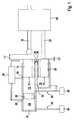
- Fig. 1 shows a schematic representation of a first embodiment of the braking device.
- FIG. 1 schematically illustrated brake device is in a vehicle, preferably in a vehicle equipped with a generator, used.
- the braking device may be arrangeable as a compact unit in a braking system of the vehicle.
- the brake device may be formed as a non-separated formed subunit of the brake system.
- the brake device has a master cylinder 10 with a first primary piston chamber 12, wherein a first volume of the first primary piston chamber 12 is variable by means of an adjustable first primary piston member 14.
- a braking force transmission component 16 of the braking device such as an output rod, can be arranged (directly or indirectly) on a (not shown) brake actuating element such that at least one driver braking force can be transmitted via the braking force transmission component 16 to the first adjustable primary piston component 14 contacted by the braking force transmission component 16.
- the brake operating element may be, for example, a brake pedal.
- the feasibility of the brake actuator or the braking force transmission component 16 is not limited to the here enumerated embodiments.
- the master cylinder 10 also has a second primary piston chamber 18 whose second volume is variable by means of an adjustable second primary piston component 20.
- the brake device also has an amplifier power transmission component 22, to which an actuator (not shown) can be arranged (directly or indirectly) such that an amplifier power provided by the actuator at least partially via the amplifier force transmission component 22 to the second adjustable primary piston component 20 contacted by the booster force transmission component 22 is transferable.
- the actuator device can be, for example, an engine and / or a hydraulic system of a brake booster.
- the first primary piston component 14 and / or the second primary piston component 20 may be formed, for example, as a rod piston component. It should be noted, however, that the formability of a primary piston member 14 and 20 is not limited to a rod piston. Likewise, the first primary piston component 14 and / or the second primary piston component 2 can each be constructed from a plurality of subcomponents. Also, the shape of the first primary piston member 14 and the second primary piston member 20 can be fixed with a large design freedom.
- the force-free starting position of the brake-force transmission component 16 can be understood to mean a position thereof in which the brake-force-transmitting component 16 is present when no driver braking force is transmitted to it.
- the force-free initial position of the booster force transmission component 22 is preferably to be understood as meaning a position thereof in which the booster force transmission component 22 is present at zero amplifier power or deactivation of the actuator device.
- the force-free initial positions of the power transmission components 16 and 22 are to be understood as positions in which the power transmission components 16 and 22 provided that no driver braking force is exerted on the brake actuator and no amplifier power is provided by means of the actuator device.
- the formation of the first idle path L1 not equal to zero has the advantage that, despite a driver braking force not equal to zero, which causes an adjustment of the braking force transmission component 16, a braking of the driver braking force in the master cylinder 10 is prevented up to a certain minimum driver braking force.
- a braking of the amplifier power in the master cylinder 10 is suppressed to a minimum amplifier power is exceeded. This can be exploited for a variety of advantageous uses, which will be described in more detail below.
- the brake power transfer component 16 may be in its zero-force starting position about a first non-zero Leerweg L1 of the first primary piston member 14, which is greater than a distance (zero or non-zero) between the booster force transmission component 22 in its force-free starting position and the second primary piston member 20 , As will be explained in more detail below, this allows the formation of a pre-pressure in the first primary piston chamber 12 even before a direct braking of the driver in the master cylinder 10th
- the booster force transmission component 22 may be in its non-energized starting position about a second non-zero L2 spaced from the second primary piston member 20 which is greater than zero (zero or non-zero) between the brake power transmission component 16 in its dead center position and the first primary piston member 14 is.
- a large second Leerweg L2 is associated with the advantage that, despite an amplifier power not equal to zero and at least slightly out of their force-free initial position adjusted amplifier power transmission component 22 no additional brake pressure is built up by adjusting the second primary piston member 20.
- the braking effect attributable to the persistence of the second primary piston component 20 in a position with a maximum second volume can be used to insert a generator without a vehicle deceleration predetermined by the driver is exceeded.
- a comparatively large second Leerweg L2 can be used for faster charging a vehicle battery.
- the first primary piston component 14 is still adjustable into the master cylinder 10 even in the presence of the actuator device in a deactivated / function-impaired state.
- the advantageous split design of the master cylinder 10 and the use of two primary piston components 14 and 20 is additionally associated with the advantage that when a functional impairment of the actuator / brake booster device by means of actuation of the brake actuator only the first primary piston member 14 is to move while the second primary piston member 20th remains in a certain position despite the operation of the brake actuator by the driver.
- the driver does not have to brake with the total braking surface equal to the sum of the boundary surfaces F1 + F2, but only with a reduced Einbrems Design equal to the first boundary surface F1, in the first primary piston chamber 12 of the master cylinder 10.
- the driver braking force causes a larger pressure build-up in the master brake cylinder 10.
- the functional impairment of Aktor worn / brake booster device due to the advantageous design of the master cylinder 10 and the use of two primary piston components 14 and 20 at least partially via an increased Einbremskraft-brake pressure transmission in a simple manner compensated.
- a secondary piston chamber 24 and between the first primary piston chamber 12 and the secondary piston chamber 24 adjustable secondary piston 26 have.
- the secondary piston 26 may be formed in particular as a floating piston.
- the first primary piston chamber 12, the second primary piston chamber 18 and / or the secondary piston chamber 24 may be connected via at least one brake fluid exchange port 28, such as a sniffer bore, to a brake fluid reservoir 30 / brake fluid reservoir.
- at least a partial partition wall 32 may be formed, which separates the first volume of the first primary piston chamber 12 from the second volume of the second primary piston chamber 18.
- each of the primary piston components 14 and 20 may be assigned its own opening 34 and 36.
- at least one sealing element such as a sealing ring, leakage of liquid can be prevented despite an adjustment of the respective primary piston component 14 and 20 from the respective opening 34 and 36.
- the braking device has a liquid exchange device 38, via which in the presence of the liquid exchange device 38 in a first operating mode, a liquid between the first primary piston chamber 12 and the second primary piston chamber 18 is interchangeable.
- the liquid exchange device 38 from the first operating mode at least in a second operating mode can be controlled / switched, wherein in the presence of the liquid exchange device 38 in the second mode of operation, a liquid exchange between the first primary piston chamber 12 and the second primary piston chamber 18 is prevented by means of the liquid exchange device 38.
- the liquid exchange device 38 may be, for example, a first brake circuit 38 with at least one wheel brake cylinder 40, to which the primary piston chambers 12 and 18 are connected.
- a (not shown) component of the first brake circuit 38 can be used.
- the secondary piston chamber 24 can also be connected to a second brake circuit 42 with at least one wheel brake cylinder 44.
- a valve formed in the partial partition wall 32 can also be used as the fluid exchange device 38.
- the brake device may have an amplifier body 46, which is arranged between the actuator device and the booster force transmission component 22 in such a way that the booster force can be transmitted via the booster body 46 to the booster force transmission component 22.
- the booster body 46 may also contact the brake power transmission component 16 in at least one position.
- at least a portion of the boosting force may also be transmitted via the brake power transfer component 16 to the first primary piston member 14 for assisting the rider in force when braking into the master cylinder 10. This ensures advantageous brake operation comfort for the driver.
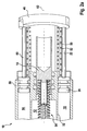
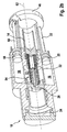
- Fig. 2a and 2 B show schematic partial views of a second embodiment of the braking device.
- FIG. 2a and 2 B schematically reproduced embodiment has the components already described above. On a more accurate marking of the first empty way and the second empty way is at the Fig. 2a and 2 B waived.
- Fig. 2a and 2 B are also cooperating with the brake force transmission component 16 first return spring 50, cooperating with the booster body 46 second return spring 52 and arranged in the first primary piston chamber 12 spring system 54, via which the first primary piston member 14 is supported on the secondary piston member 26 is shown.
- a third primary piston chamber 56 the third volume by means of an adjustable third primary piston member 58 is variable.
- a further amplifier power transmission component 60 at least part of the amplifier power can also be transmitted from the amplifier body 46 to the third primary piston component 58.
- the second primary piston chamber 18 and the third primary piston chamber 56 may in particular be formed symmetrically with respect to a central longitudinal axis 62 of the first primary piston chamber 12.
- the development of the master cylinder 10 described here is optional.
- the brake devices described in the above paragraphs may also have an actuator control device and / or a generator control device in an advantageous development.
- the interaction of the brake devices with the actuator control device is advantageous, provided that at least the present in their force-free initial position brake power transmission component 16 to the first idle path is not equal to zero spaced from the first primary piston member 14, which is closed only from a minimum driver brake force.
- the actuator control device is advantageous if the present in their force-free initial position brake power transmission component 16 by the first idle path is not equal to zero spaced from the first primary piston member 14, which is greater than a distance between the present in their force-free initial position booster force transmission component 22 and the second primary piston member 20th is.
- the actuator control device is designed so that by means of the actuator control device, the actuator device is controlled so that at a driver braking force under the minimum driver braking force a predetermined desired amplifier power by means of the driven actuator device so on the second primary piston component 20 is exercised that the second volume of the second primary piston chamber 18 can be reduced by means of the displaced second primary piston component 20, and a fluid transfer from the second primary piston chamber 18 into the at least one wheel brake cylinder can be triggered at least into the at least one wheel brake cylinder to build up a primary pressure.
- the actuator control device is additionally designed to specify the desired amplifier power taking into account at least one state of a brake system component and / or a traffic situation.
- the setpoint amplifier power can be predetermined by means of the actuator control device such that a clearance between at least one rest torque-free brake caliper and a brake disk can be closed by means of the established pre-pressure.
- the braking devices described above may in particular be a subunit of a brake system which Has at least one rest torque-free caliper.
- the interaction of the above-described brake devices with a generator control device is advantageous if at least the present in their force-free initial position amplifier power transmission component 22 by the second idle path is not equal to zero spaced from the second primary piston member 20, which is closed only from a minimum amplifier power.
- the generator control device is advantageous if the present in their force-free initial position booster force transmission component 22 by the second idle path is not equal to zero spaced from the second primary piston member 20, which is greater than a distance between the present in their force-free initial position brake power transmission component 16 and the first primary piston component fourteenth is.
- the generator control device is at least at an amplifier power below the minimum amplifier power designed to control a generator so that by means of the generator, a generator braking torque is equal to zero exercisable.
- the actuator control device and / or the generator control device may in particular be designed to carry out the functions explained using the methods described below.
- the operation of the actuator control device and the generator control device which may be integrated in particular in a common electronics, and the resulting advantages, reference is therefore made to the following methods.
- Fig. 3 shows a flowchart for illustrating a first embodiment of the method for operating a braking device of a vehicle.
- That on the basis of Fig. 3 reproduced method is executable by means of a brake device with a master cylinder with a first primary piston chamber and a second primary piston chamber, a braking force transmission component, by means of which at least one driver brake force is transmitted to a first adjustable primary piston component contacted by the brake force transmission component such that a first volume of the first primary piston chamber is varied by means of the displaced first primary piston component, and an amplifier force transmission component with which an amplifier force provided by an actuator device at least partially so on the amplifier power transmission component contacted second adjustable primary piston component is transmitted, that a second volume of the second primary piston chamber is varied by means of the displaced second primary piston.
- the braking force transmission component is in its force-free starting position by a first idle path not equal to zero from the first primary piston component before, which is closed only from a minimum driver brake force.
- the method is also advantageous if the present in its force-free initial position brake power transmission component is present at the first free travel non-zero distance from the first primary piston component, which is greater than a distance between the present in their force-free initial position amplifier power transmission component and the second primary piston component.
- the method described here can be carried out, for example, by means of the braking devices described above. The feasibility of the method is not limited to a use of such a braking device.
- the method has at least one method step S1, in which an admission pressure is built up at least at least one wheel brake cylinder in spite of a driver braking force below the minimum driver braking force. This is done by applying a predetermined desired amplifier power by means of the actuator device.
- the at least partially transmitted to the second primary piston component target amplifier force causes a reduction of the second volume of the second primary piston chamber by means of the displaced second primary piston component and triggers a fluid transfer from the second primary piston chamber in the at least one wheel brake cylinder.
- an advantageous form in the at least one wheel brake cylinder is already at a start of a direct braking of the driver in the master cylinder.
- the method also has a method step S0, in which the desired amplifier power is predefined taking into account at least one state of a brake system component and / or a traffic situation.
- the desired amplifier power is predefined taking into account at least one state of a brake system component and / or a traffic situation.
- a traffic situation in which a rapid deceleration of the vehicle appears advantageous
- an advantageous pre-pressure can be built up even before a direct braking of the driver in the master cylinder.
- at least one state of a brake system component such as, for example, a functional impairment of a brake system component, may also be taken into account when specifying the desired amplifier power.
- the setpoint amplifier power is predetermined or fixed such that a clearance between at least one caliper, preferably a rest torque-free caliper, and a brake disc by means of the established form already before a direct braking of the driver in the Master cylinder is closed.
- a rest torque-free caliper has an increased clearance. You can also rewrite this so that no grinding of the pads of the caliper on the brake disc occurs in a rest torque-free caliper. In contrast occurs in a different caliper / non-residual torque caliper even when driving under non-actuation of the brake actuator, a grinding of the pads on the brake disc, which can cause a generally undesirable braking of the vehicle.
- the increased clearance of the rest torque-free caliper is associated with the advantage that no unwanted deceleration occurs during non-actuation of the brake actuator and thus driving the vehicle is already possible with a lower fuel consumption and a lower pollutant emission.
- a volume of the associated wheel brake cylinder which is necessary before a braking torque is effected, increased.
- a driver of a vehicle with restless calipers often has the impression of having a "long brake pedal," which is sometimes perceived as unsportsmanlike or uncomfortable. Therefore, many drivers reject the equipment of their vehicle with restless calipers despite the associated benefits in terms of lower fuel consumption and lower pollutant emissions.
- the construction of the admission pressure caused by the method step S1 causes a prefilling of the wheel brake cylinder, whereby the clearance can be overcome even before the driver directly brakes into the master brake cylinder.
- the driver of a vehicle the braking system is operated with the reproduced here method, thus has a normal brake feel / pedal feel even when equipped with rest torque-free calipers.
- the method described here thus combines the advantages of an advantageous brake feeling / pedal feeling with a reduced fuel consumption and a lower pollutant emission.
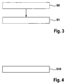
- Fig. 4 shows a flowchart for illustrating a second embodiment of the method for operating a braking device of a vehicle.
- the method can be carried out by means of a brake device with a master brake cylinder having a first primary piston chamber and a second primary piston chamber, a brake force transmission component, by means of which at least one driver brake force is transmitted to a contacted by the brake force transmission component first adjustable primary piston component so that a first volume of the first primary piston chamber by means of the displaced a booster force transmission component, by means of which an amplifier force provided by an actuator device is at least partially transmitted to a second variable primary piston component contacted by the booster force transmission component such that a second volume of the second primary piston chamber is varied by means of the displaced second primary piston component.
- At least the present in their force-free initial position amplifier power transmission component is spaced by a second idle path not equal to zero of the second primary piston component, which is closed only from a minimum amplifier power.
- the method is advantageous when the in its power-free initial position present amplifier power transmission component to the second idle path non-zero spaced from the second primary piston component is present, which is greater than a distance between the present in their force-free initial position brake power transmission component and the first primary piston component.
- the method described here can be carried out, for example, by means of the braking devices described above.
- the feasibility of the method is not limited to a use of such a braking device.
- the method has a method step S10, in which at least one amplifier power below the minimum amplifier power activates a generator for exerting a non-zero generator braking torque.
- the second free travel between the booster force transmission component and the second primary piston component can be used to reduce, in particular inhibit, a braking effect of the actuator device, and thus to use a generator for faster charging of a vehicle battery.
- the advantage is ensured that the driver can brake quickly and reliably directly into the master cylinder, and thus can cause a stoppage of the vehicle.
- the advantageous technology described in the above paragraphs enables a coupling of an operation of the actuator device and an actuation of the brake actuating element by the driver. At the same time, it is possible to decouple the driver from the braking system to a limited extent.
- blending between electric braking of a generator and hydraulic braking of a braking system equipped / operated with the advantageous technology is advantageously carried out.
- the blending may be performed so that the driver does not notice any difference between electric braking and hydraulic braking.
- an improvement of the fallback level can be achieved by freely setting a primary Einbremsvolumens at least between a total volume of the two primary piston chambers or only the first primary piston chamber, or the Einbrems formation.
Landscapes
- Engineering & Computer Science (AREA)
- Transportation (AREA)
- Mechanical Engineering (AREA)
- Physics & Mathematics (AREA)
- Fluid Mechanics (AREA)
- Braking Systems And Boosters (AREA)
- Regulating Braking Force (AREA)
- Transmission Of Braking Force In Braking Systems (AREA)
Claims (15)
- Appareil de freinage pour un véhicule, comprenant :un cylindre de frein principal (10) comprenant une première chambre de piston primaire (12), dont le premier volume peut être modifié au moyen d'un premier composant de piston primaire réglable (14) ;un composant de transfert de force de freinage (16), au niveau duquel peut être disposé directement ou indirectement un élément d'actionnement de frein, de telle sorte qu'au moins une force de freinage du conducteur puisse être transmise par le composant de transfert de force de freinage (16) au premier composant de piston primaire réglable (14) avec lequel vient en contact le composant de transfert de force de freinage (16) ; etun deuxième composant de piston primaire réglable (20) ;caractérisé en ce quele cylindre de frein principal (10) présente une deuxième chambre de piston primaire (18), dont le deuxième volume peut être modifié au moyen du deuxième composant de piston primaire réglable (20) ;l'appareil de freinage présentant un composant de transfert de force d'amplification (22) au niveau duquel peut être disposé directement ou indirectement un dispositif d'actionneur de telle sorte qu'une force d'amplification fournie par le dispositif d'actionneur puisse être transmise au moins en partie par le biais du composant de transfert de force d'amplification (22) au deuxième composant de piston primaire réglable (20) avec lequel vient en contact le composant de transfert de force d'amplification (22) ; etle composant de transfert de force de freinage (16) se trouvant dans sa position initiale sans force étant espacé d'une première course à vide (L1) différente de zéro du premier composant de piston primaire (14) et/ou le composant de transfert de force d'amplification (22) se trouvant dans sa position initiale sans force étant espacé d'une deuxième course à vide (L2) différente de zéro du deuxième composant de piston primaire (20).
- Appareil de freinage selon la revendication 1, dans lequel le composant de transfert de force de freinage (16) se trouvant dans sa position initiale sans force est espacé de la première course à vide (L1) différente de zéro du premier composant de piston primaire (14), laquelle est supérieure à une distance entre le composant de transfert de force d'amplification (22) se trouvant dans sa position initiale sans force et le deuxième composant de piston primaire (20).
- Appareil de freinage selon la revendication 1 ou 2, dans lequel le composant de transfert de force d'amplification (22) se trouvant dans sa position initiale sans force est espacé de la deuxième course à vide (L2) différente de zéro du deuxième composant de piston primaire (20), laquelle est supérieure à une distance entre le composant de transfert de force de freinage (16) se trouvant dans sa position initiale sans force et le premier composant de piston primaire (14).
- Appareil de freinage selon l'une quelconque des revendications précédentes, dans lequel l'appareil de freinage présente un dispositif d'échange de liquide (38) par le biais duquel, lorsque le dispositif d'échange de liquide (38) se trouve dans un premier mode de fonctionnement, un liquide peut être échangé entre la première chambre de piston primaire (12) et la deuxième chambre de piston primaire (18), et par le biais duquel, lorsque le dispositif d'échange de liquide (38) se trouve dans un deuxième mode de fonctionnement, un échange de liquide entre la première chambre de piston primaire (12) et la deuxième chambre de piston primaire (18) n'est pas possible.
- Appareil de freinage selon l'une quelconque des revendications précédentes, dans lequel le cylindre de frein principal (10) présente en outre une chambre de piston secondaire (24) et un piston secondaire (26) pouvant être déplacé entre la première chambre de piston primaire (12) et la chambre de piston secondaire (24).
- Appareil de freinage selon l'une quelconque des revendications précédentes, dans lequel au moins le composant de transfert de force de freinage (16) se trouvant dans sa position initiale sans force est espacé de la première course à vide (L1) différente de zéro du premier composant de piston primaire (14), lequel peut être fermé seulement à partir d'une force de freinage minimale du conducteur, et dans lequel l'appareil de freinage présente un dispositif de commande d'actionneur au moyen duquel le dispositif d'actionneur peut être commandé de telle sorte que dans le cas d'une force de freinage du conducteur inférieure à la force de freinage minimale du conducteur, une force d'amplification de consigne prédéfinie puisse être exercée au moyen du dispositif d'actionneur commandé sur le deuxième composant de piston primaire (20) de telle sorte que le deuxième volume de la deuxième chambre de piston primaire (18) puisse être réduit au moyen du deuxième composant de piston primaire déplacé (20) et qu'un transfert de liquide de la deuxième chambre de piston primaire (18) dans au moins un cylindre de frein de roue (40, 44) puisse être initié pour augmenter une pression pilote dans l'au moins un cylindre de frein de roue (40, 44).
- Appareil de freinage selon la revendication 6, dans lequel le dispositif de commande d'actionneur est en outre conçu pour prédéfinir la force d'amplification de consigne en tenant compte d'au moins un état d'un composant du système de freinage et/ou d'une situation de circulation.
- Appareil de freinage selon la revendication 6 ou 7, dans lequel la force d'amplification de consigne est prédéfinie, ou peut être prédéfinie au moyen du dispositif de commande d'actionneur de telle sorte qu'un jeu entre au moins un étrier de frein exempt de couple résiduel et un disque de frein puisse être fermé au moyen de la pression pilote augmentée.
- Appareil de freinage selon l'une quelconque des revendications précédentes, dans lequel au moins le composant de transfert de force d'amplification (22) se trouvant dans sa position initiale sans force est espacé de la deuxième course à vide (L2) différente de zéro du deuxième composant de piston primaire (20), lequel peut être fermé seulement à partir d'une force d'amplification minimale, et dans lequel l'appareil de freinage présente un dispositif de commande de générateur qui est conçu, au moins pour une force d'amplification en dessous de la force d'amplification minimale, pour commander un générateur de telle sorte qu'un couple de freinage de générateur différent de zéro puisse être exercé au moyen du générateur.
- Système de freinage comprenant un appareil de freinage selon l'une quelconque des revendications précédentes.
- Système de freinage selon la revendication 10, dans lequel le système de freinage présente au moins un étrier de frein exempt de couple résiduel.
- Procédé pour faire fonctionner un appareil de freinage d'un véhicule comprenant un cylindre de frein principal (10) comprenant une première chambre de piston primaire (12) et une deuxième chambre de piston primaire (18), un composant de transfert de force de freinage (16), au moyen duquel au moins une force de freinage du conducteur est transmise à un premier composant de piston primaire (14) réglable avec lequel vient en contact le composant de transfert de force de freinage (16) de telle sorte qu'un premier volume de la première chambre de piston primaire (12) soit modifié au moyen du premier composant de piston primaire réglé (14), et un composant de transfert de force d'amplification (22), au moyen duquel une force d'amplification fournie par un dispositif d'actionneur est transmise au moins en partie à un deuxième composant de piston primaire réglable (20) avec lequel vient en contact le composant de transfert de force d'amplification (22) de telle sorte qu'un deuxième volume de la deuxième chambre de piston primaire (18) soit modifié au moyen du deuxième composant de piston primaire réglé (20), au moins le composant de transfert de force de freinage (16) se trouvant dans sa position initiale sans force étant espacé d'une première course à vide (L1) différente de zéro du premier composant de piston primaire (14), lequel est fermé seulement à partir d'une force de freinage minimale du conducteur, comprenant l'étape suivante :augmentation d'une pression pilote dans au moins un cylindre de frein de roue (40, 44) dans le cas d'une force de freinage du conducteur en dessous de la force de freinage minimale du conducteur en exerçant une force d'amplification de consigne prédéfinie au moyen du dispositif d'actionneur pour initier une réduction du deuxième volume de la deuxième chambre de piston primaire (18) au moyen du deuxième composant de piston primaire réglé (20) et d'un transfert de liquide de la deuxième chambre de piston primaire (18) dans l'au moins un cylindre de frein de roue (40, 44) (S1).
- Procédé selon la revendication 12, dans lequel la force d'amplification de consigne est prédéfinie (S0) en tenant compte d'au moins un état d'un composant du système de freinage et/ou d'une situation de circulation.
- Procédé selon la revendication 12 ou 13, dans lequel la force d'amplification de consigne est prédéfinie de telle sorte qu'un jeu entre au moins un étrier de frein exempt de couple résiduel et un disque de frein soit fermé au moyen de la pression pilote augmentée.
- Procédé pour faire fonctionner un appareil de freinage d'un véhicule comprenant un cylindre de frein principal (10) comprenant une première chambre de piston primaire (12) et une deuxième chambre de piston primaire (18), un composant de transfert de force de freinage (16), au moyen duquel au moins une force de freinage du conducteur est transmise à un premier composant de piston primaire réglable (14) avec lequel vient en contact le composant de transfert de force de freinage (16) de telle sorte qu'un premier volume de la première chambre de piston primaire (12) soit modifié au moyen dû premier composant de piston primaire réglé (14), et un composant de transfert de force d'amplification (22), au moyen duquel une force d'amplification fournie par un dispositif d'actionneur est transmise au moins en partie à un deuxième composant de piston primaire réglable (20) avec lequel vient en contact le composant de transfert de force d'amplification (22) de telle sorte qu'un deuxième volume de la deuxième chambre de piston primaire (18) soit modifié au moyen du deuxième composant de piston primaire réglé (20), au moins le composant de transfert de force d'amplification (22) se trouvant dans sa position initiale sans force étant espacé d'une deuxième course à vide (L2) différente de zéro du deuxième composant de piston primaire (20), qui est seulement fermé à partir d'une force d'amplification minimale, comprenant l'étape suivante :activation d'un générateur pour exercer un couple de freinage de générateur différent de zéro au moins dans le cas d'une force d'amplification inférieure à la force d'amplification minimale (S10).
Applications Claiming Priority (2)
| Application Number | Priority Date | Filing Date | Title |
|---|---|---|---|
| DE102012202201A DE102012202201A1 (de) | 2012-02-14 | 2012-02-14 | Bremsgerät für ein Fahrzeug und Verfahren zum Betreiben eines Bremsgeräts eines Fahrzeugs |
| PCT/EP2012/075725 WO2013120562A1 (fr) | 2012-02-14 | 2012-12-17 | Dispositif de freinage d'un véhicule et procédé permettant de faire fonctionner un dispositif de freinage d'un véhicule |
Publications (2)
| Publication Number | Publication Date |
|---|---|
| EP2814701A1 EP2814701A1 (fr) | 2014-12-24 |
| EP2814701B1 true EP2814701B1 (fr) | 2016-05-11 |
Family
ID=47504908
Family Applications (1)
| Application Number | Title | Priority Date | Filing Date |
|---|---|---|---|
| EP12810200.1A Not-in-force EP2814701B1 (fr) | 2012-02-14 | 2012-12-17 | Dispositif de freinage d'un véhicule et procédé permettant de faire fonctionner un dispositif de freinage d'un véhicule |
Country Status (7)
| Country | Link |
|---|---|
| US (1) | US9604616B2 (fr) |
| EP (1) | EP2814701B1 (fr) |
| JP (1) | JP5977371B2 (fr) |
| KR (1) | KR20140129020A (fr) |
| CN (1) | CN104093610B (fr) |
| DE (1) | DE102012202201A1 (fr) |
| WO (1) | WO2013120562A1 (fr) |
Families Citing this family (5)
| Publication number | Priority date | Publication date | Assignee | Title |
|---|---|---|---|---|
| DE102014213727A1 (de) | 2014-07-15 | 2016-01-21 | Robert Bosch Gmbh | Hauptbremszylinder und Bremssystem für ein Fahrzeug |
| CN107284429A (zh) * | 2016-04-13 | 2017-10-24 | 史占彪 | 柱塞式增压泵 |
| JP6840947B2 (ja) * | 2016-07-21 | 2021-03-10 | 株式会社アドヴィックス | 車両の制動制御装置 |
| JP6604311B2 (ja) * | 2016-11-01 | 2019-11-13 | トヨタ自動車株式会社 | 排気管構造 |
| DE102017208685A1 (de) * | 2017-05-23 | 2018-11-29 | Robert Bosch Gmbh | Steuervorrichtung und Verfahren zum Betreiben eines elektromechanischen Bremskraftverstärkers eines Fahrzeugs |
Family Cites Families (9)
| Publication number | Priority date | Publication date | Assignee | Title |
|---|---|---|---|---|
| DE502004005089D1 (de) * | 2003-07-11 | 2007-11-08 | Continental Teves Ag & Co Ohg | Elektrohydraulische bremsanlage für kraftfahrzeuge |
| JP4497107B2 (ja) | 2006-03-02 | 2010-07-07 | トヨタ自動車株式会社 | ブレーキ制御装置 |
| DE102007016861A1 (de) * | 2007-04-10 | 2008-10-16 | Robert Bosch Gmbh | Bremskraftverstärker und Hilfskraftbremssystem für ein Fahrzeug |
| DE102009055117A1 (de) | 2009-12-22 | 2011-06-30 | Robert Bosch GmbH, 70469 | Hauptbremszylinder für eine hydraulische Fahrzeugbremsanlage und Verfahren zu ihrem Betrieb |
| DE102010003822B4 (de) * | 2010-04-09 | 2025-05-15 | Robert Bosch Gmbh | Bremskraftverstärker-Ankopplungsvorrichtung |
| DE102010038555B4 (de) | 2010-07-28 | 2017-01-26 | Robert Bosch Gmbh | Bremssystem für ein Fahrzeug und Verfahren zum Betreiben eines Bremssystems für ein Fahrzeug |
| JP5756275B2 (ja) * | 2010-11-01 | 2015-07-29 | 日産自動車株式会社 | 電動倍力装置 |
| US8496302B2 (en) * | 2011-09-23 | 2013-07-30 | Robert Bosch Gmbh | Brake booster |
| DE102011083827A1 (de) * | 2011-09-30 | 2013-04-04 | Robert Bosch Gmbh | Primärkolbenbaugruppe für einen Hauptbremszylinder eines Bremssystems eines Fahrzeugs, Herstellungsverfahren für ein Bremsgerät und Verfahren zum Betreiben eines Bremsgeräts |
-
2012
- 2012-02-14 DE DE102012202201A patent/DE102012202201A1/de not_active Withdrawn
- 2012-12-17 WO PCT/EP2012/075725 patent/WO2013120562A1/fr not_active Ceased
- 2012-12-17 CN CN201280069637.5A patent/CN104093610B/zh not_active Expired - Fee Related
- 2012-12-17 EP EP12810200.1A patent/EP2814701B1/fr not_active Not-in-force
- 2012-12-17 JP JP2014555108A patent/JP5977371B2/ja not_active Expired - Fee Related
- 2012-12-17 US US14/378,272 patent/US9604616B2/en not_active Expired - Fee Related
- 2012-12-17 KR KR1020147022663A patent/KR20140129020A/ko not_active Withdrawn
Also Published As
| Publication number | Publication date |
|---|---|
| EP2814701A1 (fr) | 2014-12-24 |
| JP5977371B2 (ja) | 2016-08-24 |
| DE102012202201A1 (de) | 2013-08-14 |
| US20150034438A1 (en) | 2015-02-05 |
| CN104093610A (zh) | 2014-10-08 |
| US9604616B2 (en) | 2017-03-28 |
| KR20140129020A (ko) | 2014-11-06 |
| JP2015509879A (ja) | 2015-04-02 |
| WO2013120562A1 (fr) | 2013-08-22 |
| CN104093610B (zh) | 2016-11-16 |
Similar Documents
| Publication | Publication Date | Title |
|---|---|---|
| DE102010038555B4 (de) | Bremssystem für ein Fahrzeug und Verfahren zum Betreiben eines Bremssystems für ein Fahrzeug | |
| EP2598385B1 (fr) | Dispositif de couplage pour relier un élément de commande de freinage à un maître-cylindre de frein et systeme de freinage avec un tel dispositif de couplage | |
| DE102013208703A1 (de) | Steuervorrichtung für ein rekuperatives Bremssystem eines Fahrzeugs und Verfahren zum Abbremsen eines Fahrzeugs | |
| EP2931576B1 (fr) | Procédé pour faire fonctionner un système de freinage d'un véhicule et dispositif de commande d'un système de freinage d'un véhicule | |
| EP2931572B1 (fr) | Procédé pour faire fonctionner un système de freinage d'un véhicule et dispositif de commande d'un système de freinage d'un véhicule | |
| EP2934973B1 (fr) | Système de freinage électrohydraulique pour véhicule et procédé de fonctionnement | |
| DE102010042363A1 (de) | Bremssystem für ein Fahrzeug und Verfahren zum Betreiben eines Bremssystems für ein Fahrzeug | |
| EP2688780B1 (fr) | Système de freinage et véhicule avec un tel système de freinage | |
| DE102014205431A1 (de) | Bremssystem für ein Fahrzeug | |
| DE102013216314A1 (de) | Bremsanlage für Kraftfahrzeuge und zugehöriges Betriebsverfahren | |
| DE102010038548B4 (de) | Bremssystem für ein Fahrzeug und Verfahren zum Betreiben eines Bremssystems für ein Fahrzeug | |
| DE102011075971A1 (de) | Steuervorrichtung für ein Bremssystem eines Fahrzeugs und Verfahren zum Betreiben eines Bremssystems eines Fahrzeugs | |
| EP2996912B1 (fr) | Dispositif de commande d'un système de freinage assisté autonome d'un véhicule et procédé permettant de faire fonctionner un système de freinage assisté autonome d'un véhicule | |
| DE102010042990A1 (de) | Bremssystem für ein Fahrzeug und Verfahren zum Betreiben eines Bremssystems eines Fahrzeugs | |
| DE102010040854A1 (de) | Hydraulisches Bremssystem sowie Verfahren zu dessen Betrieb | |
| EP2635471B1 (fr) | Servofrein et son procédé de fonctionnement | |
| DE112013007152T5 (de) | Fahrzeugbremsvorrichtung | |
| EP2814701B1 (fr) | Dispositif de freinage d'un véhicule et procédé permettant de faire fonctionner un dispositif de freinage d'un véhicule | |
| DE102010043203A1 (de) | Bremskraftverstärker und Verfahren zum Betrieb eines Bremskraftverstärkers | |
| DE102013216329A1 (de) | Verfahren und Vorrichtung zur Regelung eines Bremssystems | |
| EP2296948B1 (fr) | Servofrein pour un système de freinage de véhicule à moteur et système de freinage de véhicule à moteur correspondant | |
| DE102014215379B4 (de) | Bremssystem für ein Fahrzeug | |
| DE102019211236A1 (de) | Verfahren zum Ansteuern eines hydraulischen Bremssystems in einem Fahrzeug | |
| DE102014225587A1 (de) | Hydraulikaggregat für ein Bremssystem eines Fahrzeugs, Bremssystem für ein Fahrzeug und Verfahren zum Betreiben eines Bremssystems eines Fahrzeugs | |
| DE102008035180B4 (de) | Bremskrafterzeuger für eine hydraulische Kraftfahrzeugbremsanlage mit regenerativer Bremsfunktion |
Legal Events
| Date | Code | Title | Description |
|---|---|---|---|
| PUAI | Public reference made under article 153(3) epc to a published international application that has entered the european phase |
Free format text: ORIGINAL CODE: 0009012 |
|
| 17P | Request for examination filed |
Effective date: 20140915 |
|
| AK | Designated contracting states |
Kind code of ref document: A1 Designated state(s): AL AT BE BG CH CY CZ DE DK EE ES FI FR GB GR HR HU IE IS IT LI LT LU LV MC MK MT NL NO PL PT RO RS SE SI SK SM TR |
|
| AX | Request for extension of the european patent |
Extension state: BA ME |
|
| DAX | Request for extension of the european patent (deleted) | ||
| GRAP | Despatch of communication of intention to grant a patent |
Free format text: ORIGINAL CODE: EPIDOSNIGR1 |
|
| INTG | Intention to grant announced |
Effective date: 20160127 |
|
| GRAS | Grant fee paid |
Free format text: ORIGINAL CODE: EPIDOSNIGR3 |
|
| GRAA | (expected) grant |
Free format text: ORIGINAL CODE: 0009210 |
|
| AK | Designated contracting states |
Kind code of ref document: B1 Designated state(s): AL AT BE BG CH CY CZ DE DK EE ES FI FR GB GR HR HU IE IS IT LI LT LU LV MC MK MT NL NO PL PT RO RS SE SI SK SM TR |
|
| REG | Reference to a national code |
Ref country code: GB Ref legal event code: FG4D Free format text: NOT ENGLISH |
|
| REG | Reference to a national code |
Ref country code: CH Ref legal event code: EP |
|
| REG | Reference to a national code |
Ref country code: AT Ref legal event code: REF Ref document number: 798389 Country of ref document: AT Kind code of ref document: T Effective date: 20160515 |
|
| REG | Reference to a national code |
Ref country code: IE Ref legal event code: FG4D Free format text: LANGUAGE OF EP DOCUMENT: GERMAN |
|
| REG | Reference to a national code |
Ref country code: DE Ref legal event code: R096 Ref document number: 502012007084 Country of ref document: DE |
|
| REG | Reference to a national code |
Ref country code: LT Ref legal event code: MG4D |
|
| REG | Reference to a national code |
Ref country code: NL Ref legal event code: MP Effective date: 20160511 |
|
| PG25 | Lapsed in a contracting state [announced via postgrant information from national office to epo] |
Ref country code: FI Free format text: LAPSE BECAUSE OF FAILURE TO SUBMIT A TRANSLATION OF THE DESCRIPTION OR TO PAY THE FEE WITHIN THE PRESCRIBED TIME-LIMIT Effective date: 20160511 Ref country code: LT Free format text: LAPSE BECAUSE OF FAILURE TO SUBMIT A TRANSLATION OF THE DESCRIPTION OR TO PAY THE FEE WITHIN THE PRESCRIBED TIME-LIMIT Effective date: 20160511 Ref country code: NL Free format text: LAPSE BECAUSE OF FAILURE TO SUBMIT A TRANSLATION OF THE DESCRIPTION OR TO PAY THE FEE WITHIN THE PRESCRIBED TIME-LIMIT Effective date: 20160511 Ref country code: NO Free format text: LAPSE BECAUSE OF FAILURE TO SUBMIT A TRANSLATION OF THE DESCRIPTION OR TO PAY THE FEE WITHIN THE PRESCRIBED TIME-LIMIT Effective date: 20160811 |
|
| PG25 | Lapsed in a contracting state [announced via postgrant information from national office to epo] |
Ref country code: RS Free format text: LAPSE BECAUSE OF FAILURE TO SUBMIT A TRANSLATION OF THE DESCRIPTION OR TO PAY THE FEE WITHIN THE PRESCRIBED TIME-LIMIT Effective date: 20160511 Ref country code: PT Free format text: LAPSE BECAUSE OF FAILURE TO SUBMIT A TRANSLATION OF THE DESCRIPTION OR TO PAY THE FEE WITHIN THE PRESCRIBED TIME-LIMIT Effective date: 20160912 Ref country code: GR Free format text: LAPSE BECAUSE OF FAILURE TO SUBMIT A TRANSLATION OF THE DESCRIPTION OR TO PAY THE FEE WITHIN THE PRESCRIBED TIME-LIMIT Effective date: 20160812 Ref country code: ES Free format text: LAPSE BECAUSE OF FAILURE TO SUBMIT A TRANSLATION OF THE DESCRIPTION OR TO PAY THE FEE WITHIN THE PRESCRIBED TIME-LIMIT Effective date: 20160511 Ref country code: HR Free format text: LAPSE BECAUSE OF FAILURE TO SUBMIT A TRANSLATION OF THE DESCRIPTION OR TO PAY THE FEE WITHIN THE PRESCRIBED TIME-LIMIT Effective date: 20160511 Ref country code: LV Free format text: LAPSE BECAUSE OF FAILURE TO SUBMIT A TRANSLATION OF THE DESCRIPTION OR TO PAY THE FEE WITHIN THE PRESCRIBED TIME-LIMIT Effective date: 20160511 Ref country code: SE Free format text: LAPSE BECAUSE OF FAILURE TO SUBMIT A TRANSLATION OF THE DESCRIPTION OR TO PAY THE FEE WITHIN THE PRESCRIBED TIME-LIMIT Effective date: 20160511 |
|
| PG25 | Lapsed in a contracting state [announced via postgrant information from national office to epo] |
Ref country code: IT Free format text: LAPSE BECAUSE OF FAILURE TO SUBMIT A TRANSLATION OF THE DESCRIPTION OR TO PAY THE FEE WITHIN THE PRESCRIBED TIME-LIMIT Effective date: 20160511 |
|
| PG25 | Lapsed in a contracting state [announced via postgrant information from national office to epo] |
Ref country code: RO Free format text: LAPSE BECAUSE OF FAILURE TO SUBMIT A TRANSLATION OF THE DESCRIPTION OR TO PAY THE FEE WITHIN THE PRESCRIBED TIME-LIMIT Effective date: 20160511 Ref country code: EE Free format text: LAPSE BECAUSE OF FAILURE TO SUBMIT A TRANSLATION OF THE DESCRIPTION OR TO PAY THE FEE WITHIN THE PRESCRIBED TIME-LIMIT Effective date: 20160511 Ref country code: CZ Free format text: LAPSE BECAUSE OF FAILURE TO SUBMIT A TRANSLATION OF THE DESCRIPTION OR TO PAY THE FEE WITHIN THE PRESCRIBED TIME-LIMIT Effective date: 20160511 Ref country code: DK Free format text: LAPSE BECAUSE OF FAILURE TO SUBMIT A TRANSLATION OF THE DESCRIPTION OR TO PAY THE FEE WITHIN THE PRESCRIBED TIME-LIMIT Effective date: 20160511 Ref country code: SK Free format text: LAPSE BECAUSE OF FAILURE TO SUBMIT A TRANSLATION OF THE DESCRIPTION OR TO PAY THE FEE WITHIN THE PRESCRIBED TIME-LIMIT Effective date: 20160511 |
|
| REG | Reference to a national code |
Ref country code: DE Ref legal event code: R097 Ref document number: 502012007084 Country of ref document: DE |
|
| PG25 | Lapsed in a contracting state [announced via postgrant information from national office to epo] |
Ref country code: PL Free format text: LAPSE BECAUSE OF FAILURE TO SUBMIT A TRANSLATION OF THE DESCRIPTION OR TO PAY THE FEE WITHIN THE PRESCRIBED TIME-LIMIT Effective date: 20160511 Ref country code: SM Free format text: LAPSE BECAUSE OF FAILURE TO SUBMIT A TRANSLATION OF THE DESCRIPTION OR TO PAY THE FEE WITHIN THE PRESCRIBED TIME-LIMIT Effective date: 20160511 |
|
| PLBE | No opposition filed within time limit |
Free format text: ORIGINAL CODE: 0009261 |
|
| STAA | Information on the status of an ep patent application or granted ep patent |
Free format text: STATUS: NO OPPOSITION FILED WITHIN TIME LIMIT |
|
| 26N | No opposition filed |
Effective date: 20170214 |
|
| PG25 | Lapsed in a contracting state [announced via postgrant information from national office to epo] |
Ref country code: BE Free format text: LAPSE BECAUSE OF NON-PAYMENT OF DUE FEES Effective date: 20161231 Ref country code: SI Free format text: LAPSE BECAUSE OF FAILURE TO SUBMIT A TRANSLATION OF THE DESCRIPTION OR TO PAY THE FEE WITHIN THE PRESCRIBED TIME-LIMIT Effective date: 20160511 |
|
| PG25 | Lapsed in a contracting state [announced via postgrant information from national office to epo] |
Ref country code: MC Free format text: LAPSE BECAUSE OF FAILURE TO SUBMIT A TRANSLATION OF THE DESCRIPTION OR TO PAY THE FEE WITHIN THE PRESCRIBED TIME-LIMIT Effective date: 20160511 |
|
| REG | Reference to a national code |
Ref country code: CH Ref legal event code: PL |
|
| GBPC | Gb: european patent ceased through non-payment of renewal fee |
Effective date: 20161217 |
|
| REG | Reference to a national code |
Ref country code: FR Ref legal event code: ST Effective date: 20170831 |
|
| REG | Reference to a national code |
Ref country code: IE Ref legal event code: MM4A |
|
| PG25 | Lapsed in a contracting state [announced via postgrant information from national office to epo] |
Ref country code: LI Free format text: LAPSE BECAUSE OF NON-PAYMENT OF DUE FEES Effective date: 20161231 Ref country code: LU Free format text: LAPSE BECAUSE OF NON-PAYMENT OF DUE FEES Effective date: 20161217 Ref country code: FR Free format text: LAPSE BECAUSE OF NON-PAYMENT OF DUE FEES Effective date: 20170102 Ref country code: CH Free format text: LAPSE BECAUSE OF NON-PAYMENT OF DUE FEES Effective date: 20161231 |
|
| PG25 | Lapsed in a contracting state [announced via postgrant information from national office to epo] |
Ref country code: IE Free format text: LAPSE BECAUSE OF NON-PAYMENT OF DUE FEES Effective date: 20161217 Ref country code: GB Free format text: LAPSE BECAUSE OF NON-PAYMENT OF DUE FEES Effective date: 20161217 |
|
| REG | Reference to a national code |
Ref country code: BE Ref legal event code: MM Effective date: 20161231 |
|
| PG25 | Lapsed in a contracting state [announced via postgrant information from national office to epo] |
Ref country code: HU Free format text: LAPSE BECAUSE OF FAILURE TO SUBMIT A TRANSLATION OF THE DESCRIPTION OR TO PAY THE FEE WITHIN THE PRESCRIBED TIME-LIMIT; INVALID AB INITIO Effective date: 20121217 |
|
| PG25 | Lapsed in a contracting state [announced via postgrant information from national office to epo] |
Ref country code: MK Free format text: LAPSE BECAUSE OF FAILURE TO SUBMIT A TRANSLATION OF THE DESCRIPTION OR TO PAY THE FEE WITHIN THE PRESCRIBED TIME-LIMIT Effective date: 20160511 Ref country code: CY Free format text: LAPSE BECAUSE OF FAILURE TO SUBMIT A TRANSLATION OF THE DESCRIPTION OR TO PAY THE FEE WITHIN THE PRESCRIBED TIME-LIMIT Effective date: 20160511 Ref country code: IS Free format text: LAPSE BECAUSE OF FAILURE TO SUBMIT A TRANSLATION OF THE DESCRIPTION OR TO PAY THE FEE WITHIN THE PRESCRIBED TIME-LIMIT Effective date: 20160511 |
|
| PG25 | Lapsed in a contracting state [announced via postgrant information from national office to epo] |
Ref country code: BG Free format text: LAPSE BECAUSE OF FAILURE TO SUBMIT A TRANSLATION OF THE DESCRIPTION OR TO PAY THE FEE WITHIN THE PRESCRIBED TIME-LIMIT Effective date: 20160511 |
|
| PG25 | Lapsed in a contracting state [announced via postgrant information from national office to epo] |
Ref country code: MT Free format text: LAPSE BECAUSE OF FAILURE TO SUBMIT A TRANSLATION OF THE DESCRIPTION OR TO PAY THE FEE WITHIN THE PRESCRIBED TIME-LIMIT Effective date: 20160511 |
|
| PG25 | Lapsed in a contracting state [announced via postgrant information from national office to epo] |
Ref country code: TR Free format text: LAPSE BECAUSE OF FAILURE TO SUBMIT A TRANSLATION OF THE DESCRIPTION OR TO PAY THE FEE WITHIN THE PRESCRIBED TIME-LIMIT Effective date: 20160511 Ref country code: AL Free format text: LAPSE BECAUSE OF FAILURE TO SUBMIT A TRANSLATION OF THE DESCRIPTION OR TO PAY THE FEE WITHIN THE PRESCRIBED TIME-LIMIT Effective date: 20160511 |
|
| REG | Reference to a national code |
Ref country code: AT Ref legal event code: MM01 Ref document number: 798389 Country of ref document: AT Kind code of ref document: T Effective date: 20171217 |
|
| PG25 | Lapsed in a contracting state [announced via postgrant information from national office to epo] |
Ref country code: AT Free format text: LAPSE BECAUSE OF NON-PAYMENT OF DUE FEES Effective date: 20171217 |
|
| REG | Reference to a national code |
Ref country code: DE Ref legal event code: R084 Ref document number: 502012007084 Country of ref document: DE |
|
| PGFP | Annual fee paid to national office [announced via postgrant information from national office to epo] |
Ref country code: DE Payment date: 20240227 Year of fee payment: 12 |
|
| REG | Reference to a national code |
Ref country code: DE Ref legal event code: R119 Ref document number: 502012007084 Country of ref document: DE |
|
| PG25 | Lapsed in a contracting state [announced via postgrant information from national office to epo] |
Ref country code: DE Free format text: LAPSE BECAUSE OF NON-PAYMENT OF DUE FEES Effective date: 20250701 |