EP2814773B1 - Zentrifugale mikrofluidische mischvorrichtung und verfahren - Google Patents
Zentrifugale mikrofluidische mischvorrichtung und verfahren Download PDFInfo
- Publication number
- EP2814773B1 EP2814773B1 EP13749704.6A EP13749704A EP2814773B1 EP 2814773 B1 EP2814773 B1 EP 2814773B1 EP 13749704 A EP13749704 A EP 13749704A EP 2814773 B1 EP2814773 B1 EP 2814773B1
- Authority
- EP
- European Patent Office
- Prior art keywords
- mixing
- fluid
- microfluidic
- chamber
- flows
- Prior art date
- Legal status (The legal status is an assumption and is not a legal conclusion. Google has not performed a legal analysis and makes no representation as to the accuracy of the status listed.)
- Active
Links
Images

Classifications
-
- B—PERFORMING OPERATIONS; TRANSPORTING
- B01—PHYSICAL OR CHEMICAL PROCESSES OR APPARATUS IN GENERAL
- B01F—MIXING, e.g. DISSOLVING, EMULSIFYING OR DISPERSING
- B01F33/00—Other mixers; Mixing plants; Combinations of mixers
- B01F33/30—Micromixers
-
- B—PERFORMING OPERATIONS; TRANSPORTING
- B01—PHYSICAL OR CHEMICAL PROCESSES OR APPARATUS IN GENERAL
- B01F—MIXING, e.g. DISSOLVING, EMULSIFYING OR DISPERSING
- B01F25/00—Flow mixers; Mixers for falling materials, e.g. solid particles
- B01F25/40—Static mixers
- B01F25/42—Static mixers in which the mixing is affected by moving the components jointly in changing directions, e.g. in tubes provided with baffles or obstructions
- B01F25/421—Static mixers in which the mixing is affected by moving the components jointly in changing directions, e.g. in tubes provided with baffles or obstructions by moving the components in a convoluted or labyrinthine path
- B01F25/423—Static mixers in which the mixing is affected by moving the components jointly in changing directions, e.g. in tubes provided with baffles or obstructions by moving the components in a convoluted or labyrinthine path by means of elements placed in the receptacle for moving or guiding the components
- B01F25/4231—Static mixers in which the mixing is affected by moving the components jointly in changing directions, e.g. in tubes provided with baffles or obstructions by moving the components in a convoluted or labyrinthine path by means of elements placed in the receptacle for moving or guiding the components using baffles
-
- B—PERFORMING OPERATIONS; TRANSPORTING
- B01—PHYSICAL OR CHEMICAL PROCESSES OR APPARATUS IN GENERAL
- B01F—MIXING, e.g. DISSOLVING, EMULSIFYING OR DISPERSING
- B01F33/00—Other mixers; Mixing plants; Combinations of mixers
- B01F33/30—Micromixers
- B01F33/302—Micromixers the materials to be mixed flowing in the form of droplets
-
- B—PERFORMING OPERATIONS; TRANSPORTING
- B01—PHYSICAL OR CHEMICAL PROCESSES OR APPARATUS IN GENERAL
- B01F—MIXING, e.g. DISSOLVING, EMULSIFYING OR DISPERSING
- B01F35/00—Accessories for mixers; Auxiliary operations or auxiliary devices; Parts or details of general application
- B01F35/71—Feed mechanisms
- B01F35/717—Feed mechanisms characterised by the means for feeding the components to the mixer
- B01F35/71725—Feed mechanisms characterised by the means for feeding the components to the mixer using centrifugal forces
-
- B—PERFORMING OPERATIONS; TRANSPORTING
- B81—MICROSTRUCTURAL TECHNOLOGY
- B81B—MICROSTRUCTURAL DEVICES OR SYSTEMS, e.g. MICROMECHANICAL DEVICES
- B81B7/00—Microstructural systems ; Auxiliary parts of microstructural devices or systems
Definitions
- the present invention is related to centrifugal microfluidic devices, in particular to centrifugal microfluidic devices having means for mixing fluids and to methods for mixing fluids in a centrifugal microfluidic device.
- Microfluidic devices are having an increasing impact on biomedical diagnostics and drug development.
- Centripetal (or centrifugal) microfluidics in particular can deal with very small volumes of liquid, usually in the microliter range.
- the surface to volume ratio of flowing liquids increases drastically, while at the Same time the specific Reynolds number becomes very small (typically less than 1).
- the flow is always laminar, turbulences of any kind being completely forbidden. This is a serious drawback for mixing two or more liquids since, in the absence of any turbulence, diffusive mixing is the only available mechanism. This is an inherently very slow process.
- any microfluidic mixing scheme is to enhance performance of the mixing process and achieve certain mixing performance within a minimum footprint and time.
- a centrifugal microfluidic device having a microfluidic mixing element comprising a microfluidic mixing chamber in which at least two fine flows of liquids (such as flows that are necessarily produced by microfluidic channels with hydraulic diameters of 1mm or less, more preferably 5-600pm, more preferably 10-200pm, with flows of typical aqueous solutions and colloids, and solvents, under typical centrifugal fields) emerge from channels into the chamber at separate places, are redirected to land at substantially the Same place on a mixing surface, provides efficient mixing of the two or more fluids in the chamber.
- liquids such as flows that are necessarily produced by microfluidic channels with hydraulic diameters of 1mm or less, more preferably 5-600pm, more preferably 10-200pm, with flows of typical aqueous solutions and colloids, and solvents, under typical centrifugal fields
- the fluid flows may be droplets, or fine enough streams that under vibration of the system, and / or upon impact with the mixing surface, the flow behaves as if it was individual droplets.
- a centrifugal microfluidic device according to claim 1 is provided.
- Fluids in microfluidic devices are stored in reservoirs and are moved around the device through channels under the influence of a centrifugal field generated by rotation of the device around a rotation axis of a microfluidic platform, and / or by micropumps.
- the reservoir may contain: a liquid, a liquid suspending a gas or solid, a liquid potentially containing a cell, a liquid potentially containing a virus, a liquid potentially containing a bacteria, a liquid potentially containing particulate matter, a liquid potentially containing particulate matter that is surface activated, or a liquid potentially containing a magnetic particle. Fluids tend to move radially away from the rotation axis in the plane of rotation of the device in the direction of the centrifugal field.
- fluids stored in reservoirs can be moved as flows of fluid through channels into a single mixing chamber for mixing.
- Fluid control devices and metering devices are known.
- the fluids emerge into the chamber through spaced-apart inlets.
- the inlets are generally spaced apart by at least a distance of the same order of magnitude as the diameter of the channels. Inlet separation should be small enough that the deflection element spans the inlets so that the deflection element remains situated in the trajectories of the flows, accounting for any misalignment of the device with respect to the centrifugal field. While a larger spacing between the inlets can still be functional this may require one or more larger deflection elements and a larger mixing chamber.
- At least two fluid flows, for example 2, 3, 4, 5 or more flows, entering the mixing chamber are redirected by a deflection element to contact the mixing surface at substantially the same place.
- the separation distance between microscopic amounts of the fluids that constitute being at the "same place" according to this invention is preferably less than a diameter of individual flows, or less than the hydraulic diameter of the channel that defined the flow. It will be appreciated that the microscopic amounts will strike the mixing surface in slightly different spots depending on noise and vibrations of the centrifuge, and vibrations in the mixing chamber.
- the landing points will be expected to be distributed, for example in a Gaussian distribution centered on a mean landing point at or near the intersection point between the mixing surface and a radius that goes through the last deflection element detachment point. If the path from deflection element to the mixing surface is not too large, the standard deviation of the distribution may not be larger than the diameters of the individual flows.
- the mixing surface is a bottom surface of the mixing chamber, which the flows strike. As the volume of bulk fluid mixture increases in the chamber, the mixing surface becomes the surface of the bulk fluid mixture.
- the mixing surface is preferably substantially orthogonal to the centrifugal field, to maximize deformation of the microscopic amounts of fluid. Microscopic amounts landing on the mixing surface spread out into thin layers (lamellae).
- the thickness of the lamellae depends on the diameter of the mixing chamber, the gradient of the centrifugal field, the fluid flow rate and the wetting properties of the fluids with respect to the solid material from which the device is fabricated, and the distance between the detachment point on the deflector, and the mixing surface.
- the thickness of the lamellae may be one order of magnitude less than the diameter of the flow, or thinner. Fluid from the two flows tend to land in alternation on the mixing surface, thus, successive lamellae of the different fluids are formed.
- the path from the deflection element and mixing surface should be large enough that the microscopic amounts of fluid have sufficient momentum on striking the mixing surface (or the previously deposited fluid), to substantially deform. It will be appreciated that the impact on the microscopic amount of fluid is not expected to be the same whether the relatively hard mixing surface is struck, or a relatively thin layer of the mixed fluid is struck, or a relatively deep layer of the mixed fluid is struck. A hard initial surface is expect to lead to the greatest deformation of the microscopic amount of fluid, leading to a highest surface area/volume ratio for the first microscopic amounts, thereby allowing the greatest diffusion for the initially mixed fluid.
- the later added microscopic amounts may not deform as highly as the initially added microscopic amounts, but the later additions are meeting a more homogeneous mixture, and alternating splats of the two fluids will discourage assembly of large volumes of the same unmixed fluids. Diffusion around the microscopic amounts of different compositions is a continuous process around the total surface areas bordering the unmixed fluids. When the microscopic amounts are small enough, and the inertia imparted to the particles is sufficient, mixing is virtually instantaneous for fluids having typical diffusion rates.
- the separation is from 1-5 mm, more preferably 1-3 mm.
- the deflection element preferably comprises a solid feature engineered into the chamber situated in the trajectories of the flows.
- the deflection element may have any suitable design for guiding the fluids from their separate paths onto the same landing point.
- the deflection element may comprise single or multiple (e.g. 2, 3, 4, 5, etc.) wing configurations where the wings are of any suitable size and/or shape (e.g. straight, curved or a combination thereof).
- Multiple wing configurations preferably comprise a series of staggered wings in which the orientation of at least one wing is in a negative direction with respect to the other wings, where the direction of the centrifugal field is taken as the normal.
- the deflection element can be generally conceived of as any assembly of geometrical features that collect flows from multiple channels and deflect them to a common landing point into the mixing chamber.
- Some initial mixing of fluids can occur on the deflection element, but this is not expected to be extensive. Mixing on the deflection element is in proportion to the surface area along which the two fluids are in contact, and the duration. In practice, the two flows generally leave the channels in flows of individuated droplets or streaks (with some variable volume rates) with some randomness. Thus, the role of the deflection element is to guide the different flows to the same landing point on the mixing surface in the mixing chamber to generate a multilayer structure that favors diffusive mixing.
- the present invention may be embodied on a simple passive centrifugal device providing a microfluidic mixing chamber with enhanced diffusive mixing by flow discretization, flattening, and alternate stacking of the two fluids to be mixed. Remarkably an almost instantaneous (“as-they-flow") mixing of two or more fluids has been observed. A separate mixing step may not be required as mixing occurs as the fluid flows through the device.
- the mixing chamber may be optimized for accurate control of flow discretization and diffusive mixing without any increase in complexity of the device.
- the present invention allows thorough mixing of fluids as they flow into a chamber, the only limiting factor being the fluid flow rate, which could be multiplied by increasing a number of channels from the reservoirs to the mixing chamber, and attendant deflectors. Further, mixing is independent of the materials used so the device can be fabricated in any material that supports microfluidic circuitry.
- Fabrication of microfluidic devices containing a microfluidic mixing element of the present invention can be accomplished by any suitable microfabrication technique, for example machining, hot embossing, 3D printing, injection molding and photolithography.
- the present invention can be applied as an enabling (or performance-enhancing) tool for the fabrication of devices for any kind of microfluidic application including miniaturized reactors, fluidic systems, cell culture platforms, biosensing, blood testing, sample preparation for bacteria, rare cell capture or molecule capture.
- the present invention comprises a microfluidic mixer in a microfluidic centrifugal device in which two or more liquid flows are efficiently mixed together in a mixing chamber.
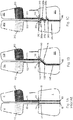
- a prior art microfluidic application e.g. Burger 2009
- the flows arrive at inlets 32 and 33 from microfluidic channels 22 and 23, respectively, and the flow is fractionated into flows (streams of small droplets 42 and 43 shown), respectively.
- the size of these droplets is dictated by the strength of the centrifugal field, the capillary forces at the inlet and the geometry of the inlet.
- the droplets As the droplets are released at two different points (i.e. inlets 32 and 33 ) they will be accelerated in the radial direction (i.e. in the direction of the centrifugal field) to land at two different points 52 and 53, respectively.
- reservoirs 102 and 103 provide two liquids 112 and 113 that flow through microfluidic channels 122 and 123 under the influence of a centrifugal field to emerge as individual flows 142 and 143 (shown as droplets) into mixing chamber 101 at inlets 132 and 133.
- a single straight, rectangular deflection element 105 is placed in the trajectory of both flows 142 and 143, which deflects the two flows to form a joint flow 145 (schematically illustrated), forcing both flows to land at a same nominal point 155 in mixing chamber 101.
- straight line trajectories from inlets 132 and 133 as in Fig.
- the flows impact on the deflection element after a short drop (although no drop here is required), and runs along the deflector to a common detachment point 165.
- the joint flow leaves the deflection element at the detachment point 165 to follow a radial trajectory, as there is no obstruction to the trajectory between the detachment point and a point on the mixing surface 155.
- the liquids instead of tending to develop separate pools, will stack upon each other forming thin lamellae with very small volume (practically the volume of a single droplet, or a microscopic amount of the fluid that is separated in passage as a joint flow, or at impact) but with very large interfacial surface area provided by the lamellae in the stacking direction. Since the surface to volume ratio is increased enormously, diffusive mixing is expected to occur quickly, and in some cases, practically instantaneously.
- the shapes and aspect ratios of the reservoirs, channels, and mixing chamber are substantially irrelevant to the present invention, as long as the centrifugal field allows for the desired fluid motion.
- the volume of the mixing chamber as a function of height of the mixed fluid is one feature that can impact the quality of mixing, as it affects the distance between the detachment point and the mixing surface.
- reservoirs 202 and 203 provide two liquids 212 and 213 that flow through microfluidic channels 222 and 223 under the influence of a centrifugal field to emerge as individual flows 242 and 243 into mixing chamber 201 at inlets 232 and 233.
- a four-wing deflection element 205a-d comprising four straight rectangular pieces is placed in the trajectories of both flows 242 and 243, which will deflect the flows to form a joint flow 245 and force the joint flow to land at a common point 255 in mixing chamber 201.
- the flows impact on the deflection elements and the joint flow leaves the deflection element at the same point 265 to follow a radial trajectory. Since the flows arrive at the same point 255, the liquids, instead of tending to develop separate pools, stack upon each other forming thin lamellae with very small volume (practically the volume of a single droplet, or microscopic amount) but with very large interfacial surface areas provided by the multitude of lamellae in the stacking direction. Since the surface to volume ratio is increased enormously, diffusive mixing occurs more quickly, and in some applications may be practically instantaneous.
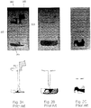
- Fig. 2 shows experimental results for the prior art arrangement without deflection element (e.g. Burger 2009) while Fig. 3 shows experimental results for the present invention using a four-wing deflection element.
- microfluidic devices were formed of hot embossed PDMS (having patterns to define the microfluidic features) on a flat Zeonor substrate.
- the mixing chamber had a volume of 40 ⁇ L, each reservoir had a volume of 20 ⁇ L, and the microfluidic channels and openings between the reservoirs and mixing chamber had a hydraulic diameter of about 500 ⁇ m.
- Two differently colored liquids were placed in reservoirs that were connected through straight radial channels to the mixing chamber, as shown in Fig. 1a .
- the liquids were both deionized distilled water with commercially available food-color.
- the microfluidic device was mounted to a home-built centrifuge, and operated at a rate of 700+/-10 rpm.
- Fig. 2A depicts configuration of liquids when flow has just started
- Fig. 2B depicts configuration of liquids at the end of the flow
- Fig. 2C depicts configuration of liquids 5 minutes after the end of the flow.
- Schematic diagrams beneath each experiment are manually drawn traces that more clearly show the boundaries between the liquids.
- the two liquids accumulate in different regions of the chamber thus reducing their mutual interface and reducing related diffusive mixing.
- the liquids are still significantly separated from each other and remain separated to a large extent even after 5 min ( Fig. 2C ). Black-shaded regions in the schematic diagrams represent regions in which mixing has occurred.
- the liquids are substantially mixed when viewed with small volumes of partially unmixed fluids at both opposite sides, which is consistent with deposition as successive layers. At the end of the flow they are highly mixed ( Fig. 3B and Fig. 3C ). Black-shaded regions in the schematic diagrams represent regions in which mixing has occurred. By discretizing, deforming, and interlacing the flows, the necessary diffusion lengths and related diffusion times are reduced drastically ( t ⁇ l 2 ).
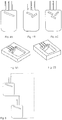
- the invention can be readily generalized for more than two fluids (e.g. 3, 4, 5 or more fluids) by using either a single-wing deflection element ( Fig. 4A ) or multiple-wing deflection elements ( Fig. 4B and Fig. 4C ) in the mixing chamber.
- the geometry of the deflection element may be varied (e.g. straight or curved) and combinations of curved and straight deflection elements may be employed.
- Fig. 4B shows a two-wing deflection element and
- Fig. 4C shows a three-wing deflection element.
- three channels for fluid flow are shown entering the mixing chamber.
- devices can be fabricated either by embossing or injection molding a plastic material or by CNC machining of practically any compatible material.
- the microfluidic channels and the mixing chamber can be carved either at the same level Fig. 5A ) or at different depths (Fig. 58) by embossing (machining, injection molding) the chamber deeper than the channels.
- the mixing chamber may serve as an incubator, or provide for thermal, chemical or radiological treatment, and may have conduits for cleaning or preparing the chamber before or after mixing.
- Fig. 6 schematically illustrates another embodiment of the present invention that permits multistage mixing.
- a mixing chamber of the form shown in Fig. 1B is provided with an exit channel.
- the exit channel leads to a second mixing chamber shown to be identical to the first. This arrangement allows for mixing of first and second fluid flows, output at the exit channel, with a third fluid flow, in the second mixing chamber.
- Fig. 6 does not require a third fluid flow. In some embodiments it may be preferred to repeat the discretization, deformation, and stacking of the output, to further improve mixing. If the second mixing chamber is only for this purpose, the deflector in the second chamber may be removed.
Landscapes
- Chemical & Material Sciences (AREA)
- Chemical Kinetics & Catalysis (AREA)
- Dispersion Chemistry (AREA)
- Engineering & Computer Science (AREA)
- Computer Hardware Design (AREA)
- Microelectronics & Electronic Packaging (AREA)
- Physical Or Chemical Processes And Apparatus (AREA)
Claims (14)
- Eine zentrifugale mikrofluidische Vorrichtung, umfassend eine mikrofluidische Mischkammer (101; 102) mit mindestens zwei Einlässen (132, 133; 232, 233) in entsprechende mikrofluidische Kanäle (122, 123; 222, 223) mit hydraulischen Durchmessern von weniger als 1 mm zum Durchlassen von Fluidströmen (142, 143; 242, 243) von jedem Kanal (122, 123; 222, 223) in die Kammer (101; 201) unter Einfluss eines Zentrifugalfelds, wobei die Einlässe (132, 133) beabstandet angeordnet sind, sodass geradlinige Trajektorien des Fluids eine Vermischungsfläche in der Kammer (101; 201) nicht an einer im Wesentlichen gleichen Stelle (155; 255) auf der Oberfläche kreuzen, dadurch gekennzeichnet,
dass die Kammer (101; 201) mindestens ein in den Trajektorien angeordnetes Ablenkelement (105; 205a-d) aufweist, wobei das mindestens eine Ablenkelement (105; 205a-d) so ausgerichtet ist, dass es den Strom ablenkt, sodass die abgelenkten Ströme die Vermischungsfläche an einer im Wesentlichen gleichen Stelle (155; 255) auf der Oberfläche berühren, wobei die Strecke einer Trajektorie von dem Ablenkelement (105; 205a-d) zu der Vermischungsfläche mindestens 1 mm beträgt, sodass mikroskopische Mengen der Fluidströme (142, 143; 242, 243) auf die Oberfläche, bzw. auf das zuvor aufgetragene Fluid, aufprallen und sich ausbreiten, um einen Stapel aus sich abwechselnden, dünnen Schichten der entsprechenden Fluide zu bilden und so eine große Diffusionsfläche zu schaffen. - Vorrichtung nach Anspruch 1, wobei das Ablenkelement (105; 205a-d) ein festes Merkmal umfasst, welches in die Mischkammer (101; 201) eingebaut ist.
- Vorrichtung nach Anspruch 2, wobei das feste Merkmal einen einzelnen Flügel umfasst.
- Vorrichtung nach Anspruch 2, wobei das feste Merkmal mehrere Flügel umfasst.
- Vorrichtung nach einem der Ansprüche 1 bis 4, wobei die Einlässe (132, 133; 232, 233) beabstandet angeordnet sind und der Abstand mindestens dem Durchmesser der Kanäle (122, 123; 222, 223) entspricht.
- Vorrichtung nach einem der Ansprüche 1 bis 5, wobei die im Wesentlichen gleiche Stelle (155; 255) eine Trennung von nicht mehr als dem Durchmesser der mikrofluidischen Kanäle (122, 123; 222, 223) umfasst.
- Vorrichtung nach einem der Ansprüche 1 bis 6, wobei das Ablenkelement (105; 205a-d) eine gerade Geometrie, eine gekrümmte Geometrie oder eine Kombination aus geraden und gekrümmten Geometrien aufweist.
- Vorrichtung nach einem der Ansprüche 1 bis 7, wobei die mikrofluidischen Kanäle (122, 123; 222, 223) jeweils mit einem entsprechenden Reservoir (102, 103; 202, 203) verbunden sind, wobei das Volumen eines jeden Reservoirs weniger als 1 ml beträgt.
- Vorrichtung nach Anspruch 8, wobei das Reservoir (102, 103; 202, 203) Folgendes enthält: eine Flüssigkeit, eine Flüssigkeit, die eine Zelle enthält, eine Flüssigkeit, die einen Virus enthält, eine Flüssigkeit, die eine Bakterie enthält, eine Flüssigkeit, die Partikel enthält, eine Flüssigkeit, die oberflächenaktivierte Partikel enthält oder eine Flüssigkeit, die magnetische Partikel enthält.
- Vorrichtung nach einem der Ansprüche 1 bis 9, wobei die Kammer (101; 201) einen Auslass hat, der eine auf die Trajektorien projektierte Position mindestens 1 mm unterhalb des Ablenkelements (105; 205a-d) einnimmt.
- Vorrichtung nach Anspruch 10, wobei der Auslass über einen dritten mikrofluidischen Kanal mit einem hydraulischen Durchmesser von weniger als 1 mm in Fluidverbindung mit einer sekundären Mischkammer steht, wobei die sekundäre Mischkammer eine hindernisfreie Trajektorie bietet, die eine Strecke von mindestens 1 mm vor Kontakt mit einer Vermischungsfläche aufweist.
- Vorrichtung nach Anspruch 11, wobei die sekundäre Mischkammer einen zweiten Einlass und entsprechend ein oder mehrere Ablenkelemente zum Vermischen des Fluids aus der mikrofluidischen Mischkammer mit einem anderen Fluid aufweist.
- Verfahren für das Vermischen von mindestens zwei Fluidströmen in einer zentrifugalen mikrofluidischen Vorrichtung, welches Folgendes umfasst:a. Bereitstellung von mindestens zwei mikrofluidischen Einlässen in eine Mischkammer (101; 102) der Vorrichtung mit hydraulischen Durchmessern von weniger als 1 mm, undb. Erzeugen eines Fluidstroms (142, 143; 242, 243) durch jeden Einlass (132, 133; 232, 233) unter Einfluss eines Zentrifugalfelds, wobei die Einlässe (132, 133; 232, 233) beabstandet in der Kammer (101; 201) angeordnet sind, sodass geradlinige Trajektorien der Ströme (142, 143; 242, 243) eine Vermischungsfläche in der Kammer (101; 201) an im Wesentlichen unterschiedlichen Stellen an der Oberfläche kreuzen;gekennzeichnet durchc. Ablenkung der Fluidströme (142, 143; 242, 243) durch ein Ablenkelement (105; 205a-d), bevor die Ströme (142, 143; 242, 243) die Vermischungsfläche berühren, sodass die Ströme (142, 143; 242, 243) die Vermischungsfläche an der im Wesentlichen gleichen Stelle (155; 255) berühren; undd. Bereitstellung einer hindernisfreien Trajektorie zwischen dem Ablenkelement (105; 205a-d) und der Vermischungsfläche mit einer Strecke von mindestens 1 mm, sodass mikroskopische Mengen der Fluidströme (142, 143; 242, 243) auf die Oberfläche bzw. auf das zuvor aufgetragene Fluid aufprallen und sich ausbreiten, um einen Stapel aus sich abwechselnden, dünnen Schichten der entsprechenden Fluide zu bilden und so eine große Diffusionsfläche zu schaffen.
- Verfahren nach Anspruch 13, wobei die Ablenkung erfolgt, indem ein festes Ablenkelement in der Mischkammer (101; 102) in die Trajektorien des Einlasses eingebaut wird, wobei dieses Ablenkelement eine in einem zum Zentrifugalfeld schiefen Winkel angebrachte Ablenkfläche aufweist.
Applications Claiming Priority (2)
| Application Number | Priority Date | Filing Date | Title |
|---|---|---|---|
| US201261599647P | 2012-02-16 | 2012-02-16 | |
| PCT/CA2013/000139 WO2013120190A1 (en) | 2012-02-16 | 2013-02-18 | Centrifugal microfluidic mixing apparatus and method |
Publications (3)
| Publication Number | Publication Date |
|---|---|
| EP2814773A1 EP2814773A1 (de) | 2014-12-24 |
| EP2814773A4 EP2814773A4 (de) | 2015-10-28 |
| EP2814773B1 true EP2814773B1 (de) | 2017-05-31 |
Family
ID=48983493
Family Applications (1)
| Application Number | Title | Priority Date | Filing Date |
|---|---|---|---|
| EP13749704.6A Active EP2814773B1 (de) | 2012-02-16 | 2013-02-18 | Zentrifugale mikrofluidische mischvorrichtung und verfahren |
Country Status (6)
| Country | Link |
|---|---|
| US (1) | US9555382B2 (de) |
| EP (1) | EP2814773B1 (de) |
| AU (1) | AU2013220890B2 (de) |
| CA (1) | CA2864641C (de) |
| ES (1) | ES2635549T3 (de) |
| WO (1) | WO2013120190A1 (de) |
Families Citing this family (9)
| Publication number | Priority date | Publication date | Assignee | Title |
|---|---|---|---|---|
| EP1894617B1 (de) * | 2006-08-31 | 2013-08-14 | Samsung Electronics Co., Ltd. | Verfahren zum Mischen von mindestens zwei Fluidarten in einem Zentrifugal-Mikrofluidbehandlungssubstrat |
| CA2864641C (en) * | 2012-02-16 | 2021-05-04 | National Research Council Of Canada | Centrifugal microfluidic mixing apparatus and method |
| DE102012202775B4 (de) * | 2012-02-23 | 2016-08-25 | Hahn-Schickard-Gesellschaft für angewandte Forschung e.V. | Fluidikmodul, vorrichtung und verfahren zum pumpen einer flüssigkeit |
| AU2015225844B2 (en) | 2014-03-07 | 2019-10-24 | National Research Council Of Canada | Centrifugal microfluidic chip control |
| EP3148702B1 (de) | 2014-05-26 | 2020-01-01 | National Research Council of Canada | Schwenkhalterung für zentrifugalen mikrofluidischen chip |
| DE102014224664B3 (de) * | 2014-12-02 | 2015-10-08 | Hahn-Schickard-Gesellschaft für angewandte Forschung e.V. | Vorrichtung und verfahren zur tropfenerzeugung |
| JP2022538389A (ja) * | 2019-06-28 | 2022-09-02 | ナショナル リサーチ カウンシル オブ カナダ | 遠心マイクロ流体チップ、キットおよびオンチップガス供給システム |
| US11938480B2 (en) | 2020-05-14 | 2024-03-26 | The Board Of Trustees Of The University Of Illinois Urbana, Illinois | Microfluidic diagnostic device with a three-dimensional (3D) flow architecture |
| WO2023018845A1 (en) * | 2021-08-12 | 2023-02-16 | Academia Sinica | Microfluidic mixer for enhanced three-dimensional mixing |
Family Cites Families (27)
| Publication number | Priority date | Publication date | Assignee | Title |
|---|---|---|---|---|
| US3795451A (en) * | 1973-04-24 | 1974-03-05 | Atomic Energy Commission | Rotor for fast analyzer of rotary cuvette type |
| US3829223A (en) * | 1973-07-20 | 1974-08-13 | Atomic Energy Commission | Mixing rotor for fast analyzer of rotary cuvette type with means for enhancing the mixing of sample and reagent liquids |
| FR2409514A1 (fr) * | 1977-11-17 | 1979-06-15 | Bretaudiere Jean Pierre | Perfectionnement aux appareils d'analyse par centrifugation |
| DE3044385A1 (de) * | 1980-11-25 | 1982-06-24 | Boehringer Mannheim Gmbh, 6800 Mannheim | Verfahren zur durchfuehrung analytischer bestimmungen und hierfuer geeignetes rotoreinsatzelement |
| DE3633343A1 (de) | 1986-09-10 | 1988-03-17 | Bayer Ag | Verfahren und vorrichtung zum herstellen eines kunststoff, insbesondere schaumstoff bildenden, fliessfaehigen reaktionsgemisches aus mindestens zwei fliessfaehigen reaktionskomponenten im durchlauf |
| DE19604289C2 (de) | 1996-02-07 | 1998-04-23 | Danfoss As | Mikromischer |
| US5826981A (en) | 1996-08-26 | 1998-10-27 | Nova Biomedical Corporation | Apparatus for mixing laminar and turbulent flow streams |
| JP4485731B2 (ja) | 2000-03-02 | 2010-06-23 | ダウ グローバル テクノロジーズ インコーポレイティド | 管状反応器、管状反応器中で液/液多相反応を行うための方法及び管状反応器中で芳香族化合物を環ニトロ化するための方法 |
| US6994749B2 (en) | 2001-06-08 | 2006-02-07 | Syrrx, Inc. | Microfluidic device for parallel delivery and mixing of fluids |
| AU2003224817B2 (en) * | 2002-04-01 | 2008-11-06 | Fluidigm Corporation | Microfluidic particle-analysis systems |
| EP2359689B1 (de) | 2002-09-27 | 2015-08-26 | The General Hospital Corporation | Mikrofluid-Vorrichtung zur Zelltrennung, sowie Verwendung derselben |
| US6916113B2 (en) * | 2003-05-16 | 2005-07-12 | Agilent Technologies, Inc. | Devices and methods for fluid mixing |
| US7347617B2 (en) | 2003-08-19 | 2008-03-25 | Siemens Healthcare Diagnostics Inc. | Mixing in microfluidic devices |
| EP1874920A4 (de) * | 2005-04-05 | 2009-11-04 | Cellpoint Diagnostics | Vorrichtungen und verfahren zur anreicherung und veränderung zirkulierender tumorzellen und anderer partikel |
| US7314060B2 (en) | 2005-04-23 | 2008-01-01 | Industrial Technology Research Institute | Fluid flow conducting module |
| US7316245B2 (en) | 2005-12-23 | 2008-01-08 | Bioquiddity, Inc. | Fluid flow control device |
| EP2530167A1 (de) | 2006-05-11 | 2012-12-05 | Raindance Technologies, Inc. | Mikrofluidische Vorrichtungen |
| EP1894617B1 (de) * | 2006-08-31 | 2013-08-14 | Samsung Electronics Co., Ltd. | Verfahren zum Mischen von mindestens zwei Fluidarten in einem Zentrifugal-Mikrofluidbehandlungssubstrat |
| US20090087925A1 (en) * | 2007-10-01 | 2009-04-02 | Zyomyx, Inc. | Devices and methods for analysis of samples with depletion of analyte content |
| US8622606B2 (en) | 2007-09-25 | 2014-01-07 | State Of Oregon Acting By And Through The State Board Of Higher Education On Behalf Of Oregon State University | Micro-channels, micro-mixers, and micro-reactors |
| US7830592B1 (en) | 2007-11-30 | 2010-11-09 | Sipix Imaging, Inc. | Display devices having micro-reflectors |
| EP2172260A1 (de) * | 2008-09-29 | 2010-04-07 | Corning Incorporated | Mehrflussweg-Mikroflüssigkeitsvorrichtungen |
| SG181855A1 (en) * | 2009-12-23 | 2012-07-30 | Agency Science Tech & Res | Microfluidic mixing apparatus and method |
| US8511889B2 (en) * | 2010-02-08 | 2013-08-20 | Agilent Technologies, Inc. | Flow distribution mixer |
| US8720036B2 (en) | 2010-03-09 | 2014-05-13 | Netbio, Inc. | Unitary biochip providing sample-in to results-out processing and methods of manufacture |
| AU2012278872A1 (en) * | 2011-07-04 | 2014-02-06 | National Research Council Of Canada | Centrifugal microfluidic platform |
| CA2864641C (en) * | 2012-02-16 | 2021-05-04 | National Research Council Of Canada | Centrifugal microfluidic mixing apparatus and method |
-
2013
- 2013-02-18 CA CA2864641A patent/CA2864641C/en active Active
- 2013-02-18 EP EP13749704.6A patent/EP2814773B1/de active Active
- 2013-02-18 ES ES13749704.6T patent/ES2635549T3/es active Active
- 2013-02-18 AU AU2013220890A patent/AU2013220890B2/en not_active Ceased
- 2013-02-18 WO PCT/CA2013/000139 patent/WO2013120190A1/en not_active Ceased
- 2013-02-18 US US13/261,941 patent/US9555382B2/en active Active
Also Published As
| Publication number | Publication date |
|---|---|
| CA2864641A1 (en) | 2013-08-22 |
| AU2013220890A1 (en) | 2014-10-02 |
| ES2635549T3 (es) | 2017-10-04 |
| CA2864641C (en) | 2021-05-04 |
| WO2013120190A1 (en) | 2013-08-22 |
| US20150138912A1 (en) | 2015-05-21 |
| AU2013220890B2 (en) | 2016-03-10 |
| EP2814773A4 (de) | 2015-10-28 |
| US9555382B2 (en) | 2017-01-31 |
| EP2814773A1 (de) | 2014-12-24 |
Similar Documents
| Publication | Publication Date | Title |
|---|---|---|
| EP2814773B1 (de) | Zentrifugale mikrofluidische mischvorrichtung und verfahren | |
| Xia et al. | Chaotic micromixers using two-layer crossing channels to exhibit fast mixing at low Reynolds numbers | |
| Schwesinger et al. | A modular microfluid system with an integrated micromixer | |
| Sudarsan et al. | Fluid mixing in planar spiral microchannels | |
| CN107583551A (zh) | 一种阶梯形通道加工字形挡板的平面被动式微混合器 | |
| Melin et al. | A fast passive and planar liquid sample micromixer | |
| US20150125947A1 (en) | Microfluidic device | |
| CN102151504A (zh) | 非对称分离重组扇形空腔结构微混合器 | |
| CN104525286B (zh) | 基于t型通道实现液滴同步融合的微流控芯片 | |
| TWI230683B (en) | The micromixer with overlapping-crisscross entrance | |
| US20210370303A1 (en) | Pressure insensitive microfluidic circuit for droplet generation and uses thereof | |
| EP1463579A1 (de) | Lochmikromischer | |
| KR102324465B1 (ko) | 미세 유체 혼합기 및 이를 이용한 유체 혼합방법 | |
| CN202199279U (zh) | 一种基于成涡结构强化混合的平面被动式微混合器 | |
| CN201959734U (zh) | 非对称分离重组扇形空腔结构微混合器 | |
| KR20190043725A (ko) | 3차원 유로구조 미세 유체 혼합기 | |
| KR101432729B1 (ko) | 원반형의 혼합부와 교차되는 혼합채널을 가진 미세혼합기 | |
| CN115245847A (zh) | 一种基于特斯拉阀的微混合芯片 | |
| KR20150105856A (ko) | 테일러 괴틀러 와류를 이용한 마이크로 믹서 및 그 제작방법 | |
| CN105289385A (zh) | 基于增强弯道二次流效应的扭曲弧形微混合器 | |
| CN105214546B (zh) | 一种基于脉动流的震荡射流式微混合器 | |
| CN102233241A (zh) | 一种基于成涡结构强化混合的平面被动式微混合器 | |
| CN106215789A (zh) | 一种基于射流原理的回流被动式微混合器 | |
| CN113842824A (zh) | 一种基于复合侧壁微结构增强混合效率的被动式微混合器 | |
| EP1930070A1 (de) | Mikrovorrichtung und verfahren zum zusammenführen von fluiden |
Legal Events
| Date | Code | Title | Description |
|---|---|---|---|
| PUAI | Public reference made under article 153(3) epc to a published international application that has entered the european phase |
Free format text: ORIGINAL CODE: 0009012 |
|
| 17P | Request for examination filed |
Effective date: 20140915 |
|
| AK | Designated contracting states |
Kind code of ref document: A1 Designated state(s): AL AT BE BG CH CY CZ DE DK EE ES FI FR GB GR HR HU IE IS IT LI LT LU LV MC MK MT NL NO PL PT RO RS SE SI SK SM TR |
|
| AX | Request for extension of the european patent |
Extension state: BA ME |
|
| DAX | Request for extension of the european patent (deleted) | ||
| RA4 | Supplementary search report drawn up and despatched (corrected) |
Effective date: 20150925 |
|
| RIC1 | Information provided on ipc code assigned before grant |
Ipc: B81B 7/00 20060101AFI20150921BHEP Ipc: B01F 13/00 20060101ALI20150921BHEP |
|
| GRAP | Despatch of communication of intention to grant a patent |
Free format text: ORIGINAL CODE: EPIDOSNIGR1 |
|
| INTG | Intention to grant announced |
Effective date: 20161215 |
|
| GRAS | Grant fee paid |
Free format text: ORIGINAL CODE: EPIDOSNIGR3 |
|
| GRAA | (expected) grant |
Free format text: ORIGINAL CODE: 0009210 |
|
| AK | Designated contracting states |
Kind code of ref document: B1 Designated state(s): AL AT BE BG CH CY CZ DE DK EE ES FI FR GB GR HR HU IE IS IT LI LT LU LV MC MK MT NL NO PL PT RO RS SE SI SK SM TR |
|
| REG | Reference to a national code |
Ref country code: CH Ref legal event code: EP Ref country code: GB Ref legal event code: FG4D |
|
| REG | Reference to a national code |
Ref country code: AT Ref legal event code: REF Ref document number: 897269 Country of ref document: AT Kind code of ref document: T Effective date: 20170615 |
|
| REG | Reference to a national code |
Ref country code: IE Ref legal event code: FG4D |
|
| REG | Reference to a national code |
Ref country code: DE Ref legal event code: R096 Ref document number: 602013021716 Country of ref document: DE |
|
| REG | Reference to a national code |
Ref country code: ES Ref legal event code: FG2A Ref document number: 2635549 Country of ref document: ES Kind code of ref document: T3 Effective date: 20171004 Ref country code: NL Ref legal event code: MP Effective date: 20170531 |
|
| REG | Reference to a national code |
Ref country code: LT Ref legal event code: MG4D |
|
| REG | Reference to a national code |
Ref country code: AT Ref legal event code: MK05 Ref document number: 897269 Country of ref document: AT Kind code of ref document: T Effective date: 20170531 |
|
| PG25 | Lapsed in a contracting state [announced via postgrant information from national office to epo] |
Ref country code: LT Free format text: LAPSE BECAUSE OF FAILURE TO SUBMIT A TRANSLATION OF THE DESCRIPTION OR TO PAY THE FEE WITHIN THE PRESCRIBED TIME-LIMIT Effective date: 20170531 Ref country code: GR Free format text: LAPSE BECAUSE OF FAILURE TO SUBMIT A TRANSLATION OF THE DESCRIPTION OR TO PAY THE FEE WITHIN THE PRESCRIBED TIME-LIMIT Effective date: 20170901 Ref country code: HR Free format text: LAPSE BECAUSE OF FAILURE TO SUBMIT A TRANSLATION OF THE DESCRIPTION OR TO PAY THE FEE WITHIN THE PRESCRIBED TIME-LIMIT Effective date: 20170531 Ref country code: AT Free format text: LAPSE BECAUSE OF FAILURE TO SUBMIT A TRANSLATION OF THE DESCRIPTION OR TO PAY THE FEE WITHIN THE PRESCRIBED TIME-LIMIT Effective date: 20170531 Ref country code: FI Free format text: LAPSE BECAUSE OF FAILURE TO SUBMIT A TRANSLATION OF THE DESCRIPTION OR TO PAY THE FEE WITHIN THE PRESCRIBED TIME-LIMIT Effective date: 20170531 Ref country code: NO Free format text: LAPSE BECAUSE OF FAILURE TO SUBMIT A TRANSLATION OF THE DESCRIPTION OR TO PAY THE FEE WITHIN THE PRESCRIBED TIME-LIMIT Effective date: 20170831 |
|
| PG25 | Lapsed in a contracting state [announced via postgrant information from national office to epo] |
Ref country code: RS Free format text: LAPSE BECAUSE OF FAILURE TO SUBMIT A TRANSLATION OF THE DESCRIPTION OR TO PAY THE FEE WITHIN THE PRESCRIBED TIME-LIMIT Effective date: 20170531 Ref country code: SE Free format text: LAPSE BECAUSE OF FAILURE TO SUBMIT A TRANSLATION OF THE DESCRIPTION OR TO PAY THE FEE WITHIN THE PRESCRIBED TIME-LIMIT Effective date: 20170531 Ref country code: IS Free format text: LAPSE BECAUSE OF FAILURE TO SUBMIT A TRANSLATION OF THE DESCRIPTION OR TO PAY THE FEE WITHIN THE PRESCRIBED TIME-LIMIT Effective date: 20170930 Ref country code: LV Free format text: LAPSE BECAUSE OF FAILURE TO SUBMIT A TRANSLATION OF THE DESCRIPTION OR TO PAY THE FEE WITHIN THE PRESCRIBED TIME-LIMIT Effective date: 20170531 Ref country code: BG Free format text: LAPSE BECAUSE OF FAILURE TO SUBMIT A TRANSLATION OF THE DESCRIPTION OR TO PAY THE FEE WITHIN THE PRESCRIBED TIME-LIMIT Effective date: 20170831 Ref country code: NL Free format text: LAPSE BECAUSE OF FAILURE TO SUBMIT A TRANSLATION OF THE DESCRIPTION OR TO PAY THE FEE WITHIN THE PRESCRIBED TIME-LIMIT Effective date: 20170531 |
|
| PG25 | Lapsed in a contracting state [announced via postgrant information from national office to epo] |
Ref country code: SK Free format text: LAPSE BECAUSE OF FAILURE TO SUBMIT A TRANSLATION OF THE DESCRIPTION OR TO PAY THE FEE WITHIN THE PRESCRIBED TIME-LIMIT Effective date: 20170531 Ref country code: CZ Free format text: LAPSE BECAUSE OF FAILURE TO SUBMIT A TRANSLATION OF THE DESCRIPTION OR TO PAY THE FEE WITHIN THE PRESCRIBED TIME-LIMIT Effective date: 20170531 Ref country code: DK Free format text: LAPSE BECAUSE OF FAILURE TO SUBMIT A TRANSLATION OF THE DESCRIPTION OR TO PAY THE FEE WITHIN THE PRESCRIBED TIME-LIMIT Effective date: 20170531 Ref country code: RO Free format text: LAPSE BECAUSE OF FAILURE TO SUBMIT A TRANSLATION OF THE DESCRIPTION OR TO PAY THE FEE WITHIN THE PRESCRIBED TIME-LIMIT Effective date: 20170531 Ref country code: EE Free format text: LAPSE BECAUSE OF FAILURE TO SUBMIT A TRANSLATION OF THE DESCRIPTION OR TO PAY THE FEE WITHIN THE PRESCRIBED TIME-LIMIT Effective date: 20170531 |
|
| REG | Reference to a national code |
Ref country code: FR Ref legal event code: PLFP Year of fee payment: 6 |
|
| PG25 | Lapsed in a contracting state [announced via postgrant information from national office to epo] |
Ref country code: SM Free format text: LAPSE BECAUSE OF FAILURE TO SUBMIT A TRANSLATION OF THE DESCRIPTION OR TO PAY THE FEE WITHIN THE PRESCRIBED TIME-LIMIT Effective date: 20170531 Ref country code: PL Free format text: LAPSE BECAUSE OF FAILURE TO SUBMIT A TRANSLATION OF THE DESCRIPTION OR TO PAY THE FEE WITHIN THE PRESCRIBED TIME-LIMIT Effective date: 20170531 |
|
| REG | Reference to a national code |
Ref country code: DE Ref legal event code: R097 Ref document number: 602013021716 Country of ref document: DE |
|
| PLBE | No opposition filed within time limit |
Free format text: ORIGINAL CODE: 0009261 |
|
| STAA | Information on the status of an ep patent application or granted ep patent |
Free format text: STATUS: NO OPPOSITION FILED WITHIN TIME LIMIT |
|
| 26N | No opposition filed |
Effective date: 20180301 |
|
| PG25 | Lapsed in a contracting state [announced via postgrant information from national office to epo] |
Ref country code: SI Free format text: LAPSE BECAUSE OF FAILURE TO SUBMIT A TRANSLATION OF THE DESCRIPTION OR TO PAY THE FEE WITHIN THE PRESCRIBED TIME-LIMIT Effective date: 20170531 |
|
| REG | Reference to a national code |
Ref country code: CH Ref legal event code: PL |
|
| PG25 | Lapsed in a contracting state [announced via postgrant information from national office to epo] |
Ref country code: MC Free format text: LAPSE BECAUSE OF FAILURE TO SUBMIT A TRANSLATION OF THE DESCRIPTION OR TO PAY THE FEE WITHIN THE PRESCRIBED TIME-LIMIT Effective date: 20170531 |
|
| REG | Reference to a national code |
Ref country code: IE Ref legal event code: MM4A |
|
| REG | Reference to a national code |
Ref country code: BE Ref legal event code: MM Effective date: 20180228 |
|
| PG25 | Lapsed in a contracting state [announced via postgrant information from national office to epo] |
Ref country code: CH Free format text: LAPSE BECAUSE OF NON-PAYMENT OF DUE FEES Effective date: 20180228 Ref country code: LI Free format text: LAPSE BECAUSE OF NON-PAYMENT OF DUE FEES Effective date: 20180228 Ref country code: LU Free format text: LAPSE BECAUSE OF NON-PAYMENT OF DUE FEES Effective date: 20180218 |
|
| PG25 | Lapsed in a contracting state [announced via postgrant information from national office to epo] |
Ref country code: IE Free format text: LAPSE BECAUSE OF NON-PAYMENT OF DUE FEES Effective date: 20180218 |
|
| PG25 | Lapsed in a contracting state [announced via postgrant information from national office to epo] |
Ref country code: BE Free format text: LAPSE BECAUSE OF NON-PAYMENT OF DUE FEES Effective date: 20180228 |
|
| PG25 | Lapsed in a contracting state [announced via postgrant information from national office to epo] |
Ref country code: MT Free format text: LAPSE BECAUSE OF NON-PAYMENT OF DUE FEES Effective date: 20180218 |
|
| PG25 | Lapsed in a contracting state [announced via postgrant information from national office to epo] |
Ref country code: TR Free format text: LAPSE BECAUSE OF FAILURE TO SUBMIT A TRANSLATION OF THE DESCRIPTION OR TO PAY THE FEE WITHIN THE PRESCRIBED TIME-LIMIT Effective date: 20170531 |
|
| PG25 | Lapsed in a contracting state [announced via postgrant information from national office to epo] |
Ref country code: PT Free format text: LAPSE BECAUSE OF FAILURE TO SUBMIT A TRANSLATION OF THE DESCRIPTION OR TO PAY THE FEE WITHIN THE PRESCRIBED TIME-LIMIT Effective date: 20170531 Ref country code: HU Free format text: LAPSE BECAUSE OF FAILURE TO SUBMIT A TRANSLATION OF THE DESCRIPTION OR TO PAY THE FEE WITHIN THE PRESCRIBED TIME-LIMIT; INVALID AB INITIO Effective date: 20130218 |
|
| PG25 | Lapsed in a contracting state [announced via postgrant information from national office to epo] |
Ref country code: MK Free format text: LAPSE BECAUSE OF NON-PAYMENT OF DUE FEES Effective date: 20170531 Ref country code: CY Free format text: LAPSE BECAUSE OF FAILURE TO SUBMIT A TRANSLATION OF THE DESCRIPTION OR TO PAY THE FEE WITHIN THE PRESCRIBED TIME-LIMIT Effective date: 20170531 |
|
| PG25 | Lapsed in a contracting state [announced via postgrant information from national office to epo] |
Ref country code: AL Free format text: LAPSE BECAUSE OF FAILURE TO SUBMIT A TRANSLATION OF THE DESCRIPTION OR TO PAY THE FEE WITHIN THE PRESCRIBED TIME-LIMIT Effective date: 20170531 |
|
| PGFP | Annual fee paid to national office [announced via postgrant information from national office to epo] |
Ref country code: ES Payment date: 20240305 Year of fee payment: 12 |
|
| PGFP | Annual fee paid to national office [announced via postgrant information from national office to epo] |
Ref country code: GB Payment date: 20240118 Year of fee payment: 12 |
|
| PGFP | Annual fee paid to national office [announced via postgrant information from national office to epo] |
Ref country code: IT Payment date: 20240126 Year of fee payment: 12 Ref country code: FR Payment date: 20240123 Year of fee payment: 12 |
|
| PGFP | Annual fee paid to national office [announced via postgrant information from national office to epo] |
Ref country code: DE Payment date: 20250226 Year of fee payment: 13 |
|
| GBPC | Gb: european patent ceased through non-payment of renewal fee |
Effective date: 20250218 |
|
| PG25 | Lapsed in a contracting state [announced via postgrant information from national office to epo] |
Ref country code: GB Free format text: LAPSE BECAUSE OF NON-PAYMENT OF DUE FEES Effective date: 20250218 |
|
| PG25 | Lapsed in a contracting state [announced via postgrant information from national office to epo] |
Ref country code: IT Free format text: LAPSE BECAUSE OF NON-PAYMENT OF DUE FEES Effective date: 20250218 Ref country code: FR Free format text: LAPSE BECAUSE OF NON-PAYMENT OF DUE FEES Effective date: 20250228 |
|
| REG | Reference to a national code |
Ref country code: ES Ref legal event code: FD2A Effective date: 20260401 |
|
| PG25 | Lapsed in a contracting state [announced via postgrant information from national office to epo] |
Ref country code: ES Free format text: LAPSE BECAUSE OF NON-PAYMENT OF DUE FEES Effective date: 20250219 |