EP2814996B1 - Buse et tête de buse - Google Patents
Buse et tête de buse Download PDFInfo
- Publication number
- EP2814996B1 EP2814996B1 EP13749430.8A EP13749430A EP2814996B1 EP 2814996 B1 EP2814996 B1 EP 2814996B1 EP 13749430 A EP13749430 A EP 13749430A EP 2814996 B1 EP2814996 B1 EP 2814996B1
- Authority
- EP
- European Patent Office
- Prior art keywords
- precursor
- channel
- discharge
- precursor supply
- channels
- Prior art date
- Legal status (The legal status is an assumption and is not a legal conclusion. Google has not performed a legal analysis and makes no representation as to the accuracy of the status listed.)
- Active
Links
Images




Classifications
-
- C—CHEMISTRY; METALLURGY
- C23—COATING METALLIC MATERIAL; COATING MATERIAL WITH METALLIC MATERIAL; CHEMICAL SURFACE TREATMENT; DIFFUSION TREATMENT OF METALLIC MATERIAL; COATING BY VACUUM EVAPORATION, BY SPUTTERING, BY ION IMPLANTATION OR BY CHEMICAL VAPOUR DEPOSITION, IN GENERAL; INHIBITING CORROSION OF METALLIC MATERIAL OR INCRUSTATION IN GENERAL
- C23C—COATING METALLIC MATERIAL; COATING MATERIAL WITH METALLIC MATERIAL; SURFACE TREATMENT OF METALLIC MATERIAL BY DIFFUSION INTO THE SURFACE, BY CHEMICAL CONVERSION OR SUBSTITUTION; COATING BY VACUUM EVAPORATION, BY SPUTTERING, BY ION IMPLANTATION OR BY CHEMICAL VAPOUR DEPOSITION, IN GENERAL
- C23C16/00—Chemical coating by decomposition of gaseous compounds, without leaving reaction products of surface material in the coating, i.e. chemical vapour deposition [CVD] processes
- C23C16/44—Chemical coating by decomposition of gaseous compounds, without leaving reaction products of surface material in the coating, i.e. chemical vapour deposition [CVD] processes characterised by the method of coating
- C23C16/455—Chemical coating by decomposition of gaseous compounds, without leaving reaction products of surface material in the coating, i.e. chemical vapour deposition [CVD] processes characterised by the method of coating characterised by the method used for introducing gases into reaction chamber or for modifying gas flows in reaction chamber
- C23C16/45563—Gas nozzles
- C23C16/45574—Nozzles for more than one gas
-
- B—PERFORMING OPERATIONS; TRANSPORTING
- B05—SPRAYING OR ATOMISING IN GENERAL; APPLYING FLUENT MATERIALS TO SURFACES, IN GENERAL
- B05B—SPRAYING APPARATUS; ATOMISING APPARATUS; NOZZLES
- B05B13/00—Machines or plants for applying liquids or other fluent materials to surfaces of objects or other work by spraying, not covered by groups B05B1/00 - B05B11/00
- B05B13/02—Means for supporting work; Arrangement or mounting of spray heads; Adaptation or arrangement of means for feeding work
- B05B13/0278—Arrangement or mounting of spray heads
-
- C—CHEMISTRY; METALLURGY
- C23—COATING METALLIC MATERIAL; COATING MATERIAL WITH METALLIC MATERIAL; CHEMICAL SURFACE TREATMENT; DIFFUSION TREATMENT OF METALLIC MATERIAL; COATING BY VACUUM EVAPORATION, BY SPUTTERING, BY ION IMPLANTATION OR BY CHEMICAL VAPOUR DEPOSITION, IN GENERAL; INHIBITING CORROSION OF METALLIC MATERIAL OR INCRUSTATION IN GENERAL
- C23C—COATING METALLIC MATERIAL; COATING MATERIAL WITH METALLIC MATERIAL; SURFACE TREATMENT OF METALLIC MATERIAL BY DIFFUSION INTO THE SURFACE, BY CHEMICAL CONVERSION OR SUBSTITUTION; COATING BY VACUUM EVAPORATION, BY SPUTTERING, BY ION IMPLANTATION OR BY CHEMICAL VAPOUR DEPOSITION, IN GENERAL
- C23C16/00—Chemical coating by decomposition of gaseous compounds, without leaving reaction products of surface material in the coating, i.e. chemical vapour deposition [CVD] processes
- C23C16/44—Chemical coating by decomposition of gaseous compounds, without leaving reaction products of surface material in the coating, i.e. chemical vapour deposition [CVD] processes characterised by the method of coating
- C23C16/4412—Details relating to the exhausts, e.g. pumps, filters, scrubbers, particle traps
-
- C—CHEMISTRY; METALLURGY
- C23—COATING METALLIC MATERIAL; COATING MATERIAL WITH METALLIC MATERIAL; CHEMICAL SURFACE TREATMENT; DIFFUSION TREATMENT OF METALLIC MATERIAL; COATING BY VACUUM EVAPORATION, BY SPUTTERING, BY ION IMPLANTATION OR BY CHEMICAL VAPOUR DEPOSITION, IN GENERAL; INHIBITING CORROSION OF METALLIC MATERIAL OR INCRUSTATION IN GENERAL
- C23C—COATING METALLIC MATERIAL; COATING MATERIAL WITH METALLIC MATERIAL; SURFACE TREATMENT OF METALLIC MATERIAL BY DIFFUSION INTO THE SURFACE, BY CHEMICAL CONVERSION OR SUBSTITUTION; COATING BY VACUUM EVAPORATION, BY SPUTTERING, BY ION IMPLANTATION OR BY CHEMICAL VAPOUR DEPOSITION, IN GENERAL
- C23C16/00—Chemical coating by decomposition of gaseous compounds, without leaving reaction products of surface material in the coating, i.e. chemical vapour deposition [CVD] processes
- C23C16/44—Chemical coating by decomposition of gaseous compounds, without leaving reaction products of surface material in the coating, i.e. chemical vapour deposition [CVD] processes characterised by the method of coating
- C23C16/455—Chemical coating by decomposition of gaseous compounds, without leaving reaction products of surface material in the coating, i.e. chemical vapour deposition [CVD] processes characterised by the method of coating characterised by the method used for introducing gases into reaction chamber or for modifying gas flows in reaction chamber
- C23C16/45523—Pulsed gas flow or change of composition over time
- C23C16/45525—Atomic layer deposition [ALD]
- C23C16/45544—Atomic layer deposition [ALD] characterized by the apparatus
-
- C—CHEMISTRY; METALLURGY
- C23—COATING METALLIC MATERIAL; COATING MATERIAL WITH METALLIC MATERIAL; CHEMICAL SURFACE TREATMENT; DIFFUSION TREATMENT OF METALLIC MATERIAL; COATING BY VACUUM EVAPORATION, BY SPUTTERING, BY ION IMPLANTATION OR BY CHEMICAL VAPOUR DEPOSITION, IN GENERAL; INHIBITING CORROSION OF METALLIC MATERIAL OR INCRUSTATION IN GENERAL
- C23C—COATING METALLIC MATERIAL; COATING MATERIAL WITH METALLIC MATERIAL; SURFACE TREATMENT OF METALLIC MATERIAL BY DIFFUSION INTO THE SURFACE, BY CHEMICAL CONVERSION OR SUBSTITUTION; COATING BY VACUUM EVAPORATION, BY SPUTTERING, BY ION IMPLANTATION OR BY CHEMICAL VAPOUR DEPOSITION, IN GENERAL
- C23C16/00—Chemical coating by decomposition of gaseous compounds, without leaving reaction products of surface material in the coating, i.e. chemical vapour deposition [CVD] processes
- C23C16/44—Chemical coating by decomposition of gaseous compounds, without leaving reaction products of surface material in the coating, i.e. chemical vapour deposition [CVD] processes characterised by the method of coating
- C23C16/455—Chemical coating by decomposition of gaseous compounds, without leaving reaction products of surface material in the coating, i.e. chemical vapour deposition [CVD] processes characterised by the method of coating characterised by the method used for introducing gases into reaction chamber or for modifying gas flows in reaction chamber
- C23C16/45523—Pulsed gas flow or change of composition over time
- C23C16/45525—Atomic layer deposition [ALD]
- C23C16/45544—Atomic layer deposition [ALD] characterized by the apparatus
- C23C16/45548—Atomic layer deposition [ALD] characterized by the apparatus having arrangements for gas injection at different locations of the reactor for each ALD half-reaction
-
- C—CHEMISTRY; METALLURGY
- C23—COATING METALLIC MATERIAL; COATING MATERIAL WITH METALLIC MATERIAL; CHEMICAL SURFACE TREATMENT; DIFFUSION TREATMENT OF METALLIC MATERIAL; COATING BY VACUUM EVAPORATION, BY SPUTTERING, BY ION IMPLANTATION OR BY CHEMICAL VAPOUR DEPOSITION, IN GENERAL; INHIBITING CORROSION OF METALLIC MATERIAL OR INCRUSTATION IN GENERAL
- C23C—COATING METALLIC MATERIAL; COATING MATERIAL WITH METALLIC MATERIAL; SURFACE TREATMENT OF METALLIC MATERIAL BY DIFFUSION INTO THE SURFACE, BY CHEMICAL CONVERSION OR SUBSTITUTION; COATING BY VACUUM EVAPORATION, BY SPUTTERING, BY ION IMPLANTATION OR BY CHEMICAL VAPOUR DEPOSITION, IN GENERAL
- C23C16/00—Chemical coating by decomposition of gaseous compounds, without leaving reaction products of surface material in the coating, i.e. chemical vapour deposition [CVD] processes
- C23C16/44—Chemical coating by decomposition of gaseous compounds, without leaving reaction products of surface material in the coating, i.e. chemical vapour deposition [CVD] processes characterised by the method of coating
- C23C16/455—Chemical coating by decomposition of gaseous compounds, without leaving reaction products of surface material in the coating, i.e. chemical vapour deposition [CVD] processes characterised by the method of coating characterised by the method used for introducing gases into reaction chamber or for modifying gas flows in reaction chamber
- C23C16/45563—Gas nozzles
- C23C16/45578—Elongated nozzles, tubes with holes
-
- H—ELECTRICITY
- H01—ELECTRIC ELEMENTS
- H01J—ELECTRIC DISCHARGE TUBES OR DISCHARGE LAMPS
- H01J37/00—Discharge tubes with provision for introducing objects or material to be exposed to the discharge, e.g. for the purpose of examination or processing thereof
- H01J37/32—Gas-filled discharge tubes
Definitions
- the present invention relates to a nozzle for subjecting a surface of a substrate to a gaseous precursor and particularly to a nozzle head according to the preamble of claim 1.
- the present invention further relates to a nozzle head for subjecting a surface of a substrate to successive surface reactions of at least a first precursor and a second precursor, and particularly to a nozzle head according to the preamble of claim 7.
- nozzle heads and nozzles are used for subjecting a surface of a substrate to successive surface reactions of at least a first precursor and a second precursor according to the principles of atomic layer deposition method (ALD).
- ALD atomic layer deposition method
- typically two gaseous precursors are introduced into the ALD reactor in separate stages.
- the gaseous precursors effectively react with the substrate surface, resulting in deposition of a growth layer.
- the precursor stages are typically followed or separated by an inert-gas purge stage that eliminates the excess precursor from the surface of the substrate prior to the separate introduction of the other precursor. Therefore an ALD process requires alternating in sequence the flux of precursors to the surface of the substrate. This repeated sequence of alternating surface reactions and purge stages between is a typical ALD deposition cycle.
- the prior art apparatuses for continuously operating ALD usually comprise a nozzle head having precursor nozzles arranged successively adjacent to each other such that the surface of the substrate may be subjected successively to surface reaction of at least a first and second precursors.
- the nozzles provide one or more first precursor supply channels for supplying the first precursor and one or more second precursor supply channels for supplying the second precursor.
- a nozzle head is usually also provided with one or more purge gas channels and one or more discharge channels for discharging both precursors and purge gas.
- the channels are arranged in the following order: at least a first precursor nozzle, a first discharge channel, purge gas channel, a discharge channel, a second precursor nozzle, a discharge channel, a purge gas channel and a discharge channel, optionally repeated a plurality of times.
- the problem with this prior art nozzle head is that it comprises several different nozzles and channels which makes the nozzle head complicated and rather large.
- the nozzles and the nozzle head are moved in relation to the substrate such that the nozzles and nozzle head scan over the surface of the substrate subjecting the substrate surface successively to the different precursors.
- the prior art nozzles and nozzle heads do not provide compact and effective constructions for industrial scale apparatuses.
- Publication US 2009/0304924 discloses an apparatus and method for large area high speed atomic layer chemical vapor processing and publication US 2010/037820 discloses a vapor deposition reactor.
- the object of the present invention is to provide a nozzle and a nozzle head such that the above mentioned prior art problems are solved or at least alleviated.
- the objects of the present invention are achieved with a nozzle according to the independent claim 1, in which a precursor supply element is arranged to extend inside a discharge channel such that the precursor supply element divides the discharge channel in the longitudinal direction to a first discharge sub-channel and a second discharge sub-channel on opposite sides of the precursor supply element for supplying precursor through the discharge channel.
- first and second precursor supply channels is arranged to supply precursor through a discharge channel for dividing the discharge channel in the longitudinal direction to a first discharge sub-channel and a second discharge sub-channel on opposite sides of the precursor supply channel.
- the invention is based on the idea of supplying the gaseous precursor material through a discharge channel such that a discharge sub-channel is formed on opposite sides of the precursor supply.
- the present invention provides a nozzle comprising an output face via which the precursor is supplied, a precursor supply element for supplying precursor and a longitudinal discharge channel open to and along the output face for discharging at least a fraction of the precursor supplied from the precursor channel.
- the precursor supply element is arranged to extend inside the discharge channel such that the precursor supply element divides the discharge channel in the longitudinal direction to a first discharge sub-channel and a second discharge sub-channel on opposite sides of the precursor supply element for supplying precursor through the discharge channel.
- the present invention provides a nozzle in which the precursor supply channel is arranged inside a discharge channel and the precursor is supplied through the discharge channel.
- This nozzle arrangement may further be used in a nozzle head having an output face and comprising one or more first longitudinal precursor supply channels for subjecting the surface of the substrate to the first precursor via the output face, one or more second longitudinal precursor supply channels for subjecting the surface of the substrate to the second precursor via the output face, and one or more longitudinal discharge channels open to the output face for discharging at least a fraction of the first and second precursor supplied from the first and second precursor supply channels.
- At least one of the first and second precursor supply channels is arranged to supply precursor through a discharge channel for dividing the discharge channel in the longitudinal direction to a first discharge sub-channel and a second discharge sub-channel on opposite sides of the precursor supply channel. Therefore at least one of the first and second precursor supply channels may be arranged inside a discharge channel for dividing the discharge channel in the longitudinal direction to a first discharge sub-channel and a second discharge sub-channel on opposite sides of the precursor supply channel.
- An advantage of the nozzle and nozzle head of the present invention is a compact structure in which the discharge channel and the precursor supply channel are nested. This eliminates the need for separate discharge channels and precursor supply channels. Furthermore, a single discharge channel is arranged to form a discharge sub-channel on both sides of the precursor supply channel instead of two separate discharge channels. Therefore, the nozzle and nozzle head is simpler in structure and more compact. This means that a larger number of precursor supply channels may be formed on a certain surface area of the output face of the nozzle head and further growth layers may be produces on the substrate surface with one scan.
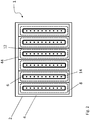
- Figure 1 shows schematically one embodiment of a nozzle head 1 according to the present.
- the nozzle head 1 comprises nozzle head body 2 and a nozzle head output face 4 via which the gaseous precursors are supplied.
- the nozzle head output face 4 is planar, but in an alternative embodiment it may also be non-planar, curved, cylindrical or have any other suitable form.
- the nozzle head 1 is provided with nozzles 8 arranged adjacently to each other and extending longitudinally along the output face 4.
- the nozzles 8 are shown with dashed lines in figures 1 and 2 .
- the nozzles 8 are separated with a distance or gap 12 from each other.
- the nozzles 8 comprise a discharge channel 6 and a precursor supply channel 10 arranged inside the discharge channel 6.
- the discharge channel 6 and the precursor supply channel 10 are formed as longitudinal channels. As shown in figure 1 the precursor supply channel 10 divides the discharge channel 6 into two discharge sub-channels in the longitudinal direction, one on each side of the precursor supply channel 10 for discharging at least a fraction of the supplied precursor. In a preferred embodiment the discharge channel 6 and the precursor supply channel 10 flush with the nozzle head output face 4. Alternatively the discharge channel 6 and/or the precursor supply channel may protrude from the nozzle head output face 4 or may be partly below the nozzle head output face 4. It should be noted that the nozzles 8 may be integral parts of the nozzle head 1 and the nozzle head body 2 or alternatively they may be detachable parts which may be removed or replaced.
- the gap 12 between the nozzles 8 is in this embodiment provided with a purge gas channel 44 for supplying purge gas, such as nitrogen.
- the purge gas channels are preferably longer than the nozzles 8 or the precursor supply channels.
- the purge gas channel 44 is provided for separating the adjacent nozzles 8 and the precursors from each other and for purging the surface of the substrate.
- the nozzle head output face 4 is further provided with discharge perimeter 5, which surrounds the nozzles 8 and the purge gas channels 44.
- the discharge perimeter 5 is connected to vacuum pump or the like such that it may discharge precursors and purge gas from the nozzle head output face 4.
- the discharge perimeter 5 is continuous, but alternative it may be formed from two or more separate discharge channels parts arranged to surround the nozzles 8 and the purge gas channels 44.
- a purge gas perimeter (not shown) may also be arranged to the nozzle in the same way as the discharge perimeter 5.
- the purge gas perimeter is preferably provided on inner side of the discharge perimeter 5 on the nozzle head output face 4.
- Figure 2 shows an alternative embodiment in which the precursor supply channel comprises several supply holes 14 extending and opening towards the nozzle head output face 4.
- the precursor supply channel 10 is furthermore arranged in the middle of the discharge channel 6 such that the discharge channel 6 surrounds the precursor supply channel 10 from all directions on the nozzle head output face 4.
- the ends of the discharge channels 6 on the opposite sides of the precursor supply channel 6 are connected to form a discharge channel surrounding the precursor supply channel 10.
- the precursor supply channel divides the discharge channel 6 into two discharge sub-channels in the longitudinal direction, one on each side of the precursor supply channel.
- the ends of the discharge sub-channels connect to each other forming a circumferential discharge channel around the precursor supply channel on the nozzle head output face 4.
- the gap 12 between the nozzles 8 may be provided with a purge gas channel for supplying purge gas, such as nitrogen for purging the substrate surface.
- the purge channels 44 are connected to each other such that the purge gas channels 44 surround separately each nozzle 8 and also all the nozzles 8 on the nozzle head output face 4. It should be noted that the purge gas channels 44 also be arranged to surround only each nozzle 8 separately or only all the nozzles 8.
- the purge gas channels 44 When the purge gas channels 44 are arranged to surround the nozzles 8 the surrounding discharge perimeter 5, shown in figure 1 , may be omitted. However, the discharge perimeter 5 may also be provided on the nozzle head output face 4 surrounding the connected purge gas channels 44.
- Figure 3 shows one embodiment the nozzle 8 according to the present invention.
- the nozzle 8 comprises a nozzle body 20 and a precursor supply element 30 for supplying precursor on the surface of a substrate 100.
- the nozzle 8 is shown disassembled such that the precursor supply element 30 is out of the nozzle body 20.
- the precursor supply element 30 and the nozzle body 20 are separate parts, but in alternative embodiment they may also be integral parts. Therefore, the precursor supply element 30 may be integral part of the body 20 or a separate part.
- the nozzle body 20 comprises a nozzle output face 24 via which the precursor is supplied.
- the nozzle body 20 further comprises a longitudinal discharge channel 6 open to and along the nozzle output face 24.
- the discharge channel 6 has side walls 27 extending the longitudinal direction of the discharge channel 6.
- the nozzle body 20 further comprises a discharge conduit 22 extending substantially parallel and in fluid connection with the discharge channel 6 for exhausting discharged material from the discharge channel 6. Accordingly the nozzle body 20 is arranged to form the discharge channel 6 and discharge conduit 22 having longitudinal walls 29. The width of the discharge conduit 22 is greater than the width of the discharge channel 22 for enhancing the discharge pressure.
- the discharge conduit 22 and the discharge channel 6 are connected to a suction device (not shown) for providing suction. In a preferred embodiment the suction may be arranged to one or both longitudinal ends or the discharge conduit 22 and/or discharge channel 6.
- the precursor supply element 30 is arranged to be installed at least partly inside the nozzle body 20.
- the precursor supply element 30 comprises one or more longitudinal precursor supply channels 10 open to the nozzle output face 24 for supplying precursor via the output face 24.
- the precursor supply element 30 further comprises a precursor conduit 32 in fluid connection with the precursor supply channel 10 for conducting precursor to the precursor supply channel 10.
- the precursor supply channel 10 is formed as a longitudinal channel open to and along the output face 24 and extending a as channel from the precursor conduit 32 to the end face 34 of the precursor supply channel 10.
- the longitudinal precursor supply channel 10 comprises an expansion 38 in the vicinity of the output face 24 and the end face 34 for increasing the width of the longitudinal precursor channel 10 at the output face 24. The expansion spreads and uniforms the precursor supply to the substrate surface.
- the expansion 38 equalizes the precursor supply in the width direction of the precursor supply channel 10 and decelerates the supply rate of the precursors.
- the expansion 38 provides a pressure balancing structure when the nozzle 8 or the nozzle head 1 is arranged close to a substrate surface.
- the precursor supply element may comprise one or more one or more precursor supply holes 14 extending from the precursor conduit 32 and opening to the output face 24 for forming the precursor supply channel. These kinds of supply holes 14 may extend in a transversal direction in relation to the longitudinal direction of the discharge channel 6.
- the precursor supply holes 14 may form the supply channel or channels.
- the precursor supply holes 14 extend between the precursor conduit 32 and the longitudinal precursor supply channel 10 open to and along the output face 24.
- the longitudinal expansion 38 may form the precursor supply channel 10 and the supply holes extend between the expansion 38 and the precursor conduit 32.
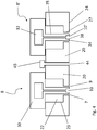
- Figure 4 shows two nozzles 8, 8' of figure 3 are installed adjacently and assembled such that precursor supply element 30 is inside the nozzle body 20.
- the first nozzle 8 is arranged to supply a first precursor via the first precursor supply channel 10 and the second precursor 8' is arranged to supply second precursor via the second precursor supply channel 10'.
- a purge gas element for supplying purge gas.
- the purge gas element comprises a purge gas conduit 40 and a purge gas supply channel 44 open to the nozzle output face 24.
- a nozzle head of figures 1 and 2 may be formed by arranging two or more nozzles 10, 10' adjacently.
- the precursor supply element 30 is arranged to extend through the discharge channel 6 to the output face 24.
- the precursor supply element 30 is arranged to extend longitudinally inside the discharge channel 6 such that the precursor supply element 30 divides the discharge channel 6 in the longitudinal direction to a first discharge sub-channel 7 and a second discharge sub-channel 9 on opposite sides of the precursor supply element 30 for supplying precursor through the discharge channel 6.
- the precursor supply element 30 is also arranged to extend through the discharge conduit 22 and the discharge channel 6 to the output face 24 such that the precursor channel 10 divides the discharge conduit 22 to two discharge sub-conduits on opposite sides of the precursor supply element 30.
- the precursor supply element 30 may be arranged to provide a fluid connection between the discharge sub-conduits of the discharge conduit 22. Alternatively there is no fluid connection between the discharge sub-conduits.
- the precursor supply element 30 is preferably arranged to extend inside the discharge channel 6 such that the end face 34 of the supply element 30 is substantially flush with the output face 24.
- the discharge sub-channels 7, 9 are thus formed between the outer wall 35 of the precursor supply channel 10 and the inner walls 27 of the discharge channel 6.
- the nozzle 8, 8' of figure 4 enables one discharge channel 6 to be used for providing two discharge channels 7, 9 on opposite sides of the precursor supply channel 10, 10'. This also enables to use one suction device or suction connection for these both discharge sub-channels 7, 9.
- the precursors may be supplied to the precursor conduits 32 from the longitudinal ends of the precursor conduits 32. Furthermore, the present invention enables different precursors to be supplied from different ends to the longitudinal precursor conduits 32.
- Figure 5 shows an alternative embodiment in which the purge gas channels 45 is formed to the nozzle body 20.
- the nozzle body 20 therefore comprises a purge gas conduit 41 and a purge gas supply channel open to the nozzle output face 24 and extending longitudinally substantially in the direction of the discharge channel 6.
- This purge gas arrangement provides an integral purge gas supply to the nozzle 8.
- Figure 6 shows an alternative embodiment in which a nozzle head is formed by arranging nozzles adjacent to each other.
- the nozzle body 20 comprises a purge gas channel 47 extending open to the nozzle output face 24 and extending longitudinally substantially in the direction of the discharge channel 6.
- one purge gas channel 47 is provided between two discharge channels 6 and between the discharge sub-channels 7 and 9.
- the nozzle head has a compact structure the nozzle body 20 or the nozzle head body 2 has only two different channels on the output face 4, 24, the purge gas channel 45, 47 and the discharge channel 6 as the precursor supply channel 10 is formed inside the discharge channel 6.
- Figure 7 shows a nozzle head in which the nozzle head body 2 comprises discharge conduits 22 in fluid connection to the discharge channels 6.
- the longitudinal discharge channels 6, discharge conduits 22 and the precursor supply channels 10 are formed as integral parts or machined shapes to the nozzle head body 2.
- the discharge channels and the discharge conduits 22 are separated from each other with partitioning walls 21. It should be noted as there is no precursor conduit in the embodiment of figure 7 , also the discharge conduit 22 may be omitted or the discharge channel 6 may have uniform width also in the height direction.
- Figure 8 shows an alternative embodiment of the nozzle in which the precursor supply element 50 extends inside the discharge conduit 22 or discharge channel but not through the discharge conduit 22 in the height or width direction.
- the precursor supply element 50 may provide a fluid connection between the first and second discharge sub-channels 7, 9.
- the precursor supply element 50 extends substantially in a nested fashion inside the discharge conduit 22 or the discharge channel 6, at least in the lateral direction of the discharge channel 6.
- the precursor supply element 50 may also extend substantially coaxially inside the discharge conduit 22 or the discharge channel 6, at least in the lateral direction of the discharge channel 6.
- the precursor supply element 50 comprises a precursor conduit 52 and a precursor supply channel 10 opening on and along the nozzle output face 24 such that it divides the discharge channel 6 into two discharge sub-channels 7, 9.
- the precursor supply element 50 is arranged to extend inside the discharge channel 6 such that the end face 34 the supply element 50 is substantially flush with the nozzle output face 24.
- Figure 9 shows an alternative embodiment in which both the precursor supply channel 10 and the discharge channels 7, 9 are arranged to extend longitudinally inside the purge gas element 55 such that they divide the purge gas channel in the longitudinal direction to a first purge sub-channel 53 and a second purge gas sub-channel 54 on opposite sides of the precursor supply element 50 and the discharge channels 7, 9.
- the purge gas element also comprises a purge gas conduit 56 for supplying purge gas to the purge gas sub-channels 53, 54.
- the precursor supply element 50 and the nozzle body 20 forming the discharge channels 7, 9 are nested inside the purge gas element 55 and purge gas conduit 56. Thus there is fluid connection between the purge gas sub-channels 53, 54 via the purge gas conduit 56.
- the discharge conduit 22 may extends substantially in a nested fashion inside purge gas element 55.
- the discharge conduit 22 may also extend substantially coaxially inside the purge gas conduit 56, at least in the lateral direction of the discharge channels 7, 9.
- the principle shown in figure 9 may also be applied to the nozzles and nozzle heads of figure 1 to 8 .
- the precursor supply channel and the discharge channel may be arranged inside the purge gas channel such that the precursor supply channel and the discharge channel divide the purge gas channel into first and second purge gas sub-channels 53, 54 on opposite side of the discharge channel and precursor supply channel. Therefore his principle may also be used in the nozzle structures shown in figures 3 to 8 .
- the present invention therefore provides a nozzle head in which nozzle 8, 8' described above may be used for subjecting a surface of a substrate to successive surface reactions of at least of first and second gaseous precursor for forming thin film on the surface of the substrate according to the principles of atomic layer deposition. 25.
- the nozzle described above may be used for subjecting a surface of a substrate to surface reaction a gaseous precursor.
- the nozzle head of the present invention for subjecting a surface of a substrate 100 to successive surface reactions of at least a first gaseous precursor and a second gaseous precursor may comprise one or more first longitudinal precursor supply channels 10 for subjecting the surface of the substrate 100 to the first precursor via the nozzle head output face 4, one or more second longitudinal precursor supply channels 10' for subjecting the surface of the substrate 100 to the second precursor via the output face 4, and one or more longitudinal discharge channels 6 open to the output face 4 for discharging at least a fraction of the first and second precursor supplied from the first and second precursor supply channels 10, 10'.
- At least one of the first and second precursor supply channels 10, 10' is arranged to supply precursor through a discharge channel 6 for dividing the discharge channel 6 in the longitudinal direction to a first discharge sub-channel 7 and a second discharge sub-channel 9 on opposite sides of the precursor supply channel 10, 10'.
- all the precursors are supplied through the discharge channels 6.
- the first and second supply channels 10, 10' may be each arranged to supply precursor through a discharge channel 6, or that the first and second supply channels 10, 10' may be each arranged inside a discharge channel 6.
- only one precursor channels is arranged according to the present invention.
- At least one of the first and second precursor supply channels 10, 10' of the nozzle head is arranged inside a discharge channel 6 for dividing the discharge channel 6 in the longitudinal direction to a first discharge sub-channel 7 and a second discharge sub-channel 9 on opposite sides of the precursor supply channel 10, 10'.
- the first and second precursor supply channels 10, 10' may be arranged to extend through the discharge channel 6 to the nozzle head output face 4 in a direction transversal to the longitudinal direction of the discharge channel 6.
- the first and second precursor supply channels 10, 10' are arranged to extend inside and along the discharge channel 6. They may also be arranged to extend substantially coaxially inside and along the discharge channel 6, at least in the width direction of the discharge channel 6.
Landscapes
- Chemical & Material Sciences (AREA)
- Engineering & Computer Science (AREA)
- General Chemical & Material Sciences (AREA)
- Chemical Kinetics & Catalysis (AREA)
- Materials Engineering (AREA)
- Mechanical Engineering (AREA)
- Metallurgy (AREA)
- Organic Chemistry (AREA)
- Physics & Mathematics (AREA)
- Plasma & Fusion (AREA)
- Analytical Chemistry (AREA)
- Chemical Vapour Deposition (AREA)
Claims (14)
- Buse (8) agencée de façon à soumettre une surface d'un substrat (100) à un précurseur gazeux, la buse (8) comprenant :- une face de sortie (24) par l'intermédiaire de laquelle est fourni le
précurseur;- un élément d'alimentation de précurseur (30, 50) pour fournir le
précurseur;- un canal d'évacuation longitudinal (6) ouvert vers et le long de la face de sortie (24) pour évacuer au moins une fraction du précurseur fourni à partir du canal de précurseur (10), et- au moins un canal de gaz de purge (45, 47) ouvert à la face de sortie (24), dans laquelle la buse (8) comprend en outre un corps (20) formant le canal d'évacuation (6), et le corps comprend en outre un conduit d'évacuation (22) s'étendant essentiellement de manière parallèle et en communication fluidique avec le canal d'évacuation (6) pour évacuer le précurseur évacué à partir du canal d'évacuation (6), l'élément d'alimentation de précurseur (30, 50) est agencé de façon à s'étendre de manière longitudinale à l'intérieur du canal d'évacuation (6) de telle sorte que l'élément d'alimentation de précurseur (30, 50) divise le canal d'évacuation (6) suivant la direction longitudinale en un premier sous-canal d'évacuation (7) et un second sous-canal d'évacuation (9) sur des côtés opposés de l'élément d'alimentation de précurseur (30, 50) pour fournir le précurseur à travers le canal d'évacuation (6), et l'élément d'alimentation de précurseur (30, 50) est agencé de façon à s'étendre à travers le conduit d'évacuation (22) de telle sorte que le canal de précurseur (10) divise le conduit d'évacuation (22) en deux sous-conduits d'évacuation sur des côtés opposés de l'élément d'alimentation de précurseur (30, 50). - Buse selon la revendication 1, caractérisée en ce que l'élément d'alimentation de précurseur (30, 50) fait partie intégrante du corps (20) ou est une partie séparée.
- Buse selon la revendication1 ou 2, caractérisée en ce que l'élément d'alimentation de précurseur (30, 50) comprend :- un ou plusieurs canaux d'alimentation de précurseur (10, 14) ouverts à la face de sortie (24) pour fournir le précurseur par l'intermédiaire de la face de sortie (24) ; et/ ou- un conduit de précurseur (32, 52) en connexion fluidique avec le canal d'alimentation de précurseur (10, 14) pour conduire le précurseur au canal d'alimentation de précurseur (10, 14) ; et/ ou- une extension (38) à proximité de la face de sortie (24) pour augmenter la largeur du canal de précurseur longitudinal (10) au niveau de la face de sortie (24) ; et/ ou- un ou plusieurs orifices d'alimentation de précurseur (14) s'étendant à partir du conduit de précurseur (32, 52) et s'ouvrant à la face de sortie (24) pour former le canal d'alimentation de précurseur ; et/ ou- un ou plusieurs orifices d'alimentation de précurseur (14) s'étendant à partir du conduit de précurseur (32, 52) et s'ouvrant à la face de sortie (24) pour former le canal d'alimentation de précurseur, les orifices d'alimentation de précurseur (14) formant les canaux d'alimentation, ou les orifices d'alimentation de précurseur (14) s'étendant entre le conduit de précurseur (32, 52) et le canal d'alimentation de précurseur longitudinal (10) ouvert à et le long de la face de sortie (24).
- Buse selon l'une quelconque des revendications 1 à 3, caractérisée en ce que :- l'élément d'alimentation de précurseur (30, 50) s'étend à travers le canal d'évacuation (6) à la face de sortie (24) ; ou- l'élément d'alimentation de précurseur (30) s'étend à travers le conduit d'évacuation (22) et le canal d'évacuation (6) à la face de sortie (24) de telle sorte que le canal de précurseur (10) divise le conduit d'évacuation (22) en deux sous-conduits d'évacuation sur des côtés opposés de l'élément d'alimentation de précurseur (30, 50).
- Buse selon l'une quelconque des revendications 1 à 4, caractérisée en ce que :- l'élément d'alimentation de précurseur (50) s'étend à l'intérieur du conduit d'évacuation (22) fournissant une connexion fluidique entre les premier et second sous-canaux d'évacuation (7, 9) ; et/ ou- l'élément d'alimentation de précurseur (30, 50) est agencé de façon à s'étendre à l'intérieur du canal d'évacuation (6) de telle sorte que la face d'extrémité (34) de l'élément d'alimentation (30, 50) est essentiellement au même niveau que la face de sortie (24).
- Buse selon la revendication 1, caractérisée en ce que l'élément d'alimentation de précurseur (10) et le canal d'évacuation (6) sont agencés à l'intérieur du canal de gaz de purge (45, 47) de telle sorte que le canal d'alimentation de précurseur (10) et le canal d'évacuation (6) divisent le canal de gaz de purge (44, 47) en des premier et second sous-canaux de gaz de purge (53, 54) sur des côtés opposés du canal d'évacuation (6) et du canal d'alimentation de précurseur (10).
- Tête de buse (1) pour soumettre une surface d'un substrat (100) à des réactions de surface successives d'au moins un premier précurseur gazeux et d'un second précurseur gazeux, la tête de buse (1) ayant une face de sortie (4) et comprenant :- un ou plusieurs premiers canaux d'alimentation de précurseur longitudinaux (10) pour soumettre la surface du substrat (100) au premier précurseur par l'intermédiaire de la face de sortie (4) ; et- un ou plusieurs seconds canaux d'alimentation de précurseur longitudinaux (10) pour soumettre la surface du substrat (100) au second précurseur par l'intermédiaire de la face de sortie (4), et- un ou plusieurs canaux d'évacuation longitudinaux (6) ouverts à la face de sortie (4) pour évacuer au moins une fraction des premier et second précurseurs fournis à partir des premier et second canaux d'alimentation (10, 10'), etun ou plusieurs canaux de gaz de purge (45, 47) pour fournir un gaz de purge à la surface du substrat (100),
caractérisée en ce que la tête de buse (1) comprend une ou plusieurs buses (8), dans laquelle une buse (8) comprend un corps de buse (20) et un élément d'alimentation de précurseur (30), le corps de buse (20) comprend un canal d'évacuation (6) et un conduit d'évacuation (22) s'étendant essentiellement de manière parallèle et en communication fluidique avec le canal d'évacuation (6) pour évacuer le précurseur évacué à partir du canal d'évacuation (6), et
l'élément d'alimentation de précurseur (30) comprend le ou les canaux d'alimentation de précurseur longitudinaux (10, 10'), et en ce que
au moins un des premier et second canaux d'alimentation de précurseur (10, 10') est agencé pour fournir un précurseur à travers le conduit d'évacuation (22) et le canal d'évacuation (6) et agencé pour diviser
le conduit d'évacuation (22) en deux sous-conduits d'évacuation sur des côtés opposés du canal d'alimentation de précurseur (10, 10') et
le canal d'évacuation (6) suivant la direction longitudinale vers un premier sous-canal d'évacuation (7) et un second sous-canal d'évacuation (9) sur des côtés opposés du canal d'alimentation de précurseur (10, 10'). - Tête de buse (1) selon la revendication 7, caractérisée en ce que :- au moins un des premier et second canaux d'alimentation de précurseur (10, 10') est agencé à l'intérieur d'un canal d'évacuation (6) pour diviser le canal d'évacuation (6) suivant la direction longitudinale en un premier sous-canal d'évacuation (7) et un second sous-canal d'évacuation (9) sur des côtés opposés du canal d'alimentation de précurseur (10, 10') ; et/ ou- les premier et second canaux d'alimentation (10, 10') sont chacun agencés de façon à fournir un précurseur à travers un canal d'évacuation (6), ou en ce que les premier et second canaux d'alimentation (10, 10') sont chacun agencés à l'intérieur d'un canal d'évacuation (6).
- Tête de buse selon la revendication 7 ou 8, caractérisée en ce que :- les premier et second canaux d'alimentation de précurseur (10, 10') sont agencés de façon à s'étendre à travers à travers le canal d'évacuation (6) jusqu'à la face de sortie (4) suivant une direction transversale à la direction longitudinale du canal d'évacuation (6) ; ou- les premier et second canaux d'alimentation de précurseur (10, 10') sont agencés de façon à s'étendre à l'intérieur et le long du canal d'évacuation (6) ; ou- les premier et second canaux d'alimentation de précurseur (10, 10') sont agencés pour s'étendre essentiellement de manière coaxiale à l'intérieur et le long du canal d'évacuation (6).
- Tête de buse selon l'une quelconque des revendications 7 à 9, caractérisée en ce que :- la tête de buse (1) comprend en outre un ou plusieurs canaux de gaz de purge (45, 47) disposés entre les canaux d'évacuation (6) pour fournir un gaz de purge à la surface du substrat (100).
- Tête de buse selon l'une quelconque des revendications 7 à 10, caractérisée en ce que la tête de buse (1) comprend en outre un périmètre d'évacuation (5) entourant les buses (8) sur la face de sortie (4).
- Tête de buse selon l'une quelconque des revendications 7 à 11, caractérisée en ce que la tête de buse comprend une ou plusieurs buses (8) selon les revendications 1 à 6 pour former un ou plusieurs canaux d'alimentation de précurseur (10, 10') et canaux d'évacuation (6).
- Utilisation d'une buse selon les revendications 1 à 6, pour soumettre une surface d'un substrat à une réaction de surface d'un précurseur gazeux.
- Utilisation d'une tête de buse selon les revendications 7 à 12 pour soumettre une surface d'un substrat à des réactions de surface successives d'au moins un premier précurseur gazeux et un second précurseur gazeux pour former un film mince sur la surface du substrat selon les principes d'une déposition par couche atomique.
Applications Claiming Priority (2)
| Application Number | Priority Date | Filing Date | Title |
|---|---|---|---|
| FI20125186A FI123320B (en) | 2012-02-17 | 2012-02-17 | Nozzle and nozzle head |
| PCT/FI2013/050154 WO2013121102A2 (fr) | 2012-02-17 | 2013-02-12 | Buse et tête de buse |
Publications (3)
| Publication Number | Publication Date |
|---|---|
| EP2814996A2 EP2814996A2 (fr) | 2014-12-24 |
| EP2814996A4 EP2814996A4 (fr) | 2015-03-11 |
| EP2814996B1 true EP2814996B1 (fr) | 2018-12-26 |
Family
ID=47843915
Family Applications (1)
| Application Number | Title | Priority Date | Filing Date |
|---|---|---|---|
| EP13749430.8A Active EP2814996B1 (fr) | 2012-02-17 | 2013-02-12 | Buse et tête de buse |
Country Status (6)
| Country | Link |
|---|---|
| US (1) | US20150004318A1 (fr) |
| EP (1) | EP2814996B1 (fr) |
| CN (1) | CN104114744B (fr) |
| EA (1) | EA029749B1 (fr) |
| FI (1) | FI123320B (fr) |
| WO (1) | WO2013121102A2 (fr) |
Families Citing this family (291)
| Publication number | Priority date | Publication date | Assignee | Title |
|---|---|---|---|---|
| US7976631B2 (en) * | 2007-10-16 | 2011-07-12 | Applied Materials, Inc. | Multi-gas straight channel showerhead |
| US20130023129A1 (en) | 2011-07-20 | 2013-01-24 | Asm America, Inc. | Pressure transmitter for a semiconductor processing environment |
| US10714315B2 (en) | 2012-10-12 | 2020-07-14 | Asm Ip Holdings B.V. | Semiconductor reaction chamber showerhead |
| US20160376700A1 (en) | 2013-02-01 | 2016-12-29 | Asm Ip Holding B.V. | System for treatment of deposition reactor |
| US11414759B2 (en) | 2013-11-29 | 2022-08-16 | Taiwan Semiconductor Manufacturing Co., Ltd | Mechanisms for supplying process gas into wafer process apparatus |
| TWI545224B (zh) * | 2014-02-26 | 2016-08-11 | 國立中央大學 | 用於有機金屬化學氣相沉積設備之進氣系統 |
| US11015245B2 (en) | 2014-03-19 | 2021-05-25 | Asm Ip Holding B.V. | Gas-phase reactor and system having exhaust plenum and components thereof |
| JP6320824B2 (ja) * | 2014-03-31 | 2018-05-09 | 株式会社東芝 | ガス供給管、およびガス処理装置 |
| FI126315B (en) * | 2014-07-07 | 2016-09-30 | Beneq Oy | A nozzle head, apparatus and method for subjecting a substrate surface to successive surface reactions |
| US10858737B2 (en) | 2014-07-28 | 2020-12-08 | Asm Ip Holding B.V. | Showerhead assembly and components thereof |
| US10941490B2 (en) | 2014-10-07 | 2021-03-09 | Asm Ip Holding B.V. | Multiple temperature range susceptor, assembly, reactor and system including the susceptor, and methods of using the same |
| FI126894B (en) * | 2014-12-22 | 2017-07-31 | Beneq Oy | Nozzle head, apparatus and method for coating a substrate surface |
| US10276355B2 (en) | 2015-03-12 | 2019-04-30 | Asm Ip Holding B.V. | Multi-zone reactor, system including the reactor, and method of using the same |
| US10458018B2 (en) | 2015-06-26 | 2019-10-29 | Asm Ip Holding B.V. | Structures including metal carbide material, devices including the structures, and methods of forming same |
| KR102420015B1 (ko) * | 2015-08-28 | 2022-07-12 | 삼성전자주식회사 | Cs-ald 장치의 샤워헤드 |
| US10211308B2 (en) | 2015-10-21 | 2019-02-19 | Asm Ip Holding B.V. | NbMC layers |
| EP3390687A4 (fr) * | 2015-12-17 | 2019-10-23 | Beneq OY | Buse de précurseur de revêtement et tête de buse |
| US11139308B2 (en) | 2015-12-29 | 2021-10-05 | Asm Ip Holding B.V. | Atomic layer deposition of III-V compounds to form V-NAND devices |
| US10529554B2 (en) | 2016-02-19 | 2020-01-07 | Asm Ip Holding B.V. | Method for forming silicon nitride film selectively on sidewalls or flat surfaces of trenches |
| US10343920B2 (en) | 2016-03-18 | 2019-07-09 | Asm Ip Holding B.V. | Aligned carbon nanotubes |
| US10367080B2 (en) | 2016-05-02 | 2019-07-30 | Asm Ip Holding B.V. | Method of forming a germanium oxynitride film |
| US11453943B2 (en) | 2016-05-25 | 2022-09-27 | Asm Ip Holding B.V. | Method for forming carbon-containing silicon/metal oxide or nitride film by ALD using silicon precursor and hydrocarbon precursor |
| US9859151B1 (en) | 2016-07-08 | 2018-01-02 | Asm Ip Holding B.V. | Selective film deposition method to form air gaps |
| US10612137B2 (en) | 2016-07-08 | 2020-04-07 | Asm Ip Holdings B.V. | Organic reactants for atomic layer deposition |
| KR102532607B1 (ko) | 2016-07-28 | 2023-05-15 | 에이에스엠 아이피 홀딩 비.브이. | 기판 가공 장치 및 그 동작 방법 |
| US9887082B1 (en) | 2016-07-28 | 2018-02-06 | Asm Ip Holding B.V. | Method and apparatus for filling a gap |
| US9812320B1 (en) | 2016-07-28 | 2017-11-07 | Asm Ip Holding B.V. | Method and apparatus for filling a gap |
| US11532757B2 (en) | 2016-10-27 | 2022-12-20 | Asm Ip Holding B.V. | Deposition of charge trapping layers |
| US10714350B2 (en) | 2016-11-01 | 2020-07-14 | ASM IP Holdings, B.V. | Methods for forming a transition metal niobium nitride film on a substrate by atomic layer deposition and related semiconductor device structures |
| KR102546317B1 (ko) | 2016-11-15 | 2023-06-21 | 에이에스엠 아이피 홀딩 비.브이. | 기체 공급 유닛 및 이를 포함하는 기판 처리 장치 |
| KR102762543B1 (ko) | 2016-12-14 | 2025-02-05 | 에이에스엠 아이피 홀딩 비.브이. | 기판 처리 장치 |
| US11581186B2 (en) | 2016-12-15 | 2023-02-14 | Asm Ip Holding B.V. | Sequential infiltration synthesis apparatus |
| US11447861B2 (en) | 2016-12-15 | 2022-09-20 | Asm Ip Holding B.V. | Sequential infiltration synthesis apparatus and a method of forming a patterned structure |
| US11251019B2 (en) * | 2016-12-15 | 2022-02-15 | Toyota Jidosha Kabushiki Kaisha | Plasma device |
| KR102700194B1 (ko) * | 2016-12-19 | 2024-08-28 | 에이에스엠 아이피 홀딩 비.브이. | 기판 처리 장치 |
| US10269558B2 (en) | 2016-12-22 | 2019-04-23 | Asm Ip Holding B.V. | Method of forming a structure on a substrate |
| US11390950B2 (en) | 2017-01-10 | 2022-07-19 | Asm Ip Holding B.V. | Reactor system and method to reduce residue buildup during a film deposition process |
| US10468261B2 (en) | 2017-02-15 | 2019-11-05 | Asm Ip Holding B.V. | Methods for forming a metallic film on a substrate by cyclical deposition and related semiconductor device structures |
| US10529563B2 (en) | 2017-03-29 | 2020-01-07 | Asm Ip Holdings B.V. | Method for forming doped metal oxide films on a substrate by cyclical deposition and related semiconductor device structures |
| US10770286B2 (en) | 2017-05-08 | 2020-09-08 | Asm Ip Holdings B.V. | Methods for selectively forming a silicon nitride film on a substrate and related semiconductor device structures |
| US12040200B2 (en) | 2017-06-20 | 2024-07-16 | Asm Ip Holding B.V. | Semiconductor processing apparatus and methods for calibrating a semiconductor processing apparatus |
| US11306395B2 (en) | 2017-06-28 | 2022-04-19 | Asm Ip Holding B.V. | Methods for depositing a transition metal nitride film on a substrate by atomic layer deposition and related deposition apparatus |
| KR20190009245A (ko) | 2017-07-18 | 2019-01-28 | 에이에스엠 아이피 홀딩 비.브이. | 반도체 소자 구조물 형성 방법 및 관련된 반도체 소자 구조물 |
| US11018002B2 (en) | 2017-07-19 | 2021-05-25 | Asm Ip Holding B.V. | Method for selectively depositing a Group IV semiconductor and related semiconductor device structures |
| US11374112B2 (en) | 2017-07-19 | 2022-06-28 | Asm Ip Holding B.V. | Method for depositing a group IV semiconductor and related semiconductor device structures |
| US10541333B2 (en) | 2017-07-19 | 2020-01-21 | Asm Ip Holding B.V. | Method for depositing a group IV semiconductor and related semiconductor device structures |
| US10590535B2 (en) | 2017-07-26 | 2020-03-17 | Asm Ip Holdings B.V. | Chemical treatment, deposition and/or infiltration apparatus and method for using the same |
| TWI815813B (zh) | 2017-08-04 | 2023-09-21 | 荷蘭商Asm智慧財產控股公司 | 用於分配反應腔內氣體的噴頭總成 |
| US10692741B2 (en) | 2017-08-08 | 2020-06-23 | Asm Ip Holdings B.V. | Radiation shield |
| US10770336B2 (en) | 2017-08-08 | 2020-09-08 | Asm Ip Holding B.V. | Substrate lift mechanism and reactor including same |
| US11139191B2 (en) | 2017-08-09 | 2021-10-05 | Asm Ip Holding B.V. | Storage apparatus for storing cassettes for substrates and processing apparatus equipped therewith |
| US11769682B2 (en) | 2017-08-09 | 2023-09-26 | Asm Ip Holding B.V. | Storage apparatus for storing cassettes for substrates and processing apparatus equipped therewith |
| US11830730B2 (en) | 2017-08-29 | 2023-11-28 | Asm Ip Holding B.V. | Layer forming method and apparatus |
| US11056344B2 (en) | 2017-08-30 | 2021-07-06 | Asm Ip Holding B.V. | Layer forming method |
| KR102491945B1 (ko) | 2017-08-30 | 2023-01-26 | 에이에스엠 아이피 홀딩 비.브이. | 기판 처리 장치 |
| US11295980B2 (en) | 2017-08-30 | 2022-04-05 | Asm Ip Holding B.V. | Methods for depositing a molybdenum metal film over a dielectric surface of a substrate by a cyclical deposition process and related semiconductor device structures |
| JP6863199B2 (ja) | 2017-09-25 | 2021-04-21 | トヨタ自動車株式会社 | プラズマ処理装置 |
| US10658205B2 (en) | 2017-09-28 | 2020-05-19 | Asm Ip Holdings B.V. | Chemical dispensing apparatus and methods for dispensing a chemical to a reaction chamber |
| US10403504B2 (en) | 2017-10-05 | 2019-09-03 | Asm Ip Holding B.V. | Method for selectively depositing a metallic film on a substrate |
| FI129730B (en) | 2017-10-18 | 2022-08-15 | Beneq Oy | Nozzle and nozzle head |
| US10923344B2 (en) | 2017-10-30 | 2021-02-16 | Asm Ip Holding B.V. | Methods for forming a semiconductor structure and related semiconductor structures |
| US11022879B2 (en) | 2017-11-24 | 2021-06-01 | Asm Ip Holding B.V. | Method of forming an enhanced unexposed photoresist layer |
| TWI791689B (zh) | 2017-11-27 | 2023-02-11 | 荷蘭商Asm智慧財產控股私人有限公司 | 包括潔淨迷你環境之裝置 |
| JP7214724B2 (ja) | 2017-11-27 | 2023-01-30 | エーエスエム アイピー ホールディング ビー.ブイ. | バッチ炉で利用されるウェハカセットを収納するための収納装置 |
| US10872771B2 (en) | 2018-01-16 | 2020-12-22 | Asm Ip Holding B. V. | Method for depositing a material film on a substrate within a reaction chamber by a cyclical deposition process and related device structures |
| KR102695659B1 (ko) | 2018-01-19 | 2024-08-14 | 에이에스엠 아이피 홀딩 비.브이. | 플라즈마 보조 증착에 의해 갭 충진 층을 증착하는 방법 |
| TWI799494B (zh) | 2018-01-19 | 2023-04-21 | 荷蘭商Asm 智慧財產控股公司 | 沈積方法 |
| US11081345B2 (en) | 2018-02-06 | 2021-08-03 | Asm Ip Holding B.V. | Method of post-deposition treatment for silicon oxide film |
| US11685991B2 (en) | 2018-02-14 | 2023-06-27 | Asm Ip Holding B.V. | Method for depositing a ruthenium-containing film on a substrate by a cyclical deposition process |
| US10896820B2 (en) | 2018-02-14 | 2021-01-19 | Asm Ip Holding B.V. | Method for depositing a ruthenium-containing film on a substrate by a cyclical deposition process |
| US10731249B2 (en) | 2018-02-15 | 2020-08-04 | Asm Ip Holding B.V. | Method of forming a transition metal containing film on a substrate by a cyclical deposition process, a method for supplying a transition metal halide compound to a reaction chamber, and related vapor deposition apparatus |
| KR102636427B1 (ko) | 2018-02-20 | 2024-02-13 | 에이에스엠 아이피 홀딩 비.브이. | 기판 처리 방법 및 장치 |
| US10975470B2 (en) | 2018-02-23 | 2021-04-13 | Asm Ip Holding B.V. | Apparatus for detecting or monitoring for a chemical precursor in a high temperature environment |
| US11473195B2 (en) | 2018-03-01 | 2022-10-18 | Asm Ip Holding B.V. | Semiconductor processing apparatus and a method for processing a substrate |
| US11629406B2 (en) | 2018-03-09 | 2023-04-18 | Asm Ip Holding B.V. | Semiconductor processing apparatus comprising one or more pyrometers for measuring a temperature of a substrate during transfer of the substrate |
| US11114283B2 (en) | 2018-03-16 | 2021-09-07 | Asm Ip Holding B.V. | Reactor, system including the reactor, and methods of manufacturing and using same |
| KR102646467B1 (ko) | 2018-03-27 | 2024-03-11 | 에이에스엠 아이피 홀딩 비.브이. | 기판 상에 전극을 형성하는 방법 및 전극을 포함하는 반도체 소자 구조 |
| US11088002B2 (en) | 2018-03-29 | 2021-08-10 | Asm Ip Holding B.V. | Substrate rack and a substrate processing system and method |
| US11230766B2 (en) | 2018-03-29 | 2022-01-25 | Asm Ip Holding B.V. | Substrate processing apparatus and method |
| KR102600229B1 (ko) | 2018-04-09 | 2023-11-10 | 에이에스엠 아이피 홀딩 비.브이. | 기판 지지 장치, 이를 포함하는 기판 처리 장치 및 기판 처리 방법 |
| US12025484B2 (en) | 2018-05-08 | 2024-07-02 | Asm Ip Holding B.V. | Thin film forming method |
| TWI843623B (zh) | 2018-05-08 | 2024-05-21 | 荷蘭商Asm Ip私人控股有限公司 | 藉由循環沉積製程於基板上沉積氧化物膜之方法及相關裝置結構 |
| US12272527B2 (en) | 2018-05-09 | 2025-04-08 | Asm Ip Holding B.V. | Apparatus for use with hydrogen radicals and method of using same |
| KR102596988B1 (ko) | 2018-05-28 | 2023-10-31 | 에이에스엠 아이피 홀딩 비.브이. | 기판 처리 방법 및 그에 의해 제조된 장치 |
| TWI840362B (zh) | 2018-06-04 | 2024-05-01 | 荷蘭商Asm Ip私人控股有限公司 | 水氣降低的晶圓處置腔室 |
| US11718913B2 (en) | 2018-06-04 | 2023-08-08 | Asm Ip Holding B.V. | Gas distribution system and reactor system including same |
| US11286562B2 (en) | 2018-06-08 | 2022-03-29 | Asm Ip Holding B.V. | Gas-phase chemical reactor and method of using same |
| US10797133B2 (en) | 2018-06-21 | 2020-10-06 | Asm Ip Holding B.V. | Method for depositing a phosphorus doped silicon arsenide film and related semiconductor device structures |
| KR102568797B1 (ko) | 2018-06-21 | 2023-08-21 | 에이에스엠 아이피 홀딩 비.브이. | 기판 처리 시스템 |
| US11499222B2 (en) | 2018-06-27 | 2022-11-15 | Asm Ip Holding B.V. | Cyclic deposition methods for forming metal-containing material and films and structures including the metal-containing material |
| TWI871083B (zh) | 2018-06-27 | 2025-01-21 | 荷蘭商Asm Ip私人控股有限公司 | 用於形成含金屬材料之循環沉積製程 |
| US10612136B2 (en) | 2018-06-29 | 2020-04-07 | ASM IP Holding, B.V. | Temperature-controlled flange and reactor system including same |
| US10388513B1 (en) | 2018-07-03 | 2019-08-20 | Asm Ip Holding B.V. | Method for depositing silicon-free carbon-containing film as gap-fill layer by pulse plasma-assisted deposition |
| US10755922B2 (en) | 2018-07-03 | 2020-08-25 | Asm Ip Holding B.V. | Method for depositing silicon-free carbon-containing film as gap-fill layer by pulse plasma-assisted deposition |
| US11053591B2 (en) | 2018-08-06 | 2021-07-06 | Asm Ip Holding B.V. | Multi-port gas injection system and reactor system including same |
| US11430674B2 (en) | 2018-08-22 | 2022-08-30 | Asm Ip Holding B.V. | Sensor array, apparatus for dispensing a vapor phase reactant to a reaction chamber and related methods |
| KR102707956B1 (ko) | 2018-09-11 | 2024-09-19 | 에이에스엠 아이피 홀딩 비.브이. | 박막 증착 방법 |
| US11024523B2 (en) | 2018-09-11 | 2021-06-01 | Asm Ip Holding B.V. | Substrate processing apparatus and method |
| US11049751B2 (en) | 2018-09-14 | 2021-06-29 | Asm Ip Holding B.V. | Cassette supply system to store and handle cassettes and processing apparatus equipped therewith |
| CN110970344B (zh) | 2018-10-01 | 2024-10-25 | Asmip控股有限公司 | 衬底保持设备、包含所述设备的系统及其使用方法 |
| US11232963B2 (en) | 2018-10-03 | 2022-01-25 | Asm Ip Holding B.V. | Substrate processing apparatus and method |
| KR102592699B1 (ko) | 2018-10-08 | 2023-10-23 | 에이에스엠 아이피 홀딩 비.브이. | 기판 지지 유닛 및 이를 포함하는 박막 증착 장치와 기판 처리 장치 |
| KR102605121B1 (ko) | 2018-10-19 | 2023-11-23 | 에이에스엠 아이피 홀딩 비.브이. | 기판 처리 장치 및 기판 처리 방법 |
| KR102546322B1 (ko) | 2018-10-19 | 2023-06-21 | 에이에스엠 아이피 홀딩 비.브이. | 기판 처리 장치 및 기판 처리 방법 |
| USD948463S1 (en) | 2018-10-24 | 2022-04-12 | Asm Ip Holding B.V. | Susceptor for semiconductor substrate supporting apparatus |
| US12378665B2 (en) | 2018-10-26 | 2025-08-05 | Asm Ip Holding B.V. | High temperature coatings for a preclean and etch apparatus and related methods |
| US11087997B2 (en) | 2018-10-31 | 2021-08-10 | Asm Ip Holding B.V. | Substrate processing apparatus for processing substrates |
| KR102748291B1 (ko) | 2018-11-02 | 2024-12-31 | 에이에스엠 아이피 홀딩 비.브이. | 기판 지지 유닛 및 이를 포함하는 기판 처리 장치 |
| US11572620B2 (en) | 2018-11-06 | 2023-02-07 | Asm Ip Holding B.V. | Methods for selectively depositing an amorphous silicon film on a substrate |
| US11031242B2 (en) | 2018-11-07 | 2021-06-08 | Asm Ip Holding B.V. | Methods for depositing a boron doped silicon germanium film |
| US10847366B2 (en) | 2018-11-16 | 2020-11-24 | Asm Ip Holding B.V. | Methods for depositing a transition metal chalcogenide film on a substrate by a cyclical deposition process |
| US10818758B2 (en) | 2018-11-16 | 2020-10-27 | Asm Ip Holding B.V. | Methods for forming a metal silicate film on a substrate in a reaction chamber and related semiconductor device structures |
| US12040199B2 (en) | 2018-11-28 | 2024-07-16 | Asm Ip Holding B.V. | Substrate processing apparatus for processing substrates |
| US11217444B2 (en) | 2018-11-30 | 2022-01-04 | Asm Ip Holding B.V. | Method for forming an ultraviolet radiation responsive metal oxide-containing film |
| KR102636428B1 (ko) | 2018-12-04 | 2024-02-13 | 에이에스엠 아이피 홀딩 비.브이. | 기판 처리 장치를 세정하는 방법 |
| US11158513B2 (en) | 2018-12-13 | 2021-10-26 | Asm Ip Holding B.V. | Methods for forming a rhenium-containing film on a substrate by a cyclical deposition process and related semiconductor device structures |
| JP7504584B2 (ja) | 2018-12-14 | 2024-06-24 | エーエスエム・アイピー・ホールディング・ベー・フェー | 窒化ガリウムの選択的堆積を用いてデバイス構造体を形成する方法及びそのためのシステム |
| TWI866480B (zh) | 2019-01-17 | 2024-12-11 | 荷蘭商Asm Ip 私人控股有限公司 | 藉由循環沈積製程於基板上形成含過渡金屬膜之方法 |
| KR102727227B1 (ko) | 2019-01-22 | 2024-11-07 | 에이에스엠 아이피 홀딩 비.브이. | 기판 처리 장치 |
| CN111524788B (zh) | 2019-02-01 | 2023-11-24 | Asm Ip私人控股有限公司 | 氧化硅的拓扑选择性膜形成的方法 |
| TWI873122B (zh) | 2019-02-20 | 2025-02-21 | 荷蘭商Asm Ip私人控股有限公司 | 填充一基板之一表面內所形成的一凹槽的方法、根據其所形成之半導體結構、及半導體處理設備 |
| TWI845607B (zh) | 2019-02-20 | 2024-06-21 | 荷蘭商Asm Ip私人控股有限公司 | 用來填充形成於基材表面內之凹部的循環沉積方法及設備 |
| KR102626263B1 (ko) | 2019-02-20 | 2024-01-16 | 에이에스엠 아이피 홀딩 비.브이. | 처리 단계를 포함하는 주기적 증착 방법 및 이를 위한 장치 |
| KR20200102357A (ko) | 2019-02-20 | 2020-08-31 | 에이에스엠 아이피 홀딩 비.브이. | 3-d nand 응용의 플러그 충진체 증착용 장치 및 방법 |
| TWI842826B (zh) | 2019-02-22 | 2024-05-21 | 荷蘭商Asm Ip私人控股有限公司 | 基材處理設備及處理基材之方法 |
| KR102762833B1 (ko) | 2019-03-08 | 2025-02-04 | 에이에스엠 아이피 홀딩 비.브이. | SiOCN 층을 포함한 구조체 및 이의 형성 방법 |
| KR102858005B1 (ko) | 2019-03-08 | 2025-09-09 | 에이에스엠 아이피 홀딩 비.브이. | 실리콘 질화물 층을 선택적으로 증착하는 방법, 및 선택적으로 증착된 실리콘 질화물 층을 포함하는 구조체 |
| KR102782593B1 (ko) | 2019-03-08 | 2025-03-14 | 에이에스엠 아이피 홀딩 비.브이. | SiOC 층을 포함한 구조체 및 이의 형성 방법 |
| JP2020167398A (ja) | 2019-03-28 | 2020-10-08 | エーエスエム・アイピー・ホールディング・ベー・フェー | ドアオープナーおよびドアオープナーが提供される基材処理装置 |
| KR102809999B1 (ko) | 2019-04-01 | 2025-05-19 | 에이에스엠 아이피 홀딩 비.브이. | 반도체 소자를 제조하는 방법 |
| KR102897355B1 (ko) | 2019-04-19 | 2025-12-08 | 에이에스엠 아이피 홀딩 비.브이. | 층 형성 방법 및 장치 |
| KR20200125453A (ko) | 2019-04-24 | 2020-11-04 | 에이에스엠 아이피 홀딩 비.브이. | 기상 반응기 시스템 및 이를 사용하는 방법 |
| KR102929471B1 (ko) | 2019-05-07 | 2026-02-20 | 에이에스엠 아이피 홀딩 비.브이. | 딥 튜브가 있는 화학물질 공급원 용기 |
| KR102869364B1 (ko) | 2019-05-07 | 2025-10-10 | 에이에스엠 아이피 홀딩 비.브이. | 비정질 탄소 중합체 막을 개질하는 방법 |
| KR102929472B1 (ko) | 2019-05-10 | 2026-02-20 | 에이에스엠 아이피 홀딩 비.브이. | 표면 상에 재료를 증착하는 방법 및 본 방법에 따라 형성된 구조 |
| JP7612342B2 (ja) | 2019-05-16 | 2025-01-14 | エーエスエム・アイピー・ホールディング・ベー・フェー | ウェハボートハンドリング装置、縦型バッチ炉および方法 |
| JP7598201B2 (ja) | 2019-05-16 | 2024-12-11 | エーエスエム・アイピー・ホールディング・ベー・フェー | ウェハボートハンドリング装置、縦型バッチ炉および方法 |
| USD975665S1 (en) | 2019-05-17 | 2023-01-17 | Asm Ip Holding B.V. | Susceptor shaft |
| USD947913S1 (en) | 2019-05-17 | 2022-04-05 | Asm Ip Holding B.V. | Susceptor shaft |
| USD935572S1 (en) | 2019-05-24 | 2021-11-09 | Asm Ip Holding B.V. | Gas channel plate |
| USD922229S1 (en) | 2019-06-05 | 2021-06-15 | Asm Ip Holding B.V. | Device for controlling a temperature of a gas supply unit |
| KR20200141002A (ko) | 2019-06-06 | 2020-12-17 | 에이에스엠 아이피 홀딩 비.브이. | 배기 가스 분석을 포함한 기상 반응기 시스템을 사용하는 방법 |
| KR102918757B1 (ko) | 2019-06-10 | 2026-01-28 | 에이에스엠 아이피 홀딩 비.브이. | 석영 에피택셜 챔버를 세정하는 방법 |
| KR20200143254A (ko) | 2019-06-11 | 2020-12-23 | 에이에스엠 아이피 홀딩 비.브이. | 개질 가스를 사용하여 전자 구조를 형성하는 방법, 상기 방법을 수행하기 위한 시스템, 및 상기 방법을 사용하여 형성되는 구조 |
| USD944946S1 (en) | 2019-06-14 | 2022-03-01 | Asm Ip Holding B.V. | Shower plate |
| USD931978S1 (en) | 2019-06-27 | 2021-09-28 | Asm Ip Holding B.V. | Showerhead vacuum transport |
| KR102911421B1 (ko) | 2019-07-03 | 2026-01-12 | 에이에스엠 아이피 홀딩 비.브이. | 기판 처리 장치용 온도 제어 조립체 및 이를 사용하는 방법 |
| JP7499079B2 (ja) | 2019-07-09 | 2024-06-13 | エーエスエム・アイピー・ホールディング・ベー・フェー | 同軸導波管を用いたプラズマ装置、基板処理方法 |
| CN112216646B (zh) | 2019-07-10 | 2026-02-10 | Asmip私人控股有限公司 | 基板支撑组件及包括其的基板处理装置 |
| KR102895115B1 (ko) | 2019-07-16 | 2025-12-03 | 에이에스엠 아이피 홀딩 비.브이. | 기판 처리 장치 |
| TWI826704B (zh) | 2019-07-17 | 2023-12-21 | 荷蘭商Asm Ip私人控股有限公司 | 自由基輔助引燃電漿系統和方法 |
| KR102860110B1 (ko) | 2019-07-17 | 2025-09-16 | 에이에스엠 아이피 홀딩 비.브이. | 실리콘 게르마늄 구조를 형성하는 방법 |
| US11643724B2 (en) | 2019-07-18 | 2023-05-09 | Asm Ip Holding B.V. | Method of forming structures using a neutral beam |
| TWI839544B (zh) | 2019-07-19 | 2024-04-21 | 荷蘭商Asm Ip私人控股有限公司 | 形成形貌受控的非晶碳聚合物膜之方法 |
| KR102903090B1 (ko) | 2019-07-19 | 2025-12-19 | 에이에스엠 아이피 홀딩 비.브이. | 토폴로지-제어된 비정질 탄소 중합체 막을 형성하는 방법 |
| CN112309843B (zh) | 2019-07-29 | 2026-01-23 | Asmip私人控股有限公司 | 实现高掺杂剂掺入的选择性沉积方法 |
| CN112309899B (zh) | 2019-07-30 | 2025-11-14 | Asmip私人控股有限公司 | 基板处理设备 |
| CN112309900B (zh) | 2019-07-30 | 2025-11-04 | Asmip私人控股有限公司 | 基板处理设备 |
| KR20210015655A (ko) | 2019-07-30 | 2021-02-10 | 에이에스엠 아이피 홀딩 비.브이. | 기판 처리 장치 및 방법 |
| US11587815B2 (en) | 2019-07-31 | 2023-02-21 | Asm Ip Holding B.V. | Vertical batch furnace assembly |
| US11227782B2 (en) | 2019-07-31 | 2022-01-18 | Asm Ip Holding B.V. | Vertical batch furnace assembly |
| US11587814B2 (en) | 2019-07-31 | 2023-02-21 | Asm Ip Holding B.V. | Vertical batch furnace assembly |
| KR20210018759A (ko) | 2019-08-05 | 2021-02-18 | 에이에스엠 아이피 홀딩 비.브이. | 화학물질 공급원 용기를 위한 액체 레벨 센서 |
| KR20210018761A (ko) | 2019-08-09 | 2021-02-18 | 에이에스엠 아이피 홀딩 비.브이. | 냉각 장치를 포함한 히터 어셈블리 및 이를 사용하는 방법 |
| USD965524S1 (en) | 2019-08-19 | 2022-10-04 | Asm Ip Holding B.V. | Susceptor support |
| USD965044S1 (en) | 2019-08-19 | 2022-09-27 | Asm Ip Holding B.V. | Susceptor shaft |
| JP7810514B2 (ja) | 2019-08-21 | 2026-02-03 | エーエスエム・アイピー・ホールディング・ベー・フェー | 成膜原料混合ガス生成装置及び成膜装置 |
| USD949319S1 (en) | 2019-08-22 | 2022-04-19 | Asm Ip Holding B.V. | Exhaust duct |
| USD940837S1 (en) | 2019-08-22 | 2022-01-11 | Asm Ip Holding B.V. | Electrode |
| USD930782S1 (en) | 2019-08-22 | 2021-09-14 | Asm Ip Holding B.V. | Gas distributor |
| USD979506S1 (en) | 2019-08-22 | 2023-02-28 | Asm Ip Holding B.V. | Insulator |
| KR20210024423A (ko) | 2019-08-22 | 2021-03-05 | 에이에스엠 아이피 홀딩 비.브이. | 홀을 구비한 구조체를 형성하기 위한 방법 |
| KR102928101B1 (ko) | 2019-08-23 | 2026-02-13 | 에이에스엠 아이피 홀딩 비.브이. | 비스(디에틸아미노)실란을 사용하여 peald에 의해 개선된 품질을 갖는 실리콘 산화물 막을 증착하기 위한 방법 |
| US11286558B2 (en) | 2019-08-23 | 2022-03-29 | Asm Ip Holding B.V. | Methods for depositing a molybdenum nitride film on a surface of a substrate by a cyclical deposition process and related semiconductor device structures including a molybdenum nitride film |
| KR102868968B1 (ko) | 2019-09-03 | 2025-10-10 | 에이에스엠 아이피 홀딩 비.브이. | 칼코지나이드 막 및 상기 막을 포함한 구조체를 증착하기 위한 방법 및 장치 |
| KR102806450B1 (ko) | 2019-09-04 | 2025-05-12 | 에이에스엠 아이피 홀딩 비.브이. | 희생 캡핑 층을 이용한 선택적 증착 방법 |
| KR102733104B1 (ko) | 2019-09-05 | 2024-11-22 | 에이에스엠 아이피 홀딩 비.브이. | 기판 처리 장치 |
| US12469693B2 (en) | 2019-09-17 | 2025-11-11 | Asm Ip Holding B.V. | Method of forming a carbon-containing layer and structure including the layer |
| US11562901B2 (en) | 2019-09-25 | 2023-01-24 | Asm Ip Holding B.V. | Substrate processing method |
| CN112593212B (zh) | 2019-10-02 | 2023-12-22 | Asm Ip私人控股有限公司 | 通过循环等离子体增强沉积工艺形成拓扑选择性氧化硅膜的方法 |
| TW202128273A (zh) | 2019-10-08 | 2021-08-01 | 荷蘭商Asm Ip私人控股有限公司 | 氣體注入系統、及將材料沉積於反應室內之基板表面上的方法 |
| KR102948143B1 (ko) | 2019-10-08 | 2026-04-07 | 에이에스엠 아이피 홀딩 비.브이. | 활성 종을 이용하기 위한 가스 분배 어셈블리를 포함한 반응기 시스템 및 이를 사용하는 방법 |
| TWI846953B (zh) | 2019-10-08 | 2024-07-01 | 荷蘭商Asm Ip私人控股有限公司 | 基板處理裝置 |
| TWI846966B (zh) | 2019-10-10 | 2024-07-01 | 荷蘭商Asm Ip私人控股有限公司 | 形成光阻底層之方法及包括光阻底層之結構 |
| US12009241B2 (en) | 2019-10-14 | 2024-06-11 | Asm Ip Holding B.V. | Vertical batch furnace assembly with detector to detect cassette |
| TWI834919B (zh) | 2019-10-16 | 2024-03-11 | 荷蘭商Asm Ip私人控股有限公司 | 氧化矽之拓撲選擇性膜形成之方法 |
| US11637014B2 (en) | 2019-10-17 | 2023-04-25 | Asm Ip Holding B.V. | Methods for selective deposition of doped semiconductor material |
| KR102845724B1 (ko) | 2019-10-21 | 2025-08-13 | 에이에스엠 아이피 홀딩 비.브이. | 막을 선택적으로 에칭하기 위한 장치 및 방법 |
| US11996292B2 (en) | 2019-10-25 | 2024-05-28 | Asm Ip Holding B.V. | Methods for filling a gap feature on a substrate surface and related semiconductor structures |
| US11646205B2 (en) | 2019-10-29 | 2023-05-09 | Asm Ip Holding B.V. | Methods of selectively forming n-type doped material on a surface, systems for selectively forming n-type doped material, and structures formed using same |
| KR102890638B1 (ko) | 2019-11-05 | 2025-11-25 | 에이에스엠 아이피 홀딩 비.브이. | 도핑된 반도체 층을 갖는 구조체 및 이를 형성하기 위한 방법 및 시스템 |
| US11501968B2 (en) | 2019-11-15 | 2022-11-15 | Asm Ip Holding B.V. | Method for providing a semiconductor device with silicon filled gaps |
| KR102861314B1 (ko) | 2019-11-20 | 2025-09-17 | 에이에스엠 아이피 홀딩 비.브이. | 기판의 표면 상에 탄소 함유 물질을 증착하는 방법, 상기 방법을 사용하여 형성된 구조물, 및 상기 구조물을 형성하기 위한 시스템 |
| CN112951697B (zh) | 2019-11-26 | 2025-07-29 | Asmip私人控股有限公司 | 基板处理设备 |
| KR20210065848A (ko) | 2019-11-26 | 2021-06-04 | 에이에스엠 아이피 홀딩 비.브이. | 제1 유전체 표면과 제2 금속성 표면을 포함한 기판 상에 타겟 막을 선택적으로 형성하기 위한 방법 |
| CN112885692B (zh) | 2019-11-29 | 2025-08-15 | Asmip私人控股有限公司 | 基板处理设备 |
| CN120432376A (zh) | 2019-11-29 | 2025-08-05 | Asm Ip私人控股有限公司 | 基板处理设备 |
| JP7527928B2 (ja) | 2019-12-02 | 2024-08-05 | エーエスエム・アイピー・ホールディング・ベー・フェー | 基板処理装置、基板処理方法 |
| KR20210070898A (ko) | 2019-12-04 | 2021-06-15 | 에이에스엠 아이피 홀딩 비.브이. | 기판 처리 장치 |
| US11885013B2 (en) | 2019-12-17 | 2024-01-30 | Asm Ip Holding B.V. | Method of forming vanadium nitride layer and structure including the vanadium nitride layer |
| KR102943768B1 (ko) | 2019-12-19 | 2026-03-26 | 에이에스엠 아이피 홀딩 비.브이. | 기판 상의 갭 피처를 충진하는 방법 및 이와 관련된 반도체 소자 구조 |
| JP7730637B2 (ja) | 2020-01-06 | 2025-08-28 | エーエスエム・アイピー・ホールディング・ベー・フェー | ガス供給アセンブリ、その構成要素、およびこれを含む反応器システム |
| TWI887322B (zh) | 2020-01-06 | 2025-06-21 | 荷蘭商Asm Ip私人控股有限公司 | 反應器系統、抬升銷、及處理方法 |
| US11993847B2 (en) | 2020-01-08 | 2024-05-28 | Asm Ip Holding B.V. | Injector |
| KR102882467B1 (ko) | 2020-01-16 | 2025-11-05 | 에이에스엠 아이피 홀딩 비.브이. | 고 종횡비 피처를 형성하는 방법 |
| KR102675856B1 (ko) | 2020-01-20 | 2024-06-17 | 에이에스엠 아이피 홀딩 비.브이. | 박막 형성 방법 및 박막 표면 개질 방법 |
| TWI889744B (zh) | 2020-01-29 | 2025-07-11 | 荷蘭商Asm Ip私人控股有限公司 | 污染物捕集系統、及擋板堆疊 |
| TW202513845A (zh) | 2020-02-03 | 2025-04-01 | 荷蘭商Asm Ip私人控股有限公司 | 半導體裝置結構及其形成方法 |
| KR20210100010A (ko) | 2020-02-04 | 2021-08-13 | 에이에스엠 아이피 홀딩 비.브이. | 대형 물품의 투과율 측정을 위한 방법 및 장치 |
| US11776846B2 (en) | 2020-02-07 | 2023-10-03 | Asm Ip Holding B.V. | Methods for depositing gap filling fluids and related systems and devices |
| KR20210103953A (ko) | 2020-02-13 | 2021-08-24 | 에이에스엠 아이피 홀딩 비.브이. | 가스 분배 어셈블리 및 이를 사용하는 방법 |
| KR102916725B1 (ko) | 2020-02-13 | 2026-01-23 | 에이에스엠 아이피 홀딩 비.브이. | 수광 장치를 포함하는 기판 처리 장치 및 수광 장치의 교정 방법 |
| US11781243B2 (en) | 2020-02-17 | 2023-10-10 | Asm Ip Holding B.V. | Method for depositing low temperature phosphorous-doped silicon |
| TWI895326B (zh) | 2020-02-28 | 2025-09-01 | 荷蘭商Asm Ip私人控股有限公司 | 專用於零件清潔的系統 |
| KR102943116B1 (ko) | 2020-03-04 | 2026-03-23 | 에이에스엠 아이피 홀딩 비.브이. | 반응기 시스템용 정렬 고정구 |
| KR20210116240A (ko) | 2020-03-11 | 2021-09-27 | 에이에스엠 아이피 홀딩 비.브이. | 조절성 접합부를 갖는 기판 핸들링 장치 |
| US11876356B2 (en) | 2020-03-11 | 2024-01-16 | Asm Ip Holding B.V. | Lockout tagout assembly and system and method of using same |
| KR102775390B1 (ko) | 2020-03-12 | 2025-02-28 | 에이에스엠 아이피 홀딩 비.브이. | 타겟 토폴로지 프로파일을 갖는 층 구조를 제조하기 위한 방법 |
| US12173404B2 (en) | 2020-03-17 | 2024-12-24 | Asm Ip Holding B.V. | Method of depositing epitaxial material, structure formed using the method, and system for performing the method |
| KR102755229B1 (ko) | 2020-04-02 | 2025-01-14 | 에이에스엠 아이피 홀딩 비.브이. | 박막 형성 방법 |
| TWI887376B (zh) | 2020-04-03 | 2025-06-21 | 荷蘭商Asm Ip私人控股有限公司 | 半導體裝置的製造方法 |
| TWI888525B (zh) | 2020-04-08 | 2025-07-01 | 荷蘭商Asm Ip私人控股有限公司 | 用於選擇性蝕刻氧化矽膜之設備及方法 |
| KR20210128343A (ko) | 2020-04-15 | 2021-10-26 | 에이에스엠 아이피 홀딩 비.브이. | 크롬 나이트라이드 층을 형성하는 방법 및 크롬 나이트라이드 층을 포함하는 구조 |
| US11821078B2 (en) | 2020-04-15 | 2023-11-21 | Asm Ip Holding B.V. | Method for forming precoat film and method for forming silicon-containing film |
| US11996289B2 (en) | 2020-04-16 | 2024-05-28 | Asm Ip Holding B.V. | Methods of forming structures including silicon germanium and silicon layers, devices formed using the methods, and systems for performing the methods |
| KR102901748B1 (ko) | 2020-04-21 | 2025-12-17 | 에이에스엠 아이피 홀딩 비.브이. | 기판을 처리하기 위한 방법 |
| KR102934380B1 (ko) | 2020-04-24 | 2026-03-05 | 에이에스엠 아이피 홀딩 비.브이. | 바나듐 보라이드 및 바나듐 포스파이드 층을 포함한 구조체를 형성하는 방법 |
| TW202539998A (zh) | 2020-04-24 | 2025-10-16 | 荷蘭商Asm Ip私人控股有限公司 | 包含釩化合物之組成物與容器及用於穩定釩化合物之方法及系統 |
| KR20210132600A (ko) | 2020-04-24 | 2021-11-04 | 에이에스엠 아이피 홀딩 비.브이. | 바나듐, 질소 및 추가 원소를 포함한 층을 증착하기 위한 방법 및 시스템 |
| CN113555279A (zh) | 2020-04-24 | 2021-10-26 | Asm Ip私人控股有限公司 | 形成含氮化钒的层的方法及包含其的结构 |
| KR102866804B1 (ko) | 2020-04-24 | 2025-09-30 | 에이에스엠 아이피 홀딩 비.브이. | 냉각 가스 공급부를 포함한 수직형 배치 퍼니스 어셈블리 |
| KR102783898B1 (ko) | 2020-04-29 | 2025-03-18 | 에이에스엠 아이피 홀딩 비.브이. | 고체 소스 전구체 용기 |
| KR20210134869A (ko) | 2020-05-01 | 2021-11-11 | 에이에스엠 아이피 홀딩 비.브이. | Foup 핸들러를 이용한 foup의 빠른 교환 |
| JP7726664B2 (ja) | 2020-05-04 | 2025-08-20 | エーエスエム・アイピー・ホールディング・ベー・フェー | 基板を処理するための基板処理システム |
| JP7736446B2 (ja) | 2020-05-07 | 2025-09-09 | エーエスエム・アイピー・ホールディング・ベー・フェー | 同調回路を備える反応器システム |
| KR102788543B1 (ko) | 2020-05-13 | 2025-03-27 | 에이에스엠 아이피 홀딩 비.브이. | 반응기 시스템용 레이저 정렬 고정구 |
| KR102936676B1 (ko) | 2020-05-15 | 2026-03-10 | 에이에스엠 아이피 홀딩 비.브이. | 다중 전구체를 사용하여 실리콘 게르마늄 균일도를 제어하기 위한 방법 |
| KR102905441B1 (ko) | 2020-05-19 | 2025-12-30 | 에이에스엠 아이피 홀딩 비.브이. | 기판 처리 장치 |
| KR102795476B1 (ko) | 2020-05-21 | 2025-04-11 | 에이에스엠 아이피 홀딩 비.브이. | 다수의 탄소 층을 포함한 구조체 및 이를 형성하고 사용하는 방법 |
| KR20210145079A (ko) | 2020-05-21 | 2021-12-01 | 에이에스엠 아이피 홀딩 비.브이. | 기판을 처리하기 위한 플랜지 및 장치 |
| TWI873343B (zh) | 2020-05-22 | 2025-02-21 | 荷蘭商Asm Ip私人控股有限公司 | 用於在基材上形成薄膜之反應系統 |
| KR20210146802A (ko) | 2020-05-26 | 2021-12-06 | 에이에스엠 아이피 홀딩 비.브이. | 붕소 및 갈륨을 함유한 실리콘 게르마늄 층을 증착하는 방법 |
| TWI876048B (zh) | 2020-05-29 | 2025-03-11 | 荷蘭商Asm Ip私人控股有限公司 | 基板處理方法 |
| TW202212620A (zh) | 2020-06-02 | 2022-04-01 | 荷蘭商Asm Ip私人控股有限公司 | 處理基板之設備、形成膜之方法、及控制用於處理基板之設備之方法 |
| KR20210156219A (ko) | 2020-06-16 | 2021-12-24 | 에이에스엠 아이피 홀딩 비.브이. | 붕소를 함유한 실리콘 게르마늄 층을 증착하는 방법 |
| TWI908816B (zh) | 2020-06-24 | 2025-12-21 | 荷蘭商Asm Ip私人控股有限公司 | 形成含矽層之方法 |
| TWI873359B (zh) | 2020-06-30 | 2025-02-21 | 荷蘭商Asm Ip私人控股有限公司 | 基板處理方法 |
| US12431354B2 (en) | 2020-07-01 | 2025-09-30 | Asm Ip Holding B.V. | Silicon nitride and silicon oxide deposition methods using fluorine inhibitor |
| KR102707957B1 (ko) | 2020-07-08 | 2024-09-19 | 에이에스엠 아이피 홀딩 비.브이. | 기판 처리 방법 |
| KR20220010438A (ko) | 2020-07-17 | 2022-01-25 | 에이에스엠 아이피 홀딩 비.브이. | 포토리소그래피에 사용하기 위한 구조체 및 방법 |
| KR20220011092A (ko) | 2020-07-20 | 2022-01-27 | 에이에스엠 아이피 홀딩 비.브이. | 전이 금속층을 포함하는 구조체를 형성하기 위한 방법 및 시스템 |
| TWI878570B (zh) | 2020-07-20 | 2025-04-01 | 荷蘭商Asm Ip私人控股有限公司 | 用於沉積鉬層之方法及系統 |
| TW202219303A (zh) | 2020-07-27 | 2022-05-16 | 荷蘭商Asm Ip私人控股有限公司 | 薄膜沉積製程 |
| KR20220020210A (ko) | 2020-08-11 | 2022-02-18 | 에이에스엠 아이피 홀딩 비.브이. | 기판 상에 티타늄 알루미늄 카바이드 막 구조체 및 관련 반도체 구조체를 증착하는 방법 |
| KR102915124B1 (ko) | 2020-08-14 | 2026-01-19 | 에이에스엠 아이피 홀딩 비.브이. | 기판 처리 방법 |
| US12040177B2 (en) | 2020-08-18 | 2024-07-16 | Asm Ip Holding B.V. | Methods for forming a laminate film by cyclical plasma-enhanced deposition processes |
| TWI911263B (zh) | 2020-08-25 | 2026-01-11 | 荷蘭商Asm Ip私人控股有限公司 | 清潔基板的方法、選擇性沉積的方法、及反應器系統 |
| TW202534193A (zh) | 2020-08-26 | 2025-09-01 | 荷蘭商Asm Ip私人控股有限公司 | 形成金屬氧化矽層及金屬氮氧化矽層的方法 |
| TWI911265B (zh) | 2020-08-27 | 2026-01-11 | 荷蘭商Asm Ip私人控股有限公司 | 形成圖案化結構的方法、操控機械特性的方法、及裝置結構 |
| TWI904232B (zh) | 2020-09-10 | 2025-11-11 | 荷蘭商Asm Ip私人控股有限公司 | 沉積間隙填充流體之方法及相關系統和裝置 |
| USD990534S1 (en) | 2020-09-11 | 2023-06-27 | Asm Ip Holding B.V. | Weighted lift pin |
| KR20220036866A (ko) | 2020-09-16 | 2022-03-23 | 에이에스엠 아이피 홀딩 비.브이. | 실리콘 산화물 증착 방법 |
| USD1012873S1 (en) | 2020-09-24 | 2024-01-30 | Asm Ip Holding B.V. | Electrode for semiconductor processing apparatus |
| TWI889903B (zh) | 2020-09-25 | 2025-07-11 | 荷蘭商Asm Ip私人控股有限公司 | 基板處理方法 |
| US12009224B2 (en) | 2020-09-29 | 2024-06-11 | Asm Ip Holding B.V. | Apparatus and method for etching metal nitrides |
| TW202229612A (zh) | 2020-10-06 | 2022-08-01 | 荷蘭商Asm Ip私人控股有限公司 | 在部件的側壁上形成氮化矽的方法及系統 |
| KR20220045900A (ko) | 2020-10-06 | 2022-04-13 | 에이에스엠 아이피 홀딩 비.브이. | 실리콘 함유 재료를 증착하기 위한 증착 방법 및 장치 |
| CN114293174A (zh) | 2020-10-07 | 2022-04-08 | Asm Ip私人控股有限公司 | 气体供应单元和包括气体供应单元的衬底处理设备 |
| KR102855834B1 (ko) | 2020-10-14 | 2025-09-04 | 에이에스엠 아이피 홀딩 비.브이. | 단차형 구조 상에 재료를 증착하는 방법 |
| KR102873665B1 (ko) | 2020-10-15 | 2025-10-17 | 에이에스엠 아이피 홀딩 비.브이. | 반도체 소자의 제조 방법, 및 ether-cat을 사용하는 기판 처리 장치 |
| TW202217037A (zh) | 2020-10-22 | 2022-05-01 | 荷蘭商Asm Ip私人控股有限公司 | 沉積釩金屬的方法、結構、裝置及沉積總成 |
| TW202223136A (zh) | 2020-10-28 | 2022-06-16 | 荷蘭商Asm Ip私人控股有限公司 | 用於在基板上形成層之方法、及半導體處理系統 |
| TW202229620A (zh) | 2020-11-12 | 2022-08-01 | 特文特大學 | 沉積系統、用於控制反應條件之方法、沉積方法 |
| TW202229795A (zh) | 2020-11-23 | 2022-08-01 | 荷蘭商Asm Ip私人控股有限公司 | 具注入器之基板處理設備 |
| TW202235649A (zh) | 2020-11-24 | 2022-09-16 | 荷蘭商Asm Ip私人控股有限公司 | 填充間隙之方法與相關之系統及裝置 |
| TW202235675A (zh) | 2020-11-30 | 2022-09-16 | 荷蘭商Asm Ip私人控股有限公司 | 注入器、及基板處理設備 |
| KR20220077875A (ko) | 2020-12-02 | 2022-06-09 | 에이에스엠 아이피 홀딩 비.브이. | 샤워헤드 어셈블리용 세정 고정구 |
| US12255053B2 (en) | 2020-12-10 | 2025-03-18 | Asm Ip Holding B.V. | Methods and systems for depositing a layer |
| US12159788B2 (en) | 2020-12-14 | 2024-12-03 | Asm Ip Holding B.V. | Method of forming structures for threshold voltage control |
| CN114639631A (zh) | 2020-12-16 | 2022-06-17 | Asm Ip私人控股有限公司 | 跳动和摆动测量固定装置 |
| TW202232639A (zh) | 2020-12-18 | 2022-08-16 | 荷蘭商Asm Ip私人控股有限公司 | 具有可旋轉台的晶圓處理設備 |
| KR20220090438A (ko) | 2020-12-22 | 2022-06-29 | 에이에스엠 아이피 홀딩 비.브이. | 전이금속 증착 방법 |
| TW202226899A (zh) | 2020-12-22 | 2022-07-01 | 荷蘭商Asm Ip私人控股有限公司 | 具匹配器的電漿處理裝置 |
| KR20220090435A (ko) | 2020-12-22 | 2022-06-29 | 에이에스엠 아이피 홀딩 비.브이. | 전구체 캡슐, 용기 및 방법 |
| USD980814S1 (en) | 2021-05-11 | 2023-03-14 | Asm Ip Holding B.V. | Gas distributor for substrate processing apparatus |
| USD1023959S1 (en) | 2021-05-11 | 2024-04-23 | Asm Ip Holding B.V. | Electrode for substrate processing apparatus |
| USD981973S1 (en) | 2021-05-11 | 2023-03-28 | Asm Ip Holding B.V. | Reactor wall for substrate processing apparatus |
| USD980813S1 (en) | 2021-05-11 | 2023-03-14 | Asm Ip Holding B.V. | Gas flow control plate for substrate processing apparatus |
| USD990441S1 (en) | 2021-09-07 | 2023-06-27 | Asm Ip Holding B.V. | Gas flow control plate |
| USD1099184S1 (en) | 2021-11-29 | 2025-10-21 | Asm Ip Holding B.V. | Weighted lift pin |
| USD1060598S1 (en) | 2021-12-03 | 2025-02-04 | Asm Ip Holding B.V. | Split showerhead cover |
Family Cites Families (8)
| Publication number | Priority date | Publication date | Assignee | Title |
|---|---|---|---|---|
| US3888649A (en) * | 1972-12-15 | 1975-06-10 | Ppg Industries Inc | Nozzle for chemical vapor deposition of coatings |
| US6022414A (en) * | 1994-07-18 | 2000-02-08 | Semiconductor Equipment Group, Llc | Single body injector and method for delivering gases to a surface |
| US5944900A (en) * | 1997-02-13 | 1999-08-31 | Watkins Johnson Company | Protective gas shield for chemical vapor deposition apparatus |
| US20040175498A1 (en) * | 2003-03-06 | 2004-09-09 | Lotfi Hedhli | Method for preparing membrane electrode assemblies |
| CN101589171A (zh) * | 2006-03-03 | 2009-11-25 | 普拉萨德·盖德吉尔 | 用于大面积多层原子层化学气相处理薄膜的装置和方法 |
| US8287647B2 (en) * | 2007-04-17 | 2012-10-16 | Lam Research Corporation | Apparatus and method for atomic layer deposition |
| US20100037820A1 (en) * | 2008-08-13 | 2010-02-18 | Synos Technology, Inc. | Vapor Deposition Reactor |
| US20120237695A1 (en) * | 2009-12-23 | 2012-09-20 | 2-Pye Solar, LLC | Method and apparatus for depositing a thin film |
-
2012
- 2012-02-17 FI FI20125186A patent/FI123320B/en active IP Right Grant
-
2013
- 2013-02-12 WO PCT/FI2013/050154 patent/WO2013121102A2/fr not_active Ceased
- 2013-02-12 EP EP13749430.8A patent/EP2814996B1/fr active Active
- 2013-02-12 US US14/371,906 patent/US20150004318A1/en not_active Abandoned
- 2013-02-12 EA EA201491521A patent/EA029749B1/ru not_active IP Right Cessation
- 2013-02-12 CN CN201380009548.6A patent/CN104114744B/zh active Active
Non-Patent Citations (1)
| Title |
|---|
| None * |
Also Published As
| Publication number | Publication date |
|---|---|
| EA029749B1 (ru) | 2018-05-31 |
| CN104114744B (zh) | 2016-09-14 |
| EP2814996A2 (fr) | 2014-12-24 |
| FI20125186A7 (fi) | 2013-02-28 |
| CN104114744A (zh) | 2014-10-22 |
| EP2814996A4 (fr) | 2015-03-11 |
| FI123320B (en) | 2013-02-28 |
| EA201491521A1 (ru) | 2015-05-29 |
| US20150004318A1 (en) | 2015-01-01 |
| WO2013121102A3 (fr) | 2013-10-24 |
| WO2013121102A2 (fr) | 2013-08-22 |
Similar Documents
| Publication | Publication Date | Title |
|---|---|---|
| EP2814996B1 (fr) | Buse et tête de buse | |
| US9783888B2 (en) | Atomic layer deposition head | |
| EP2963151B1 (fr) | Dispositif de formation de film et injecteur | |
| US9803281B2 (en) | Nozzle head and apparatus | |
| EP2534278A1 (fr) | Procédé et appareil de dépôt de couches atomiques sur un substrat | |
| FI126315B (en) | A nozzle head, apparatus and method for subjecting a substrate surface to successive surface reactions | |
| WO2012028776A1 (fr) | Appareil | |
| CN103080372B (zh) | 喷嘴头 | |
| US11214866B2 (en) | Nozzle head and apparatus | |
| WO2018002450A1 (fr) | Procédé et appareil de revêtement de substrat | |
| EP2563948B1 (fr) | Source et dispositif pour traiter un substrat | |
| KR101575844B1 (ko) | 원자층 증착용 헤드 및 이를 구비하는 원자층 증착 장치 | |
| EP3697943B1 (fr) | Tête de buse | |
| KR20130085962A (ko) | 가스 공급 헤드 및 기판 처리 장치 | |
| EP4162095A1 (fr) | Unité et procédé de tête de dépôt de couche atomique | |
| CN108291303B (zh) | 涂覆前体喷嘴和喷嘴头 | |
| CN103080375B (zh) | 喷嘴头 | |
| WO2012028779A1 (fr) | Appareil |
Legal Events
| Date | Code | Title | Description |
|---|---|---|---|
| PUAI | Public reference made under article 153(3) epc to a published international application that has entered the european phase |
Free format text: ORIGINAL CODE: 0009012 |
|
| 17P | Request for examination filed |
Effective date: 20140902 |
|
| AK | Designated contracting states |
Kind code of ref document: A2 Designated state(s): AL AT BE BG CH CY CZ DE DK EE ES FI FR GB GR HR HU IE IS IT LI LT LU LV MC MK MT NL NO PL PT RO RS SE SI SK SM TR |
|
| AX | Request for extension of the european patent |
Extension state: BA ME |
|
| A4 | Supplementary search report drawn up and despatched |
Effective date: 20150210 |
|
| RIC1 | Information provided on ipc code assigned before grant |
Ipc: C23C 16/455 20060101ALI20150204BHEP Ipc: C23C 16/00 20060101AFI20150204BHEP Ipc: C23C 14/44 20060101ALI20150204BHEP |
|
| DAX | Request for extension of the european patent (deleted) | ||
| STAA | Information on the status of an ep patent application or granted ep patent |
Free format text: STATUS: EXAMINATION IS IN PROGRESS |
|
| 17Q | First examination report despatched |
Effective date: 20170118 |
|
| REG | Reference to a national code |
Ref country code: DE Ref legal event code: R079 Ref document number: 602013048803 Country of ref document: DE Free format text: PREVIOUS MAIN CLASS: C23C0016000000 Ipc: C23C0016455000 |
|
| GRAP | Despatch of communication of intention to grant a patent |
Free format text: ORIGINAL CODE: EPIDOSNIGR1 |
|
| STAA | Information on the status of an ep patent application or granted ep patent |
Free format text: STATUS: GRANT OF PATENT IS INTENDED |
|
| RIC1 | Information provided on ipc code assigned before grant |
Ipc: C23C 16/455 20060101AFI20180618BHEP Ipc: C23C 16/44 20060101ALI20180618BHEP |
|
| INTG | Intention to grant announced |
Effective date: 20180725 |
|
| GRAS | Grant fee paid |
Free format text: ORIGINAL CODE: EPIDOSNIGR3 |
|
| GRAA | (expected) grant |
Free format text: ORIGINAL CODE: 0009210 |
|
| STAA | Information on the status of an ep patent application or granted ep patent |
Free format text: STATUS: THE PATENT HAS BEEN GRANTED |
|
| AK | Designated contracting states |
Kind code of ref document: B1 Designated state(s): AL AT BE BG CH CY CZ DE DK EE ES FI FR GB GR HR HU IE IS IT LI LT LU LV MC MK MT NL NO PL PT RO RS SE SI SK SM TR |
|
| REG | Reference to a national code |
Ref country code: GB Ref legal event code: FG4D |
|
| REG | Reference to a national code |
Ref country code: CH Ref legal event code: EP |
|
| REG | Reference to a national code |
Ref country code: AT Ref legal event code: REF Ref document number: 1081533 Country of ref document: AT Kind code of ref document: T Effective date: 20190115 |
|
| REG | Reference to a national code |
Ref country code: DE Ref legal event code: R096 Ref document number: 602013048803 Country of ref document: DE |
|
| REG | Reference to a national code |
Ref country code: IE Ref legal event code: FG4D |
|
| PG25 | Lapsed in a contracting state [announced via postgrant information from national office to epo] |
Ref country code: LV Free format text: LAPSE BECAUSE OF FAILURE TO SUBMIT A TRANSLATION OF THE DESCRIPTION OR TO PAY THE FEE WITHIN THE PRESCRIBED TIME-LIMIT Effective date: 20181226 Ref country code: LT Free format text: LAPSE BECAUSE OF FAILURE TO SUBMIT A TRANSLATION OF THE DESCRIPTION OR TO PAY THE FEE WITHIN THE PRESCRIBED TIME-LIMIT Effective date: 20181226 Ref country code: BG Free format text: LAPSE BECAUSE OF FAILURE TO SUBMIT A TRANSLATION OF THE DESCRIPTION OR TO PAY THE FEE WITHIN THE PRESCRIBED TIME-LIMIT Effective date: 20190326 Ref country code: HR Free format text: LAPSE BECAUSE OF FAILURE TO SUBMIT A TRANSLATION OF THE DESCRIPTION OR TO PAY THE FEE WITHIN THE PRESCRIBED TIME-LIMIT Effective date: 20181226 Ref country code: FI Free format text: LAPSE BECAUSE OF FAILURE TO SUBMIT A TRANSLATION OF THE DESCRIPTION OR TO PAY THE FEE WITHIN THE PRESCRIBED TIME-LIMIT Effective date: 20181226 Ref country code: NO Free format text: LAPSE BECAUSE OF FAILURE TO SUBMIT A TRANSLATION OF THE DESCRIPTION OR TO PAY THE FEE WITHIN THE PRESCRIBED TIME-LIMIT Effective date: 20190326 |
|
| REG | Reference to a national code |
Ref country code: NL Ref legal event code: MP Effective date: 20181226 |
|
| REG | Reference to a national code |
Ref country code: LT Ref legal event code: MG4D |
|
| PG25 | Lapsed in a contracting state [announced via postgrant information from national office to epo] |
Ref country code: GR Free format text: LAPSE BECAUSE OF FAILURE TO SUBMIT A TRANSLATION OF THE DESCRIPTION OR TO PAY THE FEE WITHIN THE PRESCRIBED TIME-LIMIT Effective date: 20190327 Ref country code: RS Free format text: LAPSE BECAUSE OF FAILURE TO SUBMIT A TRANSLATION OF THE DESCRIPTION OR TO PAY THE FEE WITHIN THE PRESCRIBED TIME-LIMIT Effective date: 20181226 Ref country code: AL Free format text: LAPSE BECAUSE OF FAILURE TO SUBMIT A TRANSLATION OF THE DESCRIPTION OR TO PAY THE FEE WITHIN THE PRESCRIBED TIME-LIMIT Effective date: 20181226 Ref country code: SE Free format text: LAPSE BECAUSE OF FAILURE TO SUBMIT A TRANSLATION OF THE DESCRIPTION OR TO PAY THE FEE WITHIN THE PRESCRIBED TIME-LIMIT Effective date: 20181226 |
|
| REG | Reference to a national code |
Ref country code: AT Ref legal event code: MK05 Ref document number: 1081533 Country of ref document: AT Kind code of ref document: T Effective date: 20181226 |
|
| PG25 | Lapsed in a contracting state [announced via postgrant information from national office to epo] |
Ref country code: NL Free format text: LAPSE BECAUSE OF FAILURE TO SUBMIT A TRANSLATION OF THE DESCRIPTION OR TO PAY THE FEE WITHIN THE PRESCRIBED TIME-LIMIT Effective date: 20181226 |
|
| PG25 | Lapsed in a contracting state [announced via postgrant information from national office to epo] |
Ref country code: ES Free format text: LAPSE BECAUSE OF FAILURE TO SUBMIT A TRANSLATION OF THE DESCRIPTION OR TO PAY THE FEE WITHIN THE PRESCRIBED TIME-LIMIT Effective date: 20181226 Ref country code: PT Free format text: LAPSE BECAUSE OF FAILURE TO SUBMIT A TRANSLATION OF THE DESCRIPTION OR TO PAY THE FEE WITHIN THE PRESCRIBED TIME-LIMIT Effective date: 20190426 Ref country code: IT Free format text: LAPSE BECAUSE OF FAILURE TO SUBMIT A TRANSLATION OF THE DESCRIPTION OR TO PAY THE FEE WITHIN THE PRESCRIBED TIME-LIMIT Effective date: 20181226 Ref country code: CZ Free format text: LAPSE BECAUSE OF FAILURE TO SUBMIT A TRANSLATION OF THE DESCRIPTION OR TO PAY THE FEE WITHIN THE PRESCRIBED TIME-LIMIT Effective date: 20181226 Ref country code: PL Free format text: LAPSE BECAUSE OF FAILURE TO SUBMIT A TRANSLATION OF THE DESCRIPTION OR TO PAY THE FEE WITHIN THE PRESCRIBED TIME-LIMIT Effective date: 20181226 |
|
| PG25 | Lapsed in a contracting state [announced via postgrant information from national office to epo] |
Ref country code: RO Free format text: LAPSE BECAUSE OF FAILURE TO SUBMIT A TRANSLATION OF THE DESCRIPTION OR TO PAY THE FEE WITHIN THE PRESCRIBED TIME-LIMIT Effective date: 20181226 Ref country code: SK Free format text: LAPSE BECAUSE OF FAILURE TO SUBMIT A TRANSLATION OF THE DESCRIPTION OR TO PAY THE FEE WITHIN THE PRESCRIBED TIME-LIMIT Effective date: 20181226 Ref country code: SM Free format text: LAPSE BECAUSE OF FAILURE TO SUBMIT A TRANSLATION OF THE DESCRIPTION OR TO PAY THE FEE WITHIN THE PRESCRIBED TIME-LIMIT Effective date: 20181226 Ref country code: IS Free format text: LAPSE BECAUSE OF FAILURE TO SUBMIT A TRANSLATION OF THE DESCRIPTION OR TO PAY THE FEE WITHIN THE PRESCRIBED TIME-LIMIT Effective date: 20190426 Ref country code: EE Free format text: LAPSE BECAUSE OF FAILURE TO SUBMIT A TRANSLATION OF THE DESCRIPTION OR TO PAY THE FEE WITHIN THE PRESCRIBED TIME-LIMIT Effective date: 20181226 |
|
| REG | Reference to a national code |
Ref country code: DE Ref legal event code: R097 Ref document number: 602013048803 Country of ref document: DE |
|
| REG | Reference to a national code |
Ref country code: CH Ref legal event code: PL |
|
| PG25 | Lapsed in a contracting state [announced via postgrant information from national office to epo] |
Ref country code: LU Free format text: LAPSE BECAUSE OF NON-PAYMENT OF DUE FEES Effective date: 20190212 Ref country code: AT Free format text: LAPSE BECAUSE OF FAILURE TO SUBMIT A TRANSLATION OF THE DESCRIPTION OR TO PAY THE FEE WITHIN THE PRESCRIBED TIME-LIMIT Effective date: 20181226 Ref country code: MC Free format text: LAPSE BECAUSE OF FAILURE TO SUBMIT A TRANSLATION OF THE DESCRIPTION OR TO PAY THE FEE WITHIN THE PRESCRIBED TIME-LIMIT Effective date: 20181226 Ref country code: DK Free format text: LAPSE BECAUSE OF FAILURE TO SUBMIT A TRANSLATION OF THE DESCRIPTION OR TO PAY THE FEE WITHIN THE PRESCRIBED TIME-LIMIT Effective date: 20181226 |
|
| PLBE | No opposition filed within time limit |
Free format text: ORIGINAL CODE: 0009261 |
|
| STAA | Information on the status of an ep patent application or granted ep patent |
Free format text: STATUS: NO OPPOSITION FILED WITHIN TIME LIMIT |
|
| REG | Reference to a national code |
Ref country code: BE Ref legal event code: MM Effective date: 20190228 |
|
| REG | Reference to a national code |
Ref country code: IE Ref legal event code: MM4A |
|
| 26N | No opposition filed |
Effective date: 20190927 |
|
| PG25 | Lapsed in a contracting state [announced via postgrant information from national office to epo] |
Ref country code: CH Free format text: LAPSE BECAUSE OF NON-PAYMENT OF DUE FEES Effective date: 20190228 Ref country code: LI Free format text: LAPSE BECAUSE OF NON-PAYMENT OF DUE FEES Effective date: 20190228 |
|
| PG25 | Lapsed in a contracting state [announced via postgrant information from national office to epo] |
Ref country code: IE Free format text: LAPSE BECAUSE OF NON-PAYMENT OF DUE FEES Effective date: 20190212 |
|
| PG25 | Lapsed in a contracting state [announced via postgrant information from national office to epo] |
Ref country code: BE Free format text: LAPSE BECAUSE OF NON-PAYMENT OF DUE FEES Effective date: 20190228 Ref country code: SI Free format text: LAPSE BECAUSE OF FAILURE TO SUBMIT A TRANSLATION OF THE DESCRIPTION OR TO PAY THE FEE WITHIN THE PRESCRIBED TIME-LIMIT Effective date: 20181226 |
|
| PG25 | Lapsed in a contracting state [announced via postgrant information from national office to epo] |
Ref country code: TR Free format text: LAPSE BECAUSE OF FAILURE TO SUBMIT A TRANSLATION OF THE DESCRIPTION OR TO PAY THE FEE WITHIN THE PRESCRIBED TIME-LIMIT Effective date: 20181226 |
|
| PG25 | Lapsed in a contracting state [announced via postgrant information from national office to epo] |
Ref country code: MT Free format text: LAPSE BECAUSE OF NON-PAYMENT OF DUE FEES Effective date: 20190212 |
|
| PG25 | Lapsed in a contracting state [announced via postgrant information from national office to epo] |
Ref country code: CY Free format text: LAPSE BECAUSE OF FAILURE TO SUBMIT A TRANSLATION OF THE DESCRIPTION OR TO PAY THE FEE WITHIN THE PRESCRIBED TIME-LIMIT Effective date: 20181226 |
|
| PG25 | Lapsed in a contracting state [announced via postgrant information from national office to epo] |
Ref country code: HU Free format text: LAPSE BECAUSE OF FAILURE TO SUBMIT A TRANSLATION OF THE DESCRIPTION OR TO PAY THE FEE WITHIN THE PRESCRIBED TIME-LIMIT; INVALID AB INITIO Effective date: 20130212 |
|
| PG25 | Lapsed in a contracting state [announced via postgrant information from national office to epo] |
Ref country code: MK Free format text: LAPSE BECAUSE OF FAILURE TO SUBMIT A TRANSLATION OF THE DESCRIPTION OR TO PAY THE FEE WITHIN THE PRESCRIBED TIME-LIMIT Effective date: 20181226 |
|
| REG | Reference to a national code |
Ref country code: GB Ref legal event code: 732E Free format text: REGISTERED BETWEEN 20220728 AND 20220803 |
|
| REG | Reference to a national code |
Ref country code: DE Ref legal event code: R081 Ref document number: 602013048803 Country of ref document: DE Owner name: BENEQ OY, FI Free format text: FORMER OWNER: BENEQ GROUP OY, ESPOO, FI Ref country code: DE Ref legal event code: R081 Ref document number: 602013048803 Country of ref document: DE Owner name: BENEQ OY, FI Free format text: FORMER OWNER: BENEQ OY, ESPOO, FI |
|
| P01 | Opt-out of the competence of the unified patent court (upc) registered |
Effective date: 20230615 |
|
| PGFP | Annual fee paid to national office [announced via postgrant information from national office to epo] |
Ref country code: GB Payment date: 20260227 Year of fee payment: 14 |
|
| PGFP | Annual fee paid to national office [announced via postgrant information from national office to epo] |
Ref country code: DE Payment date: 20260227 Year of fee payment: 14 |
|
| PGFP | Annual fee paid to national office [announced via postgrant information from national office to epo] |
Ref country code: FR Payment date: 20260225 Year of fee payment: 14 |