EP2815049B1 - Appareil ménager avec un elément de palier de battant - Google Patents
Appareil ménager avec un elément de palier de battant Download PDFInfo
- Publication number
- EP2815049B1 EP2815049B1 EP13705950.7A EP13705950A EP2815049B1 EP 2815049 B1 EP2815049 B1 EP 2815049B1 EP 13705950 A EP13705950 A EP 13705950A EP 2815049 B1 EP2815049 B1 EP 2815049B1
- Authority
- EP
- European Patent Office
- Prior art keywords
- bearing
- bearing bush
- clamping
- web
- bush
- Prior art date
- Legal status (The legal status is an assumption and is not a legal conclusion. Google has not performed a legal analysis and makes no representation as to the accuracy of the status listed.)
- Active
Links
Images

Classifications
-
- E—FIXED CONSTRUCTIONS
- E05—LOCKS; KEYS; WINDOW OR DOOR FITTINGS; SAFES
- E05D—HINGES OR SUSPENSION DEVICES FOR DOORS, WINDOWS OR WINGS
- E05D5/00—Construction of single parts, e.g. the parts for attachment
- E05D5/10—Pins, sockets or sleeves; Removable pins
- E05D5/12—Securing pins in sockets, movably or not
- E05D5/127—Securing pins in sockets, movably or not by forcing the pin into the socket
-
- F—MECHANICAL ENGINEERING; LIGHTING; HEATING; WEAPONS; BLASTING
- F25—REFRIGERATION OR COOLING; COMBINED HEATING AND REFRIGERATION SYSTEMS; HEAT PUMP SYSTEMS; MANUFACTURE OR STORAGE OF ICE; LIQUEFACTION SOLIDIFICATION OF GASES
- F25D—REFRIGERATORS; COLD ROOMS; ICE-BOXES; COOLING OR FREEZING APPARATUS NOT OTHERWISE PROVIDED FOR
- F25D23/00—General constructional features
- F25D23/02—Doors; Covers
- F25D23/028—Details
-
- E—FIXED CONSTRUCTIONS
- E05—LOCKS; KEYS; WINDOW OR DOOR FITTINGS; SAFES
- E05D—HINGES OR SUSPENSION DEVICES FOR DOORS, WINDOWS OR WINGS
- E05D5/00—Construction of single parts, e.g. the parts for attachment
- E05D5/10—Pins, sockets or sleeves; Removable pins
- E05D2005/102—Pins
- E05D2005/106—Pins with non-cylindrical portions
-
- E—FIXED CONSTRUCTIONS
- E05—LOCKS; KEYS; WINDOW OR DOOR FITTINGS; SAFES
- E05Y—INDEXING SCHEME ASSOCIATED WITH SUBCLASSES E05D AND E05F, RELATING TO CONSTRUCTION ELEMENTS, ELECTRIC CONTROL, POWER SUPPLY, POWER SIGNAL OR TRANSMISSION, USER INTERFACES, MOUNTING OR COUPLING, DETAILS, ACCESSORIES, AUXILIARY OPERATIONS NOT OTHERWISE PROVIDED FOR, APPLICATION THEREOF
- E05Y2900/00—Application of doors, windows, wings or fittings thereof
- E05Y2900/30—Application of doors, windows, wings or fittings thereof for domestic appliances
- E05Y2900/31—Application of doors, windows, wings or fittings thereof for domestic appliances for refrigerators
-
- F—MECHANICAL ENGINEERING; LIGHTING; HEATING; WEAPONS; BLASTING
- F16—ENGINEERING ELEMENTS AND UNITS; GENERAL MEASURES FOR PRODUCING AND MAINTAINING EFFECTIVE FUNCTIONING OF MACHINES OR INSTALLATIONS; THERMAL INSULATION IN GENERAL
- F16C—SHAFTS; FLEXIBLE SHAFTS; ELEMENTS OR CRANKSHAFT MECHANISMS; ROTARY BODIES OTHER THAN GEARING ELEMENTS; BEARINGS
- F16C11/00—Pivots; Pivotal connections
- F16C11/02—Trunnions; Crank-pins
-
- F—MECHANICAL ENGINEERING; LIGHTING; HEATING; WEAPONS; BLASTING
- F16—ENGINEERING ELEMENTS AND UNITS; GENERAL MEASURES FOR PRODUCING AND MAINTAINING EFFECTIVE FUNCTIONING OF MACHINES OR INSTALLATIONS; THERMAL INSULATION IN GENERAL
- F16C—SHAFTS; FLEXIBLE SHAFTS; ELEMENTS OR CRANKSHAFT MECHANISMS; ROTARY BODIES OTHER THAN GEARING ELEMENTS; BEARINGS
- F16C2208/00—Plastics; Synthetic resins, e.g. rubbers
- F16C2208/20—Thermoplastic resins
- F16C2208/66—Acetals, e.g. polyoxymethylene [POM]
-
- F—MECHANICAL ENGINEERING; LIGHTING; HEATING; WEAPONS; BLASTING
- F16—ENGINEERING ELEMENTS AND UNITS; GENERAL MEASURES FOR PRODUCING AND MAINTAINING EFFECTIVE FUNCTIONING OF MACHINES OR INSTALLATIONS; THERMAL INSULATION IN GENERAL
- F16C—SHAFTS; FLEXIBLE SHAFTS; ELEMENTS OR CRANKSHAFT MECHANISMS; ROTARY BODIES OTHER THAN GEARING ELEMENTS; BEARINGS
- F16C33/00—Parts of bearings; Special methods for making bearings or parts thereof
- F16C33/02—Parts of sliding-contact bearings
- F16C33/04—Brasses; Bushes; Linings
- F16C33/20—Sliding surface consisting mainly of plastics
-
- F—MECHANICAL ENGINEERING; LIGHTING; HEATING; WEAPONS; BLASTING
- F16—ENGINEERING ELEMENTS AND UNITS; GENERAL MEASURES FOR PRODUCING AND MAINTAINING EFFECTIVE FUNCTIONING OF MACHINES OR INSTALLATIONS; THERMAL INSULATION IN GENERAL
- F16C—SHAFTS; FLEXIBLE SHAFTS; ELEMENTS OR CRANKSHAFT MECHANISMS; ROTARY BODIES OTHER THAN GEARING ELEMENTS; BEARINGS
- F16C35/00—Rigid support of bearing units; Housings, e.g. caps, covers
- F16C35/02—Rigid support of bearing units; Housings, e.g. caps, covers in the case of sliding-contact bearings
-
- F—MECHANICAL ENGINEERING; LIGHTING; HEATING; WEAPONS; BLASTING
- F25—REFRIGERATION OR COOLING; COMBINED HEATING AND REFRIGERATION SYSTEMS; HEAT PUMP SYSTEMS; MANUFACTURE OR STORAGE OF ICE; LIQUEFACTION SOLIDIFICATION OF GASES
- F25D—REFRIGERATORS; COLD ROOMS; ICE-BOXES; COOLING OR FREEZING APPARATUS NOT OTHERWISE PROVIDED FOR
- F25D2323/00—General constructional features not provided for in other groups of this subclass
- F25D2323/02—Details of doors or covers not otherwise covered
- F25D2323/024—Door hinges
Definitions
- the invention relates to a household appliance, in particular a household refrigerator, having a body, a device compartment arranged in the body and a door leaf designed to open and close the device compartment, which is pivotably mounted with respect to the body by means of at least one bearing device, which has a bearing pin and one placed on the bearing pin Has bearing bush.
- the WO 2010/057790 A1 discloses a household appliance, in particular refrigeration appliance, with at least one hinge for mounting a door of the household appliance, the hinge having a bearing pin that has at least a first free end, and a bearing bushing that has a receptacle for a free end of the bearing pin and a feed-through channel for comprises a cable and is designed so that it can be plugged onto the first free end of the bearing journal during assembly, the bearing journal having a first positioning device which ensures that the bearing bush is only in a first angular position and not in a second angular position on the first free end of the bearing pin can be plugged on.
- WO 98/55719 A1 discloses a mounting for a pivotable door of a household appliance, with a bearing element formed on a fastening part, which is provided with an intermediate piece in that the intermediate piece with its pin inside interacts positively and / or non-positively with the bearing element.
- DE 25 11 806 A1 discloses a hub having retaining means integrally formed therewith for retaining a shaft therein by applying retaining forces to the outer periphery of the shaft, the shaft having a curved outer peripheral surface portion and a planar surface portion.
- a hollow-axis hinge for a household appliance comprising, among other things, a bearing arm, having a bearing pin engaging in a longitudinal cavity of a bearing bush, the bearing pin being held in a form-fitting and / or force-locking manner at least in the direction of rotation of the bearing pin
- DE 10 2008 021343 A1 discloses a household appliance with a body and a door articulated thereon by a hinge, the hinge having a bearing pin on which a bearing pin is placed by providing a square hole in the bearing pin which receives the bearing pin without play.
- the object of the invention is to specify a household appliance, in particular a household refrigerator, in which the assembly of a bearing bush on a bearing journal of a bearing device which supports the door leaf so as to be pivotable with respect to the body is improved.
- the invention relates to a household appliance, in particular a household refrigerator, comprising a body, a device compartment arranged in the body and a door leaf designed to open and close the device compartment, which is pivotable with respect to of the body is mounted by means of at least one bearing device which has a bearing journal and a bearing bush fitted onto the bearing journal, the bearing apparatus having a clamping device which is designed to hold the bearing bush on the bearing journal in its position fitted onto the bearing journal.
- the clamping device is designed in particular to hold the bearing bush in its position attached to the bearing journal on the bearing journal by means of clamping force, in particular exclusively by means of clamping force, i.e. without a positive connection.
- the clamping device can compensate for different dimensional tolerances between the bearing journal and the bearing bush, such as those that arise, for example, from the manufacturing tolerances, without the clamping effect being lost. If necessary, damage to the bearing bush in particular can be avoided, since material stresses or cracks that damage the component no longer occur due to excessive clamping force.
- the assembly force that is to say the force for pushing the bearing bush onto the bearing journal, can at least be almost constant.
- the body can be formed by a separate housing, a frame-like support structure or simply by an inner container.
- the inner container can in particular be surrounded, in particular foamed, by thermal insulation material.
- the door leaf for opening and closing the equipment space formed, for example, by an inner container can be pivotably mounted on the body, the housing, the frame-like support structure and / or the inner container.
- the storage device can be connected to the body, the housing, the frame-like support structure and / or the inner container, in particular fastened directly to them.
- the bearing device can have a fastening flange on which the bearing journal is formed.
- the bearing pin can be connected to the fastening flange.
- the bearing pin can be designed in one piece with the fastening flange.
- the fastening flange and the bearing pin can be produced as a bearing bracket from a bent and / or stamped sheet metal.
- the bearing bushing serves to create an outer, at least essentially circular-cylindrical outer contour around which the door leaf can rotate about the pivot axis. Since the bearing bushing according to the invention has an at least substantially circular cylindrical outer contour, the bearing journal itself can have any cross-sectional contour, in particular also a rectangular or square cross-sectional contour. According to the invention, the bearing pin has a rectangular cross-sectional contour. In this respect, the bearing device can be produced more cost-effectively, since, despite an additional bearing bush, special machining, for example turning of the metal bearing journal by cutting, can be dispensed with.
- Both the bearing bushing and the bearing journal can have manufacturing-related dimensional deviations. This can occur, for example, in the case of a bearing bush made of plastic in an injection molding process, due to shrinkage of the plastic material after removal from the mold.
- manufacturing-related dimensional deviations can occur, for example, due to wear of the punching tool or due to semi-finished sheet metal products of different thicknesses. Any reason for dimensional deviations other than those mentioned can have the consequence that a bearing bushing pushed onto the bearing pin only sits loosely on the bearing pin in the manner of a throw fit and can, for example, wobble or during the Manufacturing there is even a risk that the bearing bush will inadvertently fall off the bearing journal.
- bearing bush can only be pressed onto the bearing journal in the manner of a press fit with considerable effort. This can lead to the fact that the bearing bush pressed firmly onto the bearing journal is under permanent tensile stress, which can very quickly lead to the formation of cracks and thus to failure of the bearing bush, particularly in the case of bearing bushes made of plastic.
- the bearing device according to the invention has a clamping device which is designed to hold the bearing bush in its position attached to the bearing pin on the bearing pin, manufacturing-related tolerances of bearing pins and / or bearing bushes can be compensated for by the clamping device.
- the clamping device can ensure, on the one hand, that the bearing bushing is easy to move, i.e. it saves energy, on the bearing journal and, on the other hand, it can generate a certain clamping force between the bearing bushing and the bearing journal, so that the bearing bushing cannot slip or fall off the bearing journal in an undesired manner.
- the clamping device can be designed to compensate for a wide range of tolerances in the dimensions of the gaps between the bearing bushing and the bearing journal.
- the bearing bush has the clamping device.
- the clamping device can be mounted together with the bearing bush by simply plugging the bearing bush onto the bearing journal.
- the clamping device can in this respect already be preassembled, fastened and / or designed on the bearing bush.
- the clamping device can be connected to the bearing bush or formed in one piece with the bearing bush.
- the clamping device can be formed by a separate part.
- the separate clamping device can be made of the same material as the bearing bush or a different material than the bearing bush. If the bearing bush is made of plastic by injection molding, the clamping device made of a different material, for example metal, in particular spring steel, can be connected to the bearing bush, for example, by overmolding the clamping device with the plastic material of the bearing bush.
- the clamping device with the Bearing bush is formed in one piece, the clamping device can for example be made of plastic and formed or molded onto the bearing bush made of plastic during injection molding. If necessary, the bearing bushing and the clamping device can also be manufactured as a one-piece metal casting, in particular an aluminum die-casting part.
- the clamping device is formed by two clamping ribs.
- the clamping ribs can be designed in the form of strips with a long and a short side edge.
- the long side edge extends along a longitudinal extension of the clamping ribs.
- the clamping ribs can extend longitudinally parallel to the line of symmetry of the bearing bush and / or the bearing pin or parallel to the pivot axis of the door leaf. In the mounted position of the bearing bush on the bearing journal, the free long side edge of the clamping ribs can rest in contact with a jacket wall of the bearing journal.
- the clamping ribs are designed to protrude in the direction of the bearing journal. In the mounted position of the bearing bush on the bearing journal, the free side edges of the clamping ribs then rest in contact with a jacket wall of the bearing journal.
- the clamping ribs have sufficient elasticity so that while the bearing bushing is slipped onto the bearing journal, the clamping ribs are elastically deformed, in particular elastically bent over, by the bearing journal penetrating into the bearing bushing.
- the spring force or tension force resulting from the elastic deformation, in particular elastic bending of the clamping ribs causes a clamping force which clamps the bearing bush onto the bearing journal.
- the clamping ribs can each have a base section connected to the bearing bush, a free head section resting on the bearing journal and a web section connecting the base section to the head section, which is at an angle deviating from the right angle, in particular at an angle of 45 degrees, with respect to the surface of the journal is aligned.
- the clamping ribs can, for example, be designed in the form of strips with a long and a short side edge. The long side edge extends along a longitudinal extension of the clamping ribs.
- the clamping ribs can be parallel to the line of symmetry of the bearing bush and / or the bearing journal or parallel to the Extend the pivot axis of the door leaf lengthways.
- the free long side edge of the clamping ribs thus forms the head section which, in the mounted position of the bearing bush on the bearing pin, is in contact with a jacket wall of the bearing pin.
- the web section does not protrude perpendicularly from the inner jacket wall of the bearing bush in the direction of the bearing journal. Rather, the web section extends from the inner jacket wall of the bearing bush in the direction of the bearing journal at the aforementioned angle deviating from the right angle. This has the effect that the head section or the free long side edge does not impinge perpendicularly on the surface of the bearing journal, but at an acute angle to it.
- the bearing pin can elastically bend the web section of the clamping ribs by a force acting laterally on the web section. This can prevent undesired kinking of the web section of the clamping ribs. Due to its inclined arrangement, the web section is bent flat around the base section without buckling.
- the bearing bush has an at least substantially hollow cylindrical base body which has an inner jacket wall which has at least one web protruding from the base body, in particular the jacket wall into the center of the bearing bush, on which the clamping ribs are arranged, in particular formed.
- the outer jacket wall of the bearing bushing can have a straight cylindrical jacket wall section.
- the bearing bush can have a radially projecting annular collar.
- the ring collar can serve as a seat for the door leaf.
- the bearing bush can have a frustoconical jacket wall section.
- the frustoconical shell wall section can serve to be able to easily center the bearing bush when it is inserted into a seat receptacle of the door leaf or when the door leaf with its seat receptacle is pushed onto the bearing bush.
- the assembly of the door leaf on the storage device can be simplified.
- the at least one web ie the shape and size of the at least one web, determines the size, shape and contour of the clear opening of the bearing bush into which the bearing journal is to be inserted.
- the at least one web thus limits the opening of the bearing bush to the dimension of the bearing journal.
- the contour of the cross section of the at least one web has two right angles which delimit a straight front contour section of an end face of the web, wherein the clamping ribs are arranged on exactly or at least one side wall of the web adjoining the end face, in particular at a right angle, especially designed is.
- the one and / or each further web can have a rectangular or square cross-section.
- One side is directly connected to the base body of the bearing bush.
- the two parallel sides that extend away from the base body of the bearing bush form side walls of the web.
- the side walls of the web delimit the free end face, which lies opposite the base body and which rests against the surface of the bearing journal.
- the clamping ribs are thus formed on at least one of the two side walls of the web and extend in the direction of the surface of the bearing journal.
- the clamping ribs have at their free ends a rib edge projecting inwardly beyond the end face of the web. So that the free edges of the clamping ribs can rest against the surfaces of the bearing pin, the free edges should extend beyond the end face of the web in the direction of the bearing pin. The free edges of the clamping ribs protrude beyond the end faces of the web.
- the web places the clamping ribs closer to the bearing journal, so that the clamping ribs can be made small.
- the web can bring about a higher rigidity, so that a sufficiently high clamping force can be generated, or the web can withstand a large clamping force.
- two clamping ribs are arranged on opposite inner webs of the bearing bush projecting into the center of the bearing bush.
- two clamping ribs protruding in the direction of the bearing journal can be arranged on opposite sides of an inner jacket wall.
- the clamping ribs are designed to be elastic, in particular to be made of an elastic material. If the bearing bush is made of plastic, in particular by injection molding, the clamping ribs can also be made of plastic. Plastics, in particular thermoplastics, generally have inherent elastic properties. The elasticity of the clamping ribs can also be influenced by the choice of rib thickness. Thus, the clamping ribs can be given a significantly higher flexibility than the base body of the bearing bush if the wall thickness of the clamping ribs is made significantly smaller than the wall thickness of the base body of the bearing bush. If the clamping ribs are made of a different material, for example metal, the elasticity of the clamping ribs can be realized by using, for example, a spring steel.
- the clamping ribs are designed to be elastic in that their wall thicknesses are reduced compared to the wall thickness of the base body and / or the web of the bearing bushing. This is particularly useful when the bearing bush and the clamping ribs are made from a thermoplastic material.
- the bearing bushing and / or the clamping ribs can generally, i.e. in all corresponding embodiments, be made as a plastic part, for example from polyoxymethylene (POM).
- the clamping ribs can be made in one piece with the bearing bush, in particular made of plastic.
- the Fig. 1 shows a domestic appliance 1 in a partial view.
- the domestic appliance 1 is a domestic refrigerator 1a.
- the household refrigerator 1 a has a body 3, of which in the Fig. 1 only one Partial section, namely the lower right corner is shown.
- the body 3 can have an inner container 5 or the body 3 can be formed by the inner container 5.
- the body 3 or the inner container 5 has a bearing device 7 on which a door leaf 6 of the household appliance 1 is pivotably mounted.
- the inner container 5 delimits a device space 8 which, in the case of the household refrigerator 1 a shown, can be a refrigerator or freezer space.
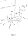
- the bearing device 7 comprises a fastening flange 9 on which a bearing journal 11 is formed.
- the fastening flange 9 is connected to the body 3 or the inner container 5, in particular screwed, so that the bearing device 7 is rigidly fixed to the body 3 or the inner container 5.
- a bearing bush 13 is slipped onto the bearing journal 11.
- the storage device 7 can have a height-adjustable stand 15.
- the bearing device 7 is together with the bearing bushing 13 and the base 15 in the Fig. 2 shown in more detail in an enlarged perspective illustration.
- the bearing bush 13 is shown in a position withdrawn from the bearing journal 11.
- the bearing device 7 is produced from a flat steel semi-finished product by punching the outer contour and bending the bearing journal 11.
- the bearing pin 11 is formed in one piece with the fastening flange 9.
- the fastening flange 9 and the bearing pin 11 are made as a bearing bracket from a stamped and bent sheet metal.
- the fastening flange 9 has a somewhat triangular basic shape, screw tabs 16 being formed on a long base side, via which the bearing device 7 can be rigidly screwed to the body 3 or the inner container 5.
- the bearing pin 11 is formed on a pointed end of the fastening flange 9 opposite the long base side.
- the bearing pin 11 is bent vertically upwards by 90 degrees out of the plane of the fastening flange 9, so that the bearing bush 13 can be slipped onto the bearing pin 11 in a vertical direction from above.
- the bearing journal 11 Due to the fact that the bearing journal 11 is produced as a bending section of the flat flat steel semi-finished product, the bearing journal 11 has a rectangular cross section.
- the bearing bushing 13 is fitted onto the bearing journal 11 with a rectangular cross-section, so that the fitted bearing bushing 13 forms the hinge pin due to its cylindrical outer contour.
- the base 15 has a screw head 17 which is connected to a threaded shaft 19.
- the household refrigeration device 1 a stands up with a screw head 17 of several, in particular two or four feet 15 on a floor.
- the threaded shaft 19 penetrates a threaded bore 21 of the fastening flange 9. By turning the screw head 17, the stand 15 can be adjusted in height.
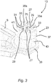
- the bearing bush 13 has, as in Fig. 3 shown in more detail, an at least substantially hollow cylindrical base body 23.
- the base body 23 has an inner jacket wall 25 which, in the exemplary embodiment shown, is equipped with a total of six webs 27 projecting from the inner jacket wall 25 of the base body 23 into the center of the bearing bush 13.
- the contour of the cross section of each web 27 has two corners 31 at right angles which delimit a straight front contour section of an end face 29 of the web 27.
- a clamping rib 35a according to the invention is formed on exactly one side wall 33 of two opposing webs 27 adjoining the end face 29, in particular in a corner 31.
- An outer jacket wall 37 of the bearing bush 13 has a straight cylindrical jacket wall section 43.
- the bearing bushing 13 has a radially projecting annular collar 39.
- the annular collar 39 can serve as a seat for the door leaf 6 of the household refrigerator 1 a.
- the bearing bushing 13 has a frustoconical jacket wall section 41.
- the frustoconical shell wall section 41 can serve to be able to easily center the bearing bushing 13 when it is inserted into a seat receptacle of the door leaf 6, or when the Door leaf 6 with its seat receptacle is slipped onto the bearing bush 13. In this respect, the assembly of the door leaf 6 on the bearing device 7 can be simplified.
- the webs 27, that is, their shape and size are adapted to the size, shape and contour of the clear opening 45 of the bearing bush 13 into which the bearing pin 11 is to be inserted, or the cross section of the bearing pin 11.
- the webs 27 thus limit the opening 45 of the bearing bush 13 to the dimension of the bearing journal 11.
- a clamping rib 35a according to the invention is formed on exactly one side wall 33 of two opposing webs 27 adjoining the end face 29, in particular in a corner 31.
- a single clamping rib 35a or two or more clamping ribs 35a can form the clamping device 35 according to the invention or at least be part of the clamping device 35.
- the clamping device 35 or the two clamping ribs 35a, are formed in one piece with the bearing bush 13.
- the two clamping ribs 35a are designed to protrude in the direction of the bearing journal 11.
- two clamping ribs 35a are formed on each side wall 33 of two webs 27.
- Each clamping rib 35a has a base section 47 connected to the bearing bushing 13 or to the respective web 27 of the bearing bushing 13, a free head section 49 resting on the bearing journal 11 and a web section 51 connecting the base section 47 to the head section 49.
- the web section 51 is oriented at an angle deviating from the right angle, in particular at an angle of 45 degrees, with respect to the surface 53 of the bearing journal 11.
- an inwardly projecting rib edge 55 of the clamping rib 35a extends with its free end beyond the end face 29 of the associated web 27.
- the clamping rib 35a is designed to be elastic in that its wall thickness is reduced in relation to the wall thickness of the base body 23 or in relation to the wall thickness of the web 27.
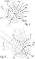
- the two clamping ribs 35a are elastically bent and it a spring tension force is established in the clamping ribs 35a.
- the spring tension force in turn presses against the bearing journal 11 from opposite sides and thereby clamps the bearing bushing 13 firmly on the bearing journal 11.
- two clamping ribs 35a protruding in the direction of the bearing journal 11 are therefore arranged on opposite inner webs 27 of the bearing bushing protruding into the center of the bearing bushing 11.
Landscapes
- Engineering & Computer Science (AREA)
- Mechanical Engineering (AREA)
- Chemical & Material Sciences (AREA)
- Combustion & Propulsion (AREA)
- Physics & Mathematics (AREA)
- Thermal Sciences (AREA)
- General Engineering & Computer Science (AREA)
- Refrigerator Housings (AREA)
- Clamps And Clips (AREA)
Claims (6)
- Appareil ménager, en particulier appareil frigorifique ménager (1a), présentant un corps (3), un espace d'appareil (8) disposé dans le corps (3) et un ouvrant (6) formé pour ouvrir et fermer l'espace d'appareil (8), lequel ouvrant est logé de façon pivotante par rapport au corps (3) au moyen d'au moins un dispositif de palier (7), qui présente un tourillon (11) et un coussinet (13) inséré sur le tourillon (11), dans lequel le dispositif de palier (7) présente un dispositif de pincement (35), formé afin de maintenir dans sa position insérée sur le tourillon (11) le coussinet (13) sur le tourillon (11), dans lequel le coussinet présente un contour extérieur au moins essentiellement cylindrique circulaire et le tourillon présente un contour transversal rectangulaire, dans lequel le coussinet (13) présente le dispositif de pincement (35), dans lequel le coussinet (13) présente au centre du coussinet (13) des âmes (27) intérieures opposées saillantes, dans lequel le dispositif de pincement (35) est formé par deux nervures de pincement (35a) formées élastiquement, en particulier fabriquées en un matériau élastique, dont les épaisseurs de paroi sont réduites par rapport à l'épaisseur de paroi du corps de base (23) et/ou d'une âme (27) du coussinet (13) et disposées sur les âmes (27), de sorte que le tourillon (11) est pincé en deux côtés opposés, dans lequel le coussinet (13) présente un corps de base (23) essentiellement cylindrique creux, qui présente une paroi de manteau intérieure (25), dans lequel la paroi de manteau (25) présente les âmes (27), caractérisé en ce que le contour de la section d'une âme (27) présente deux angles droits, qui délimitent une section de contour frontale droite d'une surface frontale (29) de l'âme (27), et la nervure de pincement (35a) est disposée, en particulier formée, en au moins une paroi latérale (33) de l'âme (27) contiguë à la surface frontale (29), en particulier à angle droit et en ce que les nervures de pincement (35a) présentent en leurs extrémités libres des bords de nervure (55) faisant saillie vers l'intérieur sur la surface frontale (29) de l'âme (27).
- Appareil ménager selon la revendication 1, caractérisé en ce que le dispositif de pincement (35) est relié au coussinet (13) ou formé en une seule pièce avec le coussinet (13).
- Appareil ménager selon l'une des revendications précédentes, caractérisé en ce que les nervures de pincement (35a) présentent une section de base (47) reliée au coussinet (13), une section de tête (49) libre contiguë au tourillon (11) et une section d'âme (51) reliant la section de base (47) à la section de tête (49), laquelle section d'âme est orientée selon un angle divergeant de l'angle droit, en particulier selon un angle de 45 degrés, par rapport à une surface (53) du tourillon (11).
- Appareil ménager selon l'une des revendications précédentes, caractérisé en ce que la nervure de pincement (35a) est disposée, en particulier formée, sur précisément une paroi latérale (33) de l'âme (27) contiguë à la surface frontale (29), en particulier à angle droit.
- Appareil ménager selon l'une des revendications précédentes, caractérisé en ce que deux nervures de pincement (35a) faisant saillie en direction du tourillon (11) sont disposées en des côtés opposés d'une paroi de manteau intérieure (25) du coussinet (13).
- Appareil ménager selon l'une des revendications précédentes, caractérisé en ce que les nervures de pincement (35a) sont fabriquées en une seule pièce avec le coussinet (13), en particulier en plastique.
Applications Claiming Priority (2)
| Application Number | Priority Date | Filing Date | Title |
|---|---|---|---|
| DE102012202440A DE102012202440A1 (de) | 2012-02-17 | 2012-02-17 | Haushaltsgerät mit einer Türblatt-Lagervorrichtung |
| PCT/EP2013/052437 WO2013120761A1 (fr) | 2012-02-17 | 2013-02-07 | Appareil électroménager pourvu d'un dispositif de montage de porte |
Publications (2)
| Publication Number | Publication Date |
|---|---|
| EP2815049A1 EP2815049A1 (fr) | 2014-12-24 |
| EP2815049B1 true EP2815049B1 (fr) | 2021-07-14 |
Family
ID=47749786
Family Applications (1)
| Application Number | Title | Priority Date | Filing Date |
|---|---|---|---|
| EP13705950.7A Active EP2815049B1 (fr) | 2012-02-17 | 2013-02-07 | Appareil ménager avec un elément de palier de battant |
Country Status (4)
| Country | Link |
|---|---|
| EP (1) | EP2815049B1 (fr) |
| CN (1) | CN104285024B (fr) |
| DE (1) | DE102012202440A1 (fr) |
| WO (1) | WO2013120761A1 (fr) |
Families Citing this family (4)
| Publication number | Priority date | Publication date | Assignee | Title |
|---|---|---|---|---|
| DE102013216804A1 (de) * | 2013-08-23 | 2015-02-26 | BSH Bosch und Siemens Hausgeräte GmbH | Haushaltsgerät mit einer Türblattlagerung |
| CN110748258A (zh) * | 2019-11-05 | 2020-02-04 | 合肥晶弘电器有限公司 | 铰链组件、能调节门体高度的冰箱 |
| TR201920958A2 (tr) * | 2019-12-20 | 2021-06-21 | Bsh Ev Aletleri San Ve Tic As | Bi̇r soğutucu ci̇haz i̇çi̇n yatak braketi̇ ve buna i̇li̇şki̇n bi̇r üreti̇m yöntemi̇ |
| DE102020213908A1 (de) * | 2020-11-05 | 2022-05-05 | BSH Hausgeräte GmbH | Haushaltsgerät mit einem symmetrischen Lagerwinkel eines Scharniers für eine Tür, sowie Verfahren |
Family Cites Families (11)
| Publication number | Priority date | Publication date | Assignee | Title |
|---|---|---|---|---|
| US3438660A (en) * | 1964-10-23 | 1969-04-15 | Lajos Steiner | Mechanical clamping means |
| US3880536A (en) * | 1974-03-18 | 1975-04-29 | Eaton Corp | Hub construction |
| DE4124805C2 (de) * | 1991-07-26 | 1998-07-02 | Aeg Hausgeraete Gmbh | Kühl- oder Gefrierschrank |
| JP3188126B2 (ja) * | 1995-02-10 | 2001-07-16 | 三洋電機株式会社 | 冷蔵庫の扉キャップ |
| US5928763A (en) * | 1995-07-13 | 1999-07-27 | The Grigoleit Company | Method for obtaining a tight, secure connection between interfitting members and the connection resulting therefrom |
| DE19723077B4 (de) * | 1997-06-02 | 2006-08-17 | BSH Bosch und Siemens Hausgeräte GmbH | Lagerung für eine verschwenkbare Tür eines Haushaltsgerätes |
| DE10259065B4 (de) * | 2002-12-17 | 2011-04-28 | BSH Bosch und Siemens Hausgeräte GmbH | Türscharnier und Lagerungsbuchse |
| DE202004007067U1 (de) * | 2004-05-04 | 2004-06-24 | BSH Bosch und Siemens Hausgeräte GmbH | Hohlachsiges Scharnier |
| DE102008021343A1 (de) * | 2008-04-29 | 2009-11-05 | BSH Bosch und Siemens Hausgeräte GmbH | Haushaltsgerät |
| DE102008043811A1 (de) | 2008-11-18 | 2010-05-20 | BSH Bosch und Siemens Hausgeräte GmbH | Haushaltsgerät mit Lagerzapfen mit Verdrehsicherung für Lagerbuchse |
| EP2543806A1 (fr) * | 2011-07-04 | 2013-01-09 | Electrolux Home Products Corporation N.V. | Appareil domestique avec ensemble de charnière améliorée |
-
2012
- 2012-02-17 DE DE102012202440A patent/DE102012202440A1/de not_active Withdrawn
-
2013
- 2013-02-07 EP EP13705950.7A patent/EP2815049B1/fr active Active
- 2013-02-07 WO PCT/EP2013/052437 patent/WO2013120761A1/fr not_active Ceased
- 2013-02-07 CN CN201380009824.9A patent/CN104285024B/zh active Active
Non-Patent Citations (1)
| Title |
|---|
| None * |
Also Published As
| Publication number | Publication date |
|---|---|
| CN104285024A (zh) | 2015-01-14 |
| WO2013120761A1 (fr) | 2013-08-22 |
| DE102012202440A1 (de) | 2013-08-22 |
| CN104285024B (zh) | 2017-07-18 |
| EP2815049A1 (fr) | 2014-12-24 |
Similar Documents
| Publication | Publication Date | Title |
|---|---|---|
| EP3602708B1 (fr) | Ossature d'armoire électrique avec socle | |
| EP1869334B1 (fr) | Palier lisse, systeme de palier lisse et montage d'un systeme de palier lisse | |
| DE102012009173B4 (de) | Toleranzausgleichseinrichtung | |
| EP3622153B1 (fr) | Commande de meuble à moteur | |
| DE112016000191T5 (de) | Befestigungsclipanordnung | |
| DE102016117378B3 (de) | Scharnieranordnung für einen Schaltschrank | |
| DE102018108978A1 (de) | Ablageboden und Möbel oder Haushaltsgerät | |
| EP1592323B1 (fr) | Ensemble de rails telescopiques et appareil frigorifique pourvu d'un tel ensemble | |
| EP2334512B1 (fr) | Element miroir | |
| EP2195480B1 (fr) | Lave-linge | |
| WO2013120761A1 (fr) | Appareil électroménager pourvu d'un dispositif de montage de porte | |
| EP1884382A1 (fr) | Amortisseur d'oscillations doté d'une fixation | |
| WO2016050464A1 (fr) | Dispositif de guidage pour le guidage d'une porte coulissante et armoire de mobilier | |
| WO2012116785A1 (fr) | Siège de véhicule | |
| EP3332133B1 (fr) | Écrou prisonnier | |
| DE10361548B4 (de) | Türband | |
| WO2013153091A1 (fr) | Support de toit pour un porte-bagages de toit pouvant être fixé sur celui-ci | |
| AT520767B1 (de) | Anordnung aus einem Auflagesteg für einen Schubladenboden und einer Haltevorrichtung | |
| EP2060379B1 (fr) | Support offrant une isolation vibratoire | |
| DE102018201493B4 (de) | Verkleidungsteil für ein Kraftfahrzeug und Verwendung | |
| DE102010038835B4 (de) | Vorrichtung zur Aufhängung einer Abgasanlage an einem Fahrzeugboden eines KFZ | |
| DE102012112362C5 (de) | Ventil mit einer Befestigungseinrichtung | |
| EP3727091B1 (fr) | Arrangement comprenant une tringle et un element mural d'un tiroir | |
| EP3045617B1 (fr) | Rosette et système de loquet de porte ou de fenêtre et d'une rosette sur une ouverture de vantail de fenêtre ou de porte ou similaire | |
| EP3824760B1 (fr) | Meuble |
Legal Events
| Date | Code | Title | Description |
|---|---|---|---|
| PUAI | Public reference made under article 153(3) epc to a published international application that has entered the european phase |
Free format text: ORIGINAL CODE: 0009012 |
|
| 17P | Request for examination filed |
Effective date: 20140917 |
|
| AK | Designated contracting states |
Kind code of ref document: A1 Designated state(s): AL AT BE BG CH CY CZ DE DK EE ES FI FR GB GR HR HU IE IS IT LI LT LU LV MC MK MT NL NO PL PT RO RS SE SI SK SM TR |
|
| AX | Request for extension of the european patent |
Extension state: BA ME |
|
| RAP1 | Party data changed (applicant data changed or rights of an application transferred) |
Owner name: BSH HAUSGERAETE GMBH |
|
| DAX | Request for extension of the european patent (deleted) | ||
| STAA | Information on the status of an ep patent application or granted ep patent |
Free format text: STATUS: EXAMINATION IS IN PROGRESS |
|
| 17Q | First examination report despatched |
Effective date: 20170922 |
|
| GRAP | Despatch of communication of intention to grant a patent |
Free format text: ORIGINAL CODE: EPIDOSNIGR1 |
|
| STAA | Information on the status of an ep patent application or granted ep patent |
Free format text: STATUS: GRANT OF PATENT IS INTENDED |
|
| INTG | Intention to grant announced |
Effective date: 20210222 |
|
| GRAS | Grant fee paid |
Free format text: ORIGINAL CODE: EPIDOSNIGR3 |
|
| GRAA | (expected) grant |
Free format text: ORIGINAL CODE: 0009210 |
|
| STAA | Information on the status of an ep patent application or granted ep patent |
Free format text: STATUS: THE PATENT HAS BEEN GRANTED |
|
| AK | Designated contracting states |
Kind code of ref document: B1 Designated state(s): AL AT BE BG CH CY CZ DE DK EE ES FI FR GB GR HR HU IE IS IT LI LT LU LV MC MK MT NL NO PL PT RO RS SE SI SK SM TR |
|
| REG | Reference to a national code |
Ref country code: GB Ref legal event code: FG4D Free format text: NOT ENGLISH |
|
| REG | Reference to a national code |
Ref country code: IE Ref legal event code: FG4D Free format text: LANGUAGE OF EP DOCUMENT: GERMAN |
|
| REG | Reference to a national code |
Ref country code: DE Ref legal event code: R096 Ref document number: 502013015826 Country of ref document: DE |
|
| REG | Reference to a national code |
Ref country code: AT Ref legal event code: REF Ref document number: 1410785 Country of ref document: AT Kind code of ref document: T Effective date: 20210815 |
|
| REG | Reference to a national code |
Ref country code: LT Ref legal event code: MG9D |
|
| REG | Reference to a national code |
Ref country code: NL Ref legal event code: MP Effective date: 20210714 |
|
| PG25 | Lapsed in a contracting state [announced via postgrant information from national office to epo] |
Ref country code: LT Free format text: LAPSE BECAUSE OF FAILURE TO SUBMIT A TRANSLATION OF THE DESCRIPTION OR TO PAY THE FEE WITHIN THE PRESCRIBED TIME-LIMIT Effective date: 20210714 Ref country code: BG Free format text: LAPSE BECAUSE OF FAILURE TO SUBMIT A TRANSLATION OF THE DESCRIPTION OR TO PAY THE FEE WITHIN THE PRESCRIBED TIME-LIMIT Effective date: 20211014 Ref country code: NL Free format text: LAPSE BECAUSE OF FAILURE TO SUBMIT A TRANSLATION OF THE DESCRIPTION OR TO PAY THE FEE WITHIN THE PRESCRIBED TIME-LIMIT Effective date: 20210714 Ref country code: PT Free format text: LAPSE BECAUSE OF FAILURE TO SUBMIT A TRANSLATION OF THE DESCRIPTION OR TO PAY THE FEE WITHIN THE PRESCRIBED TIME-LIMIT Effective date: 20211115 Ref country code: NO Free format text: LAPSE BECAUSE OF FAILURE TO SUBMIT A TRANSLATION OF THE DESCRIPTION OR TO PAY THE FEE WITHIN THE PRESCRIBED TIME-LIMIT Effective date: 20211014 Ref country code: RS Free format text: LAPSE BECAUSE OF FAILURE TO SUBMIT A TRANSLATION OF THE DESCRIPTION OR TO PAY THE FEE WITHIN THE PRESCRIBED TIME-LIMIT Effective date: 20210714 Ref country code: ES Free format text: LAPSE BECAUSE OF FAILURE TO SUBMIT A TRANSLATION OF THE DESCRIPTION OR TO PAY THE FEE WITHIN THE PRESCRIBED TIME-LIMIT Effective date: 20210714 Ref country code: FI Free format text: LAPSE BECAUSE OF FAILURE TO SUBMIT A TRANSLATION OF THE DESCRIPTION OR TO PAY THE FEE WITHIN THE PRESCRIBED TIME-LIMIT Effective date: 20210714 Ref country code: HR Free format text: LAPSE BECAUSE OF FAILURE TO SUBMIT A TRANSLATION OF THE DESCRIPTION OR TO PAY THE FEE WITHIN THE PRESCRIBED TIME-LIMIT Effective date: 20210714 Ref country code: SE Free format text: LAPSE BECAUSE OF FAILURE TO SUBMIT A TRANSLATION OF THE DESCRIPTION OR TO PAY THE FEE WITHIN THE PRESCRIBED TIME-LIMIT Effective date: 20210714 |
|
| PG25 | Lapsed in a contracting state [announced via postgrant information from national office to epo] |
Ref country code: PL Free format text: LAPSE BECAUSE OF FAILURE TO SUBMIT A TRANSLATION OF THE DESCRIPTION OR TO PAY THE FEE WITHIN THE PRESCRIBED TIME-LIMIT Effective date: 20210714 Ref country code: LV Free format text: LAPSE BECAUSE OF FAILURE TO SUBMIT A TRANSLATION OF THE DESCRIPTION OR TO PAY THE FEE WITHIN THE PRESCRIBED TIME-LIMIT Effective date: 20210714 Ref country code: GR Free format text: LAPSE BECAUSE OF FAILURE TO SUBMIT A TRANSLATION OF THE DESCRIPTION OR TO PAY THE FEE WITHIN THE PRESCRIBED TIME-LIMIT Effective date: 20211015 |
|
| REG | Reference to a national code |
Ref country code: DE Ref legal event code: R097 Ref document number: 502013015826 Country of ref document: DE |
|
| PG25 | Lapsed in a contracting state [announced via postgrant information from national office to epo] |
Ref country code: DK Free format text: LAPSE BECAUSE OF FAILURE TO SUBMIT A TRANSLATION OF THE DESCRIPTION OR TO PAY THE FEE WITHIN THE PRESCRIBED TIME-LIMIT Effective date: 20210714 |
|
| PLBE | No opposition filed within time limit |
Free format text: ORIGINAL CODE: 0009261 |
|
| STAA | Information on the status of an ep patent application or granted ep patent |
Free format text: STATUS: NO OPPOSITION FILED WITHIN TIME LIMIT |
|
| PG25 | Lapsed in a contracting state [announced via postgrant information from national office to epo] |
Ref country code: SM Free format text: LAPSE BECAUSE OF FAILURE TO SUBMIT A TRANSLATION OF THE DESCRIPTION OR TO PAY THE FEE WITHIN THE PRESCRIBED TIME-LIMIT Effective date: 20210714 Ref country code: SK Free format text: LAPSE BECAUSE OF FAILURE TO SUBMIT A TRANSLATION OF THE DESCRIPTION OR TO PAY THE FEE WITHIN THE PRESCRIBED TIME-LIMIT Effective date: 20210714 Ref country code: RO Free format text: LAPSE BECAUSE OF FAILURE TO SUBMIT A TRANSLATION OF THE DESCRIPTION OR TO PAY THE FEE WITHIN THE PRESCRIBED TIME-LIMIT Effective date: 20210714 Ref country code: EE Free format text: LAPSE BECAUSE OF FAILURE TO SUBMIT A TRANSLATION OF THE DESCRIPTION OR TO PAY THE FEE WITHIN THE PRESCRIBED TIME-LIMIT Effective date: 20210714 Ref country code: CZ Free format text: LAPSE BECAUSE OF FAILURE TO SUBMIT A TRANSLATION OF THE DESCRIPTION OR TO PAY THE FEE WITHIN THE PRESCRIBED TIME-LIMIT Effective date: 20210714 Ref country code: AL Free format text: LAPSE BECAUSE OF FAILURE TO SUBMIT A TRANSLATION OF THE DESCRIPTION OR TO PAY THE FEE WITHIN THE PRESCRIBED TIME-LIMIT Effective date: 20210714 |
|
| 26N | No opposition filed |
Effective date: 20220419 |
|
| PG25 | Lapsed in a contracting state [announced via postgrant information from national office to epo] |
Ref country code: IT Free format text: LAPSE BECAUSE OF FAILURE TO SUBMIT A TRANSLATION OF THE DESCRIPTION OR TO PAY THE FEE WITHIN THE PRESCRIBED TIME-LIMIT Effective date: 20210714 |
|
| PG25 | Lapsed in a contracting state [announced via postgrant information from national office to epo] |
Ref country code: MC Free format text: LAPSE BECAUSE OF FAILURE TO SUBMIT A TRANSLATION OF THE DESCRIPTION OR TO PAY THE FEE WITHIN THE PRESCRIBED TIME-LIMIT Effective date: 20210714 |
|
| REG | Reference to a national code |
Ref country code: CH Ref legal event code: PL |
|
| REG | Reference to a national code |
Ref country code: BE Ref legal event code: MM Effective date: 20220228 |
|
| GBPC | Gb: european patent ceased through non-payment of renewal fee |
Effective date: 20220207 |
|
| PG25 | Lapsed in a contracting state [announced via postgrant information from national office to epo] |
Ref country code: LU Free format text: LAPSE BECAUSE OF NON-PAYMENT OF DUE FEES Effective date: 20220207 |
|
| PG25 | Lapsed in a contracting state [announced via postgrant information from national office to epo] |
Ref country code: FR Free format text: LAPSE BECAUSE OF NON-PAYMENT OF DUE FEES Effective date: 20220228 |
|
| PG25 | Lapsed in a contracting state [announced via postgrant information from national office to epo] |
Ref country code: LI Free format text: LAPSE BECAUSE OF NON-PAYMENT OF DUE FEES Effective date: 20220228 Ref country code: IE Free format text: LAPSE BECAUSE OF NON-PAYMENT OF DUE FEES Effective date: 20220207 Ref country code: GB Free format text: LAPSE BECAUSE OF NON-PAYMENT OF DUE FEES Effective date: 20220207 Ref country code: CH Free format text: LAPSE BECAUSE OF NON-PAYMENT OF DUE FEES Effective date: 20220228 |
|
| PG25 | Lapsed in a contracting state [announced via postgrant information from national office to epo] |
Ref country code: BE Free format text: LAPSE BECAUSE OF NON-PAYMENT OF DUE FEES Effective date: 20220228 |
|
| REG | Reference to a national code |
Ref country code: AT Ref legal event code: MM01 Ref document number: 1410785 Country of ref document: AT Kind code of ref document: T Effective date: 20220207 |
|
| PG25 | Lapsed in a contracting state [announced via postgrant information from national office to epo] |
Ref country code: AT Free format text: LAPSE BECAUSE OF NON-PAYMENT OF DUE FEES Effective date: 20220207 |
|
| PG25 | Lapsed in a contracting state [announced via postgrant information from national office to epo] |
Ref country code: HU Free format text: LAPSE BECAUSE OF FAILURE TO SUBMIT A TRANSLATION OF THE DESCRIPTION OR TO PAY THE FEE WITHIN THE PRESCRIBED TIME-LIMIT; INVALID AB INITIO Effective date: 20130207 |
|
| PG25 | Lapsed in a contracting state [announced via postgrant information from national office to epo] |
Ref country code: MK Free format text: LAPSE BECAUSE OF FAILURE TO SUBMIT A TRANSLATION OF THE DESCRIPTION OR TO PAY THE FEE WITHIN THE PRESCRIBED TIME-LIMIT Effective date: 20210714 Ref country code: CY Free format text: LAPSE BECAUSE OF FAILURE TO SUBMIT A TRANSLATION OF THE DESCRIPTION OR TO PAY THE FEE WITHIN THE PRESCRIBED TIME-LIMIT Effective date: 20210714 |
|
| PG25 | Lapsed in a contracting state [announced via postgrant information from national office to epo] |
Ref country code: MT Free format text: LAPSE BECAUSE OF FAILURE TO SUBMIT A TRANSLATION OF THE DESCRIPTION OR TO PAY THE FEE WITHIN THE PRESCRIBED TIME-LIMIT Effective date: 20210714 |
|
| PGFP | Annual fee paid to national office [announced via postgrant information from national office to epo] |
Ref country code: DE Payment date: 20260228 Year of fee payment: 14 |
|
| PGFP | Annual fee paid to national office [announced via postgrant information from national office to epo] |
Ref country code: TR Payment date: 20260205 Year of fee payment: 14 |