EP2815080B1 - Verdrehsichere statoranordnung - Google Patents
Verdrehsichere statoranordnung Download PDFInfo
- Publication number
- EP2815080B1 EP2815080B1 EP13749337.5A EP13749337A EP2815080B1 EP 2815080 B1 EP2815080 B1 EP 2815080B1 EP 13749337 A EP13749337 A EP 13749337A EP 2815080 B1 EP2815080 B1 EP 2815080B1
- Authority
- EP
- European Patent Office
- Prior art keywords
- case
- aft
- stator
- central portion
- slot
- Prior art date
- Legal status (The legal status is an assumption and is not a legal conclusion. Google has not performed a legal analysis and makes no representation as to the accuracy of the status listed.)
- Active
Links
Images


Classifications
-
- F—MECHANICAL ENGINEERING; LIGHTING; HEATING; WEAPONS; BLASTING
- F01—MACHINES OR ENGINES IN GENERAL; ENGINE PLANTS IN GENERAL; STEAM ENGINES
- F01D—NON-POSITIVE DISPLACEMENT MACHINES OR ENGINES, e.g. STEAM TURBINES
- F01D25/00—Component parts, details, or accessories, not provided for in, or of interest apart from, other groups
- F01D25/24—Casings; Casing parts, e.g. diaphragms, casing fastenings
- F01D25/246—Fastening of diaphragms or stator-rings
-
- F—MECHANICAL ENGINEERING; LIGHTING; HEATING; WEAPONS; BLASTING
- F01—MACHINES OR ENGINES IN GENERAL; ENGINE PLANTS IN GENERAL; STEAM ENGINES
- F01D—NON-POSITIVE DISPLACEMENT MACHINES OR ENGINES, e.g. STEAM TURBINES
- F01D9/00—Stators
- F01D9/02—Nozzles; Nozzle boxes; Stator blades; Guide conduits, e.g. individual nozzles
- F01D9/04—Nozzles; Nozzle boxes; Stator blades; Guide conduits, e.g. individual nozzles forming ring or sector
- F01D9/042—Nozzles; Nozzle boxes; Stator blades; Guide conduits, e.g. individual nozzles forming ring or sector fixing blades to stators
-
- F—MECHANICAL ENGINEERING; LIGHTING; HEATING; WEAPONS; BLASTING
- F05—INDEXING SCHEMES RELATING TO ENGINES OR PUMPS IN VARIOUS SUBCLASSES OF CLASSES F01-F04
- F05D—INDEXING SCHEME FOR ASPECTS RELATING TO NON-POSITIVE-DISPLACEMENT MACHINES OR ENGINES, GAS-TURBINES OR JET-PROPULSION PLANTS
- F05D2240/00—Components
- F05D2240/10—Stators
- F05D2240/12—Fluid guiding means, e.g. vanes
-
- F—MECHANICAL ENGINEERING; LIGHTING; HEATING; WEAPONS; BLASTING
- F05—INDEXING SCHEMES RELATING TO ENGINES OR PUMPS IN VARIOUS SUBCLASSES OF CLASSES F01-F04
- F05D—INDEXING SCHEME FOR ASPECTS RELATING TO NON-POSITIVE-DISPLACEMENT MACHINES OR ENGINES, GAS-TURBINES OR JET-PROPULSION PLANTS
- F05D2240/00—Components
- F05D2240/80—Platforms for stationary or moving blades
-
- F—MECHANICAL ENGINEERING; LIGHTING; HEATING; WEAPONS; BLASTING
- F05—INDEXING SCHEMES RELATING TO ENGINES OR PUMPS IN VARIOUS SUBCLASSES OF CLASSES F01-F04
- F05D—INDEXING SCHEME FOR ASPECTS RELATING TO NON-POSITIVE-DISPLACEMENT MACHINES OR ENGINES, GAS-TURBINES OR JET-PROPULSION PLANTS
- F05D2260/00—Function
- F05D2260/30—Retaining components in desired mutual position
-
- Y—GENERAL TAGGING OF NEW TECHNOLOGICAL DEVELOPMENTS; GENERAL TAGGING OF CROSS-SECTIONAL TECHNOLOGIES SPANNING OVER SEVERAL SECTIONS OF THE IPC; TECHNICAL SUBJECTS COVERED BY FORMER USPC CROSS-REFERENCE ART COLLECTIONS [XRACs] AND DIGESTS
- Y02—TECHNOLOGIES OR APPLICATIONS FOR MITIGATION OR ADAPTATION AGAINST CLIMATE CHANGE
- Y02T—CLIMATE CHANGE MITIGATION TECHNOLOGIES RELATED TO TRANSPORTATION
- Y02T50/00—Aeronautics or air transport
- Y02T50/60—Efficient propulsion technologies, e.g. for aircraft
Definitions
- a gas turbine engine is disclosed with a stator that is prevented from circumferentially rotating about the axis of the engine and/or along the case that holds the stator in place.
- a gas turbine engine includes one or more forward compressor sections for increasing the pressure of an incoming air stream.
- a turbofan jet engine includes a low pressure compressor (LPC) disposed between fan at the inlet of the engine and a high pressure compressor (HPC).
- LPC low pressure compressor
- HPC high pressure compressor
- Each compressor includes alternating axial stages of rotors and stators.
- Each stator is disposed within a circumferential case.
- Each rotor may include an outer ring of rotating blades; each stator may include a ring of stator segments, with each segment including a shroud connected to an individual vane or a shroud connected to a plurality of vanes.
- Each shroud may include forward and aft hooks for coupling the segment to the case.
- each shroud may include forward and aft hooks that are received in forward and aft circumferential slots of the case.
- each segment is inserted into the case by inserting the forward and aft hooks of each segment into the corresponding forward and aft circumferential slots of the case.
- the case may be split into forward and aft portions or the case may be a unitary ring structure.
- each stator segment During normal operation of a gas turbine engine, the combination of temperature variations between the case and the stator segments and the tolerances built into each separate part (i.e., the stator segments and the case) necessitate a suitable cold-clearance gap between adjacent stator segments. Further, aerodynamic loading of each stator segment generates a tangential force approaching 90N (20 lb ⁇ f) per airfoil included in the segment.
- anti-rotation lugs, bolts or pins may be employed for each segment or one or more anti-rotation lugs may be circumferentially spaced around the case to prevent rotation of the segments along the case.
- the lugs may be fastened to the case so that the lug is disposed between two segments and contacts a shroud on each of the two segments.
- the anti-rotation lugs may also facilitate assembly and the positioning of each segment in the case.
- the anti-rotation lug must engage two segments and a portion of the shrouds of each of the two segments must be removed to form a slot or recess for accommodating the lug.
- Removing part of the shroud, or more specifically, the platform portion of the shroud disposed between the forward and aft hooks results in removal of part of the one of the forward or aft hooks (more commonly the aft hook).
- Removing part of the aft hook renders the pair of stator segments less stable within the case which reduces the ability to control the circumferential position of the locking stator segments.
- US 2003/0068225A1 discloses a nozzle lock for securing a nozzle segment relative to the engine casing of a gas turbine engine.
- US 5,201,846A discloses a mechanism provided for blocking axial rotation and displacement of a heat shield of an axial flow gas turbine engine.
- US 4,687,413A discloses the use of C-shaped couplings to secure annular, circumferentially segmented components of a gas turbine engine to a support structure, preventing movement of the components in a radial and circumferential direction.
- EP 2613021 A2 discloses a stator subassembly including an array of circumferentially arranged stator vanes, and a damper spring provided between the array and an outer case.
- stator assembly coupled to an engine shroud of a gas turbine engine, the stator assembly for preventing circumferential movement of stator segments, the stator assembly comprising an endless case fixedly coupled to the engine shroud, the case including a forward portion, an aft portion and a central portion disposed therebetween, the case extending around an axis, the forward and aft portions of the case forming forward and aft pockets with the central portion respectively, a locking stator segment, the locking stator segment including a shroud connected to a vane, the shroud of the locking stator segment including a forward hook and a pair of aft hooks; the shroud of the locking stator segment including a slot that extends between the aft hooks and accommodates a lug, the lug being coupled to the case; wherein the forward and aft portions of the case extend towards each other; wherein the forward and aft hooks are retained in the forward and aft pockets respectively
- the present invention also provides a gas turbine engine that includes a stator assembly as outlined above.
- the forward portion of the case includes a rearwardly directed rail; the aft portion of the case includes forwardly directed rail.
- the rearwardly directed rail of the forward portion and the forwardly directed rail of the aft portion extend towards each other beneath the central portion of the case and form forward and aft pockets respectively.
- the forward and aft pockets accommodate forward and aft liners respectively.
- the present invention also provides a method for preventing a circumferential movement of stator segments of a stator assembly of a gas turbine engine, the method comprising, providing the stator assembly with an endless case, fixedly coupling the endless case to a shroud of the engine, the case including a forward portion, an aft portion and a central portion disposed therebetween, the case extending around an axis of the engine, providing the forward portion of the case with a rearwardly extending case rail and the aft portion of the case with a forwardly extending case rail, the forward and aft case rails and the central portion of the case forming forward and aft pockets respectively, providing a locking stator segment, the locking stator segment including a shroud that includes a forward hook and a pair of aft hooks, the forward and aft hooks being retained in the forward and aft pockets of the case respectively, providing the shroud of the locking stator segment with a slot that extends between the aft
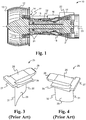
- the gas turbine engine 10 includes a fan 11 disposed within an outer housing or shroud 12, which is only partially shown in FIG. 1 .
- the fan 11 compresses intake air that enters through the housing opening 13 and feeds the compressed air to a low pressure compressor (LPC) 14.
- LPC low pressure compressor
- HPC high pressure compressor
- the HPC 15 is disposed between the LPC 14 and a combustor 16.
- the air, which has been compressed by the LPC 14 and HPC 15 is mixed with fuel and ignited to generate a high energy and high velocity stream of gases that flows through a turbine 17. Energy from the stream of gases passing through the turbine 17 is used to drive the LPC 14 and HPC 15.
- the LPC 14, HPC 15, combustor 16 and turbine 17 are housed within an inner shroud 18.
- the LPC 14, HPC 15 and turbine 17 each include a plurality of rotors, shown generally at 21, that rotate between stationary stators, shown generally at 22.
- the dynamic loading of each stator 22 caused by the rotors 21 can generate tangential forces or circumferential forces about the central axis 23 of the engine 10 that can approach 2225N (500 lb ⁇ f).
- Disclosed herein is a convenient means for preventing any circumferential rotation of the stators 22 about the axis 23.
- a segment 25 includes a shroud which, in turn, includes a platform 26, a forward hook 27, an aft hook 28, and a vane 29 that extends below the platform 26.
- the vane 29 includes a leading edge 31 and a trailing edge 32.
- the platform 26 is disposed between a pair of cheeks 34, 35 and each platform includes opposing sidewalls 38, 39 disposed inwardly from the cheeks 34, 35.
- the sidewalls 38, 39 are used to engage a bolt or lug that extends downward from the case to prevent circumferential movement of the segments 25 along the case.
- the sidewalls 38, 39 must be offset from the cheeks 34, 35 and the aft hook 28 is made narrower than the forward hook 27. The narrower aft hook 28 is positionally less stable and prone to rocking, thereby making precise control of the position of the locking stator segments 25 difficult.
- the segments 25 form an endless ring or a stator 22 ( FIG. 1 ).
- the segments 25 are slidably received in a case 36, four of which are shown in FIG. 2 .
- the forward hooks 27 are trapped in rearward facing pockets in the cases 36 and the aft hooks 28 are trapped in similar forward facing pockets of the cases 36.
- a means for preventing circumferential rotation of the stator segments is needed.
- bolts or fasteners 37 are used for this purpose.
- the bolts or fasteners 37 extend through the case 36 so that segments 25 disposed on either side of the bolt or fastener 37 is secured circumferentially within the case 36 to prevent circumferential sliding of the segments 25 around the case 36 and about the axis 23.
- the cases 36 are secured to the engine shroud 18 by one or more brackets 40 which are secured to the cases 36 by bolts or fasteners 41.
- the brackets 40 are then secured to the engine shroud 18 by supports, such as the one shown at 42 in FIG. 2 .
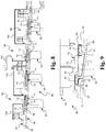
- a case 50 includes a forward portion 51, an aft portion 52 and a central portion 53 disposed therebetween.
- a damper spring 54 may be disposed below the central portion 53 for exerting a radially inward bias on the shrouds of the non-locking stator segments.
- the central portion 53 of the case 50 is sandwiched between the forward portion 51 and the aft portion 52, only parts of which are shown in FIG. 9 .
- the forward portion 51 of the case 50 includes a rearwardly directed rail 56.
- the rearwardly directed rail 56 in combination with the central portion 53 forms a forward pocket 57.
- An aft pocket 58 is also formed by the central portion 53 of the case 50 and a forwardly extending rail 61 of the aft portion 52 of the case 50.
- the locking segments 62 shown in FIGS. 8-9 and FIG. 6 each include a forward hook 63 and a pair of aft hooks shown at 64.
- the aft hooks 64 are extensions of the outwardly protruding members 65 of the shroud 60 which define a slot 66 as shown in FIG. 6.
- FIG. 6 also shows a vane 129 having a leading edge 131 and a trailing edge 132, similar to those shown in FIGS. 3-4 . Comparing FIGS.
- the aft hooks 64 are received in the aft pocket 58 while the forward hook 63 is received in the forward pocket 57.
- forward and aft liners 68, 69 are employed to assist in frictionally securing the forward and aft hooks 63, 64 and the forward and aft pockets 57, 58 respectively.
- the slot 66 of the locking segment 62 may receive a lug 70 as shown in FIG. 7 .
- the lug 70 includes an inner block 71 that is received in the slot 66 and an outwardly protruding stud 72.
- FIG. 5 An alternative lug 170 is shown in FIG. 5 with an inner block 171 and outwardly protruding stud 172.
- the protruding stud 72, 172 is integrally connected to the central portion 53 of the case 50.
- the studs 72 extend upward from the inner blocks 71 and are received in a gap, slot or recess 73 in the central portion 53 of the case 50.
- the locking segments 62 may be disposed between two stator segments and the central portions 53 of the cases 50 may include a gap, slot or recess 73 through which the protruding studs 72 extend.
- an anti-rotation stator segment system whereby the stator segments are held in place by locking segments 62 that are prevented from circumferential movement about the cases 50 by engagement of the outwardly protruding studs 72 of the lugs 70 engaging the central portion 53 of the case 50 and the slot 66 of a locking stator segment 62, which may be disposed between two conventional stator segments.
- the anti-rotation slot 66 of the locking stator segments 62 and mating lug 70 are disposed in the circumferential center of the locking stator segment shroud 60 ( FIG. 6 ) and not at the outer edges of two segments 25 as shown in FIGS. 3 and 4 .
- the disclosed locking stator segments 62 provide better location control of the segments 62 in the case 50 because the hooks 63, 64 of the segments 62 that engage the case 50 have not been cut away for anti-rotation features.
- the dual hooks 64 provide improved vane-rotor running clearances and vane section positioning, and therefore better performance and operability.
- a gas turbine engine 10 which includes a stator assembly 80 that is fixedly coupled to an engine shroud 18 by one or more supports 142 and/or brackets 140.
- the stator assembly 80 includes a case 50 that includes a forward portion 51, an aft portion 52 with a central portion 53 disposed therebetween.
- the case 50 extends about the axis 23 of the engine 10.
- the forward portion 51 of the case 50 includes a rearwardly extending rail 56.
- the aft portion 52 of the case 50 also includes a forwardly extending rail 61.
- the shrouds 60 of the locking segments 62 may include a pair of upwardly protruding members 65 that define a slot 66 that receives a lug 70.
- the lug 70 includes an outwardly protruding member 72 that blocks any sliding circumferential movement of the locking segment 62 and/or the other stator segments with respect to the case 50. Because the case 50 is secured to the engine shroud 18; no significant circumferential movement of the stator segments about the axis 23 of the engine 10 is possible.
Landscapes
- Engineering & Computer Science (AREA)
- Mechanical Engineering (AREA)
- General Engineering & Computer Science (AREA)
- Turbine Rotor Nozzle Sealing (AREA)
Claims (12)
- Statorbaugruppe (80), die an eine Triebwerkverkleidung (18) eines Gasturbinentriebwerks (10) gekoppelt ist, wobei die Statorbaugruppe zum Verhindern einer umlaufenden Bewegung von Statorsegmenten (25) dient, wobei die Statorbaugruppe Folgendes umfasst:ein Endlosgehäuse (50), das fest an die Triebwerkverkleidung gekoppelt ist, wobei das Gehäuse einen vorderen Abschnitt (51), einen hinteren Abschnitt (52) und einen dazwischen angeordneten zentralen Abschnitt (53) beinhaltet, wobei sich das Gehäuse um eine Achse erstreckt,wobei der vordere und der hintere Abschnitt mit dem zentralen Abschnitt eine vordere (57) bzw. hintere Tasche (58) bilden, ein verriegelndes Statorsegment (62), wobei das verriegelnde Statorsegment eine Verkleidung (60) beinhaltet, die mit einer Leitschaufel (129) verbunden ist, wobei die Verkleidung des verriegelnden Statorsegments einen vorderen Haken (63) und ein Paar hinterer Haken (64) beinhaltet;wobei die Verkleidung des verriegelnden Statorsegments einen Schlitz (66) beinhaltet, der sich zwischen den hinteren Haken erstreckt und in dem ein Vorsprung (70; 170) untergebracht ist, wobei der Vorsprung an das Gehäuse gekoppelt ist;wobei sich der vordere und der hintere Abschnitt des Gehäuses aufeinander zu erstrecken;wobei der vordere und die hinteren Haken in der vorderen bzw. der hinteren Tasche zurückgehalten werden; undwobei der Vorsprung einen inneren Block (71; 171) beinhaltet, der in den Schlitz aufgenommen ist, wobei der Vorsprung ferner einen nach außen hervorstehenden Bolzen (72; 172) beinhaltet, der fest an den zentralen Abschnitt des Gehäuses gekoppelt ist; dadurch gekennzeichnet, dass der hervorstehende Bolzen (72; 172) einstückig mit dem zentralen Abschnitt (53) des Gehäuses verbunden ist.
- Statorbaugruppe (80) nach Anspruch 1, wobei der Schlitz (66) mindestens im Wesentlichen parallel zu der Achse des Gehäuses (50) ist.
- Statorbaugruppe (80) nach Anspruch 1 oder 2, wobei in der vorderen (57) und der hinteren (58) Tasche eine vordere (68) bzw. hintere (69) Auskleidung untergebracht sind, wobei in der vorderen und der hinteren Auskleidung der vordere (63) bzw. die hinteren (64) Haken reibend untergebracht sind.
- Statorbaugruppe (88) nach einem der Ansprüche 1, 2 oder 3, ferner umfassend 1 bis 8 verriegelnde Statorsegmente (25) und Vorsprünge (71, 171), wobei jedes verriegelnde Statorsegment einen Schlitz (66) beinhaltet, in dem ein Vorsprung (71; 171) untergebracht ist, der fest an den zentralen Abschnitt (53) des Gehäuses (50) gekoppelt ist.
- Statorbaugruppe (80) nach einem der Ansprüche 1, 2 oder 3, ferner umfassend 1 bis 8 verriegelnde Statorsegmente (25) und Vorsprünge (71; 171), wobei das Gehäuse eine Vielzahl von Vertiefungen beinhaltet und in jedem Schlitz (66) der verriegelnden Statorsegmente (25) einer der Vorsprünge untergebracht ist, der zudem in eine der Vertiefungen in dem Gehäuse aufgenommen ist.
- Gasturbinentriebwerk (10), umfassend:eine Statorbaugruppe (80) nach einem der vorhergehenden Ansprüche;wobei der vordere Abschnitt (51) des Gehäuses (50) eine nach hinten gerichtete Schiene (56) beinhaltet, wobei der hintere Abschnitt (52) des Gehäuses eine nach vorne gerichtete Schiene (61) beinhaltet, wobei sich die nach hinten gerichtete Schiene des vorderen Abschnitts und die nach vorne gerichtete Schiene des hinteren Abschnitt aufeinander zu radial unterhalb des zentralen Abschnitts (53) des Gehäuses erstrecken und die vordere (57) bzw. die hintere (58) Tasche bilden, wobei in der vorderen und der hinteren Tasche die vordere (68) bzw. die hintere (69) Auskleidung untergebracht sind.
- Gasturbinentriebwerk (10) nach Anspruch 6, wobei der Schlitz (66) in der Verkleidung des verriegelnden Statorsegments (25) mindestens im Wesentlichen parallel zu der Achse des Triebwerks ist, wobei der Vorsprung (70; 170) in den Schlitz aufgenommen ist.
- Gasturbinentriebwerk (10) oder Statorbaugruppe (88) nach einem der vorhergehenden Ansprüche, wobei der hervorstehende Bolzen (72; 172) innerhalb eines Schlitzes oder einer Vertiefung (73), der bzw. die in dem zentralen Abschnitt (53) des Gehäuses angeordnet ist, aufgenommen ist.
- Verfahren zum Verhindern einer umlaufenden Bewegung von Statorsegmenten (25) einer Statorbaugruppe (80) eines Gasturbinentriebwerks (10), wobei das Verfahren Folgendes umfasst:Bereitstellen der Statorbaugruppe mit einem Endlosgehäuse (50); festes Koppeln des Endlosgehäuses an eine Verkleidung (18) des Triebwerks, wobei das Gehäuse einen vorderen Abschnitt (51), einen hinteren Abschnitt (52) und einen dazwischen angeordneten zentralen Abschnitt (53) beinhaltet, wobei sich das Gehäuse um eine Achse des Triebwerks erstreckt;Bereitstellen des vorderen Abschnitts des Gehäuses mit einer sich nach hinten erstreckenden Gehäuseschiene (56) und des hinteren Abschnitts (52) des Gehäuses mit einer sich nach vorne erstreckenden Gehäuseschiene (61), wobei die vordere und die hintere Gehäuseschiene und der zentrale Abschnitt des Gehäuses eine vordere (57) bzw. hintere (58) Tasche bilden;Bereitstellen eines verriegelnden Statorsegments (62), wobei das verriegelnde Statorsegment eine Verkleidung beinhaltet, die einen vorderen Haken (63) und ein Paar hinterer Haken (64) beinhaltet, wobei der vordere und die hinteren Haken in der vorderen bzw. der hinteren Tasche des Gehäuses zurückgehalten werden;Bereitstellen der Verkleidung des verriegelnden Statorsegments mit einem Schlitz (66), der sich zwischen den hinteren Haken erstreckt;Einsetzen eines Vorsprungs (70; 170) in den Schlitz; und Koppeln des Vorsprungs an das Gehäuse;und Bereitstellen des Vorsprungs mit einem inneren Block (71; 171), der in den Schlitz aufgenommen ist, und einem nach außen hervorstehenden Bolzen (72; 172) und festes Koppeln des Bolzens an den zentralen Abschnitt des Gehäuses;wobei der hervorstehende Bolzen (72; 172) einstückig mit dem zentralen Abschnitt (53) des Gehäuses verbunden ist.
- Verfahren nach Anspruch 9, ferner beinhaltend Einsetzen einer vorderen (68) und hinteren (69) Auskleidung in die vordere (57) bzw. die hintere (58) Tasche, wobei in der vorderen und der hinteren Auskleidung der vordere (63) bzw. die hinteren (64) Haken reibend untergebracht sind.
- Verfahren nach Anspruch 9 oder 10, ferner beinhaltend Bereitstellen einer Vertiefung in dem zentralen Abschnitt (53) des Gehäuses, wobei der innere Block (71; 171) in den Schlitz (66) in der Verkleidung des verriegelnden Statorsegments (62) aufgenommen ist, und Einsetzen des Bolzens (72; 172) in die in dem zentralen Abschnitt des Gehäuses angeordnete Vertiefung.
- Verfahren nach einem der Ansprüche 9 bis 11, ferner beinhaltend Bereitstellen von 1 bis 8 verriegelnden Statorsegmenten (62) und Vorsprüngen (70; 170), Koppeln jedes Vorsprungs an den zentralen Abschnitt (53) des Gehäuses (50) und an den Schlitz (66) von einem der verriegelnden Statorsegmente.
Applications Claiming Priority (2)
| Application Number | Priority Date | Filing Date | Title |
|---|---|---|---|
| US13/371,525 US9051849B2 (en) | 2012-02-13 | 2012-02-13 | Anti-rotation stator segments |
| PCT/US2013/025594 WO2013122878A1 (en) | 2012-02-13 | 2013-02-11 | Anti-rotation stator segments |
Publications (3)
| Publication Number | Publication Date |
|---|---|
| EP2815080A1 EP2815080A1 (de) | 2014-12-24 |
| EP2815080A4 EP2815080A4 (de) | 2015-12-02 |
| EP2815080B1 true EP2815080B1 (de) | 2020-11-18 |
Family
ID=48945691
Family Applications (1)
| Application Number | Title | Priority Date | Filing Date |
|---|---|---|---|
| EP13749337.5A Active EP2815080B1 (de) | 2012-02-13 | 2013-02-11 | Verdrehsichere statoranordnung |
Country Status (3)
| Country | Link |
|---|---|
| US (1) | US9051849B2 (de) |
| EP (1) | EP2815080B1 (de) |
| WO (1) | WO2013122878A1 (de) |
Families Citing this family (8)
| Publication number | Priority date | Publication date | Assignee | Title |
|---|---|---|---|---|
| US10240467B2 (en) | 2012-08-03 | 2019-03-26 | United Technologies Corporation | Anti-rotation lug for a gas turbine engine stator assembly |
| US9334756B2 (en) * | 2012-09-28 | 2016-05-10 | United Technologies Corporation | Liner and method of assembly |
| US10273819B2 (en) | 2016-08-25 | 2019-04-30 | United Technologies Corporation | Chamfered stator vane rail |
| US10465712B2 (en) * | 2016-09-20 | 2019-11-05 | United Technologies Corporation | Anti-rotation stator vane assembly |
| US11428104B2 (en) | 2019-07-29 | 2022-08-30 | Pratt & Whitney Canada Corp. | Partition arrangement for gas turbine engine and method |
| IT201900014724A1 (it) * | 2019-08-13 | 2021-02-13 | Ge Avio Srl | Elementi di trattenimento delle pale per turbomacchine. |
| US12359622B2 (en) * | 2020-04-09 | 2025-07-15 | Rtx Corporation | Vane support system |
| US11939888B2 (en) * | 2022-06-17 | 2024-03-26 | Rtx Corporation | Airfoil anti-rotation ring and assembly |
Citations (1)
| Publication number | Priority date | Publication date | Assignee | Title |
|---|---|---|---|---|
| EP2613021A2 (de) * | 2012-01-05 | 2013-07-10 | United Technologies Corporation | Statorschaufel-Federdämpfer |
Family Cites Families (21)
| Publication number | Priority date | Publication date | Assignee | Title |
|---|---|---|---|---|
| US3365173A (en) * | 1966-02-28 | 1968-01-23 | Gen Electric | Stator structure |
| IT1167241B (it) | 1983-10-03 | 1987-05-13 | Nuovo Pignone Spa | Sistema perfezionato per il fissaggio degli ugelli statorici alla cassa di una turbina di potenza |
| US4687413A (en) * | 1985-07-31 | 1987-08-18 | United Technologies Corporation | Gas turbine engine assembly |
| US4856963A (en) | 1988-03-23 | 1989-08-15 | United Technologies Corporation | Stator assembly for an axial flow rotary machine |
| FR2641573B1 (fr) * | 1989-01-11 | 1991-03-15 | Snecma | Rotor de turbomachine muni d'un dispositif de fixation des aubes |
| US5201846A (en) * | 1991-11-29 | 1993-04-13 | General Electric Company | Low-pressure turbine heat shield |
| US5584654A (en) | 1995-12-22 | 1996-12-17 | General Electric Company | Gas turbine engine fan stator |
| US5738490A (en) * | 1996-05-20 | 1998-04-14 | Pratt & Whitney Canada, Inc. | Gas turbine engine shroud seals |
| US5846050A (en) | 1997-07-14 | 1998-12-08 | General Electric Company | Vane sector spring |
| US6296443B1 (en) | 1999-12-03 | 2001-10-02 | General Electric Company | Vane sector seating spring and method of retaining same |
| FR2815668B1 (fr) | 2000-10-19 | 2003-01-10 | Snecma Moteurs | Agencement de liaison d'un anneau de stator de turbine a une entretoise de support |
| FR2819010B1 (fr) | 2001-01-04 | 2004-05-28 | Snecma Moteurs | Secteur d'entretoise de support d'anneau de stator de la turbine haute pression d'une turbomachine avec rattrapage de jeux |
| US6537022B1 (en) | 2001-10-05 | 2003-03-25 | General Electric Company | Nozzle lock for gas turbine engines |
| US6901821B2 (en) | 2001-11-20 | 2005-06-07 | United Technologies Corporation | Stator damper anti-rotation assembly |
| US7144218B2 (en) | 2004-04-19 | 2006-12-05 | United Technologies Corporation | Anti-rotation lock |
| US7510369B2 (en) | 2005-09-02 | 2009-03-31 | United Technologies Corporation | Sacrificial inner shroud liners for gas turbine engines |
| US7819622B2 (en) | 2006-12-19 | 2010-10-26 | United Technologies Corporation | Method for securing a stator assembly |
| FR2938872B1 (fr) * | 2008-11-26 | 2015-11-27 | Snecma | Dispositif anti-usure pour aubes d'un distributeur de turbine d'une turbomachine aeronautique |
| US8794911B2 (en) | 2010-03-30 | 2014-08-05 | United Technologies Corporation | Anti-rotation slot for turbine vane |
| FR2960591B1 (fr) * | 2010-06-01 | 2012-08-24 | Snecma | Dispositif pour caler en rotation un segment de distributeur dans un carter de turbomachine ; pion antirotation |
| US8684683B2 (en) * | 2010-11-30 | 2014-04-01 | General Electric Company | Gas turbine nozzle attachment scheme and removal/installation method |
-
2012
- 2012-02-13 US US13/371,525 patent/US9051849B2/en active Active
-
2013
- 2013-02-11 EP EP13749337.5A patent/EP2815080B1/de active Active
- 2013-02-11 WO PCT/US2013/025594 patent/WO2013122878A1/en not_active Ceased
Patent Citations (1)
| Publication number | Priority date | Publication date | Assignee | Title |
|---|---|---|---|---|
| EP2613021A2 (de) * | 2012-01-05 | 2013-07-10 | United Technologies Corporation | Statorschaufel-Federdämpfer |
Also Published As
| Publication number | Publication date |
|---|---|
| WO2013122878A1 (en) | 2013-08-22 |
| EP2815080A4 (de) | 2015-12-02 |
| US9051849B2 (en) | 2015-06-09 |
| EP2815080A1 (de) | 2014-12-24 |
| US20130209248A1 (en) | 2013-08-15 |
Similar Documents
| Publication | Publication Date | Title |
|---|---|---|
| US9051849B2 (en) | Anti-rotation stator segments | |
| EP3640432B1 (de) | Turbinendeckbandanordnungen für gasturbinenmotoren | |
| US6884028B2 (en) | Turbomachinery blade retention system | |
| EP1229214B1 (de) | Dichtungsanordnung zwischen Rotornabe und Schaufelblatt | |
| US8152455B2 (en) | Suspension arrangement for the casing shroud segments | |
| EP2900933B1 (de) | Vollständige innenring-luftdichtung mit sicherungsmutter | |
| US10662793B2 (en) | Turbine wheel cover-plate mounted gas turbine interstage seal | |
| US7238003B2 (en) | Vane attachment arrangement | |
| CA2528038C (en) | Integrated turbine vane support | |
| US8708656B2 (en) | Blade fixing design for protecting against low speed rotation induced wear | |
| US9222363B2 (en) | Angular sector of a stator for a turbine engine compressor, a turbine engine stator, and a turbine engine including such a sector | |
| CN102132009B (zh) | 涡轮机的高压涡轮、相关的扇形部和凸缘及飞行器发动机 | |
| EP2540979A2 (de) | Rotoranordnung und umkehrbare Turbinenschaufelhaltevorrichtung dafür | |
| US10287919B2 (en) | Liner lock segment | |
| EP2904241B1 (de) | Fehlhandlungssichere brennkammerdichtung für einen gasturbinenmotor | |
| EP3071794B1 (de) | Mehrteilige innendeckbandverlängerung für eine turbomaschine | |
| CA2970382C (en) | Shroud housing supported by vane segments | |
| JP2016125490A (ja) | ガスタービンにおける流路境界及びロータ組立体 | |
| US9540955B2 (en) | Stator assembly | |
| CN106050323B (zh) | 叶片安装的多级涡轮级间密封件和组装方法 |
Legal Events
| Date | Code | Title | Description |
|---|---|---|---|
| PUAI | Public reference made under article 153(3) epc to a published international application that has entered the european phase |
Free format text: ORIGINAL CODE: 0009012 |
|
| 17P | Request for examination filed |
Effective date: 20140909 |
|
| AK | Designated contracting states |
Kind code of ref document: A1 Designated state(s): AL AT BE BG CH CY CZ DE DK EE ES FI FR GB GR HR HU IE IS IT LI LT LU LV MC MK MT NL NO PL PT RO RS SE SI SK SM TR |
|
| AX | Request for extension of the european patent |
Extension state: BA ME |
|
| DAX | Request for extension of the european patent (deleted) | ||
| RA4 | Supplementary search report drawn up and despatched (corrected) |
Effective date: 20151029 |
|
| RIC1 | Information provided on ipc code assigned before grant |
Ipc: F01D 9/04 20060101ALI20151023BHEP Ipc: F01D 25/24 20060101ALI20151023BHEP Ipc: F02C 7/00 20060101ALI20151023BHEP Ipc: F01D 9/00 20060101AFI20151023BHEP |
|
| RAP1 | Party data changed (applicant data changed or rights of an application transferred) |
Owner name: UNITED TECHNOLOGIES CORPORATION |
|
| STAA | Information on the status of an ep patent application or granted ep patent |
Free format text: STATUS: EXAMINATION IS IN PROGRESS |
|
| 17Q | First examination report despatched |
Effective date: 20180821 |
|
| GRAP | Despatch of communication of intention to grant a patent |
Free format text: ORIGINAL CODE: EPIDOSNIGR1 |
|
| STAA | Information on the status of an ep patent application or granted ep patent |
Free format text: STATUS: GRANT OF PATENT IS INTENDED |
|
| INTG | Intention to grant announced |
Effective date: 20200605 |
|
| GRAS | Grant fee paid |
Free format text: ORIGINAL CODE: EPIDOSNIGR3 |
|
| GRAA | (expected) grant |
Free format text: ORIGINAL CODE: 0009210 |
|
| STAA | Information on the status of an ep patent application or granted ep patent |
Free format text: STATUS: THE PATENT HAS BEEN GRANTED |
|
| AK | Designated contracting states |
Kind code of ref document: B1 Designated state(s): AL AT BE BG CH CY CZ DE DK EE ES FI FR GB GR HR HU IE IS IT LI LT LU LV MC MK MT NL NO PL PT RO RS SE SI SK SM TR |
|
| REG | Reference to a national code |
Ref country code: GB Ref legal event code: FG4D |
|
| REG | Reference to a national code |
Ref country code: CH Ref legal event code: EP |
|
| REG | Reference to a national code |
Ref country code: IE Ref legal event code: FG4D |
|
| REG | Reference to a national code |
Ref country code: DE Ref legal event code: R096 Ref document number: 602013074129 Country of ref document: DE |
|
| REG | Reference to a national code |
Ref country code: AT Ref legal event code: REF Ref document number: 1335999 Country of ref document: AT Kind code of ref document: T Effective date: 20201215 |
|
| RAP2 | Party data changed (patent owner data changed or rights of a patent transferred) |
Owner name: RAYTHEON TECHNOLOGIES CORPORATION |
|
| REG | Reference to a national code |
Ref country code: AT Ref legal event code: MK05 Ref document number: 1335999 Country of ref document: AT Kind code of ref document: T Effective date: 20201118 |
|
| REG | Reference to a national code |
Ref country code: NL Ref legal event code: MP Effective date: 20201118 |
|
| PG25 | Lapsed in a contracting state [announced via postgrant information from national office to epo] |
Ref country code: FI Free format text: LAPSE BECAUSE OF FAILURE TO SUBMIT A TRANSLATION OF THE DESCRIPTION OR TO PAY THE FEE WITHIN THE PRESCRIBED TIME-LIMIT Effective date: 20201118 Ref country code: RS Free format text: LAPSE BECAUSE OF FAILURE TO SUBMIT A TRANSLATION OF THE DESCRIPTION OR TO PAY THE FEE WITHIN THE PRESCRIBED TIME-LIMIT Effective date: 20201118 Ref country code: PT Free format text: LAPSE BECAUSE OF FAILURE TO SUBMIT A TRANSLATION OF THE DESCRIPTION OR TO PAY THE FEE WITHIN THE PRESCRIBED TIME-LIMIT Effective date: 20210318 Ref country code: NO Free format text: LAPSE BECAUSE OF FAILURE TO SUBMIT A TRANSLATION OF THE DESCRIPTION OR TO PAY THE FEE WITHIN THE PRESCRIBED TIME-LIMIT Effective date: 20210218 Ref country code: GR Free format text: LAPSE BECAUSE OF FAILURE TO SUBMIT A TRANSLATION OF THE DESCRIPTION OR TO PAY THE FEE WITHIN THE PRESCRIBED TIME-LIMIT Effective date: 20210219 |
|
| PG25 | Lapsed in a contracting state [announced via postgrant information from national office to epo] |
Ref country code: IS Free format text: LAPSE BECAUSE OF FAILURE TO SUBMIT A TRANSLATION OF THE DESCRIPTION OR TO PAY THE FEE WITHIN THE PRESCRIBED TIME-LIMIT Effective date: 20210318 Ref country code: PL Free format text: LAPSE BECAUSE OF FAILURE TO SUBMIT A TRANSLATION OF THE DESCRIPTION OR TO PAY THE FEE WITHIN THE PRESCRIBED TIME-LIMIT Effective date: 20201118 Ref country code: LV Free format text: LAPSE BECAUSE OF FAILURE TO SUBMIT A TRANSLATION OF THE DESCRIPTION OR TO PAY THE FEE WITHIN THE PRESCRIBED TIME-LIMIT Effective date: 20201118 Ref country code: SE Free format text: LAPSE BECAUSE OF FAILURE TO SUBMIT A TRANSLATION OF THE DESCRIPTION OR TO PAY THE FEE WITHIN THE PRESCRIBED TIME-LIMIT Effective date: 20201118 Ref country code: AT Free format text: LAPSE BECAUSE OF FAILURE TO SUBMIT A TRANSLATION OF THE DESCRIPTION OR TO PAY THE FEE WITHIN THE PRESCRIBED TIME-LIMIT Effective date: 20201118 Ref country code: BG Free format text: LAPSE BECAUSE OF FAILURE TO SUBMIT A TRANSLATION OF THE DESCRIPTION OR TO PAY THE FEE WITHIN THE PRESCRIBED TIME-LIMIT Effective date: 20210218 |
|
| REG | Reference to a national code |
Ref country code: LT Ref legal event code: MG9D |
|
| PG25 | Lapsed in a contracting state [announced via postgrant information from national office to epo] |
Ref country code: HR Free format text: LAPSE BECAUSE OF FAILURE TO SUBMIT A TRANSLATION OF THE DESCRIPTION OR TO PAY THE FEE WITHIN THE PRESCRIBED TIME-LIMIT Effective date: 20201118 |
|
| PG25 | Lapsed in a contracting state [announced via postgrant information from national office to epo] |
Ref country code: SK Free format text: LAPSE BECAUSE OF FAILURE TO SUBMIT A TRANSLATION OF THE DESCRIPTION OR TO PAY THE FEE WITHIN THE PRESCRIBED TIME-LIMIT Effective date: 20201118 Ref country code: RO Free format text: LAPSE BECAUSE OF FAILURE TO SUBMIT A TRANSLATION OF THE DESCRIPTION OR TO PAY THE FEE WITHIN THE PRESCRIBED TIME-LIMIT Effective date: 20201118 Ref country code: LT Free format text: LAPSE BECAUSE OF FAILURE TO SUBMIT A TRANSLATION OF THE DESCRIPTION OR TO PAY THE FEE WITHIN THE PRESCRIBED TIME-LIMIT Effective date: 20201118 Ref country code: SM Free format text: LAPSE BECAUSE OF FAILURE TO SUBMIT A TRANSLATION OF THE DESCRIPTION OR TO PAY THE FEE WITHIN THE PRESCRIBED TIME-LIMIT Effective date: 20201118 Ref country code: CZ Free format text: LAPSE BECAUSE OF FAILURE TO SUBMIT A TRANSLATION OF THE DESCRIPTION OR TO PAY THE FEE WITHIN THE PRESCRIBED TIME-LIMIT Effective date: 20201118 Ref country code: EE Free format text: LAPSE BECAUSE OF FAILURE TO SUBMIT A TRANSLATION OF THE DESCRIPTION OR TO PAY THE FEE WITHIN THE PRESCRIBED TIME-LIMIT Effective date: 20201118 |
|
| REG | Reference to a national code |
Ref country code: DE Ref legal event code: R097 Ref document number: 602013074129 Country of ref document: DE |
|
| PG25 | Lapsed in a contracting state [announced via postgrant information from national office to epo] |
Ref country code: DK Free format text: LAPSE BECAUSE OF FAILURE TO SUBMIT A TRANSLATION OF THE DESCRIPTION OR TO PAY THE FEE WITHIN THE PRESCRIBED TIME-LIMIT Effective date: 20201118 |
|
| PLBE | No opposition filed within time limit |
Free format text: ORIGINAL CODE: 0009261 |
|
| STAA | Information on the status of an ep patent application or granted ep patent |
Free format text: STATUS: NO OPPOSITION FILED WITHIN TIME LIMIT |
|
| PG25 | Lapsed in a contracting state [announced via postgrant information from national office to epo] |
Ref country code: MC Free format text: LAPSE BECAUSE OF FAILURE TO SUBMIT A TRANSLATION OF THE DESCRIPTION OR TO PAY THE FEE WITHIN THE PRESCRIBED TIME-LIMIT Effective date: 20201118 |
|
| 26N | No opposition filed |
Effective date: 20210819 |
|
| REG | Reference to a national code |
Ref country code: BE Ref legal event code: MM Effective date: 20210228 |
|
| PG25 | Lapsed in a contracting state [announced via postgrant information from national office to epo] |
Ref country code: LU Free format text: LAPSE BECAUSE OF NON-PAYMENT OF DUE FEES Effective date: 20210211 Ref country code: LI Free format text: LAPSE BECAUSE OF NON-PAYMENT OF DUE FEES Effective date: 20210228 Ref country code: NL Free format text: LAPSE BECAUSE OF FAILURE TO SUBMIT A TRANSLATION OF THE DESCRIPTION OR TO PAY THE FEE WITHIN THE PRESCRIBED TIME-LIMIT Effective date: 20201118 Ref country code: IT Free format text: LAPSE BECAUSE OF FAILURE TO SUBMIT A TRANSLATION OF THE DESCRIPTION OR TO PAY THE FEE WITHIN THE PRESCRIBED TIME-LIMIT Effective date: 20201118 Ref country code: AL Free format text: LAPSE BECAUSE OF FAILURE TO SUBMIT A TRANSLATION OF THE DESCRIPTION OR TO PAY THE FEE WITHIN THE PRESCRIBED TIME-LIMIT Effective date: 20201118 Ref country code: CH Free format text: LAPSE BECAUSE OF NON-PAYMENT OF DUE FEES Effective date: 20210228 |
|
| PG25 | Lapsed in a contracting state [announced via postgrant information from national office to epo] |
Ref country code: ES Free format text: LAPSE BECAUSE OF FAILURE TO SUBMIT A TRANSLATION OF THE DESCRIPTION OR TO PAY THE FEE WITHIN THE PRESCRIBED TIME-LIMIT Effective date: 20201118 Ref country code: SI Free format text: LAPSE BECAUSE OF FAILURE TO SUBMIT A TRANSLATION OF THE DESCRIPTION OR TO PAY THE FEE WITHIN THE PRESCRIBED TIME-LIMIT Effective date: 20201118 |
|
| PG25 | Lapsed in a contracting state [announced via postgrant information from national office to epo] |
Ref country code: IE Free format text: LAPSE BECAUSE OF NON-PAYMENT OF DUE FEES Effective date: 20210211 |
|
| PG25 | Lapsed in a contracting state [announced via postgrant information from national office to epo] |
Ref country code: IS Free format text: LAPSE BECAUSE OF FAILURE TO SUBMIT A TRANSLATION OF THE DESCRIPTION OR TO PAY THE FEE WITHIN THE PRESCRIBED TIME-LIMIT Effective date: 20210318 |
|
| PG25 | Lapsed in a contracting state [announced via postgrant information from national office to epo] |
Ref country code: BE Free format text: LAPSE BECAUSE OF NON-PAYMENT OF DUE FEES Effective date: 20210228 |
|
| PG25 | Lapsed in a contracting state [announced via postgrant information from national office to epo] |
Ref country code: HU Free format text: LAPSE BECAUSE OF FAILURE TO SUBMIT A TRANSLATION OF THE DESCRIPTION OR TO PAY THE FEE WITHIN THE PRESCRIBED TIME-LIMIT; INVALID AB INITIO Effective date: 20130211 |
|
| P01 | Opt-out of the competence of the unified patent court (upc) registered |
Effective date: 20230520 |
|
| PG25 | Lapsed in a contracting state [announced via postgrant information from national office to epo] |
Ref country code: CY Free format text: LAPSE BECAUSE OF FAILURE TO SUBMIT A TRANSLATION OF THE DESCRIPTION OR TO PAY THE FEE WITHIN THE PRESCRIBED TIME-LIMIT Effective date: 20201118 |
|
| PG25 | Lapsed in a contracting state [announced via postgrant information from national office to epo] |
Ref country code: MK Free format text: LAPSE BECAUSE OF FAILURE TO SUBMIT A TRANSLATION OF THE DESCRIPTION OR TO PAY THE FEE WITHIN THE PRESCRIBED TIME-LIMIT Effective date: 20201118 |
|
| PG25 | Lapsed in a contracting state [announced via postgrant information from national office to epo] |
Ref country code: MT Free format text: LAPSE BECAUSE OF FAILURE TO SUBMIT A TRANSLATION OF THE DESCRIPTION OR TO PAY THE FEE WITHIN THE PRESCRIBED TIME-LIMIT Effective date: 20201118 |
|
| REG | Reference to a national code |
Ref country code: DE Ref legal event code: R081 Ref document number: 602013074129 Country of ref document: DE Owner name: RTX CORPORATION (N.D.GES.D. STAATES DELAWARE),, US Free format text: FORMER OWNER: UNITED TECHNOLOGIES CORPORATION, FARMINGTON, CONN., US |
|
| PG25 | Lapsed in a contracting state [announced via postgrant information from national office to epo] |
Ref country code: TR Free format text: LAPSE BECAUSE OF FAILURE TO SUBMIT A TRANSLATION OF THE DESCRIPTION OR TO PAY THE FEE WITHIN THE PRESCRIBED TIME-LIMIT Effective date: 20201118 |
|
| PGFP | Annual fee paid to national office [announced via postgrant information from national office to epo] |
Ref country code: GB Payment date: 20260121 Year of fee payment: 14 |
|
| PGFP | Annual fee paid to national office [announced via postgrant information from national office to epo] |
Ref country code: DE Payment date: 20260121 Year of fee payment: 14 |
|
| PGFP | Annual fee paid to national office [announced via postgrant information from national office to epo] |
Ref country code: FR Payment date: 20260121 Year of fee payment: 14 |