EP2815225B1 - Displacement-imposed fatigue test bench for a manufactured item - Google Patents
Displacement-imposed fatigue test bench for a manufactured item Download PDFInfo
- Publication number
- EP2815225B1 EP2815225B1 EP13713238.7A EP13713238A EP2815225B1 EP 2815225 B1 EP2815225 B1 EP 2815225B1 EP 13713238 A EP13713238 A EP 13713238A EP 2815225 B1 EP2815225 B1 EP 2815225B1
- Authority
- EP
- European Patent Office
- Prior art keywords
- bench according
- shaft
- cam
- transmission
- along
- Prior art date
- Legal status (The legal status is an assumption and is not a legal conclusion. Google has not performed a legal analysis and makes no representation as to the accuracy of the status listed.)
- Active
Links
Images


Classifications
-
- G—PHYSICS
- G01—MEASURING; TESTING
- G01N—INVESTIGATING OR ANALYSING MATERIALS BY DETERMINING THEIR CHEMICAL OR PHYSICAL PROPERTIES
- G01N3/00—Investigating strength properties of solid materials by application of mechanical stress
- G01N3/32—Investigating strength properties of solid materials by application of mechanical stress by applying repeated or pulsating forces
- G01N3/34—Investigating strength properties of solid materials by application of mechanical stress by applying repeated or pulsating forces generated by mechanical means, e.g. hammer blows
-
- G—PHYSICS
- G01—MEASURING; TESTING
- G01N—INVESTIGATING OR ANALYSING MATERIALS BY DETERMINING THEIR CHEMICAL OR PHYSICAL PROPERTIES
- G01N2203/00—Investigating strength properties of solid materials by application of mechanical stress
- G01N2203/0001—Type of application of the stress
- G01N2203/0005—Repeated or cyclic
- G01N2203/0007—Low frequencies up to 100 Hz
-
- G—PHYSICS
- G01—MEASURING; TESTING
- G01N—INVESTIGATING OR ANALYSING MATERIALS BY DETERMINING THEIR CHEMICAL OR PHYSICAL PROPERTIES
- G01N2203/00—Investigating strength properties of solid materials by application of mechanical stress
- G01N2203/0014—Type of force applied
- G01N2203/0023—Bending
-
- G—PHYSICS
- G01—MEASURING; TESTING
- G01N—INVESTIGATING OR ANALYSING MATERIALS BY DETERMINING THEIR CHEMICAL OR PHYSICAL PROPERTIES
- G01N2203/00—Investigating strength properties of solid materials by application of mechanical stress
- G01N2203/003—Generation of the force
- G01N2203/0032—Generation of the force using mechanical means
- G01N2203/0037—Generation of the force using mechanical means involving a rotating movement, e.g. gearing, cam, eccentric, or centrifuge effects
-
- G—PHYSICS
- G01—MEASURING; TESTING
- G01N—INVESTIGATING OR ANALYSING MATERIALS BY DETERMINING THEIR CHEMICAL OR PHYSICAL PROPERTIES
- G01N2203/00—Investigating strength properties of solid materials by application of mechanical stress
- G01N2203/0058—Kind of property studied
- G01N2203/0069—Fatigue, creep, strain-stress relations or elastic constants
- G01N2203/0073—Fatigue
-
- G—PHYSICS
- G01—MEASURING; TESTING
- G01N—INVESTIGATING OR ANALYSING MATERIALS BY DETERMINING THEIR CHEMICAL OR PHYSICAL PROPERTIES
- G01N2203/00—Investigating strength properties of solid materials by application of mechanical stress
- G01N2203/02—Details not specific for a particular testing method
- G01N2203/026—Specifications of the specimen
- G01N2203/0262—Shape of the specimen
- G01N2203/0264—Beam
-
- G—PHYSICS
- G01—MEASURING; TESTING
- G01N—INVESTIGATING OR ANALYSING MATERIALS BY DETERMINING THEIR CHEMICAL OR PHYSICAL PROPERTIES
- G01N2203/00—Investigating strength properties of solid materials by application of mechanical stress
- G01N2203/02—Details not specific for a particular testing method
- G01N2203/04—Chucks, fixtures, jaws, holders or anvils
- G01N2203/0435—Chucks, fixtures, jaws, holders or anvils modifying the type of the force applied, e.g. the chuck transforms a compressive machine for applying a bending test
-
- G—PHYSICS
- G01—MEASURING; TESTING
- G01N—INVESTIGATING OR ANALYSING MATERIALS BY DETERMINING THEIR CHEMICAL OR PHYSICAL PROPERTIES
- G01N2203/00—Investigating strength properties of solid materials by application of mechanical stress
- G01N2203/02—Details not specific for a particular testing method
- G01N2203/06—Indicating or recording means; Sensing means
- G01N2203/0617—Electrical or magnetic indicating, recording or sensing means
- G01N2203/0623—Electrical or magnetic indicating, recording or sensing means using piezoelectric gauges
Definitions
- the present invention relates to a fatigue test bench for manufactured items, in particular made from metallic material and specifically from aluminium.
- Document JP2006258454 discloses a fatigue test bench for a honeycomb-structure panel comprising a characterisation device and pressure elements in the form of fulcrums.
- the purpose of the present invention is to make a fatigue test bench suitable for conducting experimental tests on manufactured items, in particular made from metallic material and specifically from aluminium.
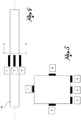
- reference numeral 1 globally denotes a fatigue test bench for manufactured items, in particular for manufactured items made from metallic material, specifically from aluminium and the alloys thereof.
- the bench 1 comprises a base 2 preferably made from a frame composed of girders, preferably welded to each other, to assure a high degree of rigidity.
- the bench 1 further comprises a table 4 for the support of the manufactured item to be tested, having its main extension along a table axis X.
- the bench 1 is further provided with means of constraint for the constraint and attachment if necessary of the manufactured item to the table.
- the means of constraint comprise a pair of blocks 6, for example distanced along the table axis 4, and respective cylinders 8, supported by the blocks 6, which the manufactured item W may be rested on.
- the configuration and the structure of the means of constraint varies according to the type of stress which the manufactured item is to be subjected to.
- the means of constraint formed by the two blocks 6 and the two cylinders 8 simulate a "joint" type constraint for the manufactured item.
- the bench 1 comprises in addition a frame 10 which surmounts the table 4 and is supported at the two sides of the table by the base 2.
- the frame 10 is also composed of a structure formed of girders, for example welded to each other.
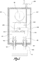
- the bench 1 comprises a drive group 20, at least partially supported by the frame 10, suitable for impressing upon the manufactured item W a variable stress over time by means of an imposed displacement.
- the drive group 20 comprises drive means, for example comprising an electric motor 22, for example supported by the frame 10.
- the group 20 further comprises a characterisation device 14, connected to the drive means, for example by means of a belt connection 24, and a pressure element 16, connected to the characterisation device, suitable for coming into contact with the manufactured item W to impose a deformation on it.
- the pressure element 16 is a plate, preferably reinforced and stiffened by ribs 16a, having a main extension along the table axis X, that is in the direction of extension of the manufactured item.
- such pressure element permits a distribution of the action on the manufactured item, so as to prevent concentrated actions which could lead to scoring of the manufactured item.
- the characterisation device 14 comprises a shaft 26 rotating by virtue of its connection to the drive means around a rotation axis Z fitted with at least one cam element 28, provided with an outer eccentric surface 28a, which operates the pressure element 16 impressing a vertical oscillation on it.
- At least two cam elements 28 are provided, distanced along the rotation axis Z of the shaft.
- the cam element 28 is made in one piece with the remaining part of the shaft 26.
- the shaft 26 also has support surfaces 30 and the device 14 comprises at least one bearing 32 for the support in rotation of the shaft, positioned at the support surfaces 30.
- the outer surfaces 28a of said cam elements 28 are lowered in relation to the support surfaces 30 of the bearings.
- the characterization device 14 further comprises transmission elements 40, firmly connected to the pressure element 16, each engaged and moved in oscillation by the relative cam element 28.
- said transmission elements 40 comprise rollers in contact with the respective cam elements, to improve the contact conditions with said cam elements.
- the characterisation device 14 is modifiable or replaceable to vary the characteristics of the deformation imposed on the manufactured item.
- a first shaft 26 is replaceable with a different shaft having differently shaped cam elements, so as to vary the characteristics of the displacement imposed on the pressure element and thus the characteristics of the deformation imposed on the manufactured item.
- the cam elements are replaceable.
- the transmission elements present cam-shaped contact surfaces with the shaft and are replaceable.
- the drive group 20 comprises return means, such as spiral springs 50 suitable for permanently pressing the pressure plate to ensure contact with the shaft 26.
- the drive group 20 further comprises a box 60, inside which the characterisation device 14 is housed, made so as to be oil or liquid proof.
- the characterisation device is in a bath of oil or of a coolant liquid, for adequate heat dissipation.
- the bench 1 comprises recirculation means operatively connected to the box 60 for the recirculation and the conditioning of the oil or of the coolant liquid.
- the bench 1 further comprises a derivation accessory, connectable to the pressure element, for the transformation of the vertical oscillatory movement of the same into a different desired movement (such as a horizontal oscillatory movement or circular oscillatory movement) or to apply the action to the manufactured item in a particular point in space, for example to adapt to the geometry of the manufactured item
- the bench 1 comprises a plurality of strain gauges, connectable to the manufactured product to detect the real deformation and stress, and a data management device, connected to said strain gauges, for the visualisation and management of the experimental data acquired.
- strain gauges In particular, the purpose of the strain gauges is to verify the real stress to which the manufactured item is subjected during the fatigue test. Moreover, the use of strain gauges, located in the areas subject to scoring or changes in cross-section, makes it possible to detect the real coefficient of overstress induced by the geometrical discontinuity.
- strain gauges are connected to the structure of the fatigue test bench 1, for example positioned on the columns of the frame 10 or base 2.
- accelerometers are provided to measure the vibrations acting on the manufactured item W or on the fatigue test bench 1.
- the manufactured item was tested with 12 Hz frequency up to 5*10 ⁇ 6 cycles Operating without stop times, the test lasts about 5 days.
- the displacement is imposed by a derivation accessory connected to the pressure plate for the simulation of the desired displacement.
- connection elements At an imposed frequency of 15 Hz, the test continues until failure of one of the connection elements (rivet or flap of sheet), reaching a duration limited to several days.
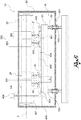
- strain gauges One example of application of strain gauges is shown in Figures 4 and 5 .
- the manufactured item is a prismatic extrudate, resting on two jointed supports, loaded on the centreline with an extensive load surface.
- the strain gauges 1 and 4 permit the detection of the maximum value of flexural stress (both of compression and of traction) and any asymmetries in the distribution of the stresses.
- strain gauges 2 and 6 placed on the neutral axis of the cross-section, permit assessment of any axial loads due to load or constraint imprecision (and permit, together with the values supplied by the strain gauges 1 and 4, an assessment of any stress asymmetries).
- strain gauges 3 and 5 permit assessment of any "corner stress” and the calculation of the consequent overstress coefficient, for example to determine the best connection radius between the edges as regards fatigue.
- the characterisation device 14 comprises a shaft 26 rotating around the rotation axis Z, fitted with at least one cam element 28 of a truncated cone shape, even with non-circular bases.
- the cam element 28 is provided with a smaller base bm and a larger base BM which respectively represent the minimum and maximum cam lift profile able to ensure contact with the transmission elements 40.
- the minimum cam lift profile is equal to 1 mm and the maximum cam lift profile is equal to 10 mm.
- each cam element 28 has a truncated cone shape defined, along the rotation axis Z, by:
- At least two cam elements 28 of a truncated-cone shape are provided, distanced along the rotation axis Z of the shaft.
- the characterisation device 14 comprises, for each cam element 28, a pair of transmission elements 40, firmly connected to the pressure element 16.
- Each transmission element 40 is translatable in the direction of the rotation axis Z, along the truncated cone profile of the cam element 28.
- a first transmission element 40 translatable along the profile of the first truncated cone cross-section 281, and a second transmission element 40 translatable along the profile of the second truncated cone cross-section 283 are provided.
- the first and the second transmission elements translate in opposite directions.
- Each transmission element 40 is therefore translatable between the first minimum lift profile and the maximum lift profile of each truncated cone cross-section. Such translation permits a precise adjustment of the displacement assigned to the pressure element 16 by acting on the position of the transmission elements 40.
- the characterisation device 14 is thus adjustable to vary the characteristics of the deformation imposed on the manufactured item W by means of the translation of the transmission element 40 along the truncated cone profile of the cam element 28'. This way, it is possible to vary the characteristics of the displacement imposed on the pressure element 16 without having to replace the shaft 26 with a different shaft having differently shaped cam elements.
- the transmission elements 40 comprise rollers 401 in contact with the respective cam elements 28.
- the rotation axis Z' of the rollers 401 is inclined in relation to the rotation axis Z of the shaft 26.
- the characterisation device 14 comprises for each truncated cone cam element 28, a pair of transmission elements 40 in the form of rollers 401 with rotation axes Z' inclined in relation to the rotation axis Z, according to the inclination of the respective truncated cone cross-section 281, 283.
- the presence of rollers 401 with inclined rotation axis Z' ensures contact between the cam element 28 and the transmission element 40, gradually as the latter is moved by translation in the direction of the rotation axis Z of the shaft 26 to perform an adjustment of the characterisation device 14.
- the translation of the transmission elements 40 along the guides 403 is performed by means of a control system comprising:
- control shaft 404 is provided with a mated threading (right hand and left-hand) for each pair of transmission elements 40.
- Each support 402 is coupled to the control shaft 403 by means of a threaded hole (lead screw) according to criteria typical of control screws.
- the rotation of the control shaft 404 permits each pair of supports 402 to reduce or increase the distance D between the transmission elements 40 so as to ensure the contact of the rollers 401 with the cam element 28 (and in particular with the respective truncated cone cross-section 281, 283) for each value chosen in the range comprised between the minimal lift profile and the maximum lift profile.
- the control shaft 404 is supported at the ends and in the centreline by supports 405 and is blocked in position by attachment elements, such as for example blocking rings , connected to said supports 405.
- the rotation of the control shaft 404 is controlled from outside the box using the handwheel 408, engaged on the vertical shaft 407 integral with the transmission mechanism 406.
- Such transmission mechanism 406, attached (for example by screws or welded,) to the upper plate 161 of the pressure element 16, comprises conical toothed wheels for the transmission of the movement between axes orthogonal to each other.
- the connection between these two shafts is made for example by means of a spanner screw type connection with recessed head upstream of the first support 405 at the end of the control shaft.
- the drive group 20 comprises return means, such as spiral springs 50 mounted for example along the columns 162 of the pressure element 16, suitable for permanently pressing the pressure plate to ensure contact with the shaft 26.
- return means such as spiral springs 50 mounted for example along the columns 162 of the pressure element 16, suitable for permanently pressing the pressure plate to ensure contact with the shaft 26.
- the pressure element 16 can thus translate vertically between the first minimum lift profile and the maximum lift profile of the truncated cone cam element 28, thus permitting the adjustment of the displacement imposed on the manufactured item W depending on the test in question.
- the possible vertical displacement of the pressure element 16 makes it necessary to correctly equilibrate the sum of the forces, (in particular the elastic reaction provided by the sample W subject to the imposed displacement, the forces of inertia of the oscillating masses, the elastic reaction provided by the spiral spring 50 at any moment of functioning, to ensure continuity of contact between the cam elements 28 and the respective rollers 401.
- the preloading of the spiral springs 50 is acted on.
- the pressure element 16 is then fitted with internally threaded sleeves 501, fitted along the columns 162, also threaded, of the pressure element 16.
- Each sleeve 501 can translate vertically along the columns 162 by screwing, by means of a connection typical of a ring nut
- the sleeve 501 is then fixed in the desired position by means of an attachment counter-nut 502.
- the variation of the preloading of the spiral spring 50 is then obtained by the vertical shifting of the sleeves 501, on the upper rim of which a lower end of said spring rests.
- the fatigue test bench according to the present invention makes it possible to perform experimental fatigue tests on real manufactured items, in a reasonable time and simulating real load conditions.
- the test bench makes it possible to modify the characteristics of the imposed displacement on the manufactured item according to the test to be performed or, for example, to simulate the real working conditions of the manufactured item.
- the test bench permits a considerable reduction of test times, even for tests performed for very high numbers of cycles, to the order of millions of cycles.
- the characterization device is adjustable to vary the characteristics of the deformation by means of the translation of the transmission element along the truncated cone profile of the cam element.
- the characterisation device is adjustable without the need to replace the shaft.
- the fatigue test bench proves more versatile and free of the need to build new shafts fitted with cam elements the profiles of which reproduce the different displacement, speed and acceleration values to impose at the physical point of the sample W tested each time
- the fatigue test bench permits a reduction of the costs and times for making new parts.
Landscapes
- Physics & Mathematics (AREA)
- Health & Medical Sciences (AREA)
- Life Sciences & Earth Sciences (AREA)
- Chemical & Material Sciences (AREA)
- Analytical Chemistry (AREA)
- Biochemistry (AREA)
- General Health & Medical Sciences (AREA)
- General Physics & Mathematics (AREA)
- Immunology (AREA)
- Pathology (AREA)
- Investigating Strength Of Materials By Application Of Mechanical Stress (AREA)
Applications Claiming Priority (2)
| Application Number | Priority Date | Filing Date | Title |
|---|---|---|---|
| IT000019A ITBS20120019A1 (it) | 2012-02-13 | 2012-02-13 | Banco di prova a fatica per manufatti |
| PCT/IB2013/051067 WO2013121333A1 (en) | 2012-02-13 | 2013-02-08 | Displacement-imposed fatigue test bench for a manufactured item |
Publications (2)
| Publication Number | Publication Date |
|---|---|
| EP2815225A1 EP2815225A1 (en) | 2014-12-24 |
| EP2815225B1 true EP2815225B1 (en) | 2019-11-20 |
Family
ID=45992711
Family Applications (1)
| Application Number | Title | Priority Date | Filing Date |
|---|---|---|---|
| EP13713238.7A Active EP2815225B1 (en) | 2012-02-13 | 2013-02-08 | Displacement-imposed fatigue test bench for a manufactured item |
Country Status (3)
| Country | Link |
|---|---|
| EP (1) | EP2815225B1 (it) |
| IT (1) | ITBS20120019A1 (it) |
| WO (1) | WO2013121333A1 (it) |
Cited By (2)
| Publication number | Priority date | Publication date | Assignee | Title |
|---|---|---|---|---|
| WO2025073069A1 (es) * | 2023-10-04 | 2025-04-10 | Universidad De Magallanes | Herramienta para torno universal que permite efectuar ensayo sobre una probeta |
| WO2025176870A1 (fr) * | 2024-02-23 | 2025-08-28 | Thales | Dispositif de simulation de déformation de coque |
Families Citing this family (6)
| Publication number | Priority date | Publication date | Assignee | Title |
|---|---|---|---|---|
| CN108132195B (zh) * | 2018-01-30 | 2024-03-29 | 湖南农业大学 | 可变支撑状态的苎麻茎杆收割刀具磨损试验台 |
| CN108426765B (zh) * | 2018-03-30 | 2024-04-26 | 西南交通大学 | 钢桥面板试件的疲劳试验装置 |
| CN109900597B (zh) * | 2019-03-04 | 2023-11-10 | 莆田学院 | 一种用于研究刀具粘结破损的扩散实验装置 |
| CN114778168B (zh) * | 2022-06-17 | 2022-09-02 | 中国飞机强度研究所 | 空天飞机舱段地面强度试验破坏载荷加载级数确定方法 |
| CN116337421B (zh) * | 2023-02-15 | 2026-04-03 | 江苏奔田机械科技有限公司 | 一种引导轮张紧机构的疲劳试验工装及其试验方法 |
| CN119000326B (zh) * | 2024-09-09 | 2025-03-28 | 金华九悦车业股份有限公司 | 一种运动滑板用强度检测装置 |
Citations (1)
| Publication number | Priority date | Publication date | Assignee | Title |
|---|---|---|---|---|
| US20070256503A1 (en) * | 2006-04-18 | 2007-11-08 | Agency For Science, Technology And Research | Bend testing apparatus and method of carrying out the same |
Family Cites Families (4)
| Publication number | Priority date | Publication date | Assignee | Title |
|---|---|---|---|---|
| FR2699279B1 (fr) * | 1992-12-11 | 1995-03-03 | Colas Sa | Appareil et procédé d'essai mécanique permettant d'étudier la fissuration en fatigue de matériaux routiers. |
| JP3723618B2 (ja) * | 1996-01-09 | 2005-12-07 | ソニー株式会社 | 試験装置および方法 |
| JP2001289762A (ja) * | 2000-04-05 | 2001-10-19 | Mitsubishi Heavy Ind Ltd | 輪荷重疲労試験機 |
| JP2006258454A (ja) * | 2005-03-15 | 2006-09-28 | Toray Ind Inc | 軽量サンドイッチパネルの曲げ疲労試験方法 |
-
2012
- 2012-02-13 IT IT000019A patent/ITBS20120019A1/it unknown
-
2013
- 2013-02-08 EP EP13713238.7A patent/EP2815225B1/en active Active
- 2013-02-08 WO PCT/IB2013/051067 patent/WO2013121333A1/en not_active Ceased
Patent Citations (1)
| Publication number | Priority date | Publication date | Assignee | Title |
|---|---|---|---|---|
| US20070256503A1 (en) * | 2006-04-18 | 2007-11-08 | Agency For Science, Technology And Research | Bend testing apparatus and method of carrying out the same |
Cited By (3)
| Publication number | Priority date | Publication date | Assignee | Title |
|---|---|---|---|---|
| WO2025073069A1 (es) * | 2023-10-04 | 2025-04-10 | Universidad De Magallanes | Herramienta para torno universal que permite efectuar ensayo sobre una probeta |
| WO2025176870A1 (fr) * | 2024-02-23 | 2025-08-28 | Thales | Dispositif de simulation de déformation de coque |
| FR3159587A1 (fr) * | 2024-02-23 | 2025-08-29 | Thales | Dispositif de simulation de déformation de coque. |
Also Published As
| Publication number | Publication date |
|---|---|
| EP2815225A1 (en) | 2014-12-24 |
| ITBS20120019A1 (it) | 2013-08-14 |
| WO2013121333A1 (en) | 2013-08-22 |
Similar Documents
| Publication | Publication Date | Title |
|---|---|---|
| EP2815225B1 (en) | Displacement-imposed fatigue test bench for a manufactured item | |
| JP6772679B2 (ja) | 疲労試験装置及び疲労試験方法 | |
| CN206192652U (zh) | 行星滚柱丝杠副的双向加载装置 | |
| EP2789410A1 (en) | Curvature retaining device for plate-shaped workpiece, curvature retaining method for plate-shaped workpiece, and curvature forming method for plate-shaped workpiece | |
| CA2912741C (en) | Apparatus and method for performing multiple discrete point pressing, twisting, retaining and shaping of plate-workpieces | |
| JP5930103B2 (ja) | 加圧式歪取装置 | |
| US20090071261A1 (en) | Mill Configured for a Thermo-mechanical Simulating Test System | |
| CN106890871B (zh) | 机架变形补偿装置及折弯机 | |
| DE102014106262B4 (de) | Detektiervorrichtung für lagerbuchsen-kraftkomponenten | |
| RU2401241C2 (ru) | Устройство стропления детали с компенсацией усилия и подъемная система с таким устройством | |
| DE102014106256B4 (de) | Detektiervorrichtung für lagerbuchsen-kraftkomponenten | |
| CN107101902A (zh) | 一种微动摩擦试验机 | |
| KR20100125429A (ko) | 성형 롤러가 구비된 원형 압연기 | |
| CN214200923U (zh) | 高温弯曲疲劳原位测试装置 | |
| US11249007B2 (en) | Universal strip tribological simulator | |
| CN106442148A (zh) | 一种用于链条销轴的脆性检测仪 | |
| JP6299633B2 (ja) | 軸心調整装置および材料試験機 | |
| US10520386B2 (en) | Vibration measurement device and method for high-speed rotating machines | |
| CN110153973A (zh) | 一种汽车动力总成用三轴六向可调工装 | |
| CN106768539A (zh) | 行星滚柱丝杠副的双向加载装置与加载方法 | |
| CN205910083U (zh) | 一种冲滑复合摩擦磨损试验装置 | |
| CN104458257B (zh) | 针对转轴的支反力模拟装置 | |
| CN105618382B (zh) | 一种弯钢阻挡器 | |
| CN101137942B (zh) | 用于确定构件的弹性形变的方法 | |
| CN102661831A (zh) | 换向装置、减震器示功机拉向力值校准装置及校准方法 |
Legal Events
| Date | Code | Title | Description |
|---|---|---|---|
| PUAI | Public reference made under article 153(3) epc to a published international application that has entered the european phase |
Free format text: ORIGINAL CODE: 0009012 |
|
| 17P | Request for examination filed |
Effective date: 20140805 |
|
| AK | Designated contracting states |
Kind code of ref document: A1 Designated state(s): AL AT BE BG CH CY CZ DE DK EE ES FI FR GB GR HR HU IE IS IT LI LT LU LV MC MK MT NL NO PL PT RO RS SE SI SK SM TR |
|
| AX | Request for extension of the european patent |
Extension state: BA ME |
|
| DAX | Request for extension of the european patent (deleted) | ||
| STAA | Information on the status of an ep patent application or granted ep patent |
Free format text: STATUS: EXAMINATION IS IN PROGRESS |
|
| 17Q | First examination report despatched |
Effective date: 20181218 |
|
| GRAP | Despatch of communication of intention to grant a patent |
Free format text: ORIGINAL CODE: EPIDOSNIGR1 |
|
| STAA | Information on the status of an ep patent application or granted ep patent |
Free format text: STATUS: GRANT OF PATENT IS INTENDED |
|
| INTG | Intention to grant announced |
Effective date: 20190626 |
|
| GRAS | Grant fee paid |
Free format text: ORIGINAL CODE: EPIDOSNIGR3 |
|
| GRAA | (expected) grant |
Free format text: ORIGINAL CODE: 0009210 |
|
| STAA | Information on the status of an ep patent application or granted ep patent |
Free format text: STATUS: THE PATENT HAS BEEN GRANTED |
|
| AK | Designated contracting states |
Kind code of ref document: B1 Designated state(s): AL AT BE BG CH CY CZ DE DK EE ES FI FR GB GR HR HU IE IS IT LI LT LU LV MC MK MT NL NO PL PT RO RS SE SI SK SM TR |
|
| REG | Reference to a national code |
Ref country code: GB Ref legal event code: FG4D |
|
| REG | Reference to a national code |
Ref country code: CH Ref legal event code: EP |
|
| REG | Reference to a national code |
Ref country code: IE Ref legal event code: FG4D |
|
| REG | Reference to a national code |
Ref country code: DE Ref legal event code: R096 Ref document number: 602013063074 Country of ref document: DE |
|
| REG | Reference to a national code |
Ref country code: AT Ref legal event code: REF Ref document number: 1204729 Country of ref document: AT Kind code of ref document: T Effective date: 20191215 |
|
| REG | Reference to a national code |
Ref country code: NL Ref legal event code: MP Effective date: 20191120 |
|
| REG | Reference to a national code |
Ref country code: LT Ref legal event code: MG4D |
|
| PG25 | Lapsed in a contracting state [announced via postgrant information from national office to epo] |
Ref country code: ES Free format text: LAPSE BECAUSE OF FAILURE TO SUBMIT A TRANSLATION OF THE DESCRIPTION OR TO PAY THE FEE WITHIN THE PRESCRIBED TIME-LIMIT Effective date: 20191120 Ref country code: LV Free format text: LAPSE BECAUSE OF FAILURE TO SUBMIT A TRANSLATION OF THE DESCRIPTION OR TO PAY THE FEE WITHIN THE PRESCRIBED TIME-LIMIT Effective date: 20191120 Ref country code: GR Free format text: LAPSE BECAUSE OF FAILURE TO SUBMIT A TRANSLATION OF THE DESCRIPTION OR TO PAY THE FEE WITHIN THE PRESCRIBED TIME-LIMIT Effective date: 20200221 Ref country code: NO Free format text: LAPSE BECAUSE OF FAILURE TO SUBMIT A TRANSLATION OF THE DESCRIPTION OR TO PAY THE FEE WITHIN THE PRESCRIBED TIME-LIMIT Effective date: 20200220 Ref country code: SE Free format text: LAPSE BECAUSE OF FAILURE TO SUBMIT A TRANSLATION OF THE DESCRIPTION OR TO PAY THE FEE WITHIN THE PRESCRIBED TIME-LIMIT Effective date: 20191120 Ref country code: NL Free format text: LAPSE BECAUSE OF FAILURE TO SUBMIT A TRANSLATION OF THE DESCRIPTION OR TO PAY THE FEE WITHIN THE PRESCRIBED TIME-LIMIT Effective date: 20191120 Ref country code: BG Free format text: LAPSE BECAUSE OF FAILURE TO SUBMIT A TRANSLATION OF THE DESCRIPTION OR TO PAY THE FEE WITHIN THE PRESCRIBED TIME-LIMIT Effective date: 20200220 Ref country code: LT Free format text: LAPSE BECAUSE OF FAILURE TO SUBMIT A TRANSLATION OF THE DESCRIPTION OR TO PAY THE FEE WITHIN THE PRESCRIBED TIME-LIMIT Effective date: 20191120 Ref country code: FI Free format text: LAPSE BECAUSE OF FAILURE TO SUBMIT A TRANSLATION OF THE DESCRIPTION OR TO PAY THE FEE WITHIN THE PRESCRIBED TIME-LIMIT Effective date: 20191120 |
|
| PG25 | Lapsed in a contracting state [announced via postgrant information from national office to epo] |
Ref country code: RS Free format text: LAPSE BECAUSE OF FAILURE TO SUBMIT A TRANSLATION OF THE DESCRIPTION OR TO PAY THE FEE WITHIN THE PRESCRIBED TIME-LIMIT Effective date: 20191120 Ref country code: IS Free format text: LAPSE BECAUSE OF FAILURE TO SUBMIT A TRANSLATION OF THE DESCRIPTION OR TO PAY THE FEE WITHIN THE PRESCRIBED TIME-LIMIT Effective date: 20200320 Ref country code: HR Free format text: LAPSE BECAUSE OF FAILURE TO SUBMIT A TRANSLATION OF THE DESCRIPTION OR TO PAY THE FEE WITHIN THE PRESCRIBED TIME-LIMIT Effective date: 20191120 |
|
| PG25 | Lapsed in a contracting state [announced via postgrant information from national office to epo] |
Ref country code: AL Free format text: LAPSE BECAUSE OF FAILURE TO SUBMIT A TRANSLATION OF THE DESCRIPTION OR TO PAY THE FEE WITHIN THE PRESCRIBED TIME-LIMIT Effective date: 20191120 |
|
| PG25 | Lapsed in a contracting state [announced via postgrant information from national office to epo] |
Ref country code: EE Free format text: LAPSE BECAUSE OF FAILURE TO SUBMIT A TRANSLATION OF THE DESCRIPTION OR TO PAY THE FEE WITHIN THE PRESCRIBED TIME-LIMIT Effective date: 20191120 Ref country code: PT Free format text: LAPSE BECAUSE OF FAILURE TO SUBMIT A TRANSLATION OF THE DESCRIPTION OR TO PAY THE FEE WITHIN THE PRESCRIBED TIME-LIMIT Effective date: 20200412 Ref country code: DK Free format text: LAPSE BECAUSE OF FAILURE TO SUBMIT A TRANSLATION OF THE DESCRIPTION OR TO PAY THE FEE WITHIN THE PRESCRIBED TIME-LIMIT Effective date: 20191120 Ref country code: CZ Free format text: LAPSE BECAUSE OF FAILURE TO SUBMIT A TRANSLATION OF THE DESCRIPTION OR TO PAY THE FEE WITHIN THE PRESCRIBED TIME-LIMIT Effective date: 20191120 Ref country code: RO Free format text: LAPSE BECAUSE OF FAILURE TO SUBMIT A TRANSLATION OF THE DESCRIPTION OR TO PAY THE FEE WITHIN THE PRESCRIBED TIME-LIMIT Effective date: 20191120 |
|
| REG | Reference to a national code |
Ref country code: AT Ref legal event code: MK05 Ref document number: 1204729 Country of ref document: AT Kind code of ref document: T Effective date: 20191120 |
|
| REG | Reference to a national code |
Ref country code: DE Ref legal event code: R097 Ref document number: 602013063074 Country of ref document: DE |
|
| PG25 | Lapsed in a contracting state [announced via postgrant information from national office to epo] |
Ref country code: SM Free format text: LAPSE BECAUSE OF FAILURE TO SUBMIT A TRANSLATION OF THE DESCRIPTION OR TO PAY THE FEE WITHIN THE PRESCRIBED TIME-LIMIT Effective date: 20191120 Ref country code: SK Free format text: LAPSE BECAUSE OF FAILURE TO SUBMIT A TRANSLATION OF THE DESCRIPTION OR TO PAY THE FEE WITHIN THE PRESCRIBED TIME-LIMIT Effective date: 20191120 |
|
| REG | Reference to a national code |
Ref country code: DE Ref legal event code: R119 Ref document number: 602013063074 Country of ref document: DE |
|
| PLBE | No opposition filed within time limit |
Free format text: ORIGINAL CODE: 0009261 |
|
| STAA | Information on the status of an ep patent application or granted ep patent |
Free format text: STATUS: NO OPPOSITION FILED WITHIN TIME LIMIT |
|
| REG | Reference to a national code |
Ref country code: CH Ref legal event code: PL |
|
| 26N | No opposition filed |
Effective date: 20200821 |
|
| GBPC | Gb: european patent ceased through non-payment of renewal fee |
Effective date: 20200220 |
|
| REG | Reference to a national code |
Ref country code: BE Ref legal event code: MM Effective date: 20200229 |
|
| PG25 | Lapsed in a contracting state [announced via postgrant information from national office to epo] |
Ref country code: MC Free format text: LAPSE BECAUSE OF FAILURE TO SUBMIT A TRANSLATION OF THE DESCRIPTION OR TO PAY THE FEE WITHIN THE PRESCRIBED TIME-LIMIT Effective date: 20191120 Ref country code: LU Free format text: LAPSE BECAUSE OF NON-PAYMENT OF DUE FEES Effective date: 20200208 |
|
| PG25 | Lapsed in a contracting state [announced via postgrant information from national office to epo] |
Ref country code: LI Free format text: LAPSE BECAUSE OF NON-PAYMENT OF DUE FEES Effective date: 20200229 Ref country code: CH Free format text: LAPSE BECAUSE OF NON-PAYMENT OF DUE FEES Effective date: 20200229 Ref country code: AT Free format text: LAPSE BECAUSE OF FAILURE TO SUBMIT A TRANSLATION OF THE DESCRIPTION OR TO PAY THE FEE WITHIN THE PRESCRIBED TIME-LIMIT Effective date: 20191120 Ref country code: PL Free format text: LAPSE BECAUSE OF FAILURE TO SUBMIT A TRANSLATION OF THE DESCRIPTION OR TO PAY THE FEE WITHIN THE PRESCRIBED TIME-LIMIT Effective date: 20191120 Ref country code: SI Free format text: LAPSE BECAUSE OF FAILURE TO SUBMIT A TRANSLATION OF THE DESCRIPTION OR TO PAY THE FEE WITHIN THE PRESCRIBED TIME-LIMIT Effective date: 20191120 |
|
| PG25 | Lapsed in a contracting state [announced via postgrant information from national office to epo] |
Ref country code: IE Free format text: LAPSE BECAUSE OF NON-PAYMENT OF DUE FEES Effective date: 20200208 Ref country code: GB Free format text: LAPSE BECAUSE OF NON-PAYMENT OF DUE FEES Effective date: 20200220 Ref country code: FR Free format text: LAPSE BECAUSE OF NON-PAYMENT OF DUE FEES Effective date: 20200229 Ref country code: DE Free format text: LAPSE BECAUSE OF NON-PAYMENT OF DUE FEES Effective date: 20200901 |
|
| PG25 | Lapsed in a contracting state [announced via postgrant information from national office to epo] |
Ref country code: BE Free format text: LAPSE BECAUSE OF NON-PAYMENT OF DUE FEES Effective date: 20200229 |
|
| PG25 | Lapsed in a contracting state [announced via postgrant information from national office to epo] |
Ref country code: TR Free format text: LAPSE BECAUSE OF FAILURE TO SUBMIT A TRANSLATION OF THE DESCRIPTION OR TO PAY THE FEE WITHIN THE PRESCRIBED TIME-LIMIT Effective date: 20191120 Ref country code: MT Free format text: LAPSE BECAUSE OF FAILURE TO SUBMIT A TRANSLATION OF THE DESCRIPTION OR TO PAY THE FEE WITHIN THE PRESCRIBED TIME-LIMIT Effective date: 20191120 Ref country code: CY Free format text: LAPSE BECAUSE OF FAILURE TO SUBMIT A TRANSLATION OF THE DESCRIPTION OR TO PAY THE FEE WITHIN THE PRESCRIBED TIME-LIMIT Effective date: 20191120 |
|
| PG25 | Lapsed in a contracting state [announced via postgrant information from national office to epo] |
Ref country code: MK Free format text: LAPSE BECAUSE OF FAILURE TO SUBMIT A TRANSLATION OF THE DESCRIPTION OR TO PAY THE FEE WITHIN THE PRESCRIBED TIME-LIMIT Effective date: 20191120 |
|
| PGFP | Annual fee paid to national office [announced via postgrant information from national office to epo] |
Ref country code: IT Payment date: 20251222 Year of fee payment: 14 |