EP2815486B1 - Statoranordnung und elektrische maschine - Google Patents
Statoranordnung und elektrische maschine Download PDFInfo
- Publication number
- EP2815486B1 EP2815486B1 EP13734958.5A EP13734958A EP2815486B1 EP 2815486 B1 EP2815486 B1 EP 2815486B1 EP 13734958 A EP13734958 A EP 13734958A EP 2815486 B1 EP2815486 B1 EP 2815486B1
- Authority
- EP
- European Patent Office
- Prior art keywords
- stator
- winding
- contact conductor
- hook
- stator arrangement
- Prior art date
- Legal status (The legal status is an assumption and is not a legal conclusion. Google has not performed a legal analysis and makes no representation as to the accuracy of the status listed.)
- Active
Links
Images


Classifications
-
- H—ELECTRICITY
- H02—GENERATION; CONVERSION OR DISTRIBUTION OF ELECTRIC POWER
- H02K—DYNAMO-ELECTRIC MACHINES
- H02K3/00—Details of windings
- H02K3/46—Fastening of windings on the stator or rotor structure
- H02K3/52—Fastening salient pole windings or connections thereto
- H02K3/521—Fastening salient pole windings or connections thereto applicable to stators only
- H02K3/522—Fastening salient pole windings or connections thereto applicable to stators only for generally annular cores with salient poles
-
- H—ELECTRICITY
- H02—GENERATION; CONVERSION OR DISTRIBUTION OF ELECTRIC POWER
- H02K—DYNAMO-ELECTRIC MACHINES
- H02K3/00—Details of windings
- H02K3/04—Windings characterised by the conductor shape, form or construction, e.g. with bar conductors
- H02K3/28—Layout of windings or of connections between windings
-
- H—ELECTRICITY
- H02—GENERATION; CONVERSION OR DISTRIBUTION OF ELECTRIC POWER
- H02K—DYNAMO-ELECTRIC MACHINES
- H02K1/00—Details of the magnetic circuit
- H02K1/06—Details of the magnetic circuit characterised by the shape, form or construction
- H02K1/12—Stationary parts of the magnetic circuit
-
- H—ELECTRICITY
- H02—GENERATION; CONVERSION OR DISTRIBUTION OF ELECTRIC POWER
- H02K—DYNAMO-ELECTRIC MACHINES
- H02K1/00—Details of the magnetic circuit
- H02K1/06—Details of the magnetic circuit characterised by the shape, form or construction
- H02K1/12—Stationary parts of the magnetic circuit
- H02K1/17—Stator cores with permanent magnets
-
- H—ELECTRICITY
- H02—GENERATION; CONVERSION OR DISTRIBUTION OF ELECTRIC POWER
- H02K—DYNAMO-ELECTRIC MACHINES
- H02K2203/00—Specific aspects not provided for in the other groups of this subclass relating to the windings
- H02K2203/09—Machines characterised by wiring elements other than wires, e.g. bus rings, for connecting the winding terminations
Definitions
- the present invention relates to a stator arrangement and an electrical machine, in particular for the automotive sector.
- Electric machines e.g. B. electric motors are used in the automotive sector for a wide variety of purposes and applications. For example, electric motors are used to drive radiator fan modules. Furthermore, electric motors are also used as a drive for the operation of window regulators, belt tensioners, seat adjusters, exterior mirrors, electric parking brakes, transmission actuators, oil pumps, for coupling and shifting in a double clutch transmission and the like.
- Such electric motors generally have a stator and a rotor rotatably mounted in the stator.
- the stator usually has a stator core which forms a multiplicity of stator teeth, around which stator windings are wound in a known manner. When the current flows through the winding wire, the stator windings wound around the stator teeth generate an electromagnetic field which, in cooperation with the rotor, causes the rotor to rotate.
- stator windings there are currently a number of options for connecting the stator windings to contact connections, which then be electrically connected to a connection socket or a corresponding contacting device.
- contacting the winding wire of the stator winding with a large number of individual contacts is very difficult and time-consuming.
- the individual contacts must be fixed in an insulating disc or pockets before winding.
- a respective wire must be guided into a defined position in the vicinity or to the individual contacts in order to then connect them to one another electrically and mechanically.
- the US 2005 088049 A describes a stator for an electric motor, which has an annular stator lamination stack.
- An annular connection unit is provided on an end face of the stator package.
- the connecting device has a support structure in which recesses are formed. Electrically insulated connecting rings which connect individual stator teeth to one another are provided in these recesses.
- the WO 2011/108735 A1 describes a stator which is formed from stator segments and a motor.
- the stator has contact conductors which have curved sections.
- the DE 10 2010 033 699 A1 describes a switch head for electric motors, with a winding and contact pieces, which are electrically conductively connected to connecting wires of the winding, and with contacts for connecting leads, the contacts being part of contact rings and being insertable into the contact pieces in the manner of a bayonet lock.
- the idea underlying the present invention is, instead of connecting each stator winding with a wire and connecting the ends of the wire winding with individual contacts, to use continuous contact conductors, which each connect a plurality of stator windings to one another.
- These contact conductors have connection lugs for the electrical contacting of a connection unit and hooks to accommodate the ends of the wire winding (stator winding) in order to produce an electrical contact.
- the stator winding can be contacted in a very simple manner. This also results in a significantly simplified winding scheme for the entire stator, since the winding wires no longer have to be laid on one of the end faces of the stator in a complicated, time-consuming and space-consuming manner.
- the stator arrangement according to the invention can be used in different types of electrical machines, for example in generators and motors.
- the hook is formed by folding the material of the contact conductor twice.
- the contact conductor material is first folded a first time in order to double the thickness of the contact conductor.
- the contact conductor material is then folded a second time to form the contour of a hook.
- the hook is stable enough to be welded to the wire of the stator winding.
- Another advantage is that the end of a winding wire can also be particularly securely clamped in the hook.
- a respective winding wire end is non-positively clamped or inserted into a hook assigned to the winding wire end.
- the positive connection is particularly simple since no additional work steps are required to connect the wire winding end to the contact conductor.
- the wire When winding on the stator teeth or the tooth insulation sections, the wire should be guided as horizontally as possible through the cutouts and the hooks, which makes it unlikely to slip. In addition, the hook is not axially bent by the tension of the wire in a horizontal position.
- the friction caused by the pinching of the wire winding end in the hook is sufficient to fix the winding wire end securely in the hook.
- the stiffness of the Hook larger or smaller can be selected.
- a positive and / or material connection between the end of the winding wire and the hook can additionally or alternatively also be provided.
- the end of the winding wire is hot-calked with the hook. This creates a cohesive connection between the winding wire end and the hook.
- the hooks only serve as a positioning aid for the later hot caulking process.
- Other options for fixing the end of the winding wire with the hook such as riveting, gluing, welding, soldering, etc., are of course also possible and advantageous. In this way, a gastight electrical connection between the winding wire end and the hook can be formed.
- the contact conductor has at least two hooks and preferably exactly two hooks, preferably at opposite ends of the respective contact conductor. This configuration makes it possible in a simple manner to electrically connect a plurality of winding wire ends to the contact conductor. In this way, the manufacturing costs can also be reduced.
- the hook is preferably formed in one piece or in one piece on the terminal lug of the contact conductor. In this way, the efficiency of the stator can be increased since the resistance is particularly low due to the small distance between the connecting lug and the end of the winding wire. Also the mechanical stability is increased and the hook cannot be easily torn off.
- the contacting device has a carrier part for receiving the contact conductors, which is formed from a plastic.
- the carrier part is preferably formed from a glass fiber reinforced plastic, for example from PA 6.6 GF30.
- the carrier part serves the purpose of preferably receiving, holding and fixing the contact conductors in a form-fitting manner.
- the connection lugs are aligned by the carrier part.
- the contact conductor is made from a sheet, preferably from a stamped sheet.
- sheet metal is understood to be a metal which has a thickness of less than 5 mm, preferably less than 3 mm, and is electrically conductive.
- a steel alloy or an aluminum alloy can be used as the sheet metal material.
- the contact conductors are preferably punched out of the sheet metal material or cut out of the sheet metal material by means of a laser device. Water jet abrasive cutting is also possible. The production costs of the stator arrangement of the electrical machine can be significantly reduced by forming the contact conductors from a sheet metal.
- the contact conductor is made of bronze.
- the Contact conductor made of CuSn6.
- the contact conductor is additionally silver-plated, for example with a 1-3 ⁇ m thick silver-plating layer, which can be applied to the contact conductor, for example by electroplating. It is also possible to nickel the contact conductor. For example, 2-3 ⁇ m sub-nickel can be used for the contact conductor. In this way, the corrosion resistance of the contact conductor is increased. The service life of the stator arrangement can thereby be increased.
- Other electrically conductive materials for the formation of the contact conductor are of course also possible.
- the contact conductor can also be formed from a copper alloy or an iron alloy.
- the stator laminated core forms a multiplicity of stator teeth on which a multiplicity of stator windings is provided.
- the stator teeth have grooves in the winding direction of the respective winding wire, which prevent the stator winding from slipping off the respective stator tooth.
- the contacting device has tooth insulation sections which form the upper quarter or the upper half of the stator tooth.
- the upper quarter of the stator tooth is semicircular. In one embodiment, this upper quarter is provided with grooves which are formed at regular intervals in the radial direction on the stator tooth section of the contacting device.
- an insulating washer is provided on the opposite side of the stator laminated core, which likewise has tooth-insulating sections which form the lower quarter or the lower half of a stator tooth.
- the tooth insulating sections of the insulating end plate can also be in one Embodiment may be provided with grooves between which the stator winding is received. When the stator winding is wound, the wire is now held in a form-fitting manner between the grooves, so that the stator winding is prevented from slipping off the stator tooth during winding. In this way, errors in the manufacture of the stator are avoided, so that a low scrap is produced.
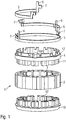
- Fig. 1 shows an exploded perspective view of a stator arrangement 1.
- the stator arrangement 1 is designed for an electrical machine, for example an electrical three-phase motor or an electrical three-phase generator.
- the stator arrangement 1 has a stator laminated core 2 which has a multiplicity of stator teeth 3.
- the stator laminated core 2 is formed from a large number of stamped laminations which are electrically and mechanically connected to one another. Other configurations of a stator, for example a one-piece design, are of course also possible.
- stator teeth 3 of the stator laminated core 2 serve to accommodate a stator winding.
- the stator windings are wound around the stator teeth 3.
- a contacting device 4 is shown above the stator laminated core 2.
- the contacting device 4 is formed, for example, from a plastic.
- the contacting device 4 has toothed insulation sections 12 which can be connected in a positive and non-positive manner to corresponding recesses in the stator laminated core 2.
- the contacting device 4 has a plurality of recesses 13, which are designed to receive the contact conductors 5.
- the contact conductors 5 are shown above the contacting device 4. In this embodiment, three contact conductors 5 are received by the receptacle 13 of the contacting device 4.
- the contact conductors 5 are formed, for example, from a metal alloy.
- the contact conductors 5 are formed from a bronze alloy.
- the contact conductors 5 have a semicircular shape.
- the contact conductors 5 each have connection lugs 6, which are designed to make contact with an external connection unit (not shown here).
- the connection lugs 6 extend in the axial direction of the stator arrangement 1.
- the contact conductors 5 have hooks 7, in which the winding wire ends 14 of the stator windings 9 can be inserted and / or clamped.
- the hooks 7 are preferably formed on the terminal lugs 6 of the contact conductors 5 and protrude from them.
- each contact conductor 5 has two hooks 7 on.
- the hooks 7 are arranged laterally on the contact conductors 5 and extend in the radial direction.
- an insulating washer 10 is shown below the stator laminated core 2, which forms the lower end of the stator arrangement 1.
- the insulating end plate 10 has tooth insulation sections 11, which cover and electrically insulate a lower part of the stator teeth, and around which the stator winding is wound.
- three contact conductors 5 are shown. It is of course possible for more than three or fewer than three contact conductors 5 to be used, depending on the field of application and embodiment of the electrical machine or the stator arrangement 1.
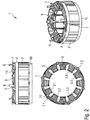
- Fig. 2 shows different views of the stator arrangement 1 with stator windings 9 Fig. 2 a side view of the stator arrangement 2 is shown. A top view of the stator arrangement 1 is shown at the bottom left. A perspective view of the stator arrangement 1 is shown at the bottom right.
- the stator teeth 3 of the stator core 2 are provided with stator windings 9.
- a one-piece wire is used for the stator windings 9 of the stator teeth 3.1 and 3.2.
- the winding end 14 of the stator winding 9 is clamped in the hook 7.1 of a contact conductor 5.
- the stator winding 9 of the stator teeth 3.3 and 3.4 is also formed from a one-piece wire. The end of these stator windings 9 is clamped in the hook 7.2 of the contact conductor 5.
- the stator windings 9 of the stator teeth 3.1, 3.2, 3.3 and 3.4 electrically coupled together.
- stator windings 9 This results in a very simple connection of the stator windings 9 without stator windings 9 which have been crossed over several times. In this way, the stator windings 9 can be wound very easily around the stator teeth 3. A complicated laying of the winding wire ends 14 is not necessary. This configuration is particularly suitable for needle windings.
- the contact conductors 5 can have more than two hooks 7.1, 7.2.
- a contact conductor 5 could be designed such that it electrically couples the stator windings 9 of the stator teeth 3.1, 3.3 and 3.5 to one another.
- the number of connecting lugs 6 can also be adapted to the respective field of application or the particular design of the electrical machine.
- Fig. 3 shows different views of the stator arrangement 1 without the stator winding 9
- Fig. 3 is a Side view of the stator assembly 1 shown.
- a top view of the stator arrangement 1 is shown at the bottom left.
- a perspective view of the stator arrangement 1 is shown at the bottom right.
- semicircular sections 11 are provided on the contacting device 4.
- the semicircular tooth insulating sections 11 form the upper section of a stator tooth 3 and electrically isolate it.
- - semicircular tooth insulation sections 12 are formed, which form the lower section of a stator tooth 3 and electrically insulate it. Due to the semicircular design of the tooth insulation sections 11 and 12, the winding can be done very easily.
- a series of grooves 15 can be provided on both sides, by means of which the stator winding 9 can be fixed during winding onto the stator teeth 3. This prevents the stator winding 9 from slipping from the stator tooth 3 during the winding of the stator winding 9.
- Fig. 4 represents a contact conductor 5.
- the contact conductor 5 is punched out of sheet metal, for example, and then in a further process step into the desired shape, which is shown in FIG Fig. 4 is shown, reshaped.
- the contact conductor 5 has a first middle section 5.1 and a second middle section 5.2, which adjoin one another at a bend 17.
- the two central sections 5.1, 5.2 are radially offset from one another by the bend 17.
- the kink 17 serves to create space for a further contact conductor 5.
- the contact conductors 5 in one plane in the recesses 13 of the Contacting device 4 added.
- the kink 17 makes it possible for the contact conductors 5 to be arranged in one plane.
- a connecting lug 6 is formed at one end 18 of the contact conductor 5.
- the connection lug 6 serves for the electrical contacting of an external connection unit, which supplies the stator with electrical energy or extracts electrical energy from the stator by the electric motor operated as a generator.
- a hook 7 is provided on the side of the connecting lug 6.
- the hook 7 is formed by folding the contact conductor material twice. The first fold serves to increase the thickness of the contact conductor material and the second fold serves to shape the hook 7. In this way, the thickness of the hook 7 is increased so that it is suitable for being connected to the winding end 14 of the stator winding 9 by welding ,
- a second hook 7 is provided at the opposite end 19 of the contact conductor 5. This hook 7 also serves to receive a corresponding winding wire end 14.
- the contact conductor 5 in Fig. 4 two hooks 7 and a bend 17 are provided.
- the contact conductor 5 it is possible for the contact conductor 5 to have only one hook 7 and no kink 17. Furthermore, it is also possible for the contact conductor 5 to have more than two hooks and more than one kink 17. Depending on the field of application and design of the electrical machine, the number of hooks 7 and the number of kinks 17 can be adapted.
Landscapes
- Engineering & Computer Science (AREA)
- Power Engineering (AREA)
- Insulation, Fastening Of Motor, Generator Windings (AREA)
- Manufacture Of Motors, Generators (AREA)
- Windings For Motors And Generators (AREA)
Description
- Die vorliegende Erfindung betrifft eine Statoranordnung und eine elektrische Maschine, insbesondere für den Automobilbereich.
- Elektrische Maschinen, z. B. Elektromotoren, werden im Automobilbereich für die unterschiedlichsten Zwecke und Anwendungen eingesetzt. Beispielsweise werden Elektromotoren zum Antreiben von Kühlerlüftermodulen verwendet. Ferner werden Elektromotoren auch als Antrieb für den Betrieb von Fensterhebern, Gurtstraffern, Sitzverstellungen, Außenspiegeln, elektrische Feststellbremsen, Getriebe-Aktuatoriken, Ölpumpen, zum Kuppeln und Schalten in einen Doppelkupplungsgetriebe und dergleichen eingesetzt.
- Solche Elektromotoren weisen im Allgemeinen einen Stator und einen im Stator drehbar gelagerten Rotor auf. Der Stator weist üblicherweise einen Statorkern auf, welcher eine Vielzahl von Statorzähnen ausbildet, um welche in bekannter Weise Statorwicklungen gewickelt sind. Die um die Statorzähne gewickelten Statorwicklungen erzeugen bei einem Stromfluss durch den Wicklungsdraht ein elektromagnetisches Feld, welches in Zusammenwirken mit dem Rotor diesen in Drehbewegen versetzt.
- Aktuell existiert eine Vielzahl von Möglichkeiten, die Statorwicklungen mit Kontaktanschlüssen zu verbinden, die dann elektrisch mit einer Anschlussbuchse bzw. einer entsprechenden Kontaktiereinrichtung verbunden werden. Die Kontaktierung des Wicklungsdrahtes der Statorwicklung mit einer Vielzahl von Einzelkontakten gestaltet sich indes sehr schwierig und aufwändig. Die Einzelkontakte müssen hierzu vor dem Wickeln in einer Isolierendscheibe oder Taschen fixiert werden. Während des Wickelvorganges, beispielsweise mittels einer Nadelwicklung bzw. eines Flyers, muss ein jeweiliger Draht in eine definierte Position in die Nähe oder an die Einzelkontakte geführt werden, um diese dann elektrisch und mechanisch miteinander zu verbinden. Ferner ist es bisweilen erforderlich, dass mehrere Statorwicklungen auf den Statorzähnen miteinander verbunden werden. Diese Verbindung geschieht üblicherweise über den Draht der einzelnen Statorwicklungen und birgt daher Nachteile einer komplizierten Verlegung von einem Statorzahn zum einem zu verbindenden benachbarten Statorzahn.
- Die
US 2005 088049 A beschreibt einen Stator für einen elektrischen Motor, der ein ringförmiges Statorblechpaket aufweist. Eine ringförmige Verbindungseinheit ist auf einer Stirnseite des Statorpakets vorgesehen. Die Verbindungseinrichtung weist eine Tragestruktur auf, in welcher Ausnehmungen ausgebildet sind. In diesen Ausnehmungen sind elektrisch isolierte Verbindungsringe, welche einzelne Statorzähne miteinander verbinden, vorgesehen. - Die
WO 2011/108735 A1 beschreibt einen Stator, welcher aus Statorsegmenten gebildet ist und einen Motor. Der Stator weist Kontaktleiter auf, welche gebogene Abschnitte aufweisen. - Die
DE 10 2010 033 699 A1 beschreibt einen Schaltkopf für Elektromotoren, mit einer Wicklung und Kontaktstücken, die mit Anschlussdrähten der Wicklung elektrisch leitend verbunden sind, und mit Kontakten für Anschlusslitzen, wobei die Kontakte Teil von Kontaktringen sind und nach Art eines Bajonettverschlusses in die Kontaktstücke einsetzbar sind. - Vor diesem Hintergrund ist es eine Aufgabe der vorliegenden Erfindung, eine Statoranordnung sowie eine elektrische Maschine zur Verfügung zu stellen, welche eine verbesserte Kontaktierung der Statorwicklungen ermöglicht.
- Diese Aufgabe wird erfindungsgemäß durch eine Statoranordnung mit den Merkmalen des Patentanspruchs 1 und durch eine elektrische Maschine mit den Merkmalen des Patentanspruchs 8 gelöst.
- Demgemäß ist vorgesehen:
- Eine Statoranordnung für eine elektrische Maschine, mit einem Statorblechpaket, mit einer Vielzahl von Statorwicklungen, mit einer Kontaktiereinrichtung, welche zumindest einen Kontaktleiter aus Blechmaterial aufweist, welcher dazu ausgebildet ist, zumindest zwei Statorwicklungen elektrisch miteinander zu verbinden, wobei ein jeweiliger Kontaktleiter zumindest eine Anschlussfahne zum elektrischen Ankoppeln einer externen Anschlusseinheit an die Kontaktiereinrichtung sowie zumindest einen Haken zum Aufnehmen eines Wicklungsdrahtendes einer jeweils mit dem Kontaktleiter elektrisch verbundenen Statorwicklung aufweist, wobei der Haken durch erstes Falten des Blechmaterials des Kontaktleiters zur Verdopplung der Dicke des Blechmaterials des Kontaktleiters, und durch zweites Falten des Blechmaterials zur Ausbildung der Kontur des Hakens ausgebildet ist.
- Ferner ist eine elektrische Maschine vorgesehen, mit einer erfindungsgemäßen Statoranordnung und mit einem innerhalb einer zylinderförmigen Ausnehmung der Statoranordnung angeordneten und drehbar gelagerten Rotor.
- Die der vorliegenden Erfindung zugrunde liegende Idee besteht darin, anstatt jede Statorwicklung mit einem Draht zu verbinden und die Enden der Drahtwicklung mit Einzelkontakten zu verbinden, durchgehende Kontaktleiter zu verwenden, welche jeweils mehrere Statorwicklungen miteinander verbinden. Diese Kontaktleiter weisen Anschlussfahnen zur elektrischen Kontaktierung einer Anschlusseinheit sowie Haken auf, um zur Herstellung eines elektrischen Kontakts die Enden der Drahtwicklung (Statorwicklung) aufzunehmen. Durch das Aufnehmen des Endes des Wicklungsdrahtes in einen solchen Haken kann das Kontaktieren der Statorwicklung auf sehr einfache Weise erfolgen. Ferner entsteht dadurch ein deutlich vereinfachtes Wickelschema für den gesamten Stator, da die Wicklungsdrähte nun nicht mehr auf komplizierte, aufwändige und platzverbrauchende Weise auf einer der Stirnseiten des Stators verlegt werden müssen.
- Die erfindungsgemäße Statoranordnung kann in unterschiedlichen Arten von elektrischen Maschinen, beispielsweise in Generatoren und Motoren, verwendet werden.
- Weitere vorteilhafte Ausgestaltungen und Weiterbildungen ergeben sich aus den weiteren Unteransprüchen sowie aus der Beschreibung unter Bezugnahme auf die Figuren der Zeichnung.
- Der Haken ist durch zweifaches Falten des Materials des Kontaktleiters ausgebildet. Das Kontaktleitermaterial wird zunächst ein erstes Mal gefaltet, um die Dicke des Kontaktleiters zu verdoppeln. Anschließend wird das Kontaktleitermaterial ein zweites Mal gefaltet, um die Kontur eines Hakens auszubilden. Auf diese Weise ist der Haken stabil genug, um mit dem Draht der Statorwicklung verschweißt zu werden. Ein weiterer Vorteil besteht darin, dass das Ende eines Wicklungsdrahtes auch besonders sicher in den Haken eingeklemmt werden kann.
- In einer weiteren vorteilhaften Ausgestaltung ist ein jeweiliges Wicklungsdrahtende kraftschlüssig in einen dem Wicklungsdrahtende zugeordneten Haken eingeklemmt oder eingelegt. Die kraftschlüssige Verbindung ist besonders einfach, da keine zusätzlichen Arbeitsschritte zum Verbinden des Drahtwicklungsendes mit dem Kontaktleiter nötig sind.
- Der Draht sollte beim Wickeln auf den Statorzähnen oder den Zahnisolierabschnitten möglichst horizontal durch die Ausbrüche und die Haken geführt werden, wodurch ein Verrutschen unwahrscheinlich wird. Zudem wird der Haken durch die Spannung des Drahtes bei horizontaler Lage nicht axial verbogen.
- Die Reibung, welche durch das Einklemmen des Drahtwicklungsendes in dem Haken entsteht, ist ausreichend, um das Wicklungsdrahtende sicher in dem Haken zu fixieren. Je nach Material und Anwendungsgebiet kann die Steifigkeit des Hakens größer oder kleiner gewählt werden. Statt dem kraftschlüssigen Einklemmen kann zusätzlich oder alternativ auch eine formschlüssige und/oder stoffschlüssige Verbindung zwischen dem Wicklungsdrahtende und dem Haken vorgesehen sein. In einer weiteren vorteilhaften Ausgestaltung der Statoranordnung ist das Wicklungsdrahtende mit dem Haken heißverstemmt. Auf diese Weise entsteht eine stoffschlüssige Verbindung zwischen dem Wicklungsdrahtende und dem Haken.
- Dadurch wird das Wicklungsdrahtende noch sicherer in dem Haken fixiert. Die Haken dienen in dieser Ausführungsform lediglich als Positionierhilfe für den späteren Heißverstemmprozess. Andere Möglichkeiten, das Wicklungsdrahtende mit dem Haken zu fixieren, wie beispielsweise Nieten, Kleben, Schweißen, Löten, etc., sind selbstverständlich auch möglich und vorteilhaft. Auf diese Weise kann eine gasdichte elektrische Verbindung zwischen dem Wicklungsdrahtende und dem Haken ausgebildet werden.
- In einer weiteren Ausführungsform weist der Kontaktleiter zumindest zwei Haken und vorzugsweise genau zwei Haken, vorzugsweise an gegenüberliegenden Enden des jeweiligen Kontaktleiters, auf. Durch diese Ausgestaltung ist es auf einfache Weise möglich, mehrere Wicklungsdrahtenden mit dem Kontaktleiter elektrisch zu verbinden. Auf diese Weise können auch die Herstellungskosten zusätzlich gesenkt werden.
- In einer weiteren Ausführungsform ist der Haken vorzugsweise einteilig oder einstückig an der Anschlussfahne des Kontaktleiters ausgebildet. Auf diese Weise kann der Wirkungsgrad des Stators erhöht werden, da der Widerstand aufgrund der geringen Distanz zwischen der Anschlussfahne und dem Wicklungsdrahtende besonders gering ist. Auch die mechanische Stabilität ist dadurch erhöht und der Haken kann nicht auf einfache Weise abgerissen werden.
- In einer weiteren Ausführungsform weist die Kontaktiereinrichtung ein Trägerteil zur Aufnahme der Kontaktleiter auf, welches aus einem Kunststoff ausgebildet ist. Vorzugsweise ist das Trägerteil aus einem glasfaserverstärktem Kunststoff ausgebildet, beispielsweise aus PA 6.6 GF30. Das Trägerteil dient dem Zweck, die Kontaktleiter vorzugsweise formschlüssig aufzunehmen, zu halten und zu fixieren. Ferner werden die Anschlussfahnen durch das Trägerteil ausgerichtet. Durch diese Ausgestaltung kann die Kontaktiereinrichtung besonders stabil und dennoch sehr leicht ausgebildet werden. Andere Materialien, wie beispielsweise Elastomere, Duroplaste, etc., sind auch möglich.
- Gemäß der Erfindung ist der Kontaktleiter aus einem Blech, vorzugsweise aus einem gestanzten Blech, gefertigt. Als Blech wird hier ein Metall verstanden, welches eine Dicke von weniger als 5 mm, vorzugsweise weniger als 3 mm aufweist und elektrisch leitfähig ist. Als Blechmaterial kann beispielsweise eine Stahllegierung oder eine Aluminiumlegierung verwendet werden. Die Kontaktleiter werden vorzugsweise aus dem Blechmaterial gestanzt oder mittels einer Lasereinrichtung aus dem Blechmaterial herausgeschnitten. Auch ein Wasserstrahlabrasivschneiden ist möglich. Durch die Ausbildung der Kontaktleiter aus einem Blech können die Herstellungskosten der Statoranordnung der elektrischen Maschine deutlich gesenkt werden.
- In einer weiteren Ausgestaltung der Erfindung ist der Kontaktleiter aus Bronze gefertigt. Beispielsweise ist der Kontaktleiter aus CuSn6 ausgebildet. In einer weiteren bevorzugten Ausgestaltung ist der Kontaktleiter zusätzlich versilbert, beispielsweise mit einer 1-3 µm dicken Versilberungsschicht, welche beispielsweise durch Galvanisieren auf den Kontaktleiter aufgetragen werden kann. Auch eine Unternickelung des Kontaktleiters ist möglich. Beispielsweise können 2-3 µm Unternickelung für den Kontaktleiter verwendet werden. Auf diese Weise ist die Korrosionsbeständigkeit des Kontaktleiters erhöht. Dadurch kann die Lebensdauer der Statoranordnung erhöht werden. Andere elektrische leitfähige Materialien für die Ausbildung des Kontaktleiters sind selbstverständlich auch möglich. Beispielsweise kann der Kontaktleiter auch aus einer Kupferlegierung oder einer Eisenlegierung ausgebildet sein.
- In einer weiteren Ausführungsform der Erfindung bildet das Statorblechpaket eine Vielzahl von Statorzähnen aus, auf denen eine Vielzahl von Statorwicklungen vorgesehen ist. Die Statorzähne weisen Rillen in Wicklungsrichtung des jeweiligen Wicklungsdrahts auf, welche ein Verrutschen der Statorwicklung vom jeweiligen Statorzahn verhindern. Beispielsweise weist die Kontaktiereinrichtung Zahnisolierabschnitte auf, welche das obere Viertel oder die obere Hälfte des Statorzahnes ausbilden. Das obere Viertel des Statorzahnes ist dabei halbkreisförmig ausgebildet. Dieses obere Viertel ist in einer Ausführungsform mit Rillen versehen, welche in gleichmäßigen Abständen in radialer Richtung auf dem Statorzahnabschnitt der Kontaktiereinrichtung ausgebildet sind. Ferner ist auf der gegenüberliegenden Seite des Statorblechpaketes eine Isolierendscheibe vorgesehen, welche ebenfalls Zahnisolierabschnitte aufweist, welche das untere Viertel oder die untere Hälfte eines Statorzahnes ausbilden. Auch die Zahnisolierabschnitte der Isolierendscheibe können in einer Ausführungsform mit Rillen versehen sein, zwischen denen die Statorwicklung aufgenommen wird. Bei einem Wickeln der Statorwicklung wird der Draht nun formschlüssig zwischen den Rillen gehalten, so dass ein Verrutschen der Statorwicklung vom Statorzahn während des Wickelns verhindert wird. Auf diese Weise werden Fehler bei der Statorherstellung vermieden, so dass ein geringer Ausschuss produziert wird.
- Die obigen Ausgestaltungen und Weiterbildungen lassen sich, sofern sinnvoll, beliebig miteinander kombinieren. Weitere mögliche Ausgestaltungen, Weiterbildungen und Implementierungen der Erfindung umfassen auch nicht explizit genannte Kombinationen von zuvor oder im Folgenden bezüglich der Ausführungsbeispiele beschriebenen Merkmale der Erfindung. Insbesondere wird dabei der Fachmann auch einzelne Aspekte der als Verbesserung oder Ergänzungen zu der jeweiligen Grundform der vorliegenden Erfindung hinzufügen.
- Die vorliegende Erfindung wird nachfolgend anhand der in den schematischen Figuren der Zeichnungen angegebenen Ausführungsbeispiele näher erläutert. Es zeigen dabei:
- Fig. 1
- eine perspektivische Explosionsansicht einer Statoranordnung;
- Fig. 2
- verschiedene Ansichten einer erfindungsgemäßen Statoranordnung mit Statorwicklungen;
- Fig. 3
- verschiedene Ansichten einer erfindungsgemäßen Statoranordnung ohne Statorwicklungen;
- Fig. 4
- einen Kontaktleiter für eine erfindungsgemäße Statoranordnung.
- Die beiliegenden Zeichnungen sollen ein weiteres Verständnis der Ausführungsformen der Erfindung vermitteln. Sie veranschaulichen Ausführungsformen und dienen im Zusammenhang mit der Beschreibung der Erklärung von Prinzipien und Konzepten der Erfindung. Andere Ausführungsformen und viele der genannten Vorteile ergeben sich im Hinblick auf die Zeichnungen. Die Elemente der Zeichnungen sind nicht notwendigerweise maßstabsgetreu zueinander gezeigt.
- In den Figuren der Zeichnungen sind gleiche, funktionsgleiche und gleichwirkende Elemente, Merkmale und Komponenten - sofern nichts anderes ausgeführt ist - jeweils mit denselben Bezugszeichen versehen.
-
Fig. 1 zeigt eine perspektivische Explosionsansicht einer Statoranordnung 1. Die Statoranordnung 1 ist für eine elektrische Maschine ausgebildet, beispielsweise einen elektrischen Drehstrommotor oder einen elektrischen Drehstromgenerator. Die Statoranordnung 1 weist ein Statorblechpaket 2 auf, welches eine Vielzahl von Statorzähnen 3 aufweist. Das Statorblechpaket 2 ist aus einer Vielzahl von gestanzten Blechen ausgebildet, welche miteinander elektrisch und mechanisch verbunden sind. Andere Ausgestaltungen eines Stators beispielsweise eine einstückige Ausbildung, sind selbstverständlich auch möglich. - Die Statorzähne 3 des Statorblechpakets 2 dienen dazu, eine Statorwicklung aufzunehmen. Die Statorwicklungen werden um die Statorzähne 3 gewickelt.
- Über dem Statorblechpaket 2 ist eine Kontaktiereinrichtung 4 dargestellt. Die Kontaktiereinrichtung 4 ist beispielsweise aus einem Kunststoff ausgebildet. Die Kontaktiervorrichtung 4 weist Zahnisolierabschnitte 12 auf, welche form- und kraftschlüssig mit entsprechenden Ausnehmungen im Statorblechpaket 2 verbunden werden können. Ferner weist die Kontaktiervorrichtung 4 eine Vielzahl von Ausnehmungen 13 auf, welche zur Aufnahme der Kontaktleiter 5 ausgebildet sind.
- Die Kontaktleiter 5 sind oberhalb der Kontaktiereinrichtung 4 dargestellt. In dieser Ausführungsform werden drei kontaktleiter 5 durch die Aufnahme 13 der Kontaktiereinrichtung 4 aufgenommen. Die Kontaktleiter 5 sind beispielsweise aus einer Metalllegierung ausgebildet. Beispielsweise sind die Kontaktleiter 5 aus einer Bronzelegierung ausgebildet. Die Kontaktleiter 5 weisen eine halbkreisförmige Form auf.
- Die Kontaktleiter 5 weisen jeweils Anschlussfahnen 6 auf, welche zur Kontaktierung einer externen Anschlusseinheit (hier nicht dargestellt) ausgebildet sind. Die Anschlussfahnen 6 erstrecken sich in axialer Richtung der Statoranordnung 1.
- Ferner weisen die Kontaktleiter 5 Haken 7 auf, in welchen die Wicklungsdrahtenden 14 der Statorwicklungen 9 eingelegt und/oder eingeklemmt werden können. Die Haken 7 sind vorzugsweise an den Anschlussfahnen 6 der Kontaktleiter 5 ausgebildet und stehen von diesen ab. In dieser Ausführungsform weist jeder Kontaktleiter 5 jeweils zwei Haken 7 auf. Die Haken 7 sind seitlich an den Kontaktleitern 5 angeordnet und erstrecken sich in radialer Richtung.
- Des Weiteren ist unterhalb des Statorblechpakets 2 eine Isolierendscheibe 10 dargestellt, welche das untere Ende der Statoranordnung 1 ausbildet. Die Isolierendscheibe 10 weist Zahnisolierabschnitte 11 auf, welche einen unteren Teil der Statorzähne bedecken und elektrisch isolieren, und um welche die Statorwicklung gewickelt wird.
- In der dargestellten Ausführungsform sind drei Kontaktleiter 5 dargestellt. Es ist selbstverständlich möglich, dass mehr als drei oder weniger als drei Kontaktleiter 5 verwendet werden, je nach Anwendungsgebiet und Ausführungsform der elektrischen Maschine bzw. der Statoranordnung 1.
-
Fig. 2 stellt verschiedene Ansichten der Statoranordnung 1 mit Statorwicklungen 9 dar. Oben links inFig. 2 ist eine Seitenansicht der Statoranordnung 2 dargestellt. Unten links ist eine Draufsicht der Statoranordnung 1 dargestellt. Rechts unten ist eine perspektivische Ansicht der Statoranordnung 1 dargestellt. - Die Statorzähne 3 des Statorblechpakets 2 sind mit Statorwicklungen 9 versehen. In der dargestellten Ausführungsform wird für die Statorwicklungen 9 der Statorzähne 3.1 und 3.2 ein einstückiger Draht verwendet. Das Wicklungsende 14 der Statorwicklung 9 ist in den Haken 7.1 eines Kontaktleiters 5 eingeklemmt. Auch die Statorwicklung 9 der Statorzähne 3.3 und 3.4 ist aus einem einstückigen Draht ausgebildet. Das Ende dieser Statorwicklungen 9 ist in den Haken 7.2 des Kontaktleiters 5 eingeklemmt. Somit werden die Statorwicklungen 9 der Statorzähne 3.1, 3.2, 3.3 und 3.4 elektrisch miteinander gekoppelt. Auf diese Weise ergibt sich eine sehr einfache Verschaltung der Statorwicklungen 9 ohne mehrfach überkreuzte Statorwicklungen 9. Die Statorwicklungen 9 können auf diese Weise sehr einfach um die Statorzähne 3 gewickelt werden. Ein kompliziertes Verlegen der Wicklungsdrahtenden 14 ist nicht erforderlich. Diese Ausgestaltung eignet sich besonders für Nadelwicklungen.
- Selbstverständlich ist es möglich, andere Ausgestaltungen der Statoranordnung 1 in einer elektrischen Maschine zu verwenden. Beispielsweise können die Kontaktleiter 5 mehr als zwei Haken 7.1, 7.2 aufweisen. Beispielsweise könnte ein Kontaktleiter 5 derart ausgebildet sein, dass er die Statorwicklungen 9 der Statorzähne 3.1, 3.3 und 3.5 miteinander elektrisch koppelt. Auch die Anzahl der Anschlussfahnen 6 kann dem jeweiligen Anwendungsgebiet bzw. der jeweiligen Ausgestaltung der elektrischen Maschine angepasst werden.
- In der perspektivischen Darstellung in der rechten unteren Seite der
Fig. 2 und in der oben links dargestellten Seitenansicht der Statoranordnung 1 kann man gut erkennen, dass sich die Wicklungsenden 14 der Statorwicklung 9 in radialer Richtung in nur einer Ebene befinden. Ferner weist diese Ausgestaltung keine Überkreuzungen von Statorwicklungen 9 auf. Auf diese Weise wird die axiale Ausdehnung und die radiale Ausdehnung der Statoranordnung 1 minimiert. Dadurch können Beschädigungen, welche beispielsweise beim Einpressen der Statoranordnung 1 in einem Gehäuse durch mechanischen Druck auf überkreuzte Statorwicklungen 9 entstehen, gänzlich vermieden werden. -
Fig. 3 stellt verschiedene Ansichten der Statoranordnung 1 ohne Statorwicklung 9 dar. Links oben in derFig. 3 ist eine Seitenansicht der Statoranordnung 1 dargestellt. Links unten ist eine Draufsicht der Statoranordnung 1 dargestellt. Rechts unten ist eine perspektivische Darstellung der Statoranordnung 1 dargestellt. - In den verschiedenen Ansichten der
Fig. 3 erkennt man, dass an der Kontaktiereinrichtung 4 halbkreisförmige Abschnitte 11 vorgesehen sind. Die halbkreisförmigen Zahnisolierabschnitte 11 bilden den oberen Abschnitt eines Statorzahns 3 und isolieren diesen elektrisch. Auch auf der Isolierendscheibe 10 sind - wie inFig. 1 gezeigt - halbkreisförmige Zahnisolierabschnitte 12 ausgebildet, welche den unteren Abschnitt eines Statorzahns 3 ausbilden und diesen elektrisch isolieren. Durch die halbkreisförmige Ausbildung der Zahnisolierabschnitte 11 und 12 kann das Bewickeln sehr einfach erfolgen. Auf den Zahnisolierabschnitten 11 und 12 können an beiden Seiten eine Reihe von Rillen 15 vorgesehen sein, mittels welchen die Statorwicklung 9 beim Aufwickeln auf die Statorzähne 3 fixiert werden können. Dadurch wird ein Verrutschen der Statorwicklung 9 vom Statorzahn 3 während des Wickelns der Statorwicklung 9 vermieden. -
Fig. 4 stellt einen Kontaktleiter 5 dar. Der Kontaktleiter 5 wird beispielsweise aus einem Blechmaterial ausgestanzt und dann in einem weiteren Verfahrensschritt in die gewünschte Form, welche inFig. 4 dargestellt ist, umgeformt. Der Kontaktleiter 5 weist einen ersten Mittelabschnitt 5.1 und einen zweiten Mittelabschnitt 5.2 auf, welche an einem Knick 17 aneinander angrenzen. Durch den Knick 17 sind die beiden Mittelabschnitte 5.1, 5.2 radial zueinander versetzt. Der Knick 17 dient dazu, Raum für einen weiteren Kontaktleiter 5 zu schaffen. Wie in denFiguren 2 ,3 ersichtlich ist, werden die Kontaktleiter 5 in einer Ebene in der Ausnehmungen 13 der Kontaktiereinrichtung 4 aufgenommen. Durch den Knick 17 ist es möglich, dass die Kontaktleiter 5 in einer Ebene angeordnet werden. - Wie in
Fig. 4 ersichtlich ist, ist an einem Ende 18 des Kontaktleiters 5 eine Anschlussfahne 6 ausgebildet. Die Anschlussfahne 6 dient der elektrischen Kontaktierung einer externen Anschlusseinheit, welche den Stator mit elektrischer Energie versorgt oder von dem als Generator betriebenen Elektromotor elektrische Energie dem Stator entzieht. An der Anschlussfahne 6 ist seitlich ein Haken 7 vorgesehen. Der Haken 7 wird durch zweifaches Falten des Kontaktleitermaterials gebildet. Die erste Faltung dient der Steigerung der Dicke des Kontaktleitermaterials und die zweite Faltung dient der Formgebung des Hakens 7. Auf diese Weise wird die Dicke des Hakens 7 erhöht, so dass dieser geeignet ist, mit dem Wicklungsende 14 der Statorwicklung 9 durch Schweißen verbunden zu werden. Am gegenüberliegenden Ende 19 des Kontaktleiters 5 ist ein zweiter Haken 7 vorgesehen. Auch dieser Haken 7 dient der Aufnahme eines entsprechenden Wicklungsdrahtendes 14. - In der dargestellten Ausführungsform des Kontaktleiters 5 in
Fig. 4 sind zwei Haken 7 und ein Knick 17 vorgesehen. Selbstverständlich ist es möglich, dass der Kontaktleiter 5 nur einen Haken 7 aufweist und keinen Knick 17. Ferner ist es auch möglich, dass der Kontaktleiter 5 mehr als zwei Haken und mehr als einen Knick 17 aufweist. Je nach Anwendungsgebiet und Ausgestaltung der elektrischen Maschine kann die Anzahl der Haken 7 und die Anzahl der Knicke 17 angepasst werden. - Obwohl die vorliegende Erfindung anhand bevorzugter Ausführungsbeispiele vorstehend vollständig beschrieben wurde, ist sie darauf nicht beschränkt, sondern auf vielfältige Art und Weise modifizierbar.
-
- 1
- Statoranordnung
- 2
- Statorblechpaket
- 3
- Statorzähne
- 3.1 - 3.5
- Statorzähne
- 4
- Kontaktiereinrichtung
- 5
- Kontaktleiter
- 5.1 - 5.2
- Mittelabschnitte des Kontaktleiters
- 6
- Anschlussfahne
- 7
- Haken
- 7.1, 7.2
- Haken
- 9
- Statorwicklung
- 10
- Isolierendscheibe
- 11
- Zahnisolierabschnitt
- 12
- Zahnisolierabschnitt
- 13
- Aufnahme
- 14
- Drahtwicklungsende
- 15
- Rillen
- 16
- Mittelabschnitt
- 17
- Knick
- 18
- erstes Ende
- 19
- zweites Ende
Claims (8)
- Statoranordnung (1) für eine elektrische Maschine,
mit einem Statorblechpaket (2),
mit einer Vielzahl von Statorwicklungen (9),
mit einer Kontaktiereinrichtung (4), welche zumindest einen Kontaktleiter (5) aus Blechmaterial aufweist, welcher dazu ausgebildet ist, zumindest zwei Statorwicklungen (9) elektrisch miteinander zu verbinden, wobei ein jeweiliger Kontaktleiter (5) zumindest eine Anschlussfahne (6) zum elektrischen Ankoppeln einer externen Anschlusseinheit an die Kontaktiereinrichtung (4) sowie zumindest einen Haken (7) zum Aufnehmen eines Wicklungsdrahtendes (14) einer jeweils mit dem Kontaktleiter (5) elektrisch verbundenen Statorwicklung (9) aufweist, gekennzeichnet dadurch, dass der Haken (7) durch erstes Falten des Blechmaterials des Kontaktleiters (5) zur Verdopplung der Dicke des Blechmaterials des Kontaktleiters (5), und durch zweites Falten des Blechmaterials zur Ausbildung der Kontur des Hakens (7) ausgebildet ist. - Statoranordnung nach Anspruch 1,
dadurch gekennzeichnet,
dass ein jeweiliges Wicklungsdrahtende (14) kraftschlüssig und/oder formschlüssig in einen dem Wicklungsdrahtende (14) zugeordneten Haken (7) eingeklemmt ist. - Statoranordnung nach einem der vorhergehenden Ansprüche,
dadurch gekennzeichnet,
dass das Wicklungsdrahtende (14) mit dem Haken (7) heißverstemmt ist. - Statoranordnung nach einem der vorhergehenden Ansprüche,
dadurch gekennzeichnet,
dass ein jeweiliger Kontaktleiter (5) zumindest zwei Haken (7) aufweist. - Statoranordnung nach einem der vorhergehenden Ansprüche,
dadurch gekennzeichnet,
dass der Haken (7) an der Anschlussfahne (6) ausgebildet ist. - Statoranordnung nach einem der vorhergehenden Ansprüche,
dadurch gekennzeichnet,
dass die Kontaktiereinrichtung (4) ein Trägerteil zu Aufnahme der Kontaktleiter aufweist, welches aus einem Kunststoff ausgebildet ist. - Statoranordnung nach einem der vorhergehenden Ansprüche,
dadurch gekennzeichnet,
dass das Statorblechpaket (2) eine Vielzahl von Statorzähnen (3) ausbildet, auf denen eine Vielzahl von Statorwicklungen (9) vorgesehen ist, wobei die Kontaktiereinrichtung (4) und eine Isolierendscheibe (10) vorgesehen sind, welche die Statorzähne mittels an der Kontaktiereinrichtung (4) und der Isolierendscheibe (10) ausgebildeten Zahnisolierabschnitte (11, 12) bedecken und isolieren, wobei der Zahnisolierabschnitt (11) Rillen (15) in Wicklungsrichtung des jeweiligen Wicklungsdrahts aufweisen, welche ein Verrutschen der Statorwicklung (9) vom jeweiligen Statorzahn (3) verhindern. - Elektrische Maschine,- mit einer Statoranordnung (1) nach einem der vorhergehenden Ansprüche und- mit einem innerhalb einer zylinderförmigen Ausnehmung der Statoranordnung (1) angeordneten und drehbar gelagerten Rotor.
Applications Claiming Priority (2)
| Application Number | Priority Date | Filing Date | Title |
|---|---|---|---|
| DE102012202131A DE102012202131A1 (de) | 2012-02-13 | 2012-02-13 | Statoranordnung und elektrische Maschine |
| PCT/EP2013/000414 WO2013120603A2 (de) | 2012-02-13 | 2013-02-13 | Statoranordnung und elektrische maschine |
Publications (2)
| Publication Number | Publication Date |
|---|---|
| EP2815486A2 EP2815486A2 (de) | 2014-12-24 |
| EP2815486B1 true EP2815486B1 (de) | 2020-01-08 |
Family
ID=48771382
Family Applications (1)
| Application Number | Title | Priority Date | Filing Date |
|---|---|---|---|
| EP13734958.5A Active EP2815486B1 (de) | 2012-02-13 | 2013-02-13 | Statoranordnung und elektrische maschine |
Country Status (6)
| Country | Link |
|---|---|
| US (1) | US9608488B2 (de) |
| EP (1) | EP2815486B1 (de) |
| KR (1) | KR101722306B1 (de) |
| CN (1) | CN104272563B (de) |
| DE (1) | DE102012202131A1 (de) |
| WO (1) | WO2013120603A2 (de) |
Families Citing this family (16)
| Publication number | Priority date | Publication date | Assignee | Title |
|---|---|---|---|---|
| FR3015795B1 (fr) * | 2013-12-20 | 2017-08-25 | Valeo Equip Electr Moteur | Interconnecteur pour stator de machine electrique et stator de machine electrique comportant un tel interconnecteur |
| FR3018964B1 (fr) * | 2014-03-24 | 2016-03-04 | Valeo Equip Electr Moteur | Element d'interconnexion pour le branchement des bobines du stator |
| DE102014008327A1 (de) * | 2014-06-12 | 2015-12-17 | SIEVA d.o.o. - poslovna enota Idrija | Stator einer elektrischen Maschine |
| DE102015200093A1 (de) * | 2015-01-07 | 2016-07-07 | Robert Bosch Gmbh | Verschaltungsplatte eines Stators für eine elektrische Maschine und Verfahren zum Herstellen einer solchen |
| DE102015209041A1 (de) * | 2015-05-18 | 2016-11-24 | Robert Bosch Gmbh | Stator für eine elektrische Maschine, sowie Verfahren zur Herstellung eines solchen |
| GB2544523B (en) * | 2015-11-20 | 2022-02-09 | Valeo Air Man Uk Limited | A stator and busbar assembly for an electric supercharger |
| DE102016213710A1 (de) * | 2016-07-26 | 2018-02-01 | Robert Bosch Gmbh | Stator für eine elektrische Maschine, sowie Verfahren zur Herstellung eines solchen |
| CN109787392A (zh) * | 2017-11-14 | 2019-05-21 | 南京德朔实业有限公司 | 一种电动工具及电机,以及定子装置 |
| CN112425041B (zh) | 2018-07-19 | 2024-05-31 | 索尤若驱动有限及两合公司 | 具有接线单元的电机和用于制造具有接线单元的电机的方法 |
| DE102018217555A1 (de) * | 2018-10-12 | 2020-04-16 | Continental Automotive Gmbh | Elektroantrieb, Bremsvorrichtung und Fahrzeug |
| DE102019111825A1 (de) * | 2019-05-07 | 2020-11-12 | Schaeffler Technologies AG & Co. KG | Stator für eine elektrische Maschine |
| DE102020000232A1 (de) * | 2020-01-16 | 2021-07-22 | Wieland-Werke Aktiengesellschaft | Kontakteinrichtung eines Stators, Stator und elektrische Maschine |
| DE102021101504B4 (de) | 2021-01-25 | 2022-08-04 | Schaeffler Technologies AG & Co. KG | Verschaltungsring |
| DE102021118819A1 (de) | 2021-07-21 | 2023-01-26 | Bühler Motor GmbH | Stator einer elektrischen Antriebseinheit und Verfahren zu seiner Herstellung |
| US12556055B2 (en) | 2022-01-24 | 2026-02-17 | Techtronic Cordless Gp | Electrical interconnector and motor including the same |
| DE102024129592A1 (de) * | 2024-10-14 | 2026-04-16 | Schaeffler Technologies AG & Co. KG | Stator und Verfahren zur Herstellung eines Stators |
Citations (1)
| Publication number | Priority date | Publication date | Assignee | Title |
|---|---|---|---|---|
| DE10318816A1 (de) * | 2003-04-17 | 2004-11-25 | Minebea Co., Ltd. | Stator mit Verschaltungsstruktur für Statorwicklungen |
Family Cites Families (11)
| Publication number | Priority date | Publication date | Assignee | Title |
|---|---|---|---|---|
| JPH10304605A (ja) | 1997-04-24 | 1998-11-13 | Toshiba Corp | 直流モータ |
| EP1526628B1 (de) * | 2003-10-22 | 2011-03-02 | Brose Fahrzeugteile GmbH & Co. KG, Würzburg | Verschaltungseinheit für einen Stator eines Elektromotors |
| JP4783012B2 (ja) * | 2004-12-28 | 2011-09-28 | 日立オートモティブシステムズ株式会社 | 電動パワーステアリング用モータ及びその製造方法 |
| JP4353950B2 (ja) | 2006-03-06 | 2009-10-28 | 三菱電機株式会社 | 回転電機 |
| JP5028869B2 (ja) * | 2006-06-05 | 2012-09-19 | 日本電産株式会社 | ブラシレスモータ |
| DE202009000415U1 (de) * | 2008-02-12 | 2009-06-18 | Ebm-Papst St. Georgen Gmbh & Co. Kg | Elektronisch kommutierter Motor |
| DE102009001830A1 (de) | 2009-03-25 | 2010-10-07 | Ferchau Engineering Gmbh | Stator für eine elektrische Maschine mit einer Verschaltungseinrichtung |
| IT1397784B1 (it) | 2010-01-15 | 2013-01-24 | Gate Srl | Collettore per lo statore di un motore brushless in corrente continua a magneti permanenti |
| JP5740931B2 (ja) | 2010-03-03 | 2015-07-01 | 日本電産株式会社 | 分割ステータ、及びモータ |
| JP5652004B2 (ja) * | 2010-06-02 | 2015-01-14 | 日産自動車株式会社 | 配電構造部品およびその製造方法 |
| DE102010033699B4 (de) * | 2010-07-30 | 2020-10-29 | Stöber Antriebstechnik GmbH & Co. KG | Schaltkopf für Elektromotoren und Verfahren zum Verbinden eines Schaltkopfes mit den Anschlusslitzen einer Elektromotorwicklung |
-
2012
- 2012-02-13 DE DE102012202131A patent/DE102012202131A1/de not_active Withdrawn
-
2013
- 2013-02-13 WO PCT/EP2013/000414 patent/WO2013120603A2/de not_active Ceased
- 2013-02-13 US US14/375,482 patent/US9608488B2/en not_active Expired - Fee Related
- 2013-02-13 CN CN201380009149.XA patent/CN104272563B/zh not_active Expired - Fee Related
- 2013-02-13 KR KR1020147025118A patent/KR101722306B1/ko not_active Expired - Fee Related
- 2013-02-13 EP EP13734958.5A patent/EP2815486B1/de active Active
Patent Citations (1)
| Publication number | Priority date | Publication date | Assignee | Title |
|---|---|---|---|---|
| DE10318816A1 (de) * | 2003-04-17 | 2004-11-25 | Minebea Co., Ltd. | Stator mit Verschaltungsstruktur für Statorwicklungen |
Also Published As
| Publication number | Publication date |
|---|---|
| WO2013120603A2 (de) | 2013-08-22 |
| US20150015100A1 (en) | 2015-01-15 |
| CN104272563B (zh) | 2017-05-17 |
| DE102012202131A1 (de) | 2013-08-14 |
| WO2013120603A3 (de) | 2014-09-04 |
| KR20140133850A (ko) | 2014-11-20 |
| US9608488B2 (en) | 2017-03-28 |
| EP2815486A2 (de) | 2014-12-24 |
| KR101722306B1 (ko) | 2017-03-31 |
| CN104272563A (zh) | 2015-01-07 |
Similar Documents
| Publication | Publication Date | Title |
|---|---|---|
| EP2815486B1 (de) | Statoranordnung und elektrische maschine | |
| DE102015200095B4 (de) | Stator für eine elektrische Maschine und Verfahren zum Herstellen eines solchen | |
| EP3320600B1 (de) | Statoranorndung, elektrische drehstrommaschine und verfahren zum herstellen einer statoranordnung | |
| EP1642376B1 (de) | Verschaltungselement für eine wicklung einer elektrischen maschine | |
| EP3895282B1 (de) | Stator, anschlusskomponente und elektrische maschine | |
| EP3243259A1 (de) | Verschaltungsplatte eines stators für eine elektrische maschine und verfahren zum herstellen einer solchen | |
| DE202015008207U1 (de) | Stator eines Elektromotors sowie Schalteinheit hierfür | |
| DE102019202911A1 (de) | Verschaltungsanordnung und Stator für eine elektrische Maschine | |
| DE112008002752T5 (de) | Stator und rotierende elektrische Maschine | |
| DE202014010565U1 (de) | Stator eines Elektromotors mit einer Verschaltungseinheit | |
| DE102018214111A1 (de) | Stator für eine elektrische Maschine, eine elektrische Maschine und Verfahren zum Herstellen einer solchen elektrischen Maschine | |
| WO2016110423A1 (de) | Verschaltungsplatte für einen stator einer elektrischen maschine und verfahren zum herstellen einer solchen | |
| EP2606559B1 (de) | Kontakteinrichtung in einem stator einer elektrischen maschine | |
| DE29908718U1 (de) | Vorrichtung zum Wandeln von elektrischer in mechanische Energie und/oder umgekehrt | |
| DE102004044986A1 (de) | Permanenterregte Synchronmaschine mit Flachdrahtwicklungen | |
| DE3787525T2 (de) | Anker für einen Elektromotor. | |
| EP3216113B1 (de) | Rotor oder stator mit gestecktem flachem wickelkopf | |
| DE102019210126A1 (de) | Stator für eine elektrische Maschine | |
| DE112015006399T5 (de) | Elektrische rotationsmaschine | |
| DE102018126776A1 (de) | Elektromotor mit kompakter Sammelschieneneinheit | |
| DE102018126777A1 (de) | Pumpe aufweisend einen Elektromotor mit kompakter Sammelschieneneinheit | |
| DE112016005308T5 (de) | Stator, rotierende elektrische Maschine und Herstellungsverfahren für einen Stator | |
| EP2342799B1 (de) | Elektrische maschine mit einem kontaktelement zur elektrischen verbindung elektrischer bauteile | |
| DE102015226416A1 (de) | Elektrische Maschine | |
| WO2022243018A1 (de) | Spulenanordnung |
Legal Events
| Date | Code | Title | Description |
|---|---|---|---|
| PUAI | Public reference made under article 153(3) epc to a published international application that has entered the european phase |
Free format text: ORIGINAL CODE: 0009012 |
|
| 17P | Request for examination filed |
Effective date: 20140729 |
|
| AK | Designated contracting states |
Kind code of ref document: A2 Designated state(s): AL AT BE BG CH CY CZ DE DK EE ES FI FR GB GR HR HU IE IS IT LI LT LU LV MC MK MT NL NO PL PT RO RS SE SI SK SM TR |
|
| AX | Request for extension of the european patent |
Extension state: BA ME |
|
| RIN1 | Information on inventor provided before grant (corrected) |
Inventor name: BELZNER, VERONIQUE Inventor name: MARTIN, CHRISTIAN Inventor name: KOCH, KEVIN |
|
| R17P | Request for examination filed (corrected) |
Effective date: 20150304 |
|
| RBV | Designated contracting states (corrected) |
Designated state(s): AL AT BE BG CH CY CZ DE DK EE ES FI FR GB GR HR HU IE IS IT LI LT LU LV MC MK MT NL NO PL PT RO RS SE SI SK SM TR |
|
| DAX | Request for extension of the european patent (deleted) | ||
| GRAP | Despatch of communication of intention to grant a patent |
Free format text: ORIGINAL CODE: EPIDOSNIGR1 |
|
| STAA | Information on the status of an ep patent application or granted ep patent |
Free format text: STATUS: GRANT OF PATENT IS INTENDED |
|
| INTG | Intention to grant announced |
Effective date: 20190809 |
|
| GRAS | Grant fee paid |
Free format text: ORIGINAL CODE: EPIDOSNIGR3 |
|
| GRAA | (expected) grant |
Free format text: ORIGINAL CODE: 0009210 |
|
| STAA | Information on the status of an ep patent application or granted ep patent |
Free format text: STATUS: THE PATENT HAS BEEN GRANTED |
|
| AK | Designated contracting states |
Kind code of ref document: B1 Designated state(s): AL AT BE BG CH CY CZ DE DK EE ES FI FR GB GR HR HU IE IS IT LI LT LU LV MC MK MT NL NO PL PT RO RS SE SI SK SM TR |
|
| REG | Reference to a national code |
Ref country code: GB Ref legal event code: FG4D Free format text: NOT ENGLISH |
|
| REG | Reference to a national code |
Ref country code: CH Ref legal event code: EP |
|
| REG | Reference to a national code |
Ref country code: IE Ref legal event code: FG4D Free format text: LANGUAGE OF EP DOCUMENT: GERMAN |
|
| REG | Reference to a national code |
Ref country code: DE Ref legal event code: R096 Ref document number: 502013014174 Country of ref document: DE |
|
| REG | Reference to a national code |
Ref country code: AT Ref legal event code: REF Ref document number: 1223885 Country of ref document: AT Kind code of ref document: T Effective date: 20200215 |
|
| REG | Reference to a national code |
Ref country code: DE Ref legal event code: R081 Ref document number: 502013014174 Country of ref document: DE Owner name: BROSE FAHRZEUGTEILE SE & CO. KOMMANDITGESELLSC, DE Free format text: FORMER OWNER: BROSE FAHRZEUGTEILE GMBH & CO. KOMMANDITGESELLSCHAFT, WUERZBURG, 97076 WUERZBURG, DE |
|
| REG | Reference to a national code |
Ref country code: NL Ref legal event code: MP Effective date: 20200108 |
|
| REG | Reference to a national code |
Ref country code: LT Ref legal event code: MG4D |
|
| PG25 | Lapsed in a contracting state [announced via postgrant information from national office to epo] |
Ref country code: LT Free format text: LAPSE BECAUSE OF FAILURE TO SUBMIT A TRANSLATION OF THE DESCRIPTION OR TO PAY THE FEE WITHIN THE PRESCRIBED TIME-LIMIT Effective date: 20200108 Ref country code: FI Free format text: LAPSE BECAUSE OF FAILURE TO SUBMIT A TRANSLATION OF THE DESCRIPTION OR TO PAY THE FEE WITHIN THE PRESCRIBED TIME-LIMIT Effective date: 20200108 Ref country code: NO Free format text: LAPSE BECAUSE OF FAILURE TO SUBMIT A TRANSLATION OF THE DESCRIPTION OR TO PAY THE FEE WITHIN THE PRESCRIBED TIME-LIMIT Effective date: 20200408 Ref country code: PT Free format text: LAPSE BECAUSE OF FAILURE TO SUBMIT A TRANSLATION OF THE DESCRIPTION OR TO PAY THE FEE WITHIN THE PRESCRIBED TIME-LIMIT Effective date: 20200531 Ref country code: NL Free format text: LAPSE BECAUSE OF FAILURE TO SUBMIT A TRANSLATION OF THE DESCRIPTION OR TO PAY THE FEE WITHIN THE PRESCRIBED TIME-LIMIT Effective date: 20200108 Ref country code: RS Free format text: LAPSE BECAUSE OF FAILURE TO SUBMIT A TRANSLATION OF THE DESCRIPTION OR TO PAY THE FEE WITHIN THE PRESCRIBED TIME-LIMIT Effective date: 20200108 |
|
| PG25 | Lapsed in a contracting state [announced via postgrant information from national office to epo] |
Ref country code: GR Free format text: LAPSE BECAUSE OF FAILURE TO SUBMIT A TRANSLATION OF THE DESCRIPTION OR TO PAY THE FEE WITHIN THE PRESCRIBED TIME-LIMIT Effective date: 20200409 Ref country code: IS Free format text: LAPSE BECAUSE OF FAILURE TO SUBMIT A TRANSLATION OF THE DESCRIPTION OR TO PAY THE FEE WITHIN THE PRESCRIBED TIME-LIMIT Effective date: 20200508 Ref country code: BG Free format text: LAPSE BECAUSE OF FAILURE TO SUBMIT A TRANSLATION OF THE DESCRIPTION OR TO PAY THE FEE WITHIN THE PRESCRIBED TIME-LIMIT Effective date: 20200408 Ref country code: HR Free format text: LAPSE BECAUSE OF FAILURE TO SUBMIT A TRANSLATION OF THE DESCRIPTION OR TO PAY THE FEE WITHIN THE PRESCRIBED TIME-LIMIT Effective date: 20200108 Ref country code: SE Free format text: LAPSE BECAUSE OF FAILURE TO SUBMIT A TRANSLATION OF THE DESCRIPTION OR TO PAY THE FEE WITHIN THE PRESCRIBED TIME-LIMIT Effective date: 20200108 Ref country code: LV Free format text: LAPSE BECAUSE OF FAILURE TO SUBMIT A TRANSLATION OF THE DESCRIPTION OR TO PAY THE FEE WITHIN THE PRESCRIBED TIME-LIMIT Effective date: 20200108 |
|
| REG | Reference to a national code |
Ref country code: CH Ref legal event code: PL |
|
| REG | Reference to a national code |
Ref country code: DE Ref legal event code: R097 Ref document number: 502013014174 Country of ref document: DE |
|
| REG | Reference to a national code |
Ref country code: BE Ref legal event code: MM Effective date: 20200229 |
|
| PG25 | Lapsed in a contracting state [announced via postgrant information from national office to epo] |
Ref country code: SM Free format text: LAPSE BECAUSE OF FAILURE TO SUBMIT A TRANSLATION OF THE DESCRIPTION OR TO PAY THE FEE WITHIN THE PRESCRIBED TIME-LIMIT Effective date: 20200108 Ref country code: EE Free format text: LAPSE BECAUSE OF FAILURE TO SUBMIT A TRANSLATION OF THE DESCRIPTION OR TO PAY THE FEE WITHIN THE PRESCRIBED TIME-LIMIT Effective date: 20200108 Ref country code: ES Free format text: LAPSE BECAUSE OF FAILURE TO SUBMIT A TRANSLATION OF THE DESCRIPTION OR TO PAY THE FEE WITHIN THE PRESCRIBED TIME-LIMIT Effective date: 20200108 Ref country code: DK Free format text: LAPSE BECAUSE OF FAILURE TO SUBMIT A TRANSLATION OF THE DESCRIPTION OR TO PAY THE FEE WITHIN THE PRESCRIBED TIME-LIMIT Effective date: 20200108 Ref country code: LU Free format text: LAPSE BECAUSE OF NON-PAYMENT OF DUE FEES Effective date: 20200213 Ref country code: MC Free format text: LAPSE BECAUSE OF FAILURE TO SUBMIT A TRANSLATION OF THE DESCRIPTION OR TO PAY THE FEE WITHIN THE PRESCRIBED TIME-LIMIT Effective date: 20200108 Ref country code: CZ Free format text: LAPSE BECAUSE OF FAILURE TO SUBMIT A TRANSLATION OF THE DESCRIPTION OR TO PAY THE FEE WITHIN THE PRESCRIBED TIME-LIMIT Effective date: 20200108 Ref country code: RO Free format text: LAPSE BECAUSE OF FAILURE TO SUBMIT A TRANSLATION OF THE DESCRIPTION OR TO PAY THE FEE WITHIN THE PRESCRIBED TIME-LIMIT Effective date: 20200108 Ref country code: SK Free format text: LAPSE BECAUSE OF FAILURE TO SUBMIT A TRANSLATION OF THE DESCRIPTION OR TO PAY THE FEE WITHIN THE PRESCRIBED TIME-LIMIT Effective date: 20200108 |
|
| PLBE | No opposition filed within time limit |
Free format text: ORIGINAL CODE: 0009261 |
|
| STAA | Information on the status of an ep patent application or granted ep patent |
Free format text: STATUS: NO OPPOSITION FILED WITHIN TIME LIMIT |
|
| PG25 | Lapsed in a contracting state [announced via postgrant information from national office to epo] |
Ref country code: CH Free format text: LAPSE BECAUSE OF NON-PAYMENT OF DUE FEES Effective date: 20200229 Ref country code: LI Free format text: LAPSE BECAUSE OF NON-PAYMENT OF DUE FEES Effective date: 20200229 |
|
| 26N | No opposition filed |
Effective date: 20201009 |
|
| PG25 | Lapsed in a contracting state [announced via postgrant information from national office to epo] |
Ref country code: FR Free format text: LAPSE BECAUSE OF NON-PAYMENT OF DUE FEES Effective date: 20200308 Ref country code: IT Free format text: LAPSE BECAUSE OF FAILURE TO SUBMIT A TRANSLATION OF THE DESCRIPTION OR TO PAY THE FEE WITHIN THE PRESCRIBED TIME-LIMIT Effective date: 20200108 Ref country code: IE Free format text: LAPSE BECAUSE OF NON-PAYMENT OF DUE FEES Effective date: 20200213 |
|
| PG25 | Lapsed in a contracting state [announced via postgrant information from national office to epo] |
Ref country code: BE Free format text: LAPSE BECAUSE OF NON-PAYMENT OF DUE FEES Effective date: 20200229 Ref country code: PL Free format text: LAPSE BECAUSE OF FAILURE TO SUBMIT A TRANSLATION OF THE DESCRIPTION OR TO PAY THE FEE WITHIN THE PRESCRIBED TIME-LIMIT Effective date: 20200108 Ref country code: SI Free format text: LAPSE BECAUSE OF FAILURE TO SUBMIT A TRANSLATION OF THE DESCRIPTION OR TO PAY THE FEE WITHIN THE PRESCRIBED TIME-LIMIT Effective date: 20200108 |
|
| GBPC | Gb: european patent ceased through non-payment of renewal fee |
Effective date: 20200408 |
|
| REG | Reference to a national code |
Ref country code: AT Ref legal event code: MM01 Ref document number: 1223885 Country of ref document: AT Kind code of ref document: T Effective date: 20200213 |
|
| PG25 | Lapsed in a contracting state [announced via postgrant information from national office to epo] |
Ref country code: GB Free format text: LAPSE BECAUSE OF NON-PAYMENT OF DUE FEES Effective date: 20200408 |
|
| PG25 | Lapsed in a contracting state [announced via postgrant information from national office to epo] |
Ref country code: AT Free format text: LAPSE BECAUSE OF NON-PAYMENT OF DUE FEES Effective date: 20200213 |
|
| PG25 | Lapsed in a contracting state [announced via postgrant information from national office to epo] |
Ref country code: TR Free format text: LAPSE BECAUSE OF FAILURE TO SUBMIT A TRANSLATION OF THE DESCRIPTION OR TO PAY THE FEE WITHIN THE PRESCRIBED TIME-LIMIT Effective date: 20200108 Ref country code: MT Free format text: LAPSE BECAUSE OF FAILURE TO SUBMIT A TRANSLATION OF THE DESCRIPTION OR TO PAY THE FEE WITHIN THE PRESCRIBED TIME-LIMIT Effective date: 20200108 Ref country code: CY Free format text: LAPSE BECAUSE OF FAILURE TO SUBMIT A TRANSLATION OF THE DESCRIPTION OR TO PAY THE FEE WITHIN THE PRESCRIBED TIME-LIMIT Effective date: 20200108 |
|
| PG25 | Lapsed in a contracting state [announced via postgrant information from national office to epo] |
Ref country code: MK Free format text: LAPSE BECAUSE OF FAILURE TO SUBMIT A TRANSLATION OF THE DESCRIPTION OR TO PAY THE FEE WITHIN THE PRESCRIBED TIME-LIMIT Effective date: 20200108 Ref country code: AL Free format text: LAPSE BECAUSE OF FAILURE TO SUBMIT A TRANSLATION OF THE DESCRIPTION OR TO PAY THE FEE WITHIN THE PRESCRIBED TIME-LIMIT Effective date: 20200108 |
|
| REG | Reference to a national code |
Ref country code: DE Ref legal event code: R084 Ref document number: 502013014174 Country of ref document: DE |
|
| PGFP | Annual fee paid to national office [announced via postgrant information from national office to epo] |
Ref country code: DE Payment date: 20260228 Year of fee payment: 14 |