EP2815498B1 - Vorrichtung zur rückgewinnung und umwandlung von wärmeenergie in elektrische energie - Google Patents
Vorrichtung zur rückgewinnung und umwandlung von wärmeenergie in elektrische energie Download PDFInfo
- Publication number
- EP2815498B1 EP2815498B1 EP13705750.1A EP13705750A EP2815498B1 EP 2815498 B1 EP2815498 B1 EP 2815498B1 EP 13705750 A EP13705750 A EP 13705750A EP 2815498 B1 EP2815498 B1 EP 2815498B1
- Authority
- EP
- European Patent Office
- Prior art keywords
- cavity
- recovering
- electrical energy
- converting heat
- heat energy
- Prior art date
- Legal status (The legal status is an assumption and is not a legal conclusion. Google has not performed a legal analysis and makes no representation as to the accuracy of the status listed.)
- Not-in-force
Links
- 239000012530 fluid Substances 0.000 claims description 35
- 239000000463 material Substances 0.000 claims description 32
- 239000007788 liquid Substances 0.000 claims description 29
- 239000012528 membrane Substances 0.000 claims description 17
- 238000009835 boiling Methods 0.000 claims description 9
- 238000009736 wetting Methods 0.000 claims description 7
- 239000011810 insulating material Substances 0.000 claims description 6
- 230000004907 flux Effects 0.000 claims description 3
- 239000004020 conductor Substances 0.000 claims description 2
- 238000009834 vaporization Methods 0.000 description 20
- 230000008016 vaporization Effects 0.000 description 20
- 238000009833 condensation Methods 0.000 description 15
- 230000005494 condensation Effects 0.000 description 15
- XLYOFNOQVPJJNP-UHFFFAOYSA-N water Substances O XLYOFNOQVPJJNP-UHFFFAOYSA-N 0.000 description 10
- 238000006243 chemical reaction Methods 0.000 description 9
- 238000006073 displacement reaction Methods 0.000 description 9
- 238000011084 recovery Methods 0.000 description 9
- 238000009826 distribution Methods 0.000 description 6
- 230000000694 effects Effects 0.000 description 6
- VYPSYNLAJGMNEJ-UHFFFAOYSA-N Silicium dioxide Chemical compound O=[Si]=O VYPSYNLAJGMNEJ-UHFFFAOYSA-N 0.000 description 5
- 230000005484 gravity Effects 0.000 description 4
- OKTJSMMVPCPJKN-UHFFFAOYSA-N Carbon Chemical compound [C] OKTJSMMVPCPJKN-UHFFFAOYSA-N 0.000 description 3
- 230000005611 electricity Effects 0.000 description 3
- 239000011521 glass Substances 0.000 description 3
- 229910002804 graphite Inorganic materials 0.000 description 3
- 239000010439 graphite Substances 0.000 description 3
- 230000002209 hydrophobic effect Effects 0.000 description 3
- 239000012071 phase Substances 0.000 description 3
- 238000001020 plasma etching Methods 0.000 description 3
- 239000011347 resin Substances 0.000 description 3
- 229920005989 resin Polymers 0.000 description 3
- 229910052814 silicon oxide Inorganic materials 0.000 description 3
- 239000002904 solvent Substances 0.000 description 3
- 238000003860 storage Methods 0.000 description 3
- 239000002470 thermal conductor Substances 0.000 description 3
- RYGMFSIKBFXOCR-UHFFFAOYSA-N Copper Chemical compound [Cu] RYGMFSIKBFXOCR-UHFFFAOYSA-N 0.000 description 2
- LFQSCWFLJHTTHZ-UHFFFAOYSA-N Ethanol Chemical compound CCO LFQSCWFLJHTTHZ-UHFFFAOYSA-N 0.000 description 2
- MCMNRKCIXSYSNV-UHFFFAOYSA-N Zirconium dioxide Chemical compound O=[Zr]=O MCMNRKCIXSYSNV-UHFFFAOYSA-N 0.000 description 2
- 229910052782 aluminium Inorganic materials 0.000 description 2
- XAGFODPZIPBFFR-UHFFFAOYSA-N aluminium Chemical compound [Al] XAGFODPZIPBFFR-UHFFFAOYSA-N 0.000 description 2
- 239000000919 ceramic Substances 0.000 description 2
- 238000005229 chemical vapour deposition Methods 0.000 description 2
- 125000004122 cyclic group Chemical group 0.000 description 2
- 238000000151 deposition Methods 0.000 description 2
- -1 graphite fluorides Chemical class 0.000 description 2
- 230000008018 melting Effects 0.000 description 2
- 238000002844 melting Methods 0.000 description 2
- 229910052751 metal Inorganic materials 0.000 description 2
- 239000002184 metal Substances 0.000 description 2
- 238000000034 method Methods 0.000 description 2
- 238000004377 microelectronic Methods 0.000 description 2
- 239000002114 nanocomposite Substances 0.000 description 2
- 230000010287 polarization Effects 0.000 description 2
- 229920000642 polymer Polymers 0.000 description 2
- 229910001220 stainless steel Inorganic materials 0.000 description 2
- 239000010935 stainless steel Substances 0.000 description 2
- 206010053317 Hydrophobia Diseases 0.000 description 1
- 241001080024 Telles Species 0.000 description 1
- 230000006978 adaptation Effects 0.000 description 1
- HIGRAKVNKLCVCA-UHFFFAOYSA-N alumine Chemical compound C1=CC=[Al]C=C1 HIGRAKVNKLCVCA-UHFFFAOYSA-N 0.000 description 1
- 239000004411 aluminium Substances 0.000 description 1
- PNEYBMLMFCGWSK-UHFFFAOYSA-N aluminium oxide Inorganic materials [O-2].[O-2].[O-2].[Al+3].[Al+3] PNEYBMLMFCGWSK-UHFFFAOYSA-N 0.000 description 1
- 239000012080 ambient air Substances 0.000 description 1
- 238000005219 brazing Methods 0.000 description 1
- 239000002041 carbon nanotube Substances 0.000 description 1
- 229910021393 carbon nanotube Inorganic materials 0.000 description 1
- 230000000295 complement effect Effects 0.000 description 1
- 238000001816 cooling Methods 0.000 description 1
- 229910052802 copper Inorganic materials 0.000 description 1
- 239000010949 copper Substances 0.000 description 1
- 230000008878 coupling Effects 0.000 description 1
- 238000010168 coupling process Methods 0.000 description 1
- 238000005859 coupling reaction Methods 0.000 description 1
- 230000003247 decreasing effect Effects 0.000 description 1
- 238000001704 evaporation Methods 0.000 description 1
- 230000008020 evaporation Effects 0.000 description 1
- 230000005660 hydrophilic surface Effects 0.000 description 1
- 230000005661 hydrophobic surface Effects 0.000 description 1
- 238000001459 lithography Methods 0.000 description 1
- 238000003754 machining Methods 0.000 description 1
- 239000011159 matrix material Substances 0.000 description 1
- 239000000203 mixture Substances 0.000 description 1
- 239000002086 nanomaterial Substances 0.000 description 1
- 239000002071 nanotube Substances 0.000 description 1
- 239000002245 particle Substances 0.000 description 1
- 230000000737 periodic effect Effects 0.000 description 1
- 229920000334 poly[3-(3'-N,N,N-triethylamino-1-propyloxy)-4-methylthiophene-2,5-diyl hydrochloride] polymer Polymers 0.000 description 1
- 230000002250 progressing effect Effects 0.000 description 1
- 239000000377 silicon dioxide Substances 0.000 description 1
- 230000001131 transforming effect Effects 0.000 description 1
- 239000012808 vapor phase Substances 0.000 description 1
Images


Classifications
-
- H—ELECTRICITY
- H02—GENERATION; CONVERSION OR DISTRIBUTION OF ELECTRIC POWER
- H02N—ELECTRIC MACHINES NOT OTHERWISE PROVIDED FOR
- H02N2/00—Electric machines in general using piezoelectric effect, electrostriction or magnetostriction
- H02N2/18—Electric machines in general using piezoelectric effect, electrostriction or magnetostriction producing electrical output from mechanical input, e.g. generators
- H02N2/185—Electric machines in general using piezoelectric effect, electrostriction or magnetostriction producing electrical output from mechanical input, e.g. generators using fluid streams
-
- H—ELECTRICITY
- H02—GENERATION; CONVERSION OR DISTRIBUTION OF ELECTRIC POWER
- H02N—ELECTRIC MACHINES NOT OTHERWISE PROVIDED FOR
- H02N2/00—Electric machines in general using piezoelectric effect, electrostriction or magnetostriction
- H02N2/18—Electric machines in general using piezoelectric effect, electrostriction or magnetostriction producing electrical output from mechanical input, e.g. generators
-
- H—ELECTRICITY
- H10—SEMICONDUCTOR DEVICES; ELECTRIC SOLID-STATE DEVICES NOT OTHERWISE PROVIDED FOR
- H10N—ELECTRIC SOLID-STATE DEVICES NOT OTHERWISE PROVIDED FOR
- H10N30/00—Piezoelectric or electrostrictive devices
- H10N30/80—Constructional details
- H10N30/87—Electrodes or interconnections, e.g. leads or terminals
Definitions
- the present invention relates to a device for recovering and converting thermal energy into electrical energy by using the phase change of a fluid.
- This device has the disadvantage of requiring to orient the second wall below the first wall according to the forces of gravity to ensure the fall of the condensed drops.
- a device for recovering and converting thermal energy into electrical energy comprising a first cavity whose wall is intended to be in contact with a hot source, a second cavity whose wall is intended to in contact with a cold source, a piezoelectric material disposed in at least one of the cavities, a primary channel connecting the first and second cavities and at least one secondary channel connecting the first and second cavities, the configuration of the primary channel being such it ensures a circulation of drops of liquids from the second cavity to the first cavity.
- the primary channel may comprise an inner surface having a surface energy gradient oriented so as to cause the displacement of the drops of liquid from the second cavity to the first cavity.
- the surface comprises sections of different hydrophobies, the sections being less and less hydrophobic in the direction of the first cavity.
- the main channel has an increasing passage section towards the first cavity and a surface having at least one a property of hydrophobicity.
- the surface may have a decreasing hydrophobicity in the direction of the first cavity.
- the device comprises a condensation chamber and a vaporization chamber connected by a channel ensuring the transfer of drops of liquid from the condensation chamber to the vaporization chamber without using the gravity forces.
- At least one of the chambers comprises a membrane of piezoelectric material.
- the displacement means are formed by the inner surface of the primary channel having a surface energy gradient oriented so that the drops of liquid move from the second cavity to the first cavity.
- the surface energy gradient is obtained by at least a first and a second surface section successively arranged in this order between the second cavity and the first cavity, each of said sections having wettability properties vis-à-vis the fluid, the wettability of the second section being greater than that of the first section.
- the wettability properties can be obtained from a layer of a material having said wettability properties and / or by structuring at least one section of the inner surface.
- the primary channel has a section of increasing passage from the second cavity to the first cavity.
- At least a portion of the inner surface of the primary channel on the side of the second cavity may have properties of low wettability vis-à-vis the fluid.
- the displacement means are of the electrostatic type, for example implement the phenomenon of electrowetting.
- the primary channel may have a flared shape or comprise at least two successive sections having different passage sections, the passage sections increasing from the second cavity to the first cavity.
- the passage section of the secondary channel may be such that it prevents the passage of liquid drops.
- the section of the secondary channel is preferably less than 0.1 times the capillary length.
- the secondary channel opens into the second cavity near an end of the primary channel opening into said second cavity.
- the device for recovering and converting thermal energy into electrical energy may advantageously comprise at least a first and a second cell, and a transfer channel connecting the first cavity of the first cell to the second cavity of the second cell and the second cavity of the first cell to the first cavity of the second cell.
- the walls of the first and second cavities are made of a good thermal conductor material and wherein the device comprises an outer element connecting the walls of the first and second cavities, said outer member being of thermal insulating material.
- the device advantageously comprises a piezoelectric material in the first and second cavities.
- the piezoelectric material (s) may or may be in contact with the wall intended to be in contact with the hot source and / or the cold source.
- the piezoelectric material (s) is (are) preferably in the form of suspended membranes.
- the diameter of the primary channel is equal to or less than that of the drops of liquid.
- the volume of the first and / or second cavity may be between 1 and 10 times the volume of a drop of liquid.
- the fluid used may be water or a solvent, for example a hydrofluoroether.
- the device for recovering and converting thermal energy into electrical energy may comprise a plurality of adjacent cells distributed with a variable density depending on the local density of the thermal flux emitted by the hot source.
- the present invention also relates to a system for recovering and converting thermal energy into electrical energy comprising a device for recovering and converting thermal energy into electrical energy according to the invention, in which the temperature of the hot source is such that the wall of the first cavity in contact therewith is at least equal to the boiling temperature of said fluid.
- the hot source is formed by portable electronic device.
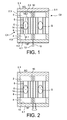
- a recovery and conversion device comprising a first cavity 2, a second cavity 4, a channel 6, said primary channel connecting the first cavity 2 and the second cavity 4, and second channels 8, said secondary channels, connecting the first cavity 2 and the second cavity 4.
- the primary channel extends along a longitudinal axis X.
- the assembly thus formed will be designated cells.
- the device represented on the figure 1 has two cells C1 and C2.
- the cavity 2 comprises a first and a second end wall 2.1, 2.2 and side walls 2.3.
- the first end wall 2.1 is intended to be in contact with a hot source SC; the wall 2.1 will be designated "hot wall” in the following description.
- the temperature reached by the hot wall 2.1 is such that it ensures the vaporization of the fluid contained in the device. It is therefore at least equal to the boiling temperature of the fluid. Examples of fluid will be given below.
- the hot source SC may for example be a face of an electronic component or any other source of heat.
- the cavity 2 will be designated in the following description "chamber” or "vaporization chamber”.
- the end wall 2.2 is traversed by the primary channel 6.
- the walls of the cavity 2 are made of a good thermal conductor material so as to ensure a homogeneous distribution of the temperature throughout the vaporization cavity 2.
- the second cavity 4 comprises a first and a second end wall 4.1, 4.2 and side walls 4.3.
- the end wall 4.1 comprises at least one wall 4.1 intended to be in contact with a cold source SF; wall 4.1 will be designated "cold wall” in the following description.
- the temperature of the cold wall 4.1 is such that it ensures the condensation of the vapor formed in the vaporization chamber 2. It is therefore lower than the boiling temperature of the fluid.
- the cold source SF is for example a finned radiator or directly the ambient air.
- the cavity 4 will be designated in the following description "chamber” or "condensation chamber”.
- the second end wall 4.2 is traversed by the primary channel 6.
- the walls of the second cavity are also made of a good thermal conductor material so as to ensure a homogeneous distribution of the temperature throughout the condensation cavity 4.
- the outer part 9 of the device disposed between the vaporization chamber 2 and the condensation chamber 4 and surrounding the primary channel 6 and the secondary channels 8, is formed of a thermal insulating material such as glass to prevent the heat conduction from the hot wall 2.1 to the cold wall 4.1.
- the device also comprises at least one element capable of transforming a mechanical stress into electrical energy.
- at least one element capable of transforming a mechanical stress into electrical energy.
- it is a piezoelectric material membrane 10 disposed in the cavity 2 against the hot wall 2.1.
- the membrane 10 is suspended by its lateral ends. Only part of it is then in contact with the hot wall 2.1 so as to promote its macroscopic deformation and thus increase the amount of electrical energy generated.
- the piezoelectric membrane 10 is connected to a system for collecting electrical energy, either directly a system 13 consuming the energy produced, or a storage system, such as a battery.
- the connections 12 and the system 13 are shown schematically.
- the connections can be made by brazing with a metal whose melting temperature is lower than that of melting of the piezoelectric material.
- the connection wires exit outside the device via channels made through the outer part of insulating material 9, side walls 4.3 and the cold wall 4.1.
- the connections are made before the assembly of the hot walls 2.1 and cold 4.1 with the outer part of insulating material 9.
- the primary channel 6 has an inner surface 14 such that it displaces G drops of liquid from the cavity 4 to the cavity 2.
- the inner surface 14 has sections 14.1, 14.2, 14.3 having different wettability properties, the sections being distributed along the X axis, so as to form a surface energy gradient surface.
- the sections are more and more wetting toward the first cavity 2.
- a surface has properties of low wettability vis-à-vis a liquid, when the contact angle ⁇ of a drop of said liquid is greater than 90 °.
- hydrophobic surface for a low wetting surface
- hydrophilic surface for a wetting surface
- the wetting properties can be obtained by depositing materials having different wetting affinities with the fluid.
- materials having different wetting affinities can for example, depositing SiOx which has low wettability with respect to water; the contact angle is between 20 ° and 40 ° or graphite fluorides (CFx) which have a hydrophobic character.
- CFx graphite fluorides
- the passage section of the primary channel 6 is greater than that of the secondary channels 8, and is such that it allows the circulation of drops of liquid while the secondary channels 8 are intended to allow only the passage of steam.
- the diameter of the primary channel is of the order of the capillary length, that is to say between 3 mm and 5 mm, advantageously of the order of 4 mm; preferably, the diameter of the secondary channel is of the order of the capillary length divided by 10, that is to say the diameter of the secondary channels is for example less than 0.4 mm.
- the device comprises several secondary channels 8. For example, they are distributed all around the primary channel. It can be envisaged that there is only one secondary channel which has an annular shape and completely surrounds the primary channel.
- the operation of the recovery and conversion device of the figure 1 is as follows: a drop of fluid evaporates suddenly in the vaporization chamber 2 by coming into contact with the hot wall 2.1 which is at a temperature above the boiling temperature of the fluid.
- the sudden evaporation generates a peak pressure in the chambers 2 and 4 and in the primary channels 6 and secondary 8 under the effect of the confinement of the gas.
- This pressure variation triggers a deformation of the piezoelectric membrane 10, which generates a voltage / an electric current at its terminals which is transported by the connections 12 to the consumer or storage system 13.
- the fluid in the gas state is almost instantaneously distributed in the volume of the chambers 2,4 and channels 6, 8 and condenses into a drop of fluid in the chamber 4 in contact with the cold wall 4.1.
- the condensed drop is then subjected to two forces: it is on the one hand attracted in the primary channel 6 of the chamber 4 to the chamber 2 by the internal surface gradient surface energy, this energy gradient created by the physicochemical characteristics of the internal wall 14 of the primary channel 6 allows the drop to minimize its energy by moving along the primary channel 6.
- the secondary channels 8 also have the function of not allowing underpressure to be generated in the chamber 4 due to the displacement of the drop. They therefore allow the pressure to accompany the drop during its transfer from the chamber 4 to the chamber 2. On arriving in the latter the drop is again vaporized suddenly and the cycle starts again.
- the size of the cell and the volume of fluid are for example such that a single drop circulates in the channel and then vaporizes and condenses.
- the operation of the device therefore leads to pressure peaks which are cyclic, from a hot source SC whose temperature does not vary or little or whose temperature varies slowly. These pressure peaks are converted into electricity by the piezoelectric membrane 10.
- the electrical signals are available on the connections of the membrane 10 and are cyclic in time. They can therefore be exploited by electronic circuits for energy recovery and be processed for storage and / or use.
- the device comprises two separate cells C1 and C2, a device with a single cell does not depart from the scope of the present invention.
- a large number of juxtaposed cells are provided so as to maximize the amount of electrical energy recovered.
- the cells may be evenly distributed or not by realizing, for example differences in density to adjust locally and controllably the thermal flux density passing through this structure.
- a piezoelectric membrane could be provided in the condensation chamber 4 only.
- piezoelectric membranes at the side walls and / or in the secondary channels.
- Each C101, C102 cells are similar to cells C1 and C2 of Figures 1 and 2 .
- the device however comprises a channel 116 connecting the chamber 102 of the cell C101 to the condensation chamber 104 'of the cell C102 and a channel 116' connecting the vaporization chamber 102 'of the cell C102 to the condensation chamber 104 of the cell C101.
- the channels 116 and 116 ' are intended to transfer the pressure generated in the vaporization chambers 102, 102' to the condensation chamber 104 ', 104 of the other cell.
- Secondary channels 108 connect the chamber 102 and the chamber 104.
- this coupling advantageously causes the cells to be driven together.
- the surface energy gradient surfaces may be replaced by electro-electrically biasing surfaces.
- an array of electrodes is provided in the wall of the primary channels and are activated gradually to move the drop.
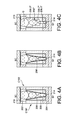
- the primary channel 206 has a variable passage section along the X axis. More particularly, it comprises a section of increasing passage along the axis X of the condensation chamber 204 towards the vaporization chamber 202.
- a piezoelectric membrane 210, 214 is disposed in each chamber 202, 204. In addition, it has a low wetting surface, or hydrophobic in the case of water.
- Secondary channels 208 are also provided.
- the wall of the primary channel 206 has a truncated cone shape.
- the radius of the primary channel 206 increases non-linearly along the X axis so that the inner surface of the primary channel has a convex profile.
- the primary channel 206 is composed of tubular portions 206.1", 206.2 “, 206.3" of increasing section, three in the example shown.
- a drop of liquid progressing in the primary channels is represented on each of the three Figures 4A to 4C .
- Sections 206.1, 206.2, 206.3 would no longer be of constant radius but would be cone-shaped or have a convex interior surface. Any other form facilitating the directional displacement of the drops of liquid is possible.
- the primary channel of Figures 4A to 4C may have a surface with a gradient of surface energy and / or electric polarization effect.
- the exemplary embodiment of the figure 3 in which two cells C101, C102 are coupled can be implemented with the devices of Figures 4A to 4C .
- the device may comprise cells of different types.
- the cells could have different means for moving the drop according to the cells and the arrangement.
- the dimensions of the primary channel and the vaporization and boiling chambers are chosen according to the size of the drops.
- the diameter of the primary channel is preferably equal to or less than that of the drop for surface effects to occur.
- the vaporization and boiling chambers preferably have a volume of between 1 and 10 times the volume of drop to maximize the confining effect and the amplitude of the pressure peaks.
- the channels can be straight or have more complex geometries.
- the channel section may be circular, elliptical, parallelepiped or any other.
- the device comprises a hot wall 2.1 at a temperature of between 110 ° C. and 150 ° C., a cold surface 4.1 at a temperature of between 50 ° C. and 80 ° C., a glass tube 9 connecting the hot wall 2.1 and the wall cold 4.1.
- the primary channel 6 is formed by a stainless steel tube.
- An annular secondary channel 8 is delimited between the stainless steel tube 7 and the glass tube 9, which has a thickness of 0.5 mm.
- the diameter of the primary channel 6 is for example between 1 mm and 4 mm.
- the condensation chamber 4 has a height of the order of 0.5 mm and a diameter of about 10 mm and a vaporization chamber 2 has a diameter of 15 mm and a height of between 1 mm and 3 mm. .
- the heat sources that can be used and that offer temperatures in the range of 110.degree. C. to 150.degree. C. are, for example, plant ducts that are equipped with autonomous sensors powered by the device according to the invention, or underground pipes difficult to reach equipped with autonomous sensors powered by the device according to the invention.
- the device comprises a single cell C1.
- the device comprises a plurality of cells C1, C2, C3 ... distributed in matrix.
- cells are distributed in an eight-pointed star pattern.
- FIG 5D it is the same distribution as that of the Figure 5C but with two types of cells C1, C2, C3 ... and C1 ', C2', C3 '... having different properties so as to adjust their performances or their functional domains and for example to be able to respond to domains different temperatures using fluids of different boiling temperatures, for example, water and ethanol.
- the cells may also have different dimensions.
- the various elements can be made by machining or any other suitable technique.
- microelectronic techniques such as insulating film deposits, conductive wires, lithographies, reactive ion etching (RIE for "reactive ion etching" in English terminology) can be used. Saxon) etc.
- RIE reactive ion etching
- the materials used may be other than those used in microelectronics, such as insulating ceramics, polymers, etc.
- the piezoelectric membranes may be in the form of macroscopic membranes or deposited in the form of thin layers.
- the surface energy gradient surface may for example be obtained by chemical vapor deposition (CVD) of materials with low wettability or good wettability.
- the resin is then removed.
- the first part deposited may be tower protected by a resin, so as to deposit on the second portion of the channel the complementary material with good wettability or low wettability.
- the piezoelectric material membrane (s) may or may be PZT, PLZT, PMNT, PMNZ or PFW.
- the fluid used may be water, solvents, fluids used in thermal applications, fluids charged with particles or mixtures of these fluids.
- solvents mention may be made of hydrofluoroethers.
- the device according to the invention makes it possible, through the use of phase change, to recover and convert thermal energy into electricity by means making it possible to generate periodic peaks of pressure and of voltage / electric current suitable for being used effectively. by electronic circuits for energy recovery.
- the device according to the invention makes it possible, by means of cell density adaptations, i.e. numbers of cells per unit area, to control the heat flow densities transferred by these architectures.
- the device according to the invention adapted to the recovery of thermal energy and its conversion into electrical energy can be used for the supply of low-power electronic devices, for example autonomous sensors.
- this device has the effect of removing heat, it then simultaneously plays the role of electricity cooling system.
- the device according to the invention can also be used as a thermal management device by adapting the quantity of liquid in each cell and the number of cells and their positioning as a function of the temperatures of the zones that it is desired to manage thermally.
- This management can be entirely passive or at least partially active in the case where electrowetting is implemented.
Landscapes
- Physical Or Chemical Processes And Apparatus (AREA)
Claims (16)
- Vorrichtung zur Rückgewinnung und Umwandlung von Wärmeenergie in elektrische Energie, die wenigstens eine Zelle (C1, C2, C101, C102) aufweist, umfassend:- einen ersten Hohlraum (2, 2'), wobei wenigstens ein Teil wenigstens einer Wandung (2.1) dazu vorgesehen ist, mit einer Wärmequelle (SC) in Kontakt zu stehen,- einen zweiten Hohlraum (4, 4'),wobei wenigstens ein Teil wenigstens einer Wandung (4.1) dazu vorgesehen ist, mit einer Kältequelle (SF) in Kontakt zu stehen,- ein Primärkanal (6), der den ersten Hohlraum (2) und den zweiten Hohlraum (4) verbindet und dazu vorgesehen ist, ein Fluid in Form von flüssigen Fluidtropfen zu transportieren, wobei der Primärkanal Mittel umfasst, die den Transport der flüssigen Fluidtropfen von dem zweiten Hohlraum (4) zu dem ersten Hohlraum (2) gewährleisten,- wenigstens einen Sekundärkanal (8), der den ersten Hohlraum (2) und den zweiten Hohlraum (4) verbindet und dazu vorgesehen ist, das Fluid in Gasform zu transportieren,- wenigstens ein piezoelektrisches Material (10), das in wenigstens einem aus ersten (2) und zweitem (4) Hohlraum angeordnet ist,- ein flüssiges und gasförmiges Fluid, das in der Zelle begrenzt ist,- Verbindungsmittel (12) von dem piezoelektrischen Material (10) zu einer Vorrichtung zur Rückgewinnung der von dem piezoelektrischen Material (10) erzeugten elektrischen Energie.
- Vorrichtung zur Rückgewinnung und Umwandlung von Wärmeenergie in elektrische Energie nach Anspruch 1, wobei die Mittel, die den Transport der flüssigen Fluidtropfen gewährleisten, durch die Innenfläche des Primärkanals gebildet sind, mit einem Oberflächenenergie-Gradienten, der derart ausgerichtet ist, dass sich die Flüssigkeitstropfen von dem zweiten Hohlraum (4, 4') zu dem ersten Hohlraum (2, 2') verlagern.
- Vorrichtung zur Rückgewinnung und Umwandlung von Wärmeenergie in elektrische Energie nach Anspruch 2, wobei der Oberflächenenergie-Gradient durch wenigstens einen ersten und einen zweiten Oberflächenabschnitt erhalten wird, die aufeinanderfolgend in dieser Reihenfolge zwischen dem zweiten Hohlraum und dem ersten Hohlraum angeordnet sind, wobei jeder der Abschnitte Benetzbarkeitseigenschaften gegenüber dem Fluid aufweist, wobei die Benetzbarkeit des zweiten Abschnitts größer ist als jene des ersten Abschnitts, wobei die Benetzbarkeitseigenschaften vorteilhafterweise durch eine Schicht eines Materials erzielt werden, das die genannten Benetzbarkeitseigenschaften aufweist und/oder durch Strukturierung wenigstens eines Abschnitts der Innenfläche.
- Vorrichtung zur Rückgewinnung und Umwandlung von Wärmeenergie in elektrische Energie nach Anspruch 1, wobei die Mittel, die den Transport der flüssigen Fluidtropfen gewährleisten, vom elektrostatischen Typ sind, und beispielsweise das Phänomen der Elektrobenetzung umsetzen.
- Vorrichtung zur Rückgewinnung und Umwandlung von Wärmeenergie in elektrische Energie nach einem der Ansprüche 1 bis 4, wobei der Primärkanal (6) einen zunehmenden Durchlassquerschnitt des zweiten Hohlraums (4, 4') zu dem ersten Hohlraum (2, 2') aufweist, wobei vorteilhafterweise wenigstens ein Teil der Innenfläche des Primärkanals (6) auf der Seite des zweiten Hohlraums (4, 4') Eigenschaften einer schwachen Benetzbarkeit gegenüber dem Fluid aufweist.
- Vorrichtung zur Rückgewinnung und Umwandlung von Wärmeenergie in elektrische Energie gemäß Anspruch 5, wobei der Primärkanal (6) eine auskragende Form aufweist, oder wobei der Primärkanal (6) wenigstens zwei aufeinanderfolgende Abschnitte umfasst, die unterschiedliche Durchlassquerschnitte aufweisen, wobei die Durchlassquerschnitte von dem zweiten Hohlraum (4) zu dem ersten Hohlraum (2) zunehmen.
- Vorrichtung zur Rückgewinnung und Umwandlung von Wärmeenergie in elektrische Energie nach einem der Ansprüche 1 bis 6, wobei der Durchlassquerschnitt des Sekundärkanals (8) derart ist, dass er den Durchlass von Flüssigkeitstropfen verhindert.
- Vorrichtung zur Rückgewinnung und Umwandlung von Wärmeenergie in elektrische Energie nach einem der Ansprüche 1 bis 7, wobei der Sekundärkanal (8) in den zweiten Hohlraum (4) in der Nähe eines Endes des Primärkanals (6) mündet, der wiederum in den zweiten Hohlraum (2) mündet.
- Vorrichtung zur Rückgewinnung und Umwandlung von Wärmeenergie in elektrische Energie nach einem der Ansprüche 1 bis 8, welche wenigstens eine erste (C101) und eine zweite (C102) Zelle aufweist, und einen Transferkanal (116), der den ersten Hohlraum (102) der ersten Zelle (C101) mit dem zweiten Hohlraum (104') der zweiten Zelle (C102) sowie den zweiten Hohlraum (104) der ersten Zelle (C101) mit dem ersten Hohlraum (102') der zweiten Zelle (C102) verbindet.
- Vorrichtung zur Rückgewinnung und Umwandlung von Wärmeenergie in elektrische Energie nach einem der Ansprüche 1 bis 9, wobei die Wandungen (2.1, 40.1) des ersten (2) und des zweiten (4) Hohlraums aus einem Material mit guten Wärmeleiteigenschaften gebildet sind und wobei die Vorrichtung ein äußeres Element (9) umfasst, das die Wandungen des ersten (2) und des zweiten (4) Hohlraums verbindet, wobei das äußere Element (9) aus einem wärmeisolierenden Material gebildet ist.
- Vorrichtung zur Rückgewinnung und Umwandlung von Wärmeenergie in elektrische Energie nach einem der Ansprüche 1 bis 10, wobei das piezoelektrische Material oder die piezoelektrischen Materialien (10, 14), die in einem aus erstem (2) und zweitem (4) Hohlraum oder in dem ersten (2) und dem zweiten Hohlraum(4) vorliegen können, in Kontakt mit der Wandung (2.1, 4.1) ist/sind, welche dazu vorgesehen ist, in Kontakt mit der Wärmequelle (SC) und/oder der Kältequelle (SF) zu stehen.
- Vorrichtung zur Rückgewinnung und Umwandlung von Wärmeenergie in elektrische Energie nach einem der Ansprüche 1 bis 11, wobei das piezoelektrische Material oder die piezoelektrischen Materialien (10, 14) in der Form schwebender Membranen vorliegt/vorliegen.
- Vorrichtung zur Rückgewinnung und Umwandlung von Wärmeenergie in elektrische Energie nach einem der Ansprüche 1 bis 12, wobei der Durchmesser des Primärkanals (6) denjenigen der Flüssigkeitstropfen entspricht oder kleiner ist.
- Vorrichtung zur Rückgewinnung und Umwandlung von Wärmeenergie in elektrische Energie nach einem der Ansprüche 1 bis 13, wobei das Volumen des ersten (2) und/oder des zweiten (4) Hohlraums zwischen dem Ein- und Zehnfachen des Volumens eines Flüssigkeitstropfens liegt.
- Vorrichtung zur Rückgewinnung und Umwandlung von Wärmeenergie in elektrische Energie nach einem der Ansprüche 1 bis 14, welche eine Mehrzahl von benachbarten Zellen (C1, C2) aufweist, wobei die Zellen (C1, C2) mit einer variablen Dichte abhängig von der örtlichen Dichte des von der Wärmequelle ausgegebenen Wärmeflusses verteilt sind.
- Vorrichtung zur Rückgewinnung und Umwandlung von Wärmeenergie in elektrische Energie nach einem der Ansprüche 1 bis 15, wobei die Temperatur der Wärmequelle (SC) derart ist, dass die Temperatur der Wandung (2.1) des ersten Hohlraums (2) in Kontakt mit dieser Wärmquelle wenigstens gleich der Siedetemperatur des Fluids ist, wobei die Wärmequelle (SC) vorteilhafterweise durch eine tragbare elektronische Vorrichtung gebildet ist.
Applications Claiming Priority (2)
| Application Number | Priority Date | Filing Date | Title |
|---|---|---|---|
| FR1251368A FR2986908B1 (fr) | 2012-02-14 | 2012-02-14 | Dispositif de recuperation et de conversion d'energie thermique en energie electrique |
| PCT/EP2013/052815 WO2013120869A1 (fr) | 2012-02-14 | 2013-02-13 | Dispositif de recuperation et de conversion d'energie thermique en energie electrique |
Publications (2)
| Publication Number | Publication Date |
|---|---|
| EP2815498A1 EP2815498A1 (de) | 2014-12-24 |
| EP2815498B1 true EP2815498B1 (de) | 2016-01-20 |
Family
ID=47748593
Family Applications (1)
| Application Number | Title | Priority Date | Filing Date |
|---|---|---|---|
| EP13705750.1A Not-in-force EP2815498B1 (de) | 2012-02-14 | 2013-02-13 | Vorrichtung zur rückgewinnung und umwandlung von wärmeenergie in elektrische energie |
Country Status (5)
| Country | Link |
|---|---|
| US (1) | US9444371B2 (de) |
| EP (1) | EP2815498B1 (de) |
| CN (1) | CN104145414A (de) |
| FR (1) | FR2986908B1 (de) |
| WO (1) | WO2013120869A1 (de) |
Families Citing this family (12)
| Publication number | Priority date | Publication date | Assignee | Title |
|---|---|---|---|---|
| FR2973944B1 (fr) | 2011-04-06 | 2014-01-10 | Commissariat Energie Atomique | Emetteur pour systeme thermophotovoltaique et systeme thermophotovoltaique comportant au moins un tel emetteur |
| FR2977983B1 (fr) | 2011-07-11 | 2013-08-16 | Commissariat Energie Atomique | Systeme de conversion d'energie thermique en energie electrique |
| FR3008690B1 (fr) | 2013-07-22 | 2016-12-23 | Commissariat Energie Atomique | Dispositif comportant un canal fluidique muni d'au moins un systeme micro ou nanoelectronique et procede de realisation d'un tel dispositif |
| FR3008691B1 (fr) | 2013-07-22 | 2016-12-23 | Commissariat Energie Atomique | Dispositif comportant un canal fluidique muni d'au moins un systeme micro ou nanoelectronique et procede de realisation d'un tel dispositif |
| FR3009907B1 (fr) * | 2013-08-20 | 2015-09-18 | Commissariat Energie Atomique | Dispositif de conversion d'energie thermique en energie electrique |
| US9793829B2 (en) * | 2013-09-25 | 2017-10-17 | Prime Photonics, Lc | Magneto-thermoelectric generator for energy harvesting |
| FR3032845B1 (fr) | 2015-02-13 | 2017-03-10 | St Microelectronics Crolles 2 Sas | Dispositif de recuperation d'energie thermique |
| US10303647B2 (en) * | 2015-07-15 | 2019-05-28 | Mellanox Technologies, Ltd. | Access control in peer-to-peer transactions over a peripheral component bus |
| CN105897049B (zh) * | 2016-06-06 | 2017-12-19 | 南京航空航天大学 | 一种转动碰撞式月面压电能量收集装置及其工作方法 |
| EP3331149A1 (de) * | 2016-12-02 | 2018-06-06 | Blunergy SA | Thermoelektrischer generator |
| EP3431263B1 (de) * | 2017-07-21 | 2021-04-21 | CL Schutzrechtsverwaltungs GmbH | Verfahren zum betrieb von mindestens einer vorrichtung zur generativen fertigung dreidimensionaler objekte |
| GB2597900B (en) * | 2020-06-11 | 2022-08-24 | Katrick Tech Limited | Heat engine and method of manufacture |
Family Cites Families (14)
| Publication number | Priority date | Publication date | Assignee | Title |
|---|---|---|---|---|
| US6360775B1 (en) | 1998-12-23 | 2002-03-26 | Agilent Technologies, Inc. | Capillary fluid switch with asymmetric bubble chamber |
| US7411337B2 (en) * | 2001-11-16 | 2008-08-12 | Intel Corporation | Electrical energy-generating system and devices and methods related thereto |
| GB0311236D0 (en) * | 2003-05-16 | 2003-06-18 | Acton Elizabeth | Improved method of freezing large volumes |
| US20060173344A1 (en) * | 2005-01-19 | 2006-08-03 | Siemens Medical Solutions Usa, Inc. | Method for using a refrigeration system to remove waste heat from an ultrasound transducer |
| CA2595473A1 (en) * | 2005-02-03 | 2006-08-10 | University Of Manitoba | Micro heat engine and method of manufacturing |
| GB2447600A (en) | 2006-01-25 | 2008-09-17 | Univ California | Energy harvesting by means of thermo-mechanical device utilizing bistable ferromagnets |
| JP4987847B2 (ja) | 2006-02-27 | 2012-07-25 | 京セラ株式会社 | セラミック部材の製造方法 |
| WO2009038080A1 (ja) | 2007-09-18 | 2009-03-26 | Kyocera Corporation | 積層型圧電素子、これを備えた噴射装置及び燃料噴射システム |
| FR2951874B1 (fr) * | 2009-10-26 | 2011-12-09 | St Microelectronics Crolles 2 | Generateur thermoelectrique |
| JP5660288B2 (ja) | 2010-01-05 | 2015-01-28 | セイコーエプソン株式会社 | 液体噴射ヘッド、液体噴射装置及び圧電素子並びに液体噴射ヘッドの製造方法 |
| FR2973944B1 (fr) | 2011-04-06 | 2014-01-10 | Commissariat Energie Atomique | Emetteur pour systeme thermophotovoltaique et systeme thermophotovoltaique comportant au moins un tel emetteur |
| FR2977121B1 (fr) | 2011-06-22 | 2014-04-25 | Commissariat Energie Atomique | Systeme de gestion thermique a materiau a volume variable |
| US20140174085A1 (en) * | 2012-12-21 | 2014-06-26 | Elwha LLC. | Heat engine |
| FR3008691B1 (fr) | 2013-07-22 | 2016-12-23 | Commissariat Energie Atomique | Dispositif comportant un canal fluidique muni d'au moins un systeme micro ou nanoelectronique et procede de realisation d'un tel dispositif |
-
2012
- 2012-02-14 FR FR1251368A patent/FR2986908B1/fr not_active Expired - Fee Related
-
2013
- 2013-02-13 CN CN201380009315.6A patent/CN104145414A/zh active Pending
- 2013-02-13 US US14/378,267 patent/US9444371B2/en not_active Expired - Fee Related
- 2013-02-13 WO PCT/EP2013/052815 patent/WO2013120869A1/fr not_active Ceased
- 2013-02-13 EP EP13705750.1A patent/EP2815498B1/de not_active Not-in-force
Also Published As
| Publication number | Publication date |
|---|---|
| CN104145414A (zh) | 2014-11-12 |
| US9444371B2 (en) | 2016-09-13 |
| WO2013120869A1 (fr) | 2013-08-22 |
| FR2986908A1 (fr) | 2013-08-16 |
| US20150001990A1 (en) | 2015-01-01 |
| EP2815498A1 (de) | 2014-12-24 |
| FR2986908B1 (fr) | 2014-03-28 |
Similar Documents
| Publication | Publication Date | Title |
|---|---|---|
| EP2815498B1 (de) | Vorrichtung zur rückgewinnung und umwandlung von wärmeenergie in elektrische energie | |
| EP3732744B1 (de) | Gerät für die temperaturkontrolle einer batterie bzw. eines elektronischen kraftgerät. | |
| EP1881538B1 (de) | Elektronisches Bauelement für Wärmetransport durch Verdampfen und Kondensation, sowie Verfahren zur Herstellung. | |
| EP2904343B1 (de) | Wärmetauscher für thermisches speichersystem | |
| EP2291871B1 (de) | Vorrichtung zur erzeugung von strom, wärmetauscherbündel mit derartiger vorrichtung und wärmetauscher mit derartigem bündel | |
| EP2181301A1 (de) | Passive wärmereglervorrichtung mit flüssigkeitsmikrokreislauf und kapillarpumpung | |
| FR2977121A1 (fr) | Systeme de gestion thermique a materiau a volume variable | |
| EP2564176A1 (de) | Vorrichtung zur bildung eines manometers zum messen eines zweiphasigen flüssigkeitsdrucks, zugehöriges verfahren zur herstellung und flüssigkeitsnetzwerk | |
| EP2803085A1 (de) | Passive wärmeverwaltungsvorrichtung | |
| EP3355019A1 (de) | Vorrichtung zur Kühlung | |
| EP2430694B1 (de) | Kompakte brennstoffzelle | |
| FR2951874A1 (fr) | Generateur thermoelectrique | |
| EP2478321A1 (de) | Wärmetauschervorrichtung mit begrenztem konvektionssieden und verbesserter effizienz | |
| FR2990061A1 (fr) | Source d'energie et procede d'alimentation d'un systeme autarcique de consommateurs electriques et son procede d'utilisation | |
| WO2012160162A1 (fr) | Pile a combustible a gestion thermique amelioree | |
| WO2015025106A2 (fr) | Dispositif de conversion d'energie thermique en energie electrique | |
| EP2591513B1 (de) | Vorrichtung zur erzeugung von strom und/oder spannung auf basis eines in einer fliessenden flüssigkeit platzierten thermoelektrischen moduls | |
| FR2813662A1 (fr) | Evaporateur capillaire pour boucle de transfert | |
| FR3138687A1 (fr) | Echangeur de chaleur | |
| EP4323711B1 (de) | Zweiphasige wärmeübertragungsvorrichtung mit flüssigkeitsüberlauftank | |
| EP3194874B1 (de) | Wärmerohr und verfahren zur herstellung eines wärmerohrs | |
| FR3081214A1 (fr) | Evaporateur d'une boucle fluide et boucle fluide comprenant un tel evaporateur | |
| FR3077627A1 (fr) | Dispositif detendeur destine a etre installe dans un circuit de climatisation | |
| WO2019007941A1 (fr) | Dispositif de régulation thermique d'au moins un élément de stockage d'énergie électrique | |
| FR3041156A1 (fr) | Module et dispositif thermo electriques, notamment destines a generer un courant electrique dans un vehicule automobile |
Legal Events
| Date | Code | Title | Description |
|---|---|---|---|
| PUAI | Public reference made under article 153(3) epc to a published international application that has entered the european phase |
Free format text: ORIGINAL CODE: 0009012 |
|
| 17P | Request for examination filed |
Effective date: 20140910 |
|
| AK | Designated contracting states |
Kind code of ref document: A1 Designated state(s): AL AT BE BG CH CY CZ DE DK EE ES FI FR GB GR HR HU IE IS IT LI LT LU LV MC MK MT NL NO PL PT RO RS SE SI SK SM TR |
|
| AX | Request for extension of the european patent |
Extension state: BA ME |
|
| RIN1 | Information on inventor provided before grant (corrected) |
Inventor name: MONFRAY, STEPHANE Inventor name: SKOTNICKI, THOMAS Inventor name: SOUPREMANIEN, ULRICH Inventor name: OLLIER, EMMANUEL |
|
| DAX | Request for extension of the european patent (deleted) | ||
| GRAP | Despatch of communication of intention to grant a patent |
Free format text: ORIGINAL CODE: EPIDOSNIGR1 |
|
| INTG | Intention to grant announced |
Effective date: 20150717 |
|
| RIN1 | Information on inventor provided before grant (corrected) |
Inventor name: SOUPREMANIEN, ULRICH Inventor name: SKOTNICKI, THOMAS Inventor name: MONFRAY, STEPHANE Inventor name: OLLIER, EMMANUEL |
|
| GRAS | Grant fee paid |
Free format text: ORIGINAL CODE: EPIDOSNIGR3 |
|
| GRAA | (expected) grant |
Free format text: ORIGINAL CODE: 0009210 |
|
| AK | Designated contracting states |
Kind code of ref document: B1 Designated state(s): AL AT BE BG CH CY CZ DE DK EE ES FI FR GB GR HR HU IE IS IT LI LT LU LV MC MK MT NL NO PL PT RO RS SE SI SK SM TR |
|
| REG | Reference to a national code |
Ref country code: GB Ref legal event code: FG4D Free format text: NOT ENGLISH |
|
| REG | Reference to a national code |
Ref country code: CH Ref legal event code: EP |
|
| REG | Reference to a national code |
Ref country code: IE Ref legal event code: FG4D Free format text: LANGUAGE OF EP DOCUMENT: FRENCH |
|
| REG | Reference to a national code |
Ref country code: AT Ref legal event code: REF Ref document number: 772127 Country of ref document: AT Kind code of ref document: T Effective date: 20160215 |
|
| REG | Reference to a national code |
Ref country code: FR Ref legal event code: PLFP Year of fee payment: 4 |
|
| REG | Reference to a national code |
Ref country code: DE Ref legal event code: R096 Ref document number: 602013004742 Country of ref document: DE |
|
| REG | Reference to a national code |
Ref country code: LT Ref legal event code: MG4D Ref country code: NL Ref legal event code: MP Effective date: 20160120 |
|
| PG25 | Lapsed in a contracting state [announced via postgrant information from national office to epo] |
Ref country code: BE Free format text: LAPSE BECAUSE OF NON-PAYMENT OF DUE FEES Effective date: 20160229 |
|
| REG | Reference to a national code |
Ref country code: AT Ref legal event code: MK05 Ref document number: 772127 Country of ref document: AT Kind code of ref document: T Effective date: 20160120 |
|
| PG25 | Lapsed in a contracting state [announced via postgrant information from national office to epo] |
Ref country code: NL Free format text: LAPSE BECAUSE OF FAILURE TO SUBMIT A TRANSLATION OF THE DESCRIPTION OR TO PAY THE FEE WITHIN THE PRESCRIBED TIME-LIMIT Effective date: 20160120 |
|
| PG25 | Lapsed in a contracting state [announced via postgrant information from national office to epo] |
Ref country code: FI Free format text: LAPSE BECAUSE OF FAILURE TO SUBMIT A TRANSLATION OF THE DESCRIPTION OR TO PAY THE FEE WITHIN THE PRESCRIBED TIME-LIMIT Effective date: 20160120 Ref country code: GR Free format text: LAPSE BECAUSE OF FAILURE TO SUBMIT A TRANSLATION OF THE DESCRIPTION OR TO PAY THE FEE WITHIN THE PRESCRIBED TIME-LIMIT Effective date: 20160421 Ref country code: HR Free format text: LAPSE BECAUSE OF FAILURE TO SUBMIT A TRANSLATION OF THE DESCRIPTION OR TO PAY THE FEE WITHIN THE PRESCRIBED TIME-LIMIT Effective date: 20160120 Ref country code: NO Free format text: LAPSE BECAUSE OF FAILURE TO SUBMIT A TRANSLATION OF THE DESCRIPTION OR TO PAY THE FEE WITHIN THE PRESCRIBED TIME-LIMIT Effective date: 20160420 Ref country code: IT Free format text: LAPSE BECAUSE OF FAILURE TO SUBMIT A TRANSLATION OF THE DESCRIPTION OR TO PAY THE FEE WITHIN THE PRESCRIBED TIME-LIMIT Effective date: 20160120 Ref country code: ES Free format text: LAPSE BECAUSE OF FAILURE TO SUBMIT A TRANSLATION OF THE DESCRIPTION OR TO PAY THE FEE WITHIN THE PRESCRIBED TIME-LIMIT Effective date: 20160120 |
|
| PG25 | Lapsed in a contracting state [announced via postgrant information from national office to epo] |
Ref country code: LV Free format text: LAPSE BECAUSE OF FAILURE TO SUBMIT A TRANSLATION OF THE DESCRIPTION OR TO PAY THE FEE WITHIN THE PRESCRIBED TIME-LIMIT Effective date: 20160120 Ref country code: PL Free format text: LAPSE BECAUSE OF FAILURE TO SUBMIT A TRANSLATION OF THE DESCRIPTION OR TO PAY THE FEE WITHIN THE PRESCRIBED TIME-LIMIT Effective date: 20160120 Ref country code: PT Free format text: LAPSE BECAUSE OF FAILURE TO SUBMIT A TRANSLATION OF THE DESCRIPTION OR TO PAY THE FEE WITHIN THE PRESCRIBED TIME-LIMIT Effective date: 20160520 Ref country code: IS Free format text: LAPSE BECAUSE OF FAILURE TO SUBMIT A TRANSLATION OF THE DESCRIPTION OR TO PAY THE FEE WITHIN THE PRESCRIBED TIME-LIMIT Effective date: 20160520 Ref country code: LT Free format text: LAPSE BECAUSE OF FAILURE TO SUBMIT A TRANSLATION OF THE DESCRIPTION OR TO PAY THE FEE WITHIN THE PRESCRIBED TIME-LIMIT Effective date: 20160120 Ref country code: RS Free format text: LAPSE BECAUSE OF FAILURE TO SUBMIT A TRANSLATION OF THE DESCRIPTION OR TO PAY THE FEE WITHIN THE PRESCRIBED TIME-LIMIT Effective date: 20160120 Ref country code: SE Free format text: LAPSE BECAUSE OF FAILURE TO SUBMIT A TRANSLATION OF THE DESCRIPTION OR TO PAY THE FEE WITHIN THE PRESCRIBED TIME-LIMIT Effective date: 20160120 Ref country code: AT Free format text: LAPSE BECAUSE OF FAILURE TO SUBMIT A TRANSLATION OF THE DESCRIPTION OR TO PAY THE FEE WITHIN THE PRESCRIBED TIME-LIMIT Effective date: 20160120 |
|
| REG | Reference to a national code |
Ref country code: CH Ref legal event code: PL |
|
| REG | Reference to a national code |
Ref country code: DE Ref legal event code: R097 Ref document number: 602013004742 Country of ref document: DE |
|
| PG25 | Lapsed in a contracting state [announced via postgrant information from national office to epo] |
Ref country code: DK Free format text: LAPSE BECAUSE OF FAILURE TO SUBMIT A TRANSLATION OF THE DESCRIPTION OR TO PAY THE FEE WITHIN THE PRESCRIBED TIME-LIMIT Effective date: 20160120 Ref country code: LI Free format text: LAPSE BECAUSE OF NON-PAYMENT OF DUE FEES Effective date: 20160229 Ref country code: CH Free format text: LAPSE BECAUSE OF NON-PAYMENT OF DUE FEES Effective date: 20160229 Ref country code: EE Free format text: LAPSE BECAUSE OF FAILURE TO SUBMIT A TRANSLATION OF THE DESCRIPTION OR TO PAY THE FEE WITHIN THE PRESCRIBED TIME-LIMIT Effective date: 20160120 Ref country code: MC Free format text: LAPSE BECAUSE OF FAILURE TO SUBMIT A TRANSLATION OF THE DESCRIPTION OR TO PAY THE FEE WITHIN THE PRESCRIBED TIME-LIMIT Effective date: 20160120 |
|
| PLBE | No opposition filed within time limit |
Free format text: ORIGINAL CODE: 0009261 |
|
| STAA | Information on the status of an ep patent application or granted ep patent |
Free format text: STATUS: NO OPPOSITION FILED WITHIN TIME LIMIT |
|
| PG25 | Lapsed in a contracting state [announced via postgrant information from national office to epo] |
Ref country code: CZ Free format text: LAPSE BECAUSE OF FAILURE TO SUBMIT A TRANSLATION OF THE DESCRIPTION OR TO PAY THE FEE WITHIN THE PRESCRIBED TIME-LIMIT Effective date: 20160120 Ref country code: SM Free format text: LAPSE BECAUSE OF FAILURE TO SUBMIT A TRANSLATION OF THE DESCRIPTION OR TO PAY THE FEE WITHIN THE PRESCRIBED TIME-LIMIT Effective date: 20160120 Ref country code: SK Free format text: LAPSE BECAUSE OF FAILURE TO SUBMIT A TRANSLATION OF THE DESCRIPTION OR TO PAY THE FEE WITHIN THE PRESCRIBED TIME-LIMIT Effective date: 20160120 Ref country code: RO Free format text: LAPSE BECAUSE OF FAILURE TO SUBMIT A TRANSLATION OF THE DESCRIPTION OR TO PAY THE FEE WITHIN THE PRESCRIBED TIME-LIMIT Effective date: 20160120 |
|
| REG | Reference to a national code |
Ref country code: IE Ref legal event code: MM4A |
|
| 26N | No opposition filed |
Effective date: 20161021 |
|
| PG25 | Lapsed in a contracting state [announced via postgrant information from national office to epo] |
Ref country code: IE Free format text: LAPSE BECAUSE OF NON-PAYMENT OF DUE FEES Effective date: 20160213 |
|
| PG25 | Lapsed in a contracting state [announced via postgrant information from national office to epo] |
Ref country code: BG Free format text: LAPSE BECAUSE OF FAILURE TO SUBMIT A TRANSLATION OF THE DESCRIPTION OR TO PAY THE FEE WITHIN THE PRESCRIBED TIME-LIMIT Effective date: 20160420 Ref country code: SI Free format text: LAPSE BECAUSE OF FAILURE TO SUBMIT A TRANSLATION OF THE DESCRIPTION OR TO PAY THE FEE WITHIN THE PRESCRIBED TIME-LIMIT Effective date: 20160120 |
|
| REG | Reference to a national code |
Ref country code: FR Ref legal event code: PLFP Year of fee payment: 5 |
|
| PGFP | Annual fee paid to national office [announced via postgrant information from national office to epo] |
Ref country code: FR Payment date: 20170228 Year of fee payment: 5 Ref country code: DE Payment date: 20170210 Year of fee payment: 5 |
|
| PGFP | Annual fee paid to national office [announced via postgrant information from national office to epo] |
Ref country code: GB Payment date: 20170214 Year of fee payment: 5 |
|
| PG25 | Lapsed in a contracting state [announced via postgrant information from national office to epo] |
Ref country code: MT Free format text: LAPSE BECAUSE OF FAILURE TO SUBMIT A TRANSLATION OF THE DESCRIPTION OR TO PAY THE FEE WITHIN THE PRESCRIBED TIME-LIMIT Effective date: 20160120 |
|
| PG25 | Lapsed in a contracting state [announced via postgrant information from national office to epo] |
Ref country code: HU Free format text: LAPSE BECAUSE OF FAILURE TO SUBMIT A TRANSLATION OF THE DESCRIPTION OR TO PAY THE FEE WITHIN THE PRESCRIBED TIME-LIMIT; INVALID AB INITIO Effective date: 20130213 |
|
| PG25 | Lapsed in a contracting state [announced via postgrant information from national office to epo] |
Ref country code: CY Free format text: LAPSE BECAUSE OF FAILURE TO SUBMIT A TRANSLATION OF THE DESCRIPTION OR TO PAY THE FEE WITHIN THE PRESCRIBED TIME-LIMIT Effective date: 20160120 Ref country code: LU Free format text: LAPSE BECAUSE OF NON-PAYMENT OF DUE FEES Effective date: 20160213 Ref country code: MK Free format text: LAPSE BECAUSE OF FAILURE TO SUBMIT A TRANSLATION OF THE DESCRIPTION OR TO PAY THE FEE WITHIN THE PRESCRIBED TIME-LIMIT Effective date: 20160120 |
|
| REG | Reference to a national code |
Ref country code: DE Ref legal event code: R119 Ref document number: 602013004742 Country of ref document: DE |
|
| GBPC | Gb: european patent ceased through non-payment of renewal fee |
Effective date: 20180213 |
|
| PG25 | Lapsed in a contracting state [announced via postgrant information from national office to epo] |
Ref country code: AL Free format text: LAPSE BECAUSE OF FAILURE TO SUBMIT A TRANSLATION OF THE DESCRIPTION OR TO PAY THE FEE WITHIN THE PRESCRIBED TIME-LIMIT Effective date: 20160120 Ref country code: TR Free format text: LAPSE BECAUSE OF FAILURE TO SUBMIT A TRANSLATION OF THE DESCRIPTION OR TO PAY THE FEE WITHIN THE PRESCRIBED TIME-LIMIT Effective date: 20160120 |
|
| REG | Reference to a national code |
Ref country code: FR Ref legal event code: ST Effective date: 20181031 |
|
| PG25 | Lapsed in a contracting state [announced via postgrant information from national office to epo] |
Ref country code: DE Free format text: LAPSE BECAUSE OF NON-PAYMENT OF DUE FEES Effective date: 20180901 |
|
| PG25 | Lapsed in a contracting state [announced via postgrant information from national office to epo] |
Ref country code: GB Free format text: LAPSE BECAUSE OF NON-PAYMENT OF DUE FEES Effective date: 20180213 Ref country code: FR Free format text: LAPSE BECAUSE OF NON-PAYMENT OF DUE FEES Effective date: 20180228 |