EP2815903A2 - Mode de stationnement activé par GPS pour systèmes de suspension réglable - Google Patents
Mode de stationnement activé par GPS pour systèmes de suspension réglable Download PDFInfo
- Publication number
- EP2815903A2 EP2815903A2 EP14173488.9A EP14173488A EP2815903A2 EP 2815903 A2 EP2815903 A2 EP 2815903A2 EP 14173488 A EP14173488 A EP 14173488A EP 2815903 A2 EP2815903 A2 EP 2815903A2
- Authority
- EP
- European Patent Office
- Prior art keywords
- vehicle
- approaching
- suspension system
- air suspension
- park
- Prior art date
- Legal status (The legal status is an assumption and is not a legal conclusion. Google has not performed a legal analysis and makes no representation as to the accuracy of the status listed.)
- Ceased
Links
Images

Classifications
-
- B—PERFORMING OPERATIONS; TRANSPORTING
- B60—VEHICLES IN GENERAL
- B60G—VEHICLE SUSPENSION ARRANGEMENTS
- B60G17/00—Resilient suspensions having means for adjusting the spring or vibration-damper characteristics, for regulating the distance between a supporting surface and a sprung part of vehicle or for locking suspension during use to meet varying vehicular or surface conditions, e.g. due to speed or load
- B60G17/015—Resilient suspensions having means for adjusting the spring or vibration-damper characteristics, for regulating the distance between a supporting surface and a sprung part of vehicle or for locking suspension during use to meet varying vehicular or surface conditions, e.g. due to speed or load the regulating means comprising electric or electronic elements
- B60G17/016—Resilient suspensions having means for adjusting the spring or vibration-damper characteristics, for regulating the distance between a supporting surface and a sprung part of vehicle or for locking suspension during use to meet varying vehicular or surface conditions, e.g. due to speed or load the regulating means comprising electric or electronic elements characterised by their responsiveness, when the vehicle is travelling, to specific motion, a specific condition, or driver input
-
- B—PERFORMING OPERATIONS; TRANSPORTING
- B60—VEHICLES IN GENERAL
- B60G—VEHICLE SUSPENSION ARRANGEMENTS
- B60G17/00—Resilient suspensions having means for adjusting the spring or vibration-damper characteristics, for regulating the distance between a supporting surface and a sprung part of vehicle or for locking suspension during use to meet varying vehicular or surface conditions, e.g. due to speed or load
- B60G17/015—Resilient suspensions having means for adjusting the spring or vibration-damper characteristics, for regulating the distance between a supporting surface and a sprung part of vehicle or for locking suspension during use to meet varying vehicular or surface conditions, e.g. due to speed or load the regulating means comprising electric or electronic elements
- B60G17/0152—Resilient suspensions having means for adjusting the spring or vibration-damper characteristics, for regulating the distance between a supporting surface and a sprung part of vehicle or for locking suspension during use to meet varying vehicular or surface conditions, e.g. due to speed or load the regulating means comprising electric or electronic elements characterised by the action on a particular type of suspension unit
- B60G17/0155—Resilient suspensions having means for adjusting the spring or vibration-damper characteristics, for regulating the distance between a supporting surface and a sprung part of vehicle or for locking suspension during use to meet varying vehicular or surface conditions, e.g. due to speed or load the regulating means comprising electric or electronic elements characterised by the action on a particular type of suspension unit pneumatic unit
-
- B—PERFORMING OPERATIONS; TRANSPORTING
- B60—VEHICLES IN GENERAL
- B60G—VEHICLE SUSPENSION ARRANGEMENTS
- B60G17/00—Resilient suspensions having means for adjusting the spring or vibration-damper characteristics, for regulating the distance between a supporting surface and a sprung part of vehicle or for locking suspension during use to meet varying vehicular or surface conditions, e.g. due to speed or load
- B60G17/015—Resilient suspensions having means for adjusting the spring or vibration-damper characteristics, for regulating the distance between a supporting surface and a sprung part of vehicle or for locking suspension during use to meet varying vehicular or surface conditions, e.g. due to speed or load the regulating means comprising electric or electronic elements
- B60G17/019—Resilient suspensions having means for adjusting the spring or vibration-damper characteristics, for regulating the distance between a supporting surface and a sprung part of vehicle or for locking suspension during use to meet varying vehicular or surface conditions, e.g. due to speed or load the regulating means comprising electric or electronic elements characterised by the type of sensor or the arrangement thereof
-
- B—PERFORMING OPERATIONS; TRANSPORTING
- B60—VEHICLES IN GENERAL
- B60G—VEHICLE SUSPENSION ARRANGEMENTS
- B60G17/00—Resilient suspensions having means for adjusting the spring or vibration-damper characteristics, for regulating the distance between a supporting surface and a sprung part of vehicle or for locking suspension during use to meet varying vehicular or surface conditions, e.g. due to speed or load
- B60G17/015—Resilient suspensions having means for adjusting the spring or vibration-damper characteristics, for regulating the distance between a supporting surface and a sprung part of vehicle or for locking suspension during use to meet varying vehicular or surface conditions, e.g. due to speed or load the regulating means comprising electric or electronic elements
- B60G17/019—Resilient suspensions having means for adjusting the spring or vibration-damper characteristics, for regulating the distance between a supporting surface and a sprung part of vehicle or for locking suspension during use to meet varying vehicular or surface conditions, e.g. due to speed or load the regulating means comprising electric or electronic elements characterised by the type of sensor or the arrangement thereof
- B60G17/01933—Velocity, e.g. relative velocity-displacement sensors
-
- B—PERFORMING OPERATIONS; TRANSPORTING
- B60—VEHICLES IN GENERAL
- B60G—VEHICLE SUSPENSION ARRANGEMENTS
- B60G17/00—Resilient suspensions having means for adjusting the spring or vibration-damper characteristics, for regulating the distance between a supporting surface and a sprung part of vehicle or for locking suspension during use to meet varying vehicular or surface conditions, e.g. due to speed or load
- B60G17/02—Spring characteristics, e.g. mechanical springs and mechanical adjusting means
- B60G17/04—Spring characteristics, e.g. mechanical springs and mechanical adjusting means fluid spring characteristics
-
- B—PERFORMING OPERATIONS; TRANSPORTING
- B60—VEHICLES IN GENERAL
- B60G—VEHICLE SUSPENSION ARRANGEMENTS
- B60G2400/00—Indexing codes relating to detected, measured or calculated conditions or factors
- B60G2400/20—Speed
- B60G2400/204—Vehicle speed
-
- B—PERFORMING OPERATIONS; TRANSPORTING
- B60—VEHICLES IN GENERAL
- B60G—VEHICLE SUSPENSION ARRANGEMENTS
- B60G2401/00—Indexing codes relating to the type of sensors based on the principle of their operation
- B60G2401/16—GPS track data
-
- B—PERFORMING OPERATIONS; TRANSPORTING
- B60—VEHICLES IN GENERAL
- B60G—VEHICLE SUSPENSION ARRANGEMENTS
- B60G2500/00—Indexing codes relating to the regulated action or device
- B60G2500/30—Height or ground clearance
-
- B—PERFORMING OPERATIONS; TRANSPORTING
- B60—VEHICLES IN GENERAL
- B60G—VEHICLE SUSPENSION ARRANGEMENTS
- B60G2800/00—Indexing codes relating to the type of movement or to the condition of the vehicle and to the end result to be achieved by the control action
- B60G2800/20—Stationary vehicle
-
- B—PERFORMING OPERATIONS; TRANSPORTING
- B60—VEHICLES IN GENERAL
- B60G—VEHICLE SUSPENSION ARRANGEMENTS
- B60G2800/00—Indexing codes relating to the type of movement or to the condition of the vehicle and to the end result to be achieved by the control action
- B60G2800/20—Stationary vehicle
- B60G2800/203—Stationary vehicle lowering the floor for loading/unloading
-
- B—PERFORMING OPERATIONS; TRANSPORTING
- B60—VEHICLES IN GENERAL
- B60G—VEHICLE SUSPENSION ARRANGEMENTS
- B60G2800/00—Indexing codes relating to the type of movement or to the condition of the vehicle and to the end result to be achieved by the control action
- B60G2800/90—System Controller type
- B60G2800/91—Suspension Control
- B60G2800/914—Height Control System
Definitions
- the present disclosure relates to automotive vehicles and more particularly to adjustable suspension systems for automotive vehicles.
- Suspension systems for automotive vehicles provide vehicle passengers with a more comfortable ride. Demand from vehicle owners for more controls and options has led to the development of adjustable air suspension systems.
- different suspension operating modes may be selected by the vehicle operator.
- the suspension operating modes have present suspension parameters to provide the ideal suspension arrangement for various driving situations. Typical operating modes a driver may select include, a standard driving mode, a snow mode, an off-roading mode, etc.
- the suspension system may be adjusted when select operating conditions are met. For example, the vehicle height may be lowered when operating above a predetermined operating speed to obtain a better aerodynamic profile for the vehicle.
- adjustable air suspension systems provide a vehicle operator with a more efficient driving experience.
- Cars and trucks may already have a park or easy-exit mode, where the vehicle lowers the body height in order to have a convenient ingress/egress.
- the park mode is typically activated by the driver, requesting this manually, e.g. button, HMI, etc. Because drivers are paying attention to surrounding conditions the request for park mode is typically initiated after the vehicle has already been parked. Once initiation the suspension adjustment may take some time until the park mode is fully reached. Thus, this feature may not always be used to its full capabilities, as drivers forget or don't bother with waiting for the vehicle to adjust to the park mode position.
- An air suspension system for a vehicle comprises four corner assemblies, wherein one corner assembly is located at a suspension position corresponding to each of the wheel corners for the vehicle and an air supply unit including a compressor, and an ECU fluidly connected to the corner assemblies.
- the air supply unit is capable of independently adjusting the corner assemblies from one another.
- the air suspension system is operable to place the corner assemblies in a park position when a positioning system indicates that the vehicle is approaching a final destination.
- a method of adjusting an air suspension system comprises detecting with a positioning system that the vehicle is approaching a final destination, and selecting a park mode with an electronic control unit for the air suspension system when the vehicle is approaching the final destination.
- the air suspension system controls an air supply unit to move at least one front assembly and at least one rear assembly for the air suspension system to a lowered position.
- a method of adjusting an air suspension system comprises detecting with a GPS unit that the vehicle is approaching a park location and reporting the vehicle is approaching the park location to an electronic control unit for the air suspension system when the vehicle is a predetermined distance from the park location.
- a vehicle speed is determined and compared to a predetermined or calculated speed threshold, with the electronic control unit.
- the electronic control unit selects a park mode for the suspensions system when the vehicle is approaching the park location and when the vehicle speed is below the predetermined threshold.
- Air supply for the air suspension system is controlled to adjust the corner assemblies for the air suspension system to lowered positions associated with the park mode.
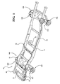
- FIG. 1 illustrates a vehicle, in this instance a pickup truck, 10 having an air suspension system 12.
- the air suspension system 12 is supported by a frame 14.
- the air suspensions system has four corner assemblies 16A-D located at each of the wheel 18 locations of the vehicle 10.
- the four corner assemblies 16A-D may be independently adjustable.
- Two corner assemblies 16A, B are located at the front wheel 18A, B corners of the vehicle 10 and two corner assemblies 16C, D are located at the rear wheel 18C, D corners of the vehicle.
- the air suspension system 12 includes an air supply unit 20 fluidly connected to the four corner assemblies 16A-D.
- the air supply unit 20 includes an electronic control unit 22, a compressor 24, a reservoir 26 and a valve block 30.
- the individual components of the air supply unit may be assembled together or supported on the vehicle at separate locations.
- the ECU 22 is located remote from the compressor 24, reservoir 26 and valve block 30.
- the individual components of the air supply unit 20 may be assembled together or supported on the vehicle 10 at separate locations.
- the ECU 22 is located remote from the compressor 24, reservoir 26 and valve block 30 (electrical connections not shown).
- the air suspensions system 12 may be an open loop system and the air supply unit may not include a reservoir 26.
- the air supply unit 20 is connected to the four corner assemblies 16A-D through the supply lines 28.
- the air suspension system 12 is a closed system.
- the valve block 30 is controlled by the ECU 22 to regulate the air supply between the compressor 24, the reservoir 26 and the four corner assemblies 16A-D.
- the valve block 30 may be a single unit defining multiple valves, multiple valves located together, or multiple valves at different locations. Additionally, the reservoir 26 may be a single or multiple tank assembly.
- the suspension system 12 may also be a system where the front and rear axle are separately adjustable, and does not necessarily require separate adjustment at each of the corner assemblies 16A-D. Therefore, the present invention may be used with any vehicle 10 that has an adjustable suspension system 12 having a park assist mode 35.
- the four corner assemblies 16A-D are adjustable to accommodate various driving conditions. Based upon the selected suspension mode the ECU 22 will regulate the air supply between the compressor 24, reservoir 26 and the four corner assemblies 16A-D to adjust the four corner assemblies 16A-D from the current positions to the desired positions. When lowering any of the corner assemblies 16A-D the excess air is sent to the reservoir 26 for storage. When raising any of the corner assemblies 16A-D the required air is sent from the reservoir 26 to the appropriate corner assembly 16A-D.
- the compressor 24 ensures that the air pressure within the system 12 is maintained at the desired level. Alternately, in the instance of an open system the excess air is released to the environment or pulled from the environment and pressurized as needed. The compressor 24 ensures that the air pressure within the system 12 is maintained at the desired level.
- the air suspension system 12 is adjusted at the direction of the vehicle operator by moving a selector, or when pre-determined operating conditions exist, e.g. the vehicle 10 accelerates above a certain speed and the suspension system 12 is lowered, when the vehicle 10 decelerates below a predetermined threshold the suspension system 12 raised. Therefore, the air suspension system 12 may be adjusted while the vehicle 10 is in motion.
- the front corner assemblies 16A, B may be adjustable together and the rear corner assemblies 16C, D may be adjustable together.
- the rear corner assemblies are adjusted to the new position first when the suspension system 12 is raised.
- the front corner assemblies 16A, B are adjusted to the new position first.
- each corner 16A-D could be adjusted separately or all corners 116A-D could be adjusted simultaneously.
- Figures 2-3 are schematic illustrations of a vehicle 10 with the air suspension system 12.
- Figure 2 illustrates the vehicle in a standard position 32.
- Figure 3 illustrates the vehicle in a park position 35.
- the air suspension system 12 is in a parked vehicle position corresponding to a lowering of the vehicle 10 height. Moving the vehicle 10 to the park position 35 is likely a two step process.
- the front corner assemblies 16A, B are moved together and the rear corner assemblies 16C, D are moved together.
- the present invention links the air suspension control 22 with a positioning system 25.
- the positioning system 25 may be an integrated, or non-integrated GPS unit, or may be another type of positioning system.
- the position system 25 is a GPS unit 25.
- the GPS unit 25 includes pre-defined favorite places, which are recognized by the GPS 25. The pre-defined favorite places may be manually selected by the driver, e.g. while the vehicle is in the favorite place the vehicle operator indicates to the GPS unit 25 that the current location is a favorite. Alternatively, the GPS unit 25 may recognize the location as a favorite based on history of the vehicle 10 parking in that location. Some variation may also be introduced into the favorite location to accommodate for small difference in parking location, e.g. different parking spaces within a frequently used parking lot.
- the vehicle 10 Once the vehicle 10 approaches such a favorite place (e.g. your driveway at home) it sends a request to the air suspension ECU 22 to lower the vehicle 10. Another option is, to add a speed dependency, to not lower down the vehicle 10 on such instances, as you only pass by a location without the intention of stopping.
- a favorite place e.g. your driveway at home
- Another option is, to add a speed dependency, to not lower down the vehicle 10 on such instances, as you only pass by a location without the intention of stopping.
- the GPS unit 25 may recognize when the vehicle 10 is approaching a final destination 37.
- the final destination 37 may be when approaching the end of a planned route entered in the GPS unit 25, a favorite place recorded in the GPS unit 25, or a frequently visited place.
- the GPS unit 25 reports to the ECU 22 for the suspensions system that the vehicle is approaching a final destination.
- the ECU 22 may also confirm the vehicle is approaching a final destination by comparing the vehicle 10 speed to a predetermined threshold.
- the signal may be sent when the vehicle 10 is a predetermined distance from the final destination, e.g. 500 ft.
- the predetermined distance may be selected based upon the amount of time a particular suspensions system 12 takes to move into a park mode 35 and other factors which, may include the predetermined speed threshold, or another selected speed for approximating how long it will take the vehicle to reach the final destination.
- One skilled in the art would be able to determine a desirable predetermined distance and predetermined speed threshold for a particular vehicle and suspension system.
- different predetermined distances may be selected for different suspensions modes, because the amount of time to move from one suspension mode into park mode may vary.
- the predetermined distance and/or predetermined threshold may be selectable by a vehicle operator.
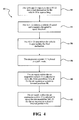
- the positioning system 25 reports to the ECU 22 that a final destination for the vehicle 10 is approaching, shown at 52.
- the ECU 22 detects a vehicle 10 speed and compares the speed to speed threshold, shown at 54.
- the ECU 22 may receive data from the vehicle sensors (not shown) to detect these and other conditions conditions. Based on this information the ECU 22 determines the vehicle is approaching the final destination, shown at 56 and selects a park mode, shown at 58.
- the ECU 22 controls the air supply within the air suspension system to move the front assemblies for the air suspension system to lowered positions 40, shown at 60 and to move the rear assemblies to lowered positions 42, shown at 62.
- the ECU 22 controls the air supply within the air suspension system 12 to move the two front corner assemblies 16A, B to the lowered positions 40 and the two rear corner to the lowered positions 42. That is, the ECU 22 directs air from the corner assemblies 16A- D tto move the corner assemblies 16A-D to the lowered positions 40, 42 by adjusting the valves within the valve block 30 to control air within the fluid lines 28.
- the front corner assemblies 16A, B move independently of the rear corner assemblies 16C, D.
- the ECU 22 may control the air supply unit 20 to complete movement of one end of the air suspensions system 12 prior to moving the other end of the air suspension system 12.
- the front corner assemblies 16A, B may be moved to the lowered positions 40 prior to controlling the air supply to move rear corner assemblies 16C, D to the lowered positions 42 when the vehicle 10 is travelling in a forward direction.
- Operation of the compressor 24 is also controlled by the ECU 22 to maintain air pressure within the air suspension system 12 at a desired level. Adjusting pressure within the system 12 may also be used to assist in controlling air flow to the desired location.
Landscapes
- Engineering & Computer Science (AREA)
- Mechanical Engineering (AREA)
- Vehicle Body Suspensions (AREA)
Applications Claiming Priority (2)
| Application Number | Priority Date | Filing Date | Title |
|---|---|---|---|
| US201361837822P | 2013-06-21 | 2013-06-21 | |
| US14/309,457 US9272596B2 (en) | 2013-06-21 | 2014-06-19 | GPS activated park mode for adjustable suspension systems |
Publications (2)
| Publication Number | Publication Date |
|---|---|
| EP2815903A2 true EP2815903A2 (fr) | 2014-12-24 |
| EP2815903A3 EP2815903A3 (fr) | 2015-04-22 |
Family
ID=51063267
Family Applications (1)
| Application Number | Title | Priority Date | Filing Date |
|---|---|---|---|
| EP20140173488 Ceased EP2815903A3 (fr) | 2013-06-21 | 2014-06-23 | Mode de stationnement activé par GPS pour systèmes de suspension réglable |
Country Status (2)
| Country | Link |
|---|---|
| US (1) | US9272596B2 (fr) |
| EP (1) | EP2815903A3 (fr) |
Cited By (2)
| Publication number | Priority date | Publication date | Assignee | Title |
|---|---|---|---|---|
| WO2020139609A1 (fr) * | 2018-12-26 | 2020-07-02 | Continental Automotive Systems, Inc. | Système d'amortissement dynamique de véhicule utilisant une suspension pneumatique |
| EP4699830A3 (fr) * | 2019-11-21 | 2026-04-15 | Tesla, Inc. | Suspension réglable pour véhicule |
Families Citing this family (6)
| Publication number | Priority date | Publication date | Assignee | Title |
|---|---|---|---|---|
| GB2528065B (en) * | 2014-07-08 | 2018-07-04 | Jaguar Land Rover Ltd | Vehicle suspension systems |
| DE102015000718A1 (de) * | 2015-01-21 | 2016-07-21 | Man Truck & Bus Ag | Verfahren und Vorrichtung zur Niveauregelung eines gefederten Fahrzeugaufbaus |
| DE102016116856A1 (de) | 2016-09-08 | 2018-03-08 | Knorr-Bremse Systeme für Nutzfahrzeuge GmbH | System und Verfahren zum Anpassen einer Höhe zumindest eines Teiles eines Nutzfahrzeuges |
| CN109969171A (zh) * | 2017-12-26 | 2019-07-05 | 罗伯特·博世有限公司 | 车库模式控制单元、控制系统和控制方法 |
| US20200158507A1 (en) * | 2018-11-19 | 2020-05-21 | GM Global Technology Operations LLC | Point of interest based vehicle settings |
| US11643098B1 (en) * | 2022-08-09 | 2023-05-09 | DEM Technologies LLC | Geolocation-based vehicle operation |
Family Cites Families (10)
| Publication number | Priority date | Publication date | Assignee | Title |
|---|---|---|---|---|
| US6111524A (en) * | 1995-11-09 | 2000-08-29 | Vehicle Enhancement Systems, Inc. | Systems and methods for identifying tractor/trailers and components thereof |
| JP2004345571A (ja) | 2003-05-23 | 2004-12-09 | Aisin Aw Co Ltd | 車両のサスペンション制御装置 |
| SE528864C2 (sv) | 2004-12-30 | 2007-02-27 | Volvo Lastvagnar Ab | Informationsbaserad styrning av chassihöjden hos ett fordon |
| US20060229811A1 (en) * | 2005-04-12 | 2006-10-12 | Herman Daren W | Vehicle navigation system |
| SE0501432L (sv) | 2005-06-17 | 2006-12-18 | Volvo Lastvagnar Ab | Höjdregleringssystem för ett fordon |
| US7987667B2 (en) * | 2006-11-28 | 2011-08-02 | Meier Diesel Filters, Inc. | GPS-activated exhaust filtration monitoring and control system |
| DE102007032970A1 (de) * | 2007-07-16 | 2009-01-22 | Knorr-Bremse Systeme für Nutzfahrzeuge GmbH | Steuereinrichtung für ein Druckluftsystem eines Fahrzeugs |
| TWI371576B (en) * | 2008-09-03 | 2012-09-01 | Compal Communications Inc | Navigation system capable of updating map data and method thereof |
| US9324195B2 (en) * | 2013-02-26 | 2016-04-26 | Polaris Industries Inc. | Recreational vehicle interactive, telemetry, mapping, and trip planning system |
| US20150019125A1 (en) * | 2013-07-15 | 2015-01-15 | Eduard Mazanec | Gps navigation directions display device, system, and process with points of interest |
-
2014
- 2014-06-19 US US14/309,457 patent/US9272596B2/en active Active
- 2014-06-23 EP EP20140173488 patent/EP2815903A3/fr not_active Ceased
Non-Patent Citations (1)
| Title |
|---|
| None |
Cited By (2)
| Publication number | Priority date | Publication date | Assignee | Title |
|---|---|---|---|---|
| WO2020139609A1 (fr) * | 2018-12-26 | 2020-07-02 | Continental Automotive Systems, Inc. | Système d'amortissement dynamique de véhicule utilisant une suspension pneumatique |
| EP4699830A3 (fr) * | 2019-11-21 | 2026-04-15 | Tesla, Inc. | Suspension réglable pour véhicule |
Also Published As
| Publication number | Publication date |
|---|---|
| EP2815903A3 (fr) | 2015-04-22 |
| US9272596B2 (en) | 2016-03-01 |
| US20140379214A1 (en) | 2014-12-25 |
Similar Documents
| Publication | Publication Date | Title |
|---|---|---|
| US9272596B2 (en) | GPS activated park mode for adjustable suspension systems | |
| US9272594B2 (en) | System and method of using air suspension to improve vehicle unloading | |
| US12350989B2 (en) | Vehicle active suspension control system and method | |
| CN102656081B (zh) | 用于对至少一个空气偏转器的位置进行优化的设备和方法 | |
| US20170080948A1 (en) | Vehicle mode adjusting system | |
| RU2493980C2 (ru) | Способ и модуль для определения опорных значений скорости для системы управления транспортным средством | |
| US8185269B2 (en) | Active suspension system for a vehicle and method of operating the same | |
| US20190171232A1 (en) | Methods and systems for semi-autonomous vehicular convoys | |
| CN103921645B (zh) | 在停放过程中促进车轮运动的悬挂控制系统 | |
| US9499140B2 (en) | Method for reducing jerk when completing an automatic braking maneuver | |
| EP2708389B1 (fr) | Remorque avec commande de niveau automatique | |
| US20160121666A1 (en) | Systems and methods for anticipatory tire pressure control | |
| US9211774B2 (en) | Vehicle load management | |
| CN104002811B (zh) | 用于运行具有组合的纵向和横向引导功能的机动车方的驾驶员辅助系统的方法 | |
| JP2005104171A (ja) | 車両用サスペンション制御システム及びサスペンション制御方法 | |
| US20150073658A1 (en) | Method and apparatus for operating a cushioning system for a motor vehicle | |
| EP2247465B1 (fr) | Procédé, système et produit de programme informatique pour commande de vitesse de véhicule automatisée | |
| US20150012167A1 (en) | Control device for an autonomous land vehicle | |
| KR20150066303A (ko) | 운전자의 주행 패턴을 반영하는 자율 주행 장치 및 그 방법 | |
| CN106985901A (zh) | 坡道驻车辅助 | |
| GB2475871A (en) | Navigation based function mapping for a vehicle | |
| US20170158016A1 (en) | Air suspension indvidual corner control to optimize traction | |
| CN108725266A (zh) | 调节车辆座椅的方法 | |
| JP2010064614A (ja) | 制動力制御装置 | |
| KR101737038B1 (ko) | 연비 디스플레이 기술을 융합한 스마트형 자동화클러치 제어 방법 |
Legal Events
| Date | Code | Title | Description |
|---|---|---|---|
| PUAI | Public reference made under article 153(3) epc to a published international application that has entered the european phase |
Free format text: ORIGINAL CODE: 0009012 |
|
| 17P | Request for examination filed |
Effective date: 20140623 |
|
| AK | Designated contracting states |
Kind code of ref document: A2 Designated state(s): AL AT BE BG CH CY CZ DE DK EE ES FI FR GB GR HR HU IE IS IT LI LT LU LV MC MK MT NL NO PL PT RO RS SE SI SK SM TR |
|
| AX | Request for extension of the european patent |
Extension state: BA ME |
|
| PUAL | Search report despatched |
Free format text: ORIGINAL CODE: 0009013 |
|
| AK | Designated contracting states |
Kind code of ref document: A3 Designated state(s): AL AT BE BG CH CY CZ DE DK EE ES FI FR GB GR HR HU IE IS IT LI LT LU LV MC MK MT NL NO PL PT RO RS SE SI SK SM TR |
|
| AX | Request for extension of the european patent |
Extension state: BA ME |
|
| RIC1 | Information provided on ipc code assigned before grant |
Ipc: B60G 17/015 20060101ALI20150318BHEP Ipc: B60G 17/019 20060101AFI20150318BHEP Ipc: B60G 17/016 20060101ALI20150318BHEP Ipc: B60G 17/04 20060101ALI20150318BHEP |
|
| R17P | Request for examination filed (corrected) |
Effective date: 20151022 |
|
| RBV | Designated contracting states (corrected) |
Designated state(s): AL AT BE BG CH CY CZ DE DK EE ES FI FR GB GR HR HU IE IS IT LI LT LU LV MC MK MT NL NO PL PT RO RS SE SI SK SM TR |
|
| STAA | Information on the status of an ep patent application or granted ep patent |
Free format text: STATUS: EXAMINATION IS IN PROGRESS |
|
| 17Q | First examination report despatched |
Effective date: 20180119 |
|
| STAA | Information on the status of an ep patent application or granted ep patent |
Free format text: STATUS: THE APPLICATION HAS BEEN REFUSED |
|
| 18R | Application refused |
Effective date: 20191115 |