EP2815980B1 - Zubehörmontage für einen Gasturbinenmotor - Google Patents
Zubehörmontage für einen Gasturbinenmotor Download PDFInfo
- Publication number
- EP2815980B1 EP2815980B1 EP14171741.3A EP14171741A EP2815980B1 EP 2815980 B1 EP2815980 B1 EP 2815980B1 EP 14171741 A EP14171741 A EP 14171741A EP 2815980 B1 EP2815980 B1 EP 2815980B1
- Authority
- EP
- European Patent Office
- Prior art keywords
- gas turbine
- turbine engine
- accessory
- frame
- mounting frame
- Prior art date
- Legal status (The legal status is an assumption and is not a legal conclusion. Google has not performed a legal analysis and makes no representation as to the accuracy of the status listed.)
- Active
Links
Images


Classifications
-
- F—MECHANICAL ENGINEERING; LIGHTING; HEATING; WEAPONS; BLASTING
- F02—COMBUSTION ENGINES; HOT-GAS OR COMBUSTION-PRODUCT ENGINE PLANTS
- F02C—GAS-TURBINE PLANTS; AIR INTAKES FOR JET-PROPULSION PLANTS; CONTROLLING FUEL SUPPLY IN AIR-BREATHING JET-PROPULSION PLANTS
- F02C7/00—Features, components parts, details or accessories, not provided for in, or of interest apart form groups F02C1/00 - F02C6/00; Air intakes for jet-propulsion plants
- F02C7/20—Mounting or supporting of plant; Accommodating heat expansion or creep
-
- B—PERFORMING OPERATIONS; TRANSPORTING
- B64—AIRCRAFT; AVIATION; COSMONAUTICS
- B64D—EQUIPMENT FOR FITTING IN OR TO AIRCRAFT; FLIGHT SUITS; PARACHUTES; ARRANGEMENT OR MOUNTING OF POWER PLANTS OR PROPULSION TRANSMISSIONS IN AIRCRAFT
- B64D27/00—Arrangement or mounting of power plants in aircraft; Aircraft characterised by the type or position of power plants
- B64D27/40—Arrangements for mounting power plants in aircraft
- B64D27/402—Arrangements for mounting power plants in aircraft comprising box like supporting frames, e.g. pylons or arrangements for embracing the power plant
-
- B—PERFORMING OPERATIONS; TRANSPORTING
- B64—AIRCRAFT; AVIATION; COSMONAUTICS
- B64D—EQUIPMENT FOR FITTING IN OR TO AIRCRAFT; FLIGHT SUITS; PARACHUTES; ARRANGEMENT OR MOUNTING OF POWER PLANTS OR PROPULSION TRANSMISSIONS IN AIRCRAFT
- B64D27/00—Arrangement or mounting of power plants in aircraft; Aircraft characterised by the type or position of power plants
- B64D27/40—Arrangements for mounting power plants in aircraft
- B64D27/404—Suspension arrangements specially adapted for supporting vertical loads
-
- B—PERFORMING OPERATIONS; TRANSPORTING
- B64—AIRCRAFT; AVIATION; COSMONAUTICS
- B64D—EQUIPMENT FOR FITTING IN OR TO AIRCRAFT; FLIGHT SUITS; PARACHUTES; ARRANGEMENT OR MOUNTING OF POWER PLANTS OR PROPULSION TRANSMISSIONS IN AIRCRAFT
- B64D27/00—Arrangement or mounting of power plants in aircraft; Aircraft characterised by the type or position of power plants
- B64D27/40—Arrangements for mounting power plants in aircraft
- B64D27/406—Suspension arrangements specially adapted for supporting thrust loads, e.g. thrust links
-
- B—PERFORMING OPERATIONS; TRANSPORTING
- B64—AIRCRAFT; AVIATION; COSMONAUTICS
- B64D—EQUIPMENT FOR FITTING IN OR TO AIRCRAFT; FLIGHT SUITS; PARACHUTES; ARRANGEMENT OR MOUNTING OF POWER PLANTS OR PROPULSION TRANSMISSIONS IN AIRCRAFT
- B64D29/00—Power-plant nacelles, fairings or cowlings
- B64D29/06—Attaching of nacelles, fairings or cowlings
-
- F—MECHANICAL ENGINEERING; LIGHTING; HEATING; WEAPONS; BLASTING
- F02—COMBUSTION ENGINES; HOT-GAS OR COMBUSTION-PRODUCT ENGINE PLANTS
- F02C—GAS-TURBINE PLANTS; AIR INTAKES FOR JET-PROPULSION PLANTS; CONTROLLING FUEL SUPPLY IN AIR-BREATHING JET-PROPULSION PLANTS
- F02C7/00—Features, components parts, details or accessories, not provided for in, or of interest apart form groups F02C1/00 - F02C6/00; Air intakes for jet-propulsion plants
- F02C7/32—Arrangement, mounting, or driving, of auxiliaries
-
- G—PHYSICS
- G01—MEASURING; TESTING
- G01M—TESTING STATIC OR DYNAMIC BALANCE OF MACHINES OR STRUCTURES; TESTING OF STRUCTURES OR APPARATUS, NOT OTHERWISE PROVIDED FOR
- G01M15/00—Testing of engines
- G01M15/14—Testing gas-turbine engines or jet-propulsion engines
-
- G—PHYSICS
- G01—MEASURING; TESTING
- G01M—TESTING STATIC OR DYNAMIC BALANCE OF MACHINES OR STRUCTURES; TESTING OF STRUCTURES OR APPARATUS, NOT OTHERWISE PROVIDED FOR
- G01M3/00—Investigating fluid-tightness of structures
- G01M3/02—Investigating fluid-tightness of structures by using fluid or vacuum
- G01M3/26—Investigating fluid-tightness of structures by using fluid or vacuum by measuring rate of loss or gain of fluid, e.g. by pressure-responsive devices, by flow detectors
- G01M3/28—Investigating fluid-tightness of structures by using fluid or vacuum by measuring rate of loss or gain of fluid, e.g. by pressure-responsive devices, by flow detectors for pipes, cables or tubes; for pipe joints or seals; for valves ; for welds
- G01M3/2846—Investigating fluid-tightness of structures by using fluid or vacuum by measuring rate of loss or gain of fluid, e.g. by pressure-responsive devices, by flow detectors for pipes, cables or tubes; for pipe joints or seals; for valves ; for welds for tubes
-
- Y—GENERAL TAGGING OF NEW TECHNOLOGICAL DEVELOPMENTS; GENERAL TAGGING OF CROSS-SECTIONAL TECHNOLOGIES SPANNING OVER SEVERAL SECTIONS OF THE IPC; TECHNICAL SUBJECTS COVERED BY FORMER USPC CROSS-REFERENCE ART COLLECTIONS [XRACs] AND DIGESTS
- Y02—TECHNOLOGIES OR APPLICATIONS FOR MITIGATION OR ADAPTATION AGAINST CLIMATE CHANGE
- Y02T—CLIMATE CHANGE MITIGATION TECHNOLOGIES RELATED TO TRANSPORTATION
- Y02T50/00—Aeronautics or air transport
- Y02T50/60—Efficient propulsion technologies, e.g. for aircraft
Definitions
- the present invention relates to an accessory mounting for a gas turbine engine and in particular to an accessory mounting arrangement for a turbofan gas turbine engine.
- the accessory mounting frame is subject to vibrations and/or other loads and these vibrations and/or other loads may result in damage to the accessory mounting frame. If the damage to the accessory mounting frame were to remain undetected and therefore unrepaired, or replaced, it may lead to a failure of one or more portions or the whole of the accessory mounting frame.
- the accessory mounting frame carries all the accessories for the gas turbine engine and a failure of the accessory mounting frame may lead to loss of operation of one or more of the accessories, e.g. may lead to a loss of hydraulic supply, a loss of fuel supply, a loss of lubricant supply or a loss of electrical power which may result in a failure of the gas turbine engine.
- the present invention seeks to provide a novel arrangement for detecting damage to the accessory mounting frame which reduces or overcomes the above mentioned problem.
- US 2978209A discloses a gas turbine assembly according to the state of the art.
- the present invention provides a gas turbine engine assembly connected to a pylon structure for mounting the gas turbine engine to an aircraft, the assembly having a frame supporting at least one accessory independently of the gas turbine engine, the frame being attached to the pylon at forward and rearward engine mounting locations, the frame comprising at least one hollow tube, the at least one hollow tube being fluid tight, the at least one hollow tube being evacuated or containing pressurised fluid and a pressure sensor being arranged to detect a change in the pressure in the at least one hollow tube to determine if there is a leak in the at least one hollow tube and hence if the frame is damaged.
- the frame may provide a direct load path between the at least one accessory and one or more forward and rearward engine mounting locations of the gas turbine engine.
- Anti-vibration mounts may be provided between the frame and the forward and/or rearward mount engine mounting locations of the gas turbine engine.
- Anti-vibration mounts may be provided between the frame and the at least one accessory.
- the frame may comprise at least one jointed strut for providing axial movement for compensation of thermal expansion.
- the frame may further comprise a ring structure for accessory mounting purposes, the ring structure being arranged coaxially with the axis of the engine.
- the ring structure may be provided by a plurality of curved segments welded or bolted together.
- An integral mounting plate may be provided to interface between the pylon structure and the frame.
- the frame may comprise a front support and a rear support.
- the front support may have two front struts arranged on opposite sides of the engine and the rear support may have two rear struts arranged on opposite sides of the engine.
- the at least one accessory may be an accessory gearbox, a hydraulic pump, an oil pump, a fuel pump, an electrical generator or an electrical motor.
- the assembly may have an accessory gearbox and the accessory gearbox may be connected to the front mount by the front support and being connected to the rear mount by the rear support.
- An axial link may be provided between a front structure and the accessory gearbox or the frame structure to reduce unwanted axial movement of the accessory gearbox or the frame structure.
- the assembly may having an accessory gearbox, the frame comprising a ring structure arranged coaxially with the axis of the engine, the ring structure being connected to the rear mount by the rear support, the accessory gearbox being connected to the front mount by the front support and the accessory gearbox being connected to the ring structure by at least one additional strut.
- the at least one additional strut may be connected to the front support.
- a nacelle may surround the core engine wherein the at least one accessory is positioned within the nacelle.
- the nacelle may have an opening in a forward position of the nacelle to supply cooling air over the accessories.
- the nacelle may have an opening in a rearward position of the nacelle to discharge cooling air out of nacelle.
- the nacelle may be an inner nacelle separating the core engine from a bypass duct.
- the frame may define a plurality of fluid tight chambers, each chamber being evacuated or containing pressurised fluid and each chamber having a pressure sensor arranged to detect a change in the pressure in the associated chamber to determine if there is a leak in the associated chamber and hence if the frame is damaged.
- the frame may comprise a plurality of hollow tubes, each hollow tube being fluid tight and defining a respective chamber, each hollow tube being evacuated or containing pressurised fluid and each hollow tube having a pressure sensor arranged to detect a change in the pressure in the associated hollow tube to determine if there is a leak in the associated hollow tube and hence if the frame is damaged.
- the pressurised fluid may be an inert gas.
- the inert gas may be nitrogen.
- a turbofan gas turbine engine 10 as shown in figure 1 , comprises, in axial flow series, an air intake 1, a propulsive fan 2, an intermediate pressure compressor 3, a high pressure compressor 4, combustion equipment 5, a high pressure turbine 6, an intermediate pressure turbine 7, a low pressure turbine 8 and an exhaust nozzle 9. Air entering the air intake 1 is accelerated by the fan 2 to produce two air flows. A first air flow is supplied into the intermediate pressure compressor 3 and a second air flow 59 that passes over an inner nacelle 40 and though a bypass duct which provides propulsive thrust. The intermediate pressure compressor 3 compresses the air flow directed into it before delivering the air to the high pressure compressor 4 where further compression takes place.
- Compressed air exhausted from the high pressure compressor 4 is directed into the combustion equipment 5, where it is mixed with fuel that is injected from fuel injectors 61 and the mixture is combusted.
- the resultant hot combustion products expand through and thereby drive the high, intermediate and low pressure turbines 6, 7 and 8 respectively before this flow is exhausted as a core stream 60 through the nozzle 9 to provide additional propulsive thrust.
- the high, intermediate and low pressure turbines 6, 7 and 8 respectively drive the high and intermediate pressure compressors 4 and 3 and the fan 2 by suitable interconnecting shafts: high pressure shaft 68, intermediate pressure shaft 67 and low pressure shaft 66.
- a flow of cooling air 58 for the accessories enters the accessory mounting zone through an opening at the front, upstream end, of the inner nacelle 40 and is exhausted through an opening into the bypass air stream 59 at the rear, downstream end, of the inner nacelle 40 or is exhausted into the core flow 60 at the rear, downstream end, of the turbofan gas turbine engine 10 upstream of the exhaust nozzle 9.
- the turbofan gas turbine engine 10 is mounted to the aircraft structure via a pylon 14 which locates on the turbofan gas turbine engine 10 at a front mount 16 and a rear mount 18.
- the mounts 16 and 28 carry the weight of the turbofan gas turbine engine 10 and transfer thrust loads from the turbofan gas turbine engine 10 through the pylon 14 to the aircraft structure.
- the front of the pylon 14 is attached to the front mount 16 through a front attachment bracket 20 which is integral with or bolted to the pylon 14.
- the rear of the pylon 14 is mounted to the rear engine mount 18 through a rear attachment bracket 22 and an engine link 24 which permits axial movement of the turbofan gas turbine engine 10 relative to the rear attachment bracket 22.
- the front mount 16 is provided on the front frame 54 in this example, but alternatively may be provided on the fan casing.
- the front mount 16 and the rear mount 18 may both be provided on the core engine casing or the front mount 16 is provided on the fan casing and the rear mount 18 is provided on the core engine casing.
- the accessory mounting frame 26 is also attached to the pylon 14 by mounts 28, which may be anti-vibration mounts 49.
- the accessory mounting frame 26 of Figure 1 has two front struts 30 that extend from the front attachment bracket 20 and join to respective rear struts 32 that extend from the rear attachment bracket 22. It will be appreciated that one arrangement of front and rear struts 30 and 32 passes to one side of the core engine and that a corresponding arrangement of front and rear struts 30 and 32 is provided on the opposite side of the core engine. Although the front and rear struts 30, 32 are shown as being straight it may be necessary to use curved struts that bow around the core engine.
- Each rear strut 32 may be attached to the rear attachment bracket 22 through a swing link 34 which permits axial movement of the rear strut 32 as required by, for example, thermal growth.
- the front and rear struts 30 and 32 together form a "V" arrangement and join at an accessory 35, in this case the accessory gearbox.
- the front and rear struts 30 and 32 are mounted to the accessory gearbox by one or more hinge mounts 36.
- the accessory gearbox 35 provides power to other engine accessories such as an electrical generator, hydraulic pumps, oil pumps, fuel pumps etc.
- the electrical generator may be a starter/generator such that the electrical generator may be used as an electrical motor to start the turbofan gas turbine engine 10.
- the accessory gearbox 35 can be driven by a radial and an axial drive train, e.g. from the low speed drive train 63 which is driven by the low pressure shaft 66.
- the accessory gearbox can be further driven by a radial drive train e.g. by the high speed drive train 64 which is driven by the high pressure shaft 68.
- These drive trains have preferably one or more interconnections or couplings (e.g. spline connections) 65 to withstand movement of the accessory gearbox 35.
- the rear strut 32 has additional frame section 38 mounted to it.
- the additional frame section 38 advantageously provides additional locations for mounting of further accessories 50.
- the shape of the additional frame section 38 may be selected so that the further accessories 50 can be optimally located in order to reduce the length of any mounting brackets, drive trains or circuitry to the further accessories 50 or to ensure all the accessories 50 can fit within the inner nacelle line 40, which can be a congested volume.
- Exemplary accessories 50 which may be mounted are generators e.g. starter generators, pumps, gearboxes, brackets, cables, sensors, and wiring.
- the location of the components may be selected to provide good access for maintenance.
- the accessories 35, 50 are arranged within an accessory mounting zone defined between the inner nacelle 40 and a core engine casing 12.
- the mounts 28, 36 are preferably anti vibration mounts which may beneficially decouple the accessories 35, 50 from the engine core vibrations.
- the mounts 28, 36 may be selected to further reduce the vibration response of the accessory mounting frame 26 and finally the vibration input to the accessories 35, 50.
- the corresponding vibration loads could, if not damped, lead to foot-point excitation of an accessory bracket and early failure of the bracket or accessory.
- Engine thrust links 52 are provided, one on each side of the engine (preferably one arranged on the left of the engine and one arranged on the right of the engine) and are located between the rear attachment bracket 22 and the front frame 54. No accessories are mounted to these links.
- the accessory mounting frame 26 comprises at least one hollow tube and the front struts 30, the rear struts 32 and the additional frame section 38 comprise hollow tubes.
- the hollow tubes of the accessory mounting frame 26 are joined together so that the hollow tubes of the accessory mounting frame define at least one fluid tight, leak free, chamber when in the manufactured condition.
- the hollow tubes of the accessory mounting frame 26 are joined together by a suitable manufacturing process, e.g. welding, brazing etc.
- Pressurised fluid e.g. air
- fluid, air is supplied into the chamber within the accessory mounting frame 26 or fluid, air, is evacuated from the chamber within the accessory mounting frame 26 when the accessory mounting frame is manufactured or during maintenance of the gas turbine engine.
- the pressurised fluid, air may be supplied from a gas bottle or the pressurised fluid, air, may be supplied from another suitable source of pressurised air, e.g. a compressor.
- the pressurised fluid may be supplied into the chamber within the accessory mounting frame through a respective non-return valve 74.
- the fluid may be evacuated from the chamber in the accessory mounting frame 26 by a vacuum pump.
- the accessory mounting frame 26 is sealed and a pressure sensor 76 is provided to monitor the pressure in the chamber in the accessory mounting frame 26. If the pressure sensor 76 indicates that the pressure in the chamber in the accessory mounting frame 26 is below a predetermined level that was provided in the accessory mounting frame 26 this provides an indication that the accessory mounting frame 26 is damaged or there is a fault, e.g. there is a crack, due to leakage of fluid out of the hollow tubes of the accessory mounting frame 26.
- the pressure sensor 76 indicates that the pressure in the chamber in the accessory mounting frame 26 is above a predetermined level that was provided in the accessory mounting frame 26 this is an indication that the accessory mounting frame 26 is damaged or there is a fault, e.g. there is a crack, due to leakage of air into the hollow tubes of the accessory mounting frame 26.
- the pressure sensor 76 may be a digital pressure sensor or an analogue pressure sensor.
- the use of the pressure sensor enables an early warning that there is a fault with the accessory mounting frame 26 during routine maintenance inspections of the gas turbine engine. It is important to detect impending failure of the accessory mounting frame 26 because the accessory mounting frame 26 carries all the accessories 35, 50 for the gas turbine engine and a failure of the accessory mounting frame 26 may lead to loss of operation of one or more of the accessories 35, 50, e.g. could lead to a loss of hydraulic supply, a loss of fuel supply, a loss of lubricant supply or a loss of electrical power which may result in a failure of the gas turbine engine.
- an advantage of the present invention is that the use of the pressure sensor 76 enables an early warning that there is fault, a crack, at the joint, weld or braze, between the hollow tubes of the mounting frame 26 or indeed actually in the hollow tubes of the mounting frame 26.
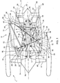
- FIG. 2 depicts a turbofan gas turbine engine with the inner nacelle removed.
- the turbofan gas turbine engine is mounted to the airframe via a pylon 14 that is mounted to the main aircraft structure through lugs 15 at the midpoint and aft end of the pylon 14.
- the pylon 14 has a front mounting bracket 20 which is attached to the front frame structure 54 at a front mount 16 and a rear mounting bracket 22 attached to a rear mount 18 on the turbine casing or engine rear structure 55 via links 53 at the rear of the turbofan gas turbine engine.
- the pylon 14 is positioned at the top of the turbofan gas turbine engine and struts 30, 32 extend down from the pylon 14 to form a frame 26 for mounting accessories.
- Two front struts 30 are provided, one for each side of the core engine. These front struts 30 are substantially vertical and diverge from the pylon 14 and are mounted to respective lugs 42 on the accessory gearbox 35, one lug on each side of the core engine.
- Two rear struts 32 are provided, one for each side of the core engine. These rear struts 32 are angled forwards and diverge from the pylon 14 and are mounted to respective rear lugs 44 on the accessory gearbox 35, one lug on each side of the core engine.
- the accessory gearbox 35 is securely mounted to the pylon 14 but an optional axial link 46 may be provided between the front frame structure 54 and the accessory gearbox 35 to reduce unwanted axial movement of the accessory gearbox 35. Further accessories and dressings 50 may be mounted off the accessory gearbox 35 or the accessory mounting frame 26 directly.
- a further support strut 48 may be provided between the front strut 30 and the rear strut 32 onto which additional accessories 50 may be mounted.
- an engine thrust link 52 is located between the rear attachment bracket 22 and the front frame structure 54. No accessories are mounted to this thrust link 52.
- the engine thrust link 52 and optional axial link 46 at one side of the engine are secured to the front frame structure 54 by brackets at substantially the same point on the front frame structure 54.
- Anti-vibration mounts 49 may be used between the front struts 30 and the front attachment bracket 20 and between the rear struts 32 and the rear attachment bracket 22.
- the vibration mounts 49 permit the engine loads or eigenfrequency behaviours of the turbofan gas turbine engine and engine casing structure to be decoupled from the accessory units 35, 50. Beneficially, the effects of whole engine vibration need not be considered to a high extent for the environment of the accessories.
- Applied vibration effects of the accessory mounting frame 26 may be adjusted by the shape of the accessory mounting frame 26 and the attachment points to the pylon 14.
- the anti-vibration mounts 49 where used, have a different damping characteristic to the rest of the accessory mounting frame 26 and may be made from softer materials such as high temperature elastomeric or composite metal assemblies with implemented spring effects.
- the attachment points at the rear of the frame can include swing links which mitigate the effects of thermal expansion of the engine casing or other components.
- the accessory gearbox 35 is driven by the low speed drive train 63 and/or is driven by a high speed drive train 64.
- Both drive trains should be covered by covers 62 for protection purpose and to avoid oil and heat contamination between the drive trains and adjacent hardware (e.g. accessories 50).
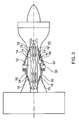
- Figure 3 is a simplified top view of the embodiment of Figure 2 . Some details shown in figure 2 , such as the thrust struts 52, are omitted for clarity.
- the accessory gearbox 35 is joined to the pylon 14, in between the core engine casings 12, by symmetrically arranged front struts 30 and symmetrically arranged rear struts 32.
- the front and rear struts 30 and 32 respectively diverge from the pylon 14 with the spacing at the distal ends being determined by the size of the accessory 35. It will be appreciated that this spacing may be provided by a spacing strut to which the accessory may be mounted. In this arrangement the front and rear struts 30 and 32 may not be directly attached to the accessory 35.
- Main accessory support structures 48 are attached to these struts 30 and 32 to further stiffen up the whole structure and provide preferred attachment place for further accessories 50.
- the accessory mounting frame 26 shown in Figures 2 and 3 also comprises at least one hollow tube and the front struts 30, the rear struts 32 and the further support struts 48 comprise hollow tubes.
- the hollow tubes of the accessory mounting frame 26 are joined together so that the hollow tubes of the accessory mounting frame define at least one fluid tight, leak free, chamber when in the manufactured condition.
- the hollow tubes of the accessory mounting frame 26 are joined together by a suitable manufacturing process, e.g. welding, brazing etc. Pressurised fluid, e.g. air, is supplied into the chamber within the accessory mounting frame 26 or fluid, air, is evacuated from the chamber within the accessory mounting frame 26.
- the pressurised fluid, air may be supplied from a gas bottle or the pressurised fluid, air, may be supplied from another suitable source of pressurised air, e.g. a compressor.
- the pressurised fluid may be supplied into the chamber within the accessory mounting frame through a respective non-return valve 74.
- the fluid may be evacuated from the chamber in the accessory mounting frame 26 by a vacuum pump.
- the accessory mounting frame 26 is sealed and a pressure sensor 76 is provided to monitor the pressure in the chamber in the accessory mounting frame 26. If the pressure sensor 76 indicates that the pressure in the chamber in the accessory mounting frame 26 is below a predetermined level that was provided in the accessory mounting frame 26 this provides an indication that the accessory mounting frame 26 is damaged or there is a fault, e.g. there is a crack, due to leakage of fluid out of the hollow tubes of the accessory mounting frame 26.
- the pressure sensor 76 indicates that the pressure in the chamber in the accessory mounting frame 26 is above a predetermined level that was provided in the accessory mounting frame 26 this is an indication that the accessory mounting frame 26 is damaged or there is a fault, e.g. there is a crack, due to leakage of air into the hollow tubes of the accessory mounting frame 26.
- the pressure sensor 76 may be a digital pressure sensor or an analogue pressure sensor.
- the use of the pressure sensor enables an early warning that there is a fault with the accessory mounting frame 26 during routine maintenance inspections of the gas turbine engine. It is important to detect impending failure of the accessory mounting frame 26 because the accessory mounting frame 26 carries all the accessories 35, 50 for the gas turbine engine and a failure of the accessory mounting frame 26 may lead to loss of operation of one or more of the accessories 35, 50, e.g. could lead to a loss of hydraulic supply, a loss of fuel supply, a loss of lubricant supply or a loss of electrical power which may result in a failure of the gas turbine engine.
- an advantage of the present invention is that the use of the pressure sensor 76 enables an early warning that there is fault, a crack, at the joint, weld or braze, between the hollow tubes of the mounting frame 26 or indeed actually in the hollow tubes of the mounting frame 26.
- each of the front struts 30 comprises a hollow tube
- each of the rear struts 32 comprises a hollow tube
- each of the further support struts 48 comprises a hollow tube.
- Each of the tubes defines a respective chamber in the accessory mounting frame and each chamber is evacuated, or pressurised, and the pressure in each chamber of the accessory mounting frame 26 is monitored using a respective pressure sensor 76. If a pressure sensor 76 indicates that the pressure in the associated chamber within the accessory mounting frame 26 is below, or above, the predetermined level that was provided in that chamber within the accessory mounting frame 26 this provides an indication that the portion of the accessory mounting frame 26 defining that chamber is damaged or there is a fault, e.g. there is a crack, due to leakage of fluid out of, or into, that particular chamber within hollow tubes of the accessory mounting frame 26.
- FIG. 4 depicts an alternative embodiment, where the same reference numerals are used for the same components of the previous embodiments.
- the accessory mounting frame 26 of the turbofan gas turbine engine assembly is provided with a hooped accessory support structure 48 which is coaxially arranged with the engine axis.
- the hooped accessory support structure 48 may be provided as separate elements which are hinged, bolted, welded or otherwise secured together so that it can be assembled around the engine.
- the hooped accessory support structure 48 has the primary function of carrying a number of accessories 50 other than the main accessory gearbox 35. Beneficially by mounting accessories 50 in this way it is possible to isolate the accessories 50 attached to the hooped accessory support structure 48 from vibrations and loads from both the accessory gearbox 35 and the engine.
- the accessory mounting frame 26 again comprises front struts 30 and rear struts 30.
- Each front strut 30 extends from the front mount 16 to the accessory gearbox 35 and each rear strut 32 extends from the rear mount 18 to the hooped accessory support structure 48 on the respective sides of the turbofan gas turbine engine.
- Additional struts 47 extend from the front frame structure 54 to the hooped accessory support structure 48 on respective sides of the turbofan gas turbine engine. Each additional strut 47 intersects a respective one of the front struts 30.
- Engine thrust links 52 are located between the rear attachment bracket 22 and the front frame structure 54.
- Optional axial links 46 are provided between the front frame structure 54 and the accessory gearbox 35 to reduce unwanted axial movement of the accessory gearbox 35.
- the engine thrust link 52, the optional axial link 46 and the additional strut 47 at one side of the engines are secured to the front frame structure 54 by brackets at substantially the same point on the front frame structure 54.
- the accessory mounting frame 26 shown in Figure 4 also comprises at least one hollow tube and the front struts 30, the rear struts 32, the additional struts 47 and the hooped accessory support structure 48 comprise hollow tubes.
- the hollow tubes of the accessory mounting frame 26 are joined together so that the hollow tubes of the accessory mounting frame define at least one fluid tight, leak free, chamber when in the manufactured condition, e.g. each front strut 30 is joined to the associated rear strut 32 via associated additional strut 47 and hooped accessory support structure 48.
- the hollow tubes of the accessory mounting frame 26 are joined together by a suitable manufacturing process, e.g. welding, brazing etc. Pressurised fluid, e.g.
- air is supplied into the chamber within the accessory mounting frame 26 or fluid, air, is evacuated from the chamber within the accessory mounting frame 26.
- the pressurised fluid, air may be supplied from a gas bottle or the pressurised fluid, air, may be supplied from another suitable source of pressurised air, e.g. a compressor.
- the pressurised fluid may be supplied into the chamber within the accessory mounting frame through a respective non-return valve 74.
- the fluid may be evacuated from the chamber in the accessory mounting frame 26 by a vacuum pump.
- the accessory mounting frame 26 is sealed and a pressure sensor 76 is provided to monitor the pressure in the chamber in the accessory mounting frame 26. If the pressure sensor 76 indicates that the pressure in the chamber in the accessory mounting frame 26 is below a predetermined level that was provided in the accessory mounting frame 26 this provides an indication that the accessory mounting frame 26 is damaged or there is a fault, e.g. there is a crack, due to leakage of fluid out of the hollow tubes of the accessory mounting frame 26.
- the pressure sensor 76 indicates that the pressure in the chamber in the accessory mounting frame 26 is above a predetermined level that was provided in the accessory mounting frame 26 this is an indication that the accessory mounting frame 26 is damaged or there is a fault, e.g. there is a crack, due to leakage of air into the hollow tubes of the accessory mounting frame 26.
- the pressure sensor 76 may be a digital pressure sensor or an analogue pressure sensor.
- the use of the pressure sensor enables an early warning that there is a fault with the accessory mounting frame 26 during routine maintenance inspections of the gas turbine engine. It is important to detect impending failure of the accessory mounting frame 26 because the accessory mounting frame 26 carries all the accessories 35, 50 for the gas turbine engine and a failure of the accessory mounting frame 26 may lead to loss of operation of one or more of the accessories 35, 50, e.g. could lead to a loss of hydraulic supply, a loss of fuel supply, a loss of lubricant supply or a loss of electrical power which may result in a failure of the gas turbine engine.
- an advantage of the present invention is that the use of the pressure sensor 76 enables an early warning that there is fault, a crack, at the joint, weld or braze, between the hollow tubes of the mounting frame 26 or indeed actually in the hollow tubes of the mounting frame 26.
- the hollow tubes of the accessory mounting frame 26 are joined together to form a number of chambers in the accessory mounting frame 26 and each chamber is evacuated, or pressurised, and the pressure in each chamber of the accessory mounting frame 26 is monitored using a respective pressure sensor 76. If a pressure sensor 76 indicates that the pressure in the associated chamber within the accessory mounting frame 26 is below, or above, the predetermined level that was provided in that chamber within the accessory mounting frame 26 this provides an indication that the portion of the accessory mounting frame 26 defining that chamber is damaged or there is a fault, e.g. there is a crack, due to leakage of fluid out of, or into, that particular chamber within hollow tubes of the accessory mounting frame 26.
- each hollow tube, each of the front struts 30, each of the rear struts 32, each of the additional struts 47 and the hooped accessory support structure 48 define its own respective chamber and has a respective pressure sensor 76.
- the hollow tubes of the front struts 30, the rear struts 32, the additional struts 47 and the hooped accessory support structure 48 may be arranged to define a single chamber with a single pressure sensor.
- an accessory mounting frame can be removed from the engine assembly without having to remove the engine from the pylon structure.
- Accessories may be pre-mounted on the accessory mounting frame prior to the accessory mounting frame being mounted to the front and / or rear mounts. This is advantageous as it can speed up repair and replacement of accessories.
- the provision of the pressure sensors to detect changes in the pressure within the chamber, or chambers, defined by the hollow tube, or hollow tubes, of the accessory mounting frame enables early detection of damage to the accessory mounting frame and enabling the accessory mounting frame to be repaired or replaced.
- the turbofan gas turbine engine is mounted to the pylon 14 by engine rear mount attachment struts 53.
- a fail safe swing link 51 further connects the turbofan gas turbine engine 10 via the rear attachment bracket 22 to the pylon 14 to prevent the turbofan gas turbine engine becoming detached from the pylon 14 should the engine rear mount attachment struts fail for any reason.
- the frame maybe used to stiffen the engine main structure.
- the vibration isolation effect described before may be affected, the rotor tip clearance will be improved and the material thickness of the core engine casings can be reduced in thickness.
- an inert gas is a gas which will not react with the hollow tubes, for example nitrogen, helium, argon, neon etc. These gases may also be supplied into the hollow tubes of the accessory mounting frame from suitable gas bottles.
- turbofan gas turbine engine it may be possible to provide a frame according to the present invention on a turbo-shaft gas turbine engine, a turbo-propeller gas turbine engine or a turbojet gas turbine engine.
- present invention has been described with reference to a three shaft engine gas turbine engine it is equally applicable to a two shaft gas turbine engine and to a single shaft gas turbine engine.
Landscapes
- Engineering & Computer Science (AREA)
- Chemical & Material Sciences (AREA)
- Combustion & Propulsion (AREA)
- Aviation & Aerospace Engineering (AREA)
- Mechanical Engineering (AREA)
- General Engineering & Computer Science (AREA)
- Physics & Mathematics (AREA)
- General Physics & Mathematics (AREA)
- Control Of Turbines (AREA)
- Connection Of Motors, Electrical Generators, Mechanical Devices, And The Like (AREA)
- Structures Of Non-Positive Displacement Pumps (AREA)
Claims (15)
- Gasturbinentriebwerkanordnung, verbindbar mit einer Pylonstruktur (14) zum Befestigen des Gasturbinentriebwerks (10) an einem Flugzeug, wobei die Anordnung einen Rahmen (26) aufweist, der mindestens ein Zubehörteil (35, 50) unabhängig von dem Gasturbinentriebwerk (10) stützt, wobei der Rahmen (26) an dem Pylon (14) an einer vorderen und hinteren Triebwerkbefestigungsposition (16, 18) anbringbar ist, wobei der Rahmen (26) mindestens eine hohle Röhre (30, 32, 38) umfasst, wobei die mindestens eine hohle Röhre (30, 32,38) fluiddicht ist, dadurch gekennzeichnet, dass die mindestens eine hohle Röhre (30, 32, 38) evakuiert wird oder mit Druck beaufschlagtes Fluid und einen Drucksensor (76) enthält, der derart angeordnet ist, dass er eine Veränderung des Drucks in der mindestens einen hohlen Röhre (30, 32, 38) erkennt, um zu bestimmen, ob ein Leck in der mindestens einen hohlen Röhre (30, 32, 38) existiert und ob somit der Rahmen (26) beschädigt ist.
- Gasturbinentriebwerkanordnung nach Anspruch 1, wobei der Rahmen (26) ferner eine Ringstruktur (48) zu Zubehörteil- (35, 50) Befestigungszwecken umfasst, wobei die Ringstruktur (48) koaxial zu der Achse des Treibwerks (10) angeordnet ist.
- Gasturbinentriebwerkanordnung nach Anspruch 1 oder Anspruch 2, wobei der Rahmen (26) eine vordere Stütze und eine hintere Stütze umfasst, wobei die vordere Stütze zwei vordere Streben (30) aufweist, die an entgegengesetzten Seiten des Triebwerks (10) angeordnet sind, und die hintere Stütze zwei hintere Streben (32) aufweist, die an entgegengesetzten Seiten des Triebwerks (10) angeordnet sind.
- Gasturbinentriebwerkanordnung nach einem der Ansprüche 1 bis 3, wobei das mindestens eine Zubehörteil (35, 50) ein Hilfsgetriebe, eine Hydraulikpumpe, eine Ölpumpe, eine Kraftstoffpumpe, ein elektrischer Generator oder ein elektrischer Motor ist.
- Gasturbinentriebwerkanordnung nach Anspruch 3, wobei die Anordnung ein Zusatzgetriebe (35) aufweist, wobei das Zusatzgetriebe (35) mit der vorderen Befestigung (16) über die vordere Stütze verbunden ist und mit der hinteren Befestigung (18) über die hintere Stütze befestigt ist.
- Gasturbinentriebwerkanordnung nach Anspruch 3, wobei die Anordnung ein Zusatzgetriebe (35) aufweist, wobei der Rahmen (26) eine Ringstruktur (48) umfasst, die koaxial zu der Achse des Triebwerks (10) angeordnet ist, wobei die Ringstruktur (48) mit der hinteren Befestigung (18) über die hintere Stütze verbunden ist, wobei das Zusatzgetriebe (35) mit der vorderen Befestigung (16) über die vordere Stütze verbunden ist und das Zusatzgetriebe (35) mit der Ringstruktur (48) über mindestens eine zusätzliche Strebe (47) verbunden ist.
- Gasturbinentriebwerkanordnung nach einem der Ansprüche 1 bis 6 mit einer Gondel (40), die das Kerntriebwerk (3, 4, 5, 6, 7, 8) umgibt, wobei das mindestens eine Zubehörteil (35, 50) innerhalb der Gondel (40) angeordnet ist.
- Gasturbinentriebwerkanordnung nach Anspruch 7, wobei die Gondel (40) eine Öffnung (41) in einer vorderen Position der Gondel (40) aufweist, um Kühlluft über die Zubehörteile (35, 50) zuzuführen.
- Gasturbinentriebwerkanordnung nach Anspruch 7 oder Anspruch 8, wobei die Gondel (40) eine Öffnung in einer hinteren Position der Gondel (40) aufweist, um Kühlluft aus der Gondel (40) abzulassen.
- Gasturbinentriebwerkanordnung nach einem der Ansprüche 7 bis 9, wobei die Gondel (40) eine innere Gondel ist, die das Kerntriebwerk (3, 4, 5, 6, 7, 8) von einem Bypasskanal trennt.
- Gasturbinentriebwerkanordnung nach einem der Ansprüche 1 bis 10, wobei eine Mehrzahl von Zubehörteilen (35, 50) existiert.
- Gasturbinentriebwerkanordnung nach einem der Ansprüche 1 bis 11, wobei der Rahmen (26) eine Mehrzahl fluiddichter Kammern definiert, wobei jede Kammer evakuiert wird oder mit Druck beaufschlagtes Fluid enthält und jede Kammer einen Drucksensor (76) aufweist, der derart angeordnet ist, dass er eine Veränderung des Drucks in der zugeordneten Kammer erkennt, um zu bestimmen, ob ein Leck in der zugeordneten Kammer existiert und ob der Rahmen somit (26) beschädigt ist.
- Gasturbinentriebwerkanordnung nach einem der Ansprüche 1 bis 12, wobei der Rahmen (26) eine Mehrzahl hohler Röhren (30, 32, 38) umfasst, wobei jede hohle Röhre (30, 32, 38) fluiddicht ist und eine entsprechende Kammer definiert, wobei jede hohle Röhre (30, 32, 38), evakuiert wird oder ein mit Druck beaufschlagtes Fluid enthält und jede hohle Röhre (30, 32, 38) einen Drucksensor (76) aufweist, der derart angeordnet ist, dass er eine Veränderung des Drucks in der zugeordneten hohlen Röhre erkennt (30, 32, 38), um zu bestimmen, ob ein Leck in der zugeordneten hohlen Röhre (30, 32, 38) existiert und der Rahmen (26) somit beschädigt ist.
- Gasturbinentriebwerkanordnung nach einem der Ansprüche 1 bis 13, wobei das mit Druck beaufschlagte Fluid ein Inertgas ist.
- Gasturbinentriebwerkanordnung nach Anspruch 14, wobei das Inertgas Stickstoff ist.
Applications Claiming Priority (1)
| Application Number | Priority Date | Filing Date | Title |
|---|---|---|---|
| GB201311072A GB201311072D0 (en) | 2013-06-21 | 2013-06-21 | An accessory mounting for a gas turbine engine |
Publications (2)
| Publication Number | Publication Date |
|---|---|
| EP2815980A1 EP2815980A1 (de) | 2014-12-24 |
| EP2815980B1 true EP2815980B1 (de) | 2016-01-20 |
Family
ID=48950256
Family Applications (1)
| Application Number | Title | Priority Date | Filing Date |
|---|---|---|---|
| EP14171741.3A Active EP2815980B1 (de) | 2013-06-21 | 2014-06-10 | Zubehörmontage für einen Gasturbinenmotor |
Country Status (3)
| Country | Link |
|---|---|
| US (2) | US9765696B2 (de) |
| EP (1) | EP2815980B1 (de) |
| GB (1) | GB201311072D0 (de) |
Cited By (1)
| Publication number | Priority date | Publication date | Assignee | Title |
|---|---|---|---|---|
| EP4438488A1 (de) * | 2023-03-29 | 2024-10-02 | Airbus Operations (S.A.S.) | Flugzeugantriebsanordnung mit gondel mit t-förmigem rahmen |
Families Citing this family (18)
| Publication number | Priority date | Publication date | Assignee | Title |
|---|---|---|---|---|
| GB201306674D0 (en) * | 2013-04-12 | 2013-05-29 | Rolls Royce Plc | Rigid Raft for a Gas Turbine Engine |
| GB201311072D0 (en) * | 2013-06-21 | 2013-08-07 | Rolls Royce Deutschland & Co Kg | An accessory mounting for a gas turbine engine |
| FR3013077B1 (fr) * | 2013-11-08 | 2015-11-20 | Snecma | Turbomachine comportant des moyens de support d'au moins un equipement |
| FR3044297B1 (fr) * | 2015-11-27 | 2017-12-22 | Airbus Operations Sas | Ensemble moteur pour aeronef comprenant des attaches moteur arriere sous forme de manilles |
| FR3061480B1 (fr) * | 2016-12-30 | 2019-05-31 | Airbus Operations | Ensemble moteur pour aeronef comprenant une attache moteur avant facilitant son montage |
| FR3062701B1 (fr) | 2017-02-06 | 2019-06-07 | Mmt ag | Vanne motorisee a boisseau |
| FR3062972B1 (fr) * | 2017-02-10 | 2021-06-11 | Safran Aircraft Engines | Dispositif de generation d'energie electrique auxiliaire et turbomachine comportant un tel dispositif |
| CN107860552B (zh) * | 2017-12-26 | 2023-10-24 | 中国空气动力研究与发展中心高速空气动力研究所 | 一种涡扇发动机短舱溢流阻力的测量装置 |
| FR3079873B1 (fr) * | 2018-04-04 | 2020-05-08 | Safran Aircraft Engines | Ensemble moteur pour aeronef presentant un chemin d'alimentation d'un reservoir de compartiment inter-veines d'une turbomachine |
| US11420755B2 (en) * | 2019-08-08 | 2022-08-23 | General Electric Company | Shape memory alloy isolator for a gas turbine engine |
| JP2021127755A (ja) * | 2020-02-17 | 2021-09-02 | 三菱重工業株式会社 | 2軸式ガスタービン |
| FR3117530B1 (fr) * | 2020-12-15 | 2024-01-05 | Safran Aircraft Engines | Ensemble pour turbomachine d’aéronef comprenant un support d’équipements |
| FR3124551B1 (fr) | 2021-06-25 | 2024-04-12 | Safran Trans Systems | Ensemble pour turbomachine d’aéronef comprenant un support d’équipements |
| CN115508013B (zh) * | 2022-11-16 | 2023-04-07 | 西安成立航空制造有限公司 | 一种航空发动机机匣气密性检测装置 |
| US12134988B2 (en) | 2023-01-13 | 2024-11-05 | Pratt & Whitney Canada Corp. | Accessory gearbox cover with planar linking member |
| GB202302778D0 (en) * | 2023-02-27 | 2023-04-12 | Rolls Royce Plc | A podded engine adaptor |
| US12264595B2 (en) * | 2023-06-29 | 2025-04-01 | Pratt & Whitney Canada Corp. | Turbine support case having axial spokes |
| FR3163055A1 (fr) | 2024-06-07 | 2025-12-12 | Safran Aircraft Engines | Ensemble de supportage d’equipements electriques pour un ensemble propulsif d’aeronef |
Family Cites Families (20)
| Publication number | Priority date | Publication date | Assignee | Title |
|---|---|---|---|---|
| US2978209A (en) * | 1957-09-02 | 1961-04-04 | Rolls Royce | Aircraft gas-turbine power plant installation |
| US3765124A (en) | 1972-07-19 | 1973-10-16 | United Aircraft Corp | Helicopter rotor blade |
| US3985318A (en) * | 1975-11-14 | 1976-10-12 | Tyco Laboratories, Inc. | Helicopter blade crack indicator |
| FR2495773A1 (fr) * | 1980-12-04 | 1982-06-11 | Petroles Cie Francaise | Plate-forme marine munie de moyens de detection d'eventuelles fissures |
| US6286361B1 (en) | 1998-01-05 | 2001-09-11 | Rolls-Royce Plc | Method and apparatus for remotely detecting pressure, force, temperature, density, vibration, viscosity and speed of sound in a fluid |
| US6328293B1 (en) * | 1998-09-18 | 2001-12-11 | Lord Corporation | Multi-linkage suspension system including outboard isolators |
| US6357220B1 (en) * | 1998-12-22 | 2002-03-19 | United Technologies Corporation | Gearbox accessory mount |
| JP2001215178A (ja) * | 2000-02-03 | 2001-08-10 | Nkk Corp | 構造物の亀裂検知方法及びその装置 |
| GB0418454D0 (en) * | 2004-08-19 | 2004-09-22 | Rolls Royce Plc | An engine mounting assembly |
| US7464585B2 (en) * | 2005-07-21 | 2008-12-16 | United Technologies Corporation | Method and apparatus for sensing integrity degradation in turbine engine components |
| US7577548B1 (en) * | 2006-03-04 | 2009-08-18 | Hrl Laboratories | Integrated framework for diagnosis and prognosis of components |
| FR2911915B1 (fr) | 2007-01-30 | 2011-06-17 | Hispano Suiza Sa | Dispositif de refroidissement d'un equipement electrique dans une turbomachine. |
| WO2009127260A1 (de) * | 2008-04-18 | 2009-10-22 | Airbus Deutschland Gmbh | System und verfahren zum überwachen des zustands von strukturbauteilen |
| US8800914B2 (en) * | 2008-06-02 | 2014-08-12 | United Technologies Corporation | Gas turbine engine with low stage count low pressure turbine |
| US8450888B2 (en) | 2009-04-20 | 2013-05-28 | General Electric Company | Integrated brushless starter/generator system |
| JP5305399B2 (ja) | 2009-08-26 | 2013-10-02 | 公益財団法人鉄道総合技術研究所 | 鉄道車両の組立台車枠及びその亀裂検出システム |
| US20110239660A1 (en) * | 2010-03-30 | 2011-10-06 | United Technologies Corporation | Mounting arrangement for gas turbine engine accessories and gearbox therefor |
| US9145834B2 (en) * | 2011-06-14 | 2015-09-29 | Honeywell International Inc. | Transverse mounted accessory gearbox |
| GB201121971D0 (en) * | 2011-12-21 | 2012-02-01 | Rolls Royce Deutschland & Co Kg | Accessory mounting for a gas turbine |
| GB201311072D0 (en) * | 2013-06-21 | 2013-08-07 | Rolls Royce Deutschland & Co Kg | An accessory mounting for a gas turbine engine |
-
2013
- 2013-06-21 GB GB201311072A patent/GB201311072D0/en not_active Ceased
-
2014
- 2014-06-10 US US14/300,543 patent/US9765696B2/en active Active
- 2014-06-10 EP EP14171741.3A patent/EP2815980B1/de active Active
-
2017
- 2017-08-18 US US15/681,106 patent/US10309311B2/en active Active
Cited By (3)
| Publication number | Priority date | Publication date | Assignee | Title |
|---|---|---|---|---|
| EP4438488A1 (de) * | 2023-03-29 | 2024-10-02 | Airbus Operations (S.A.S.) | Flugzeugantriebsanordnung mit gondel mit t-förmigem rahmen |
| FR3147252A1 (fr) * | 2023-03-29 | 2024-10-04 | Airbus Operations | Ensemble propulsif d’aéronef comportant une nacelle avec un châssis en t |
| US12296975B2 (en) | 2023-03-29 | 2025-05-13 | Airbus Operations Sas | Aircraft propulsive assembly comprising a nacelle with a t-shaped frame |
Also Published As
| Publication number | Publication date |
|---|---|
| US20170370292A1 (en) | 2017-12-28 |
| US9765696B2 (en) | 2017-09-19 |
| GB201311072D0 (en) | 2013-08-07 |
| US10309311B2 (en) | 2019-06-04 |
| US20140373555A1 (en) | 2014-12-25 |
| EP2815980A1 (de) | 2014-12-24 |
Similar Documents
| Publication | Publication Date | Title |
|---|---|---|
| US10309311B2 (en) | Accessory mounting for a gas turbine engine | |
| EP2818667B1 (de) | Gasturbine mit Nebenaggregaten sowie einer Kühlluftführung | |
| US9416734B2 (en) | Accessory mounting for a gas turbine | |
| US10280790B2 (en) | High durability turbine exhaust case | |
| US6170252B1 (en) | Locator for a gearbox mount | |
| US20080073460A1 (en) | Aeroengine mount | |
| WO2014100817A1 (en) | Turbine engine gearbox mount with multiple fuse joints | |
| EP2935840A2 (de) | Halterung mit einer axialen aufwärtsverbindung zum verbinden eines getriebes mit einem turbinenmotorgehäuse | |
| EP3502440A1 (de) | Vorrichtung und verfahren zur verminderung von partikelansammlung auf einem bestandteil einer gasturbine | |
| EP4124725B1 (de) | Integriertes gebläsegehäuse und lagerträger für ein gasturbinentriebwerk und verfahren | |
| US20200182153A1 (en) | Turbine engine case attachment and a method of using the same | |
| US20220316705A1 (en) | Apparatus and method for mitigating particulate accumulation on a component of a gas turbine | |
| EP2971677A1 (de) | Dreifache flanschanordnung für einen gasturbinenmotor | |
| US11371703B2 (en) | Apparatus and method for mitigating particulate accumulation on a component of a gas turbine | |
| US11988145B2 (en) | Apparatus and method for mitigating airflow separation around engine combustor | |
| EP3859140A1 (de) | Düse-motor-montageverstärkung, durch welche montagebefestigungsvorrichtungen sichtbar sind | |
| US20190360402A1 (en) | Fluid Manifold Damper for Gas Turbine Engine | |
| US11428122B1 (en) | Thermal protection for a gas turbine engine probe |
Legal Events
| Date | Code | Title | Description |
|---|---|---|---|
| PUAI | Public reference made under article 153(3) epc to a published international application that has entered the european phase |
Free format text: ORIGINAL CODE: 0009012 |
|
| 17P | Request for examination filed |
Effective date: 20140610 |
|
| AK | Designated contracting states |
Kind code of ref document: A1 Designated state(s): AL AT BE BG CH CY CZ DE DK EE ES FI FR GB GR HR HU IE IS IT LI LT LU LV MC MK MT NL NO PL PT RO RS SE SI SK SM TR |
|
| AX | Request for extension of the european patent |
Extension state: BA ME |
|
| R17P | Request for examination filed (corrected) |
Effective date: 20150424 |
|
| RBV | Designated contracting states (corrected) |
Designated state(s): AL AT BE BG CH CY CZ DE DK EE ES FI FR GB GR HR HU IE IS IT LI LT LU LV MC MK MT NL NO PL PT RO RS SE SI SK SM TR |
|
| GRAP | Despatch of communication of intention to grant a patent |
Free format text: ORIGINAL CODE: EPIDOSNIGR1 |
|
| INTG | Intention to grant announced |
Effective date: 20151016 |
|
| GRAS | Grant fee paid |
Free format text: ORIGINAL CODE: EPIDOSNIGR3 |
|
| GRAA | (expected) grant |
Free format text: ORIGINAL CODE: 0009210 |
|
| AK | Designated contracting states |
Kind code of ref document: B1 Designated state(s): AL AT BE BG CH CY CZ DE DK EE ES FI FR GB GR HR HU IE IS IT LI LT LU LV MC MK MT NL NO PL PT RO RS SE SI SK SM TR |
|
| REG | Reference to a national code |
Ref country code: GB Ref legal event code: FG4D |
|
| REG | Reference to a national code |
Ref country code: CH Ref legal event code: EP |
|
| REG | Reference to a national code |
Ref country code: IE Ref legal event code: FG4D |
|
| REG | Reference to a national code |
Ref country code: AT Ref legal event code: REF Ref document number: 771589 Country of ref document: AT Kind code of ref document: T Effective date: 20160215 |
|
| REG | Reference to a national code |
Ref country code: DE Ref legal event code: R096 Ref document number: 602014000782 Country of ref document: DE |
|
| REG | Reference to a national code |
Ref country code: LT Ref legal event code: MG4D Ref country code: NL Ref legal event code: MP Effective date: 20160120 |
|
| REG | Reference to a national code |
Ref country code: DE Ref legal event code: R082 Ref document number: 602014000782 Country of ref document: DE Representative=s name: HERNANDEZ, YORCK, DIPL.-ING., DE |
|
| REG | Reference to a national code |
Ref country code: AT Ref legal event code: MK05 Ref document number: 771589 Country of ref document: AT Kind code of ref document: T Effective date: 20160120 |
|
| REG | Reference to a national code |
Ref country code: FR Ref legal event code: PLFP Year of fee payment: 3 |
|
| PG25 | Lapsed in a contracting state [announced via postgrant information from national office to epo] |
Ref country code: NL Free format text: LAPSE BECAUSE OF FAILURE TO SUBMIT A TRANSLATION OF THE DESCRIPTION OR TO PAY THE FEE WITHIN THE PRESCRIBED TIME-LIMIT Effective date: 20160120 |
|
| PG25 | Lapsed in a contracting state [announced via postgrant information from national office to epo] |
Ref country code: GR Free format text: LAPSE BECAUSE OF FAILURE TO SUBMIT A TRANSLATION OF THE DESCRIPTION OR TO PAY THE FEE WITHIN THE PRESCRIBED TIME-LIMIT Effective date: 20160421 Ref country code: IT Free format text: LAPSE BECAUSE OF FAILURE TO SUBMIT A TRANSLATION OF THE DESCRIPTION OR TO PAY THE FEE WITHIN THE PRESCRIBED TIME-LIMIT Effective date: 20160120 Ref country code: NO Free format text: LAPSE BECAUSE OF FAILURE TO SUBMIT A TRANSLATION OF THE DESCRIPTION OR TO PAY THE FEE WITHIN THE PRESCRIBED TIME-LIMIT Effective date: 20160420 Ref country code: FI Free format text: LAPSE BECAUSE OF FAILURE TO SUBMIT A TRANSLATION OF THE DESCRIPTION OR TO PAY THE FEE WITHIN THE PRESCRIBED TIME-LIMIT Effective date: 20160120 Ref country code: HR Free format text: LAPSE BECAUSE OF FAILURE TO SUBMIT A TRANSLATION OF THE DESCRIPTION OR TO PAY THE FEE WITHIN THE PRESCRIBED TIME-LIMIT Effective date: 20160120 Ref country code: ES Free format text: LAPSE BECAUSE OF FAILURE TO SUBMIT A TRANSLATION OF THE DESCRIPTION OR TO PAY THE FEE WITHIN THE PRESCRIBED TIME-LIMIT Effective date: 20160120 |
|
| PG25 | Lapsed in a contracting state [announced via postgrant information from national office to epo] |
Ref country code: LV Free format text: LAPSE BECAUSE OF FAILURE TO SUBMIT A TRANSLATION OF THE DESCRIPTION OR TO PAY THE FEE WITHIN THE PRESCRIBED TIME-LIMIT Effective date: 20160120 Ref country code: RS Free format text: LAPSE BECAUSE OF FAILURE TO SUBMIT A TRANSLATION OF THE DESCRIPTION OR TO PAY THE FEE WITHIN THE PRESCRIBED TIME-LIMIT Effective date: 20160120 Ref country code: SE Free format text: LAPSE BECAUSE OF FAILURE TO SUBMIT A TRANSLATION OF THE DESCRIPTION OR TO PAY THE FEE WITHIN THE PRESCRIBED TIME-LIMIT Effective date: 20160120 Ref country code: LT Free format text: LAPSE BECAUSE OF FAILURE TO SUBMIT A TRANSLATION OF THE DESCRIPTION OR TO PAY THE FEE WITHIN THE PRESCRIBED TIME-LIMIT Effective date: 20160120 Ref country code: PT Free format text: LAPSE BECAUSE OF FAILURE TO SUBMIT A TRANSLATION OF THE DESCRIPTION OR TO PAY THE FEE WITHIN THE PRESCRIBED TIME-LIMIT Effective date: 20160520 Ref country code: AT Free format text: LAPSE BECAUSE OF FAILURE TO SUBMIT A TRANSLATION OF THE DESCRIPTION OR TO PAY THE FEE WITHIN THE PRESCRIBED TIME-LIMIT Effective date: 20160120 Ref country code: IS Free format text: LAPSE BECAUSE OF FAILURE TO SUBMIT A TRANSLATION OF THE DESCRIPTION OR TO PAY THE FEE WITHIN THE PRESCRIBED TIME-LIMIT Effective date: 20160520 Ref country code: PL Free format text: LAPSE BECAUSE OF FAILURE TO SUBMIT A TRANSLATION OF THE DESCRIPTION OR TO PAY THE FEE WITHIN THE PRESCRIBED TIME-LIMIT Effective date: 20160120 |
|
| REG | Reference to a national code |
Ref country code: DE Ref legal event code: R097 Ref document number: 602014000782 Country of ref document: DE |
|
| PG25 | Lapsed in a contracting state [announced via postgrant information from national office to epo] |
Ref country code: EE Free format text: LAPSE BECAUSE OF FAILURE TO SUBMIT A TRANSLATION OF THE DESCRIPTION OR TO PAY THE FEE WITHIN THE PRESCRIBED TIME-LIMIT Effective date: 20160120 Ref country code: DK Free format text: LAPSE BECAUSE OF FAILURE TO SUBMIT A TRANSLATION OF THE DESCRIPTION OR TO PAY THE FEE WITHIN THE PRESCRIBED TIME-LIMIT Effective date: 20160120 |
|
| PLBE | No opposition filed within time limit |
Free format text: ORIGINAL CODE: 0009261 |
|
| STAA | Information on the status of an ep patent application or granted ep patent |
Free format text: STATUS: NO OPPOSITION FILED WITHIN TIME LIMIT |
|
| PG25 | Lapsed in a contracting state [announced via postgrant information from national office to epo] |
Ref country code: SM Free format text: LAPSE BECAUSE OF FAILURE TO SUBMIT A TRANSLATION OF THE DESCRIPTION OR TO PAY THE FEE WITHIN THE PRESCRIBED TIME-LIMIT Effective date: 20160120 Ref country code: RO Free format text: LAPSE BECAUSE OF FAILURE TO SUBMIT A TRANSLATION OF THE DESCRIPTION OR TO PAY THE FEE WITHIN THE PRESCRIBED TIME-LIMIT Effective date: 20160120 Ref country code: CZ Free format text: LAPSE BECAUSE OF FAILURE TO SUBMIT A TRANSLATION OF THE DESCRIPTION OR TO PAY THE FEE WITHIN THE PRESCRIBED TIME-LIMIT Effective date: 20160120 Ref country code: SK Free format text: LAPSE BECAUSE OF FAILURE TO SUBMIT A TRANSLATION OF THE DESCRIPTION OR TO PAY THE FEE WITHIN THE PRESCRIBED TIME-LIMIT Effective date: 20160120 |
|
| 26N | No opposition filed |
Effective date: 20161021 |
|
| PG25 | Lapsed in a contracting state [announced via postgrant information from national office to epo] |
Ref country code: BE Free format text: LAPSE BECAUSE OF FAILURE TO SUBMIT A TRANSLATION OF THE DESCRIPTION OR TO PAY THE FEE WITHIN THE PRESCRIBED TIME-LIMIT Effective date: 20160120 |
|
| PG25 | Lapsed in a contracting state [announced via postgrant information from national office to epo] |
Ref country code: MC Free format text: LAPSE BECAUSE OF FAILURE TO SUBMIT A TRANSLATION OF THE DESCRIPTION OR TO PAY THE FEE WITHIN THE PRESCRIBED TIME-LIMIT Effective date: 20160120 |
|
| PG25 | Lapsed in a contracting state [announced via postgrant information from national office to epo] |
Ref country code: BG Free format text: LAPSE BECAUSE OF FAILURE TO SUBMIT A TRANSLATION OF THE DESCRIPTION OR TO PAY THE FEE WITHIN THE PRESCRIBED TIME-LIMIT Effective date: 20160420 Ref country code: SI Free format text: LAPSE BECAUSE OF FAILURE TO SUBMIT A TRANSLATION OF THE DESCRIPTION OR TO PAY THE FEE WITHIN THE PRESCRIBED TIME-LIMIT Effective date: 20160120 |
|
| REG | Reference to a national code |
Ref country code: IE Ref legal event code: MM4A |
|
| PG25 | Lapsed in a contracting state [announced via postgrant information from national office to epo] |
Ref country code: IE Free format text: LAPSE BECAUSE OF NON-PAYMENT OF DUE FEES Effective date: 20160610 |
|
| REG | Reference to a national code |
Ref country code: FR Ref legal event code: PLFP Year of fee payment: 4 |
|
| REG | Reference to a national code |
Ref country code: CH Ref legal event code: PL |
|
| PG25 | Lapsed in a contracting state [announced via postgrant information from national office to epo] |
Ref country code: CH Free format text: LAPSE BECAUSE OF NON-PAYMENT OF DUE FEES Effective date: 20170630 Ref country code: LI Free format text: LAPSE BECAUSE OF NON-PAYMENT OF DUE FEES Effective date: 20170630 |
|
| PG25 | Lapsed in a contracting state [announced via postgrant information from national office to epo] |
Ref country code: HU Free format text: LAPSE BECAUSE OF FAILURE TO SUBMIT A TRANSLATION OF THE DESCRIPTION OR TO PAY THE FEE WITHIN THE PRESCRIBED TIME-LIMIT; INVALID AB INITIO Effective date: 20140610 |
|
| REG | Reference to a national code |
Ref country code: FR Ref legal event code: PLFP Year of fee payment: 5 |
|
| PG25 | Lapsed in a contracting state [announced via postgrant information from national office to epo] |
Ref country code: LU Free format text: LAPSE BECAUSE OF NON-PAYMENT OF DUE FEES Effective date: 20160610 Ref country code: MK Free format text: LAPSE BECAUSE OF FAILURE TO SUBMIT A TRANSLATION OF THE DESCRIPTION OR TO PAY THE FEE WITHIN THE PRESCRIBED TIME-LIMIT Effective date: 20160120 Ref country code: MT Free format text: LAPSE BECAUSE OF NON-PAYMENT OF DUE FEES Effective date: 20160630 Ref country code: CY Free format text: LAPSE BECAUSE OF FAILURE TO SUBMIT A TRANSLATION OF THE DESCRIPTION OR TO PAY THE FEE WITHIN THE PRESCRIBED TIME-LIMIT Effective date: 20160120 |
|
| PG25 | Lapsed in a contracting state [announced via postgrant information from national office to epo] |
Ref country code: AL Free format text: LAPSE BECAUSE OF FAILURE TO SUBMIT A TRANSLATION OF THE DESCRIPTION OR TO PAY THE FEE WITHIN THE PRESCRIBED TIME-LIMIT Effective date: 20160120 Ref country code: TR Free format text: LAPSE BECAUSE OF FAILURE TO SUBMIT A TRANSLATION OF THE DESCRIPTION OR TO PAY THE FEE WITHIN THE PRESCRIBED TIME-LIMIT Effective date: 20160120 |
|
| PGFP | Annual fee paid to national office [announced via postgrant information from national office to epo] |
Ref country code: GB Payment date: 20200629 Year of fee payment: 7 |
|
| GBPC | Gb: european patent ceased through non-payment of renewal fee |
Effective date: 20210610 |
|
| PG25 | Lapsed in a contracting state [announced via postgrant information from national office to epo] |
Ref country code: GB Free format text: LAPSE BECAUSE OF NON-PAYMENT OF DUE FEES Effective date: 20210610 |
|
| P01 | Opt-out of the competence of the unified patent court (upc) registered |
Effective date: 20230528 |
|
| REG | Reference to a national code |
Ref country code: DE Ref legal event code: R079 Ref document number: 602014000782 Country of ref document: DE Free format text: PREVIOUS MAIN CLASS: B64D0027260000 Ipc: B64D0027400000 |
|
| PGFP | Annual fee paid to national office [announced via postgrant information from national office to epo] |
Ref country code: DE Payment date: 20250626 Year of fee payment: 12 |
|
| PGFP | Annual fee paid to national office [announced via postgrant information from national office to epo] |
Ref country code: FR Payment date: 20250624 Year of fee payment: 12 |