EP2816149B1 - Waschmaschinenpumpe - Google Patents
Waschmaschinenpumpe Download PDFInfo
- Publication number
- EP2816149B1 EP2816149B1 EP13173048.3A EP13173048A EP2816149B1 EP 2816149 B1 EP2816149 B1 EP 2816149B1 EP 13173048 A EP13173048 A EP 13173048A EP 2816149 B1 EP2816149 B1 EP 2816149B1
- Authority
- EP
- European Patent Office
- Prior art keywords
- washing
- pump
- rotatable transmission
- diverter
- output port
- Prior art date
- Legal status (The legal status is an assumption and is not a legal conclusion. Google has not performed a legal analysis and makes no representation as to the accuracy of the status listed.)
- Not-in-force
Links
Images





Classifications
-
- D—TEXTILES; PAPER
- D06—TREATMENT OF TEXTILES OR THE LIKE; LAUNDERING; FLEXIBLE MATERIALS NOT OTHERWISE PROVIDED FOR
- D06F—LAUNDERING, DRYING, IRONING, PRESSING OR FOLDING TEXTILE ARTICLES
- D06F39/00—Details of washing machines not specific to a single type of machines covered by groups D06F9/00 - D06F27/00
- D06F39/08—Liquid supply or discharge arrangements
- D06F39/083—Liquid discharge or recirculation arrangements
- D06F39/085—Arrangements or adaptations of pumps
-
- D—TEXTILES; PAPER
- D06—TREATMENT OF TEXTILES OR THE LIKE; LAUNDERING; FLEXIBLE MATERIALS NOT OTHERWISE PROVIDED FOR
- D06F—LAUNDERING, DRYING, IRONING, PRESSING OR FOLDING TEXTILE ARTICLES
- D06F39/00—Details of washing machines not specific to a single type of machines covered by groups D06F9/00 - D06F27/00
- D06F39/08—Liquid supply or discharge arrangements
- D06F39/083—Liquid discharge or recirculation arrangements
Definitions
- the present invention generally relates to the field of household appliances. More specifically, the present invention relates to laundry washing machines and laundry washing/drying machines, both for domestic and professional use.
- Laundry washing and washing/drying machines are household appliances designed to wash laundry and typically comprise a washing tub housing a rotatable drum in which the laundry to be washed can be loaded/unloaded.
- washing liquid e.g., water, water mixed with washing products and/or water mixed with rinsing products
- inlet line - in the washing tub of the washing machine Being the drum perforated, the washing liquid penetrates thereinto, soaking the laundry.
- a washing phase is started in which the drum is rotated, so that the laundry loaded into the drum is washed thanks to the chemical reactions exerted by the washing liquid, and to the mechanical action exerted by the tumbling action caused by the rotation of the drum.
- the washing liquid (which is at this point mixed with dirt particles removed from the laundry) is drained from the washing tub for allowing the carrying out of rinsing and/or spin-drying operations on the laundry.
- the washing machine is provided with a discharge system adapted to selectively drain the washing liquid from the washing tub.
- the discharge system comprises a discharge duct for receiving washing liquid from the washing tub.
- the discharge duct is fluidly coupled with the washing tub through a discharge hole provided at the bottom of the washing tub.
- a drain pump usually positioned downstream the discharge duct, is operable to cause the washing liquid located into the discharge duct to be discharged through a drain duct adapted to be connected to the water drain network system.
- the discharge pump is directly connected to the washing tub (e.g. the pump chamber, or a part thereof, can be obtained in a single piece construction with the washing tub), in which case the discharge duct is not provided and the water goes directly from the washing tub to the discharge pump.
- Some known washing machines are also provided with a recirculation system which, during the washing liquid loading phase and/or washing phase and/or rinsing phase, takes some liquid from the bottom of the tub, and reintroduces this liquid into a different region of the washing tub, or directly into the drum, so as to deliver the liquid to the laundry from more than one directions, and not only from the bottom of the tub; this allows a better wetting of the laundry, and therefore using a smaller amount of liquid during the above mentioned phase(s).
- the recirculation system comprises a recirculation conduit fluidly coupled with a bottom region of the washing tub, and a recirculation pump, usually positioned downstream the discharge duct in parallel with the drain pump, which is operable to cause the washing liquid located into the discharge duct to be reintroduced into the washing tub through the recirculation conduit.
- the recirculation conduit feeds one or more nozzles arranged to spray the recirculated washing liquid into the washing tub, for example directly inside the drum.
- GB 858694 discloses a washing having an electric motor-driven pump for circulating washing- liquid from and to a tub.
- An impedance is inserted into the motor circuit to reduce the motor speed when the pump is used for draining the tub.
- the impedance is preferably a resistor but could be an inductor or capacitor.
- a valve for changing from circulation to draining is operated by a control-shaft which also operates a switch controlling the impedance.
- the switch has four positions: A-circuit open; B-a water heater with safety switch energized ; C-pump motor energized under control of a timer; D-impedance in circuit with pump motor.
- valve In positions A and B valve is closed, in position C valve directs water to a nozzle, and in position D water is discharged through a hose.
- the heater is mounted in a cylindrical well separated from a generally square tub by a strainer having a perforated annular section.
- WO 03/005875 relates to a dishwasher comprising spraying arms and a circulating pump, which has an impeller, an intake fitting and at least one pressure joint on the pump casing.
- the dishwasher also comprises a water branching, which is provided on the pump pressure side and serves to produce a flow-through from an inlet to an outlet that can be selected from a number of outlets assigned to the spraying arms.
- the water branching comprises a blocking element having at least one aperture, which can be positioned by a drive device into at least one discharge position.
- the aim of the invention is to obtain a high hydraulic efficiency of the flow system circulating pump / water branching in a dishwasher of the aforementioned type.
- the water branching is integrated in the circulating pump in such a manner that the inlet of the water branching is formed by the intake fitting of the circulating pump, and the outlet of the water branching is formed by a number of pressure joints of the circulating pump.
- the dimensions and arrangement of the blocking element inside the circulating pump are provided in such a manner that the desired discharge position is achieved by rotating the blocking element in its peripheral direction.
- EP 597508 discloses a filter and flow-diverter unit for a washing machine with recirculation.
- the filter and flow-diverter unit comprise a cylindrical body which has at least three fluid inlet/outlet connectors and which is open at the front in order to house a removable filter element forming a flow path between a first connector of the body and an internal connector of the removable element, the body also housing a diaphragm controlled by an actuator which closes and opens a second connector of the body and the connector of the removable element in a mutually exclusive manner.
- US 2864312 discloses a centrifugal pump comprising a casing defining a cylindrical pump chamber, a laterally disposed housing having a space therein, a pair of substantially diametrically spaced outlet passages joining said chamber and said space and arranged tangentially with respect to said chamber, a valve seat at the entrance of each of said passages into said space, a conduit extending from said space adjacent each of said valve seats, an impeller for rotation within said chamber, one of said passages confronting flow within said chamber for one direction of rotation of said impeller, the other of said passages confronting flow within said chamber for the other direction of rotation of said impeller so that the fluid pressure is higher in said one passage for said one direction of rotation and in said other passage for said other direction of rotation, an axial inlet through which fluid enters said chamber, a pair of valves mounted within said space for movement to and from said valve seats respectively, said valves being operable by the pressure developed by said pump in said passages so that one valve is unseated during rotation of said impeller in one direction
- US 2003/051514 relates to a washing machine, which is capable of forcibly circulating water from the lower portion of a washing tub to the upper portion of the washing tub, thereby enabling circulation washing of the laundry.
- the washing machine includes a casing, a washing tub, an arrangement for holding the washing tub in the casing and an arrangement for forcibly circulating washing water.
- the washing tub is mounted in the casing.
- the holding arrangement serves to allow the washing tub to be positioned to be inclined at a predetermined angle with regard to a vertical axis.
- the water circulating arrangement forcibly circulates washing water from a bottom of the washing tub to a top of the washing tub and is extended from the bottom of the washing tub to the top of the washing tub.
- the aim of the present invention is therefore reducing the production/assembly costs of laundry washing machines provided with a recirculation system.
- a further object of the invention is reducing the overall dimensions of the recirculation system of a laundry washing machine, so as to increase the space available for housing other hydraulic, mechanic and/or electric apparatuses of the washing machine.
- Applicant has found that by using a pump operable to selectively cause washing/rinsing liquid located into the washing tub of the machine to be discharged outside the machine or to be conveyed back into the washing tub, the pump comprising a pump chamber for receiving washing/rinsing liquid from the washing tub and a diverter element movably arranged in the pump chamber and movable between a first position, in which it causes washing liquid in the pump chamber to be recirculated, and a second position, in which the diverter element causes washing liquid in the pump chamber to be drained outside the machine, it is possible using a single pump both for recirculating and for draining the washing/rinsing liquid, which allows reducing the production/assembly costs of the machine.
- the diverter element since the diverter element is arranged in the pump chamber, the pump keeps a very compact structure, which allows reducing the overall dimensions of the recirculation system.
- the present invention proposes a laundry washing machine as defined by the features of the independent claim.
- the diverter element is moved from the outside of the pump body by means of an actuator system that does not directly contact the diverter element itself.
- the actuator system has not to reach the inside of the pump chamber for contacting the diverter element, the magnetic coupling therebetween being contactless. Therefore, the proposed solution allows to avoid liquid from leaking from the actuator system/diverter element coupling, since the magnetic coupling allows to transmit the motion between two elements that are already hydraulically insulated without the need of any additional gasket elements, such as O-rings or other watertight elements.
- one between the actuator system and the diverter element comprises at least one magnetic member
- the other one between the actuator system and the diverter element comprises at least one magneto-responsive member
- magnetic member any element able to generate a magnetic field - such as a permanent magnet -
- magnetic-responsive member any element capable of magnetically interacting with the magnetic filed generated by a magnetic member - such as a ferromagnetic material element, a ferrite element or a permanent magnet - in such a way to be attracted/repulsed toward/by said magnetic member.
- the actuator system is operable to move, from the outside of the pump body, said diverter element between said first and second position through a contactless magnetic coupling between said at least one magnetic member and said at least one magneto-responsive member.
- said pump comprises an input port connected to said washing tub, a drain output port connected to said drain duct, and a recirculation output port connected to said recirculation conduit.
- Said washing tub, said drain duct and said recirculation conduit are adapted to be brought in fluid communication with said pump chamber through said input port, said drain output port and said recirculation output port, respectively.
- Said diverter element is arranged in such a way to block said recirculation output port and to keep opened said drain output port when in said first position, and to block said drain output port and to keep opened said recirculation output port when in said second position.
- said diverter element comprises a hollow member provided with an input opening facing said input port, and a further opening arranged in such a way to face said drain output port when said diverter element is in the first position, and to face the recirculation output port when said diverter element is in said second position.
- said diverter element is rotatably arranged in said pump chamber and it is movable in said first and second positions by rotation.
- Said actuator system comprises a rotatable transmission element rotatably fitted around an external surface of the pump body, the at least one between said at least one magnetic member and said at least one magneto-responsive member comprised in said actuator system being located on said rotatable transmission element.
- Said actuator system is operable to rotate the rotatable transmission element so as to cause a corresponding rotation of the diverter element between said first and second position by contactless magnetic coupling between said at least one magnetic member comprised in one between said rotatable transmission element and said diverter element, and said at least one magneto-responsive member comprised in the other between said rotatable transmission element and said diverter element.
- said rotatable transmission element comprises one or more first seats, each one adapted to house a respective magnetic member or a respective magneto-responsive member, and said diverter element comprises one or more second seats each one adapted to house a respective magnetic member or a respective magneto-responsive member.
- said actuator system comprises an electric motor coupled to the rotatable transmission element and operable to rotate the rotatable transmission element when activated.
- the actuator system comprises a linearly movable element operable to be moved along a linear direction between a retracted position and an extended position, and having teeth that mesh with corresponding teeth provided on said rotatable transmission element for converting the linear movement of said linearly movable element into a corresponding rotational movement of said rotatable transmission element.
- the washing machine comprises an electronic control system configured to control said actuator system in such a way to selectively position said diverter element in said first or in said second position, according to the phase of the specific washing program selected by the user which is being performed.
- Figure 1 is a front view of a washing machine 100 in which embodiments of the present invention may be implemented.
- the washing machine 100 is a machine for treating (washing, or washing/drying) laundry of the front-loading type.
- the washing machine 100 advantageously comprises a casing 105, preferably substantially parallelepiped-shaped, that encloses a washing tub 107 wherein laundry is treated, along with any other components of the washing machine 100 necessary for the operation (e.g., hydraulic, electronic and electromechanical apparatuses known in the art and, therefore, not herein described for sake of conciseness).
- the washing tub 107 has preferably a substantially cylindrical shape and it is made of waterproof material which is also able to withstand operating temperatures and chemicals reactions promoted by washing liquids during the washing machine operation, such as a plastic polymer.
- the washing tub 107 houses a rotatable drum 110, preferably perforated, preferably substantially cylindrical-shaped, in which laundry 112 to be washed can be loaded.
- a loading/unloading opening closable by a door, not illustrated, is advantageously provided, preferably on a front side of the washing machine 100.
- a water supply system 120 and a detergent supply system 122 are arranged preferably in the upper part of the washing machine 100 for supplying washing liquid into the washing tub 107.
- the detergent supply system 122 advantageously comprises a removable drawer 123 provided with compartments suited to be filled with washing and/or rinsing products.
- Water flowing through the water supply system 120 is advantageously supplied into the washing tub 107 by making it flow through the drawer 123 and through an inlet line 125 in fluid communication with the washing tub 107.
- the water supply system 120 further comprises a main pipe 130 fluidly connecting the drawer 123 to an external water supply line 135, preferably by means of a controlled input supply valve 140.
- Washing liquid which reaches the washing tub 107 may selectively contain one of the products (e.g. detergent, softener, bleach) contained in the compartments of the drawer 123, or may be clean water ( i.e ., which does not contain any product), depending on the washing program which is actually performed.
- Alternative arrangements may be provided, for example with a separate water inlet line adapted to supply exclusively clean water into the washing tub 107.
- the washing machine 100 is provided with a discharge system 145 adapted to selectively remove (or drain) washing/rinsing liquid from the washing tub 107.
- the discharge system 145 comprises a discharge duct 150 fluidly connected to the washing tub 107 for receiving the washing/rinsing liquid to be discharged.
- the discharge duct 150 may be made of a rigid material, such as plastic.
- the discharge duct 150 may be a flexible hose, for example made of a flexible material, such as rubber.
- the discharge duct 150 is arranged to be, preferably selectively, in fluid communication with the washing tub 107 through a discharge hole 155 provided at the bottom of the washing tub 107.
- a valve 160 is provided for selectively opening/closing the discharge hole 155, in order to selectively allow/block liquid to flow between the washing tub and 107 the discharge duct 150. Downstream the valve 160, an anti-fluff / anti-clog filter 165 is preferably provided downstream the valve 160.
- a pump 170 Downstream the anti-fluff / anti-clog filter 165, a pump 170 is provided, which is operable to selectively cause liquid located into the discharge duct 150 to be discharged through a drain duct 175 adapted to be connected to a water drain network system (not illustrated), or to be conveyed back into the washing tub 107 through a recirculation conduit 180, preferably for being sprayed inside the drum 110, e.g ., by means of nozzle(s) 185 located on the drum 110 in proximity of the rotation axis thereof.
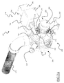
- Figure 2A is a perspective view of the pump 170 according to an advantageous embodiment of the present invention.
- Figure 2B is a partially exploded view of the pump of Figure 2A .
- the pump 170 comprises a hollow pump body 200, for example made of plastic material, having an input portion 202 and an output portion 204.
- both the input portion 202 and the output portion 204 of the pump body 200 have substantially the shape of hollow cylinders; preferably the input portion 202 has a diameter lower than the one of the output portion 204. Similar considerations apply if the input portion 202 and the output portion 204 have different shapes and/or sizes.
- the input portion 202 and the output portion 204 are connected to each other, with an end of the input portion 202 that is linked to an end of the output portion 204.
- the pump 170 has an input port 205 located preferably at a free end of the input portion 202, and connected to the discharge duct 150 (see Figure 1 ).
- the pump 170 comprises some output ports, preferably two, located preferably on a lateral surface of the output portion 204: a drain output port 210 connected to the drain duct 175, and a recirculation output port 215 connected to the recirculation conduit 180 (which recirculation conduit 180 is not illustrated in Figure 2A ).
- a pump driving motor 220 (not illustrated in Figure 2A ), preferably an electric motor, is operable to rotate an impeller 225.
- the pump driving motor 220 is advantageously connected to a free end of the output portion 204, so as to define, together with the output portion, a pump chamber 230 (which is therefore delimited by the pump body 200 and by the housing of the pump driving motor 220 itself), in which the impeller 225 is housed.
- the discharge duct 105, the drain duct 175 and the recirculation conduit 180 are adapted to be brought in fluid communication with the pump chamber 230 through the input port 205, the drain output port 210 and the recirculation output port 215, respectively.
- pump 170 is operable to selectively cause the washing liquid entering into the pump chamber 230 to be recirculated into the drum 110 through the recirculation output port 215, the recirculation conduit 180 and the nozzles 185 (see Figure 1 ), or discharged toward the water drain network system through the drain output port 210 and the drain duct 175 (see Figure 1 ).
- a diverter element 240 is provided, adapted to selectively close at least one between the recirculation output port 215 and the drain output port 210 while keeping the other one opened.
- the diverter element 240 is preferably in the form of a hollow member rotatably arranged in the pump chamber 230, upstream the recirculation output port 215 and the drain output port 210.
- the diverter element 240 has advantageously substantially the shape of a cylinder adapted to be rotatably fitted into the output portion 204 of the pump body 202.
- the diverter element 240 is made of a plastic rigid material.
- the diverter element 240 is preferably designed with an opening 255 located on the lateral surface thereof.
- the diverter element 240 is operable to be movable (advantageously, in the embodiment illustrated in enclosed Figures, it is rotatable) into the pump chamber 230 from a first position, in which the opening 255 faces the drain output port 210, to a second position, in which the opening 255 faces the recirculation port 215, and vice versa .
- Figure 2C is a cross-sectional view of the pump 170 taken along a plane perpendicular to the symmetry axis of the pump body 200 and crossing the recirculation output port 215 and the drain output port 210, in which the diverter element 240 is in the first position, i.e ., with the opening 255 that faces the drain output port 210.
- the recirculation output port 215 is blocked by a portion of the lateral surface of the diverter element 240, while the drain output port 210 is open, since the opening 255 faces the drain output port 210. In this situation, the washing liquid is diverted to the drain duct 175.
- the drain output port 210 is blocked by a portion of the lateral surface of the diverter element 240, while the recirculation output port 215 is open, since the opening 255 faces the recirculation output port 215. In this situation, the washing liquid is diverted to the recirculation conduit 180.
- the actuator system 270 comprises a linearly movable element 272, a linear actuator 274 and a transmission element 276.
- the linear actuator 274 is operable to move the linearly movable element 272 by linear motion.
- the linear motion of the linearly movable element 272 is converted into a rotational motion of the rotatable transmission element 276.
- the linearly movable element 272 is a linear gear bar provided with teeth 278 that mesh with corresponding teeth 279 provided on the rotatable transmission element 276.
- the actuator system 270 is controlled by the electronic control system 400 (e.g ., a programmable electronic board) of the washing machine 100, only schematically illustrated in Figure 1 , in such a way to take the diverter element 240 selectively in the first and second position, according to the phase of the specific washing program selected by the user (for example by a suitable user interface, not illustrated, provided in the washing machine) which is being performed.
- the electronic control system 400 e.g ., a programmable electronic board of the washing machine 100, only schematically illustrated in Figure 1 , in such a way to take the diverter element 240 selectively in the first and second position, according to the phase of the specific washing program selected by the user (for example by a suitable user interface, not illustrated, provided in the washing machine) which is being performed.
- the linear actuator 274 is located outside the pump chamber 230, for example housed in a proper support 280 fixed to the pump body 200.
- the rotatable transmission element 276 is rotatably fitted around the external surface of the input portion 202 of the pump body 200, in such a way to allow the rotatable transmission element 276 to rotate - around the symmetry axis of the pump body 202- with respect to the input portion 202 of the pump body 200.
- the rotatable transmission element 276 has advantageously substantially the shape of a "C", with the teeth 279 located on a shelf element 282 which protrudes from a surface of the rotatable transmission element 276 facing the input port 205 and which is adapted to slide substantially in contact with the external surface of the input portion 202 of the pump body 200 when the rotatable transmission element 276 is in rotation.
- rotatable transmission element 276 has a different shape, such as for example the one of a ring adapted to be fitted around the external surface of the input portion 202 of the pump body 200, and/or if the teeth 279 are located on different portions of the rotatable transmission element 276, such as for example protruding from an external border thereof.
- the rotatable transmission element 276 is magnetically coupled with the diverter element 240 so that the rotation of the rotatable transmission element 276 with respect to the input portion 202 of the pump body 202 causes a corresponding rotation of the diverter element 240 inside the pump chamber 230, without requiring any physical contact therebetween.
- one between the diverter element 240 and the rotatable transmission element 276 comprises at least one magnetic member (i.e ., able to generate a magnetic field, such as a permanent magnet), whereas the other one between the diverter element 240 and the rotatable transmission element 276 comprises at least one corresponding magneto-responsive member ( i.e ., able to be attracted or repulsed by the magnetic field generated by the magnetic member, such as a ferromagnetic material element, a ferrite element or a permanent magnet).
- a magnetic member i.e ., able to generate a magnetic field, such as a permanent magnet
- the other one between the diverter element 240 and the rotatable transmission element 276 comprises at least one corresponding magneto-responsive member (i.e ., able to be attracted or repulsed by the magnetic field generated by the magnetic member, such as a ferromagnetic material element, a ferrite element or a permanent magnet).
- the rotatable transmission element 276 is provided with a one or more (three, in the example illustrated in the figures) seats 283, for example arranged on the surface of the rotatable transmission element 276 from which the shelf element 282 protrudes, each one adapted to house a respective magnetic member 284, and the diverter element 240 is provided with one or more (three, in the example illustrated in the figures) seats 286, for example arranged on the free end of the diverter element in such a way to surround the input opening 265, each one adapted to house a respective magneto-responsive member 288.
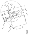
- Figure 2D is a cross sectional view of a portion of the pump taken along a plane passing through the symmetry axis of the pump body 202, in which a magnetic member 284 and a magneto-responsive member 288 are visible.
- each magnetic member 284 is adapted to magnetically couple with a corresponding magneto-responsive member 288, so that any rotational movement of the rotatable transmission element 276 causes a corresponding rotational movement of the diverter element 240.
- Figure 2E s a cross-sectional view of the pump 170 taken along a plane perpendicular to the symmetry axis of the pump body 202 and crossing the linearly movable element 272, the rotatable transmission element 276 and the input portion 202 of the pump body 200.
- the linearly movable element 272 is advantageously operable to move along a linear direction from a first, retracted, position to a second, extended, position, and vice versa .
- the linear movement of the linearly movable element 272 is advantageously converted into a corresponding rotational movement of the rotatable transmission element 276 thanks to the mechanical interaction between the teeth 278 and the teeth 279 of the rotatable transmission element 276.
- the rotational movement of the rotatable transmission element 276 is converted into a corresponding further rotational movement of the diverter element 240 thanks to the magnetic coupling between the magnetic members 284 on the rotatable transmission element 276 and the magneto-responsive member 288 on the diverter element 240.
- the diverter element 240 when the linearly movable element 272 is in the retracted position, the diverter element 240 is in the first position, with the opening 255 thereof that faces the drain output port 210. If the linearly movable element 272 is moved toward its extended position, the rotatable transmission element 276 rotates with respect to the input portion 202 of the pump body 202, so that the diverter element 240 correspondingly rotates within the pump chamber 230.
- the actuator system 270 is advantageously designed so that when the linearly movable element 272 reaches its extended position, the diverter element 240 is in the second position, with the opening 255 thereof that faces the recirculation output port 215.
- the diverter element 240 is brought from the second position to the first position by moving the linearly movable element 272 in the opposite direction, i.e ., toward its retracted position.
- the actuator system 270 is designed so that when the linearly movable element 272 reaches the retracted position, the diverter element 240 is in the second position, with the opening 255 thereof that faces the recirculation output port 215, and when reaches the extended position, the diverter element 240 is in the first position, with the opening 255 thereof that faces the drain output port 210.
- the pump according to the present invention is very efficient and cost effective. Indeed, a single pump is used to fed two different hose/conduits.
- the diverter element placed within the pump chamber can be moved from the outside of the pump body without directly contacting the diverter element, which allows obtaining a watertight coupling of the diverter element with the actuator system without requiring any additional gasket element, such as O-rings and the like, greatly simplifying the structure (and reducing the manufacturing costs) of the pump.
- the linear actuator 274 is a wax actuator, comprising a block of wax 297 enclosed in a box 298.
- the box 298 is provided with an opening exposing a portion of the block of wax 297.
- An end of the linearly movable element 272 is fixed to the exposed portion of the block of wax 297.
- Heating device preferably an electric heater, is provided for selectively heating the block of wax 297.
- the heating device is activated, the block of wax 297 is heated and it expands, driving the linearly movable element 272 outwards toward the extended position.
- the heating deice is deactivated, the block of wax 297 cools down and contracts, withdrawing the linearly movable element 272 toward the retracted position.
- the concepts of the present invention may be also applied to other linear actuators particularly suited to move a linearly movable element between two positions, such as, for example:
- the actuator system 270 may include an electric motor, for example fitted around the external surface of the input portion 202, and mechanically coupled to the rotatable transmission element 276 for rotating the latter when activated.
- the actuator system 270 does not include the rotatable transmission element 276, and the rotation of the diverter element 240 is directly caused by the contactless magnetic coupling between magnetic members 284 or magneto-responsive members 288 fitted in the diverter element 274 and corresponding at least one magneto-responsive member 288 or magnetic member 284 operable to be moved along a linear direction, for example intersecting the projection of the frontal surface 268 of the diverter element 240 along the symmetry axis of the pump body 200.
- the actuator system 270 has the linearly movable element 272 that is directly provided with at least one magneto-responsive member 288 or magnetic member 284, or which includes at least a portion made of a magneto-responsive or magnetic material.
- the linear movement of the linearly movable element 272 caused by the linear actuator 274 is directly transformed in a rotational movement of the diverter element 240 without the need of any rotatable transmission element such as the rotatable transmission element 276.
- the pump 170 may be installed in a basement element 300 which closes the casing 105 of the washing machine 100 at its bottom portion for housing and supporting at least some of the components of the washing machine 100 necessary for its operation.
- the pump 170 is advantageously provided with a support element 302 protruding from the body pump 200 (see Figures 2A-2C ) and adapted to be fixed to a corresponding portion of the basement element 300, for example by means of snap-fit engagements, pins, screws, glue or soldering.
- no discharge duct 150 is provided, and the pump 170 is directly installed on a bottom portion of the washing tub 107, for example inserted in a support element which protrudes downward from the washing tub 107 near the discharge hole 155.
Landscapes
- Engineering & Computer Science (AREA)
- Textile Engineering (AREA)
- Detail Structures Of Washing Machines And Dryers (AREA)
Claims (9)
- Eine Wäschewaschmaschine (100), die aufweist:- eine Waschwanne (107), in die eine Wasch/Spül-Flüssigkeit geladen werden kann;- ein Ablassrohr (175) zum Auslassen der aus der Waschwanne (107) gesaugten Wasch/Spül-Flüssigkeit aus der Maschine (100) heraus;- eine Rückführungsleitung (180) zum Zirkulieren der aus der Waschwanne (170) gesaugten Wasch/Spül-Flüssigkeit zurück in die Waschwanne (170);- eine Pumpe (170), die betriebsfähig ist, um selektiv zu bewirken, dass die aus der Waschwanne (107) gesaugte Wasch/Spül-Flüssigkeit über das Ablassrohr (175) ausgelassen oder über die Rückführungsleitung (180) zirkuliert wird, wobei die Pumpe (170) aufweist:a) einen Pumpenkörper (200) mit einer Pumpenkammer (230), die ein Flügelrad (225) aufnimmt, wobei die Pumpenkammer dazu ausgelegt ist, die aus der Waschwanne (107) gesaugte Wasch/Spül-Flüssigkeit aufzunehmen, undb) ein Leitelement (240), das drehbar in der Pumpenkammer (230) angeordnet ist und durch eine Drehung zwischen einer ersten Position, in der das Leitelement (240) bewirkt, dass die Wasch/Spül-Flüssigkeit in der Pumpenkammer (230) zum Ablassrohr (175) geleitet wird, und einer zweiten Position, in der das Leitelement (240) bewirkt, dass die Wasch/Spül-Flüssigkeit in der Pumpenkammer (230) zur Rückführungsleitung (180) geleitet wird, beweglich ist;
wobei:die Wäschewaschmaschine (100) ferner ein Aktuatorsystem (270) mit einem drehbaren Übertragungselement (276) aufweist, das um eine äußere Fläche des Pumpenkörpers (200) drehbar angebaut ist, wobei das drehbare Übertragungselement (276) magnetisch mit dem Leitelement (240) gekoppelt ist, so dass die Drehung des drehbaren Übertragungselements (276) in Bezug auf den Pumpenkörper (200) eine entsprechende Drehung des Leitelements (240) innerhalb der Pumpenkammer (230) bewirkt. - Die Waschmaschine (100) nach Anspruch 1, wobei:- entweder das drehbare Übertragungselement (276) oder das Leitelement (240) mindestens ein magnetisches Teil (284) aufweist und das andere zu dem drehbaren Übertragungselement (276) oder dem Leitelement (240) mindestens ein Magnetreaktionsteil (288) aufweist, wobei das drehbare Übertragungselement (276) betriebsfähig ist, um das Leitelement (240) von außerhalb des Pumpenkörpers (200) zwischen der ersten und der zweiten Position durch eine kontaktlose magnetische Kopplung zwischen dem mindestens einen magnetischen Teil (284) und dem mindestens einen Magnetreaktionsteil (288) zu bewegen.
- Die Waschmaschine (100) nach Anspruch 1 oder 2, wobei:a) die Pumpe (170) aufweist:- einen Eingangsanschluss (205), der mit der Waschwanne (107) verbunden ist;- einen Ablassausgangsanschluss (210), der mit dem Ablassrohr (175) verbunden ist, und- einen Rückführungsausgangsanschluss (215), der mit der Rückführungsleitung (180) verbunden ist,
wobei die Waschwanne (107), das Ablassrohr (175) bzw. die Rückführungsleitung (180) so ausgelegt sind, dass sie mit der Pumpenkammer (230) durch den Eingangsanschluss (205), den Ablassausgangsanschluss (210) bzw. den Rückführungsausgangsanschluss (215) in Fluidverbindung gebracht werden,
und wobeib) das Leitelement (240) in einer solchen Weise angeordnet ist, um den Rückführungsausgangsanschluss (215) zu blockieren und den Ablassausgangsanschluss (210) geöffnet zu halten, wenn es in der ersten Position ist, und den Ablassausgangsanschluss (210) zu blockieren und den Rückführungsausgangsanschluss (215) geöffnet zu halten, wenn es in der zweiten Position ist. - Die Waschmaschine (100) nach Anspruch 3, wobei das Leitelement (240) ein hohles Teil aufweist, das versehen ist mit:- einer Eingangsöffnung (265), die dem Eingangsanschluss (205) zugewandt ist,
und- einer weiteren Öffnung (255), die in einer solchen Weise angeordnet ist, dass sie dem Ablassausgangsanschluss (210) zugewandt ist, wenn das Leitelement in der ersten Position ist, und dem Rückführungsausgangsanschluss (215) zugewandt ist, wenn das Leitelement (240) in der zweiten Position ist. - Die Waschmaschine (100) nach einem der Ansprüche 2 bis 4, wobei das Aktuatorsystem (270) betriebsfähig ist, um das drehbare Übertragungselement (276) zu drehen, um eine entsprechende Drehung des Leitelements (240) zwischen der ersten und der zweiten Position zu bewirken, durch kontaktlose magnetische Kopplung zwischen dem mindestens einen magnetischen Teil (284), das in dem drehbaren Übertragungselement (276) oder dem Leitelement (240) enthalten ist, und dem mindestens einen Magnetreaktionsteil (288), das im anderen zu dem drehbaren Übertragungselement (276) oder dem Leitelement (240) enthalten ist.
- Die Waschmaschine (100) nach Anspruch 5, wobei:- das drehbare Übertragungselement (276) einen oder mehrere erste Sitze (283) aufweist, die jeweils dazu ausgelegt sind, ein jeweiliges magnetisches Teil (284) oder ein jeweiliges Magnetreaktionsteil (288) aufzunehmen, und- das Leitelement (240) einen oder mehrere zweite Sitze (286) aufweist, die jeweils dazu ausgelegt sind, ein jeweiliges magnetisches Teil (284) oder ein jeweiliges Magnetreaktionsteil (288) aufzunehmen.
- Die Waschmaschine (100) nach einem der vorangehenden Ansprüche, wobei das Aktuatorsystem (270) ferner einen Elektromotor aufweist, der mit dem drehbaren Übertragungselement (276) gekoppelt ist und betriebsfähig ist, um das drehbare Übertragungselement (276) zu drehen, wenn er aktiviert wird.
- Die Waschmaschine (100) nach einem der vorangehenden Ansprüche, wobei das Aktuatorsystem (270) ferner ein linear bewegliches Element (272) aufweist, das betriebsfähig ist, um entlang einer linearen Richtung zwischen einer zurückgezogenen Position und einer ausgefahrenen Position bewegt zu werden, und Zähne (278) hat, die mit entsprechenden Zähnen (279) verzahnen, die am drehbaren Übertragungselement (276) vorgesehen sind, zum Umwandeln der linearen Bewegung des linear beweglichen Elements (272) in eine entsprechende Drehbewegung des drehbaren Übertragungselements (276).
- Die Waschmaschine (100) nach einem der vorangehenden Ansprüche, die ein elektronischen Steuersystem (400) aufweist, das dazu ausgelegt ist, das Aktuatorsystem (270) in einer solchen Weise zu steuern, um selektiv das Leitelement (240) in der ersten oder in der zweiten Position zu positionieren gemäß der Phase des durch den Benutzer ausgewählten spezifischen Waschprogramms, das durchgeführt wird.
Priority Applications (3)
| Application Number | Priority Date | Filing Date | Title |
|---|---|---|---|
| PL13173048T PL2816149T3 (pl) | 2013-06-20 | 2013-06-20 | Pompa pralki |
| EP13173048.3A EP2816149B1 (de) | 2013-06-20 | 2013-06-20 | Waschmaschinenpumpe |
| PCT/EP2014/061293 WO2014202371A1 (en) | 2013-06-20 | 2014-05-30 | Washing machine pump |
Applications Claiming Priority (1)
| Application Number | Priority Date | Filing Date | Title |
|---|---|---|---|
| EP13173048.3A EP2816149B1 (de) | 2013-06-20 | 2013-06-20 | Waschmaschinenpumpe |
Publications (2)
| Publication Number | Publication Date |
|---|---|
| EP2816149A1 EP2816149A1 (de) | 2014-12-24 |
| EP2816149B1 true EP2816149B1 (de) | 2016-11-09 |
Family
ID=48700328
Family Applications (1)
| Application Number | Title | Priority Date | Filing Date |
|---|---|---|---|
| EP13173048.3A Not-in-force EP2816149B1 (de) | 2013-06-20 | 2013-06-20 | Waschmaschinenpumpe |
Country Status (3)
| Country | Link |
|---|---|
| EP (1) | EP2816149B1 (de) |
| PL (1) | PL2816149T3 (de) |
| WO (1) | WO2014202371A1 (de) |
Families Citing this family (2)
| Publication number | Priority date | Publication date | Assignee | Title |
|---|---|---|---|---|
| EP3012458A1 (de) * | 2014-10-22 | 2016-04-27 | Vestel Beyaz Esya Sanayi Ve Ticaret A.S. | Mehrfachauslasspumpe |
| KR102552260B1 (ko) * | 2018-04-03 | 2023-07-05 | 엘지전자 주식회사 | 세탁물 처리장치 |
Family Cites Families (5)
| Publication number | Priority date | Publication date | Assignee | Title |
|---|---|---|---|---|
| US2864312A (en) * | 1955-11-21 | 1958-12-16 | Gen Electric | Two-way pump |
| GB858694A (en) * | 1958-10-31 | 1961-01-11 | Parkinson Cowan Appliances Ltd | Improvements in washing machines |
| IT1256103B (it) * | 1992-11-12 | 1995-11-28 | Candy Spa | Gruppo di filtraggio e deviazione di flusso per lavatrice a ricircolo |
| JP2001070694A (ja) * | 1999-08-18 | 2001-03-21 | Lg Electronics Inc | 洗濯機 |
| DE10133130A1 (de) * | 2001-07-07 | 2003-01-16 | Miele & Cie | Umwälzpumpe mit/ohne Heizungseinrichtung |
-
2013
- 2013-06-20 EP EP13173048.3A patent/EP2816149B1/de not_active Not-in-force
- 2013-06-20 PL PL13173048T patent/PL2816149T3/pl unknown
-
2014
- 2014-05-30 WO PCT/EP2014/061293 patent/WO2014202371A1/en not_active Ceased
Also Published As
| Publication number | Publication date |
|---|---|
| WO2014202371A1 (en) | 2014-12-24 |
| PL2816149T3 (pl) | 2017-07-31 |
| EP2816149A1 (de) | 2014-12-24 |
Similar Documents
| Publication | Publication Date | Title |
|---|---|---|
| EP2787114B1 (de) | Waschmaschinenpumpe | |
| EP2902540B1 (de) | Waschmaschine | |
| EP2890842B1 (de) | Wäschewaschmaschine | |
| EP2816149B1 (de) | Waschmaschinenpumpe | |
| US20210317606A1 (en) | Laundry treating appliance and dispenser for treating chemistries | |
| US12180641B2 (en) | Laundry washing machine | |
| EP3615726B1 (de) | Haushaltsgerät | |
| CN112041498A (zh) | 洗衣机和用于操作洗衣机的方法 | |
| US10760199B2 (en) | Household appliance with a bulk dispenser | |
| KR20200081348A (ko) | 의류처리장치 | |
| CN111910387A (zh) | 待洗物处理器具 | |
| US11773527B2 (en) | Laundry treating appliance and dispenser | |
| CN211633163U (zh) | 多路分流阀 | |
| EP2935682B1 (de) | Verbesserte waschmaschine | |
| EP3258002B1 (de) | Haushaltsgerät | |
| US11168434B2 (en) | Valve manifold with auxiliary inlet for a washing machine appliance | |
| EP3124673B1 (de) | Waschmaschine mit einer überschwemmungsschutz-sicherheitsvorrichtung | |
| US12503808B2 (en) | Water jet system for a washing machine appliance | |
| CN224077780U (zh) | 衣物处理设备及其底座组件 | |
| EP2937459B1 (de) | Waschmaschine mit Wasserspeichertank | |
| KR20170068256A (ko) | 가전기기 및 가전기기의 제어방법 |
Legal Events
| Date | Code | Title | Description |
|---|---|---|---|
| PUAI | Public reference made under article 153(3) epc to a published international application that has entered the european phase |
Free format text: ORIGINAL CODE: 0009012 |
|
| 17P | Request for examination filed |
Effective date: 20130620 |
|
| AK | Designated contracting states |
Kind code of ref document: A1 Designated state(s): AL AT BE BG CH CY CZ DE DK EE ES FI FR GB GR HR HU IE IS IT LI LT LU LV MC MK MT NL NO PL PT RO RS SE SI SK SM TR |
|
| AX | Request for extension of the european patent |
Extension state: BA ME |
|
| R17P | Request for examination filed (corrected) |
Effective date: 20150610 |
|
| RBV | Designated contracting states (corrected) |
Designated state(s): AL AT BE BG CH CY CZ DE DK EE ES FI FR GB GR HR HU IE IS IT LI LT LU LV MC MK MT NL NO PL PT RO RS SE SI SK SM TR |
|
| 17Q | First examination report despatched |
Effective date: 20151002 |
|
| GRAP | Despatch of communication of intention to grant a patent |
Free format text: ORIGINAL CODE: EPIDOSNIGR1 |
|
| RIC1 | Information provided on ipc code assigned before grant |
Ipc: D06F 39/08 20060101AFI20160531BHEP |
|
| INTG | Intention to grant announced |
Effective date: 20160629 |
|
| GRAS | Grant fee paid |
Free format text: ORIGINAL CODE: EPIDOSNIGR3 |
|
| GRAA | (expected) grant |
Free format text: ORIGINAL CODE: 0009210 |
|
| AK | Designated contracting states |
Kind code of ref document: B1 Designated state(s): AL AT BE BG CH CY CZ DE DK EE ES FI FR GB GR HR HU IE IS IT LI LT LU LV MC MK MT NL NO PL PT RO RS SE SI SK SM TR |
|
| REG | Reference to a national code |
Ref country code: GB Ref legal event code: FG4D |
|
| REG | Reference to a national code |
Ref country code: AT Ref legal event code: REF Ref document number: 844028 Country of ref document: AT Kind code of ref document: T Effective date: 20161115 Ref country code: CH Ref legal event code: EP |
|
| REG | Reference to a national code |
Ref country code: IE Ref legal event code: FG4D |
|
| REG | Reference to a national code |
Ref country code: DE Ref legal event code: R096 Ref document number: 602013013725 Country of ref document: DE |
|
| PG25 | Lapsed in a contracting state [announced via postgrant information from national office to epo] |
Ref country code: LV Free format text: LAPSE BECAUSE OF FAILURE TO SUBMIT A TRANSLATION OF THE DESCRIPTION OR TO PAY THE FEE WITHIN THE PRESCRIBED TIME-LIMIT Effective date: 20161109 |
|
| REG | Reference to a national code |
Ref country code: LT Ref legal event code: MG4D |
|
| REG | Reference to a national code |
Ref country code: NL Ref legal event code: MP Effective date: 20161109 |
|
| REG | Reference to a national code |
Ref country code: AT Ref legal event code: MK05 Ref document number: 844028 Country of ref document: AT Kind code of ref document: T Effective date: 20161109 |
|
| PG25 | Lapsed in a contracting state [announced via postgrant information from national office to epo] |
Ref country code: GR Free format text: LAPSE BECAUSE OF FAILURE TO SUBMIT A TRANSLATION OF THE DESCRIPTION OR TO PAY THE FEE WITHIN THE PRESCRIBED TIME-LIMIT Effective date: 20170210 Ref country code: SE Free format text: LAPSE BECAUSE OF FAILURE TO SUBMIT A TRANSLATION OF THE DESCRIPTION OR TO PAY THE FEE WITHIN THE PRESCRIBED TIME-LIMIT Effective date: 20161109 Ref country code: LT Free format text: LAPSE BECAUSE OF FAILURE TO SUBMIT A TRANSLATION OF THE DESCRIPTION OR TO PAY THE FEE WITHIN THE PRESCRIBED TIME-LIMIT Effective date: 20161109 Ref country code: NO Free format text: LAPSE BECAUSE OF FAILURE TO SUBMIT A TRANSLATION OF THE DESCRIPTION OR TO PAY THE FEE WITHIN THE PRESCRIBED TIME-LIMIT Effective date: 20170209 Ref country code: NL Free format text: LAPSE BECAUSE OF FAILURE TO SUBMIT A TRANSLATION OF THE DESCRIPTION OR TO PAY THE FEE WITHIN THE PRESCRIBED TIME-LIMIT Effective date: 20161109 |
|
| PG25 | Lapsed in a contracting state [announced via postgrant information from national office to epo] |
Ref country code: IS Free format text: LAPSE BECAUSE OF FAILURE TO SUBMIT A TRANSLATION OF THE DESCRIPTION OR TO PAY THE FEE WITHIN THE PRESCRIBED TIME-LIMIT Effective date: 20170309 Ref country code: RS Free format text: LAPSE BECAUSE OF FAILURE TO SUBMIT A TRANSLATION OF THE DESCRIPTION OR TO PAY THE FEE WITHIN THE PRESCRIBED TIME-LIMIT Effective date: 20161109 Ref country code: HR Free format text: LAPSE BECAUSE OF FAILURE TO SUBMIT A TRANSLATION OF THE DESCRIPTION OR TO PAY THE FEE WITHIN THE PRESCRIBED TIME-LIMIT Effective date: 20161109 Ref country code: FI Free format text: LAPSE BECAUSE OF FAILURE TO SUBMIT A TRANSLATION OF THE DESCRIPTION OR TO PAY THE FEE WITHIN THE PRESCRIBED TIME-LIMIT Effective date: 20161109 Ref country code: PT Free format text: LAPSE BECAUSE OF FAILURE TO SUBMIT A TRANSLATION OF THE DESCRIPTION OR TO PAY THE FEE WITHIN THE PRESCRIBED TIME-LIMIT Effective date: 20170309 Ref country code: AT Free format text: LAPSE BECAUSE OF FAILURE TO SUBMIT A TRANSLATION OF THE DESCRIPTION OR TO PAY THE FEE WITHIN THE PRESCRIBED TIME-LIMIT Effective date: 20161109 Ref country code: ES Free format text: LAPSE BECAUSE OF FAILURE TO SUBMIT A TRANSLATION OF THE DESCRIPTION OR TO PAY THE FEE WITHIN THE PRESCRIBED TIME-LIMIT Effective date: 20161109 |
|
| PG25 | Lapsed in a contracting state [announced via postgrant information from national office to epo] |
Ref country code: EE Free format text: LAPSE BECAUSE OF FAILURE TO SUBMIT A TRANSLATION OF THE DESCRIPTION OR TO PAY THE FEE WITHIN THE PRESCRIBED TIME-LIMIT Effective date: 20161109 Ref country code: CZ Free format text: LAPSE BECAUSE OF FAILURE TO SUBMIT A TRANSLATION OF THE DESCRIPTION OR TO PAY THE FEE WITHIN THE PRESCRIBED TIME-LIMIT Effective date: 20161109 Ref country code: DK Free format text: LAPSE BECAUSE OF FAILURE TO SUBMIT A TRANSLATION OF THE DESCRIPTION OR TO PAY THE FEE WITHIN THE PRESCRIBED TIME-LIMIT Effective date: 20161109 Ref country code: RO Free format text: LAPSE BECAUSE OF FAILURE TO SUBMIT A TRANSLATION OF THE DESCRIPTION OR TO PAY THE FEE WITHIN THE PRESCRIBED TIME-LIMIT Effective date: 20161109 Ref country code: SK Free format text: LAPSE BECAUSE OF FAILURE TO SUBMIT A TRANSLATION OF THE DESCRIPTION OR TO PAY THE FEE WITHIN THE PRESCRIBED TIME-LIMIT Effective date: 20161109 |
|
| REG | Reference to a national code |
Ref country code: DE Ref legal event code: R097 Ref document number: 602013013725 Country of ref document: DE |
|
| PG25 | Lapsed in a contracting state [announced via postgrant information from national office to epo] |
Ref country code: BE Free format text: LAPSE BECAUSE OF FAILURE TO SUBMIT A TRANSLATION OF THE DESCRIPTION OR TO PAY THE FEE WITHIN THE PRESCRIBED TIME-LIMIT Effective date: 20161109 Ref country code: SM Free format text: LAPSE BECAUSE OF FAILURE TO SUBMIT A TRANSLATION OF THE DESCRIPTION OR TO PAY THE FEE WITHIN THE PRESCRIBED TIME-LIMIT Effective date: 20161109 Ref country code: BG Free format text: LAPSE BECAUSE OF FAILURE TO SUBMIT A TRANSLATION OF THE DESCRIPTION OR TO PAY THE FEE WITHIN THE PRESCRIBED TIME-LIMIT Effective date: 20170209 |
|
| PLBE | No opposition filed within time limit |
Free format text: ORIGINAL CODE: 0009261 |
|
| STAA | Information on the status of an ep patent application or granted ep patent |
Free format text: STATUS: NO OPPOSITION FILED WITHIN TIME LIMIT |
|
| 26N | No opposition filed |
Effective date: 20170810 |
|
| PG25 | Lapsed in a contracting state [announced via postgrant information from national office to epo] |
Ref country code: SI Free format text: LAPSE BECAUSE OF FAILURE TO SUBMIT A TRANSLATION OF THE DESCRIPTION OR TO PAY THE FEE WITHIN THE PRESCRIBED TIME-LIMIT Effective date: 20161109 |
|
| PG25 | Lapsed in a contracting state [announced via postgrant information from national office to epo] |
Ref country code: MC Free format text: LAPSE BECAUSE OF FAILURE TO SUBMIT A TRANSLATION OF THE DESCRIPTION OR TO PAY THE FEE WITHIN THE PRESCRIBED TIME-LIMIT Effective date: 20161109 |
|
| REG | Reference to a national code |
Ref country code: CH Ref legal event code: PL |
|
| GBPC | Gb: european patent ceased through non-payment of renewal fee |
Effective date: 20170620 |
|
| REG | Reference to a national code |
Ref country code: IE Ref legal event code: MM4A |
|
| REG | Reference to a national code |
Ref country code: FR Ref legal event code: ST Effective date: 20180228 |
|
| PG25 | Lapsed in a contracting state [announced via postgrant information from national office to epo] |
Ref country code: LU Free format text: LAPSE BECAUSE OF NON-PAYMENT OF DUE FEES Effective date: 20170620 Ref country code: GB Free format text: LAPSE BECAUSE OF NON-PAYMENT OF DUE FEES Effective date: 20170620 Ref country code: LI Free format text: LAPSE BECAUSE OF NON-PAYMENT OF DUE FEES Effective date: 20170630 Ref country code: IE Free format text: LAPSE BECAUSE OF NON-PAYMENT OF DUE FEES Effective date: 20170620 Ref country code: CH Free format text: LAPSE BECAUSE OF NON-PAYMENT OF DUE FEES Effective date: 20170630 |
|
| PG25 | Lapsed in a contracting state [announced via postgrant information from national office to epo] |
Ref country code: FR Free format text: LAPSE BECAUSE OF NON-PAYMENT OF DUE FEES Effective date: 20170630 |
|
| PG25 | Lapsed in a contracting state [announced via postgrant information from national office to epo] |
Ref country code: MT Free format text: LAPSE BECAUSE OF NON-PAYMENT OF DUE FEES Effective date: 20170620 |
|
| PG25 | Lapsed in a contracting state [announced via postgrant information from national office to epo] |
Ref country code: HU Free format text: LAPSE BECAUSE OF FAILURE TO SUBMIT A TRANSLATION OF THE DESCRIPTION OR TO PAY THE FEE WITHIN THE PRESCRIBED TIME-LIMIT; INVALID AB INITIO Effective date: 20130620 |
|
| PG25 | Lapsed in a contracting state [announced via postgrant information from national office to epo] |
Ref country code: CY Free format text: LAPSE BECAUSE OF FAILURE TO SUBMIT A TRANSLATION OF THE DESCRIPTION OR TO PAY THE FEE WITHIN THE PRESCRIBED TIME-LIMIT Effective date: 20161109 |
|
| PG25 | Lapsed in a contracting state [announced via postgrant information from national office to epo] |
Ref country code: MK Free format text: LAPSE BECAUSE OF FAILURE TO SUBMIT A TRANSLATION OF THE DESCRIPTION OR TO PAY THE FEE WITHIN THE PRESCRIBED TIME-LIMIT Effective date: 20161109 |
|
| PG25 | Lapsed in a contracting state [announced via postgrant information from national office to epo] |
Ref country code: TR Free format text: LAPSE BECAUSE OF FAILURE TO SUBMIT A TRANSLATION OF THE DESCRIPTION OR TO PAY THE FEE WITHIN THE PRESCRIBED TIME-LIMIT Effective date: 20161109 |
|
| PG25 | Lapsed in a contracting state [announced via postgrant information from national office to epo] |
Ref country code: AL Free format text: LAPSE BECAUSE OF FAILURE TO SUBMIT A TRANSLATION OF THE DESCRIPTION OR TO PAY THE FEE WITHIN THE PRESCRIBED TIME-LIMIT Effective date: 20161109 |
|
| PGFP | Annual fee paid to national office [announced via postgrant information from national office to epo] |
Ref country code: DE Payment date: 20230627 Year of fee payment: 11 |
|
| P01 | Opt-out of the competence of the unified patent court (upc) registered |
Effective date: 20230625 |
|
| PGFP | Annual fee paid to national office [announced via postgrant information from national office to epo] |
Ref country code: PL Payment date: 20230529 Year of fee payment: 11 |
|
| PGFP | Annual fee paid to national office [announced via postgrant information from national office to epo] |
Ref country code: IT Payment date: 20230620 Year of fee payment: 11 |
|
| REG | Reference to a national code |
Ref country code: DE Ref legal event code: R119 Ref document number: 602013013725 Country of ref document: DE |
|
| PG25 | Lapsed in a contracting state [announced via postgrant information from national office to epo] |
Ref country code: DE Free format text: LAPSE BECAUSE OF NON-PAYMENT OF DUE FEES Effective date: 20250101 |
|
| PG25 | Lapsed in a contracting state [announced via postgrant information from national office to epo] |
Ref country code: IT Free format text: LAPSE BECAUSE OF NON-PAYMENT OF DUE FEES Effective date: 20240620 |
|
| PG25 | Lapsed in a contracting state [announced via postgrant information from national office to epo] |
Ref country code: PL Free format text: LAPSE BECAUSE OF NON-PAYMENT OF DUE FEES Effective date: 20240620 |