EP2816189A2 - Korrekturvorrichtung der senkrechten Durchbiegung eines oberen Querriegels des Rahmens eines Verschlusssystems - Google Patents
Korrekturvorrichtung der senkrechten Durchbiegung eines oberen Querriegels des Rahmens eines Verschlusssystems Download PDFInfo
- Publication number
- EP2816189A2 EP2816189A2 EP14172300.7A EP14172300A EP2816189A2 EP 2816189 A2 EP2816189 A2 EP 2816189A2 EP 14172300 A EP14172300 A EP 14172300A EP 2816189 A2 EP2816189 A2 EP 2816189A2
- Authority
- EP
- European Patent Office
- Prior art keywords
- joinery
- vertical reinforcement
- vertical
- box
- reinforcement
- Prior art date
- Legal status (The legal status is an assumption and is not a legal conclusion. Google has not performed a legal analysis and makes no representation as to the accuracy of the status listed.)
- Granted
Links
Images
Classifications
-
- E—FIXED CONSTRUCTIONS
- E06—DOORS, WINDOWS, SHUTTERS, OR ROLLER BLINDS IN GENERAL; LADDERS
- E06B—FIXED OR MOVABLE CLOSURES FOR OPENINGS IN BUILDINGS, VEHICLES, FENCES OR LIKE ENCLOSURES IN GENERAL, e.g. DOORS, WINDOWS, BLINDS, GATES
- E06B9/00—Screening or protective devices for wall or similar openings, with or without operating or securing mechanisms; Closures of similar construction
- E06B9/02—Shutters, movable grilles, or other safety closing devices, e.g. against burglary
- E06B9/08—Roll-type closures
- E06B9/11—Roller shutters
- E06B9/17—Parts or details of roller shutters, e.g. suspension devices, shutter boxes, wicket doors, ventilation openings
- E06B9/17007—Shutter boxes; Details or component parts thereof
- E06B9/1703—Fixing of the box; External plastering of the box
Definitions
- the present invention relates to a device for correcting the vertical deflection of an upper rail of the joinery of a door, window or the like.
- This invention also relates to a shutter box, intended to be mounted and fixed on an upper rail of the joinery, and comprising such a vertical deflection correction device.
- This invention relates to the field of the building and, more particularly, that of the manufacture of closure systems of an opening that comprises the masonry of a building.
- This invention will find a particularly suitable application in the context of a closure installation comprising, on the one hand, a closure system in the form of a door, window or the like and, on the other hand, a concealment system under form of a roller shutter equipping such a closure system.
- Such a closure system comprises, on the one hand, a joinery comprising at least lateral uprights, a bottom rail and an upper rail and, on the other hand, at least one opening mounted on the carpentry, as the case may be, pivoting or in translation.
- This carpentry is positioned in an opening that includes the masonry of a building and is secured to this masonry by fixing the lateral uprights and cross members on the masonry.
- the occultation system comprises a box surmounting the top rail of the closure system. This configuration does not make this upper crosspiece integral with the masonry. Although the box is usually attached to the top rail, this box does not have sufficient rigidity to remedy deformation, caused by a horizontal stress exerted on the closure system (wind, attempted burglary), and detrimental to an appropriate closure and opening of this system.
- the present invention aims to overcome the drawbacks of closure installations of the state of the art.
- the invention also relates to a shutter box intended to be mounted and fixed on an upper rail of the joinery of a closure system.
- This box is characterized in that it comprises a device for correcting the vertical deflection of the upper rail of the joinery, this device having the characteristics described above.
- the invention relates to an installation for closing an opening presented by the masonry of a building, this closure system comprising, on the one hand, a closure system in the form of a door, window or the like incorporating a joinery with at least side jambs and a top rail and, secondly, a concealment system incorporating a shutter box mounted and fixed on the top rail of the joinery of the closure system.
- This installation is characterized by the fact that the rolling shutter box has the characteristics described above.
- the invention relates to a device for correcting the vertical deflection of an upper rail of the joinery of a door, window or the like.
- This device comprises a vertical reinforcement immobilized with respect to the joinery (more particularly with respect to the lateral uprights of this joinery), a base intended to cooperate with the upper rail of the joinery (directly or via a solid horizontal reinforcement of this upper crossbar) and means for adjusting the vertical position of this base relative to the vertical reinforcement.
- the present invention relates to the field of the building and, more particularly, that of the manufacture of closure systems of an opening that includes the masonry of a building.
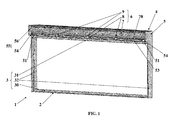
- Such a closure installation 1 comprises a closure system 2 adopting the shape of a door, a window or the like.
- Such a closure system 2 then comprises a joinery 3 constituted by a lower cross member 30, an upper cross member 31 and side posts 32 connecting the lower cross member 30 to the upper cross member 31.
- This lower cross member 30 and these lateral posts 32 are made integral with the masonry of the building.
- This closure system 2 comprises, again, at least one opening (not shown) mounted movably (pivotally or slidingly) on the joinery 3, this between an open position and a closed position of the closure system 2 .
- Said closure installation 1 comprises, again, a concealment system 4 fitted to such a closure system 2.
- a concealment system 4 adopts the form of a shutter comprising lateral slides (not shown) usually made integral with the lateral uprights 32 of the joinery 3 of the closure system 2.
- This occultation system 4 further comprises an apron (not shown) having lateral ends able to slide inside the lateral slides described above, this between a deployed position at the front of the closure system 2 and a folded position above this closure system 2.
- This occultation system 4 also comprises a box 5 inside which is folded and from which is deployed the apron mentioned above.
- This box 5 then comprises, internally, a shaft for winding said apron in the folded position inside the box 5 and for the unfolding of this deck in the deployed position in front of the closure system 2.
- This box 5 is mounted on the joinery 3, more particularly by being attached to the joinery 3, this above the top rail 31 of the joinery 3 on which 31 is then mounted the box 5. In addition, this box 5 is fixed on this joinery 3, more particularly on said upper crossbar 31.
- this box 5 comprises, then usually, an underside 50 and that it is, more particularly, this underside 50 which is mounted on the joinery 3 (more particularly being reported above of the upper rail 31 of this joinery 3) and which is fixed on this joinery 3 (more particularly on said upper cross member 31).
- This box 5 comprises, also and laterally, portions 51 of box 5, each surmounting a lateral amount 32 of the joinery 3 of the closure system 2 (or reported and / or resting on such a lateral amount 32), such amount Lateral 32 then supporting such a portion 51 of box 5.
- a portion 51 of box 5 is secured (More particularly by fixing) of the joinery 3 (more particularly of a lateral amount 32 of this joinery 3) which advantageously makes it possible to immobilize such a portion 51 of box 5 with respect to the joinery 3.
- this part 51 of box 5 is also made integral with the masonry, depending on the case, directly and / or indirectly (including being made integral with the joinery 3 as described above, this joinery 3 being , itself, made integral with the masonry).
- Such a fastening advantageously makes it possible to immobilize such a portion 51 of box 5 with respect to the masonry.
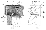
- a portion 51 of box 5 may, at least in part, be constituted by a bracket 52, laterally closing said box 5, and on which is rotatably mounted said winding shaft / unwinding of the deck .
- this box 5 may comprise a horizontal reinforcement 53 which is designed to reinforce the closure system 1 (more particularly the closure system 2) with respect to horizontal stresses (for example due to wind, an attempt to burglary ”) carried out on this closure system 2.
- Such a horizontal reinforcement 53 can equip any type of closure system 1 but is, more particularly, suitable for fitting a closure system 1 having a closure system 2 of great length.
- such a horizontal reinforcement 53 usually adopts the shape of a profile or a plate and / or is made of steel.
- This horizontal reinforcement 53 extends over at least part (even and preferably all) of the length of the box 5.
- This horizontal reinforcement 53 is secured to the upper cross member 31 of the joinery 3, more particularly by screwing .
- this horizontal reinforcement 53 is positioned over the underside 50 of the box 5, inside this box 5, and is fixed on the transom upper 31 of the joinery 3, this through said underside 50.
- this upper cross-member 31 may present a vertical jib, this under the effect of its own weight and / or of vertical stresses exerted on this upper cross-member 31.
- the closing device 1 more particularly the box 5
- the closing device 1 comprises a horizontal reinforcement 53 as described above, such a vertical stress can then result from the weight exerted by the horizontal reinforcement 53, or even the deflection of the horizontal reinforcement 53 under its own weight.
- the invention relates, then, a device 6 for correcting the vertical deflection of such an upper cross member 31 of the joinery 3 of a closure system 2 associated with the masonry of a building.
- Such a vertical reinforcement 7 comprises a horizontal bracket 70 with which cooperate the adjustment means 9 and intended to bear on at least one support 54 stationary relative to the joinery 3, more particularly with respect to at least one lateral upright 32 of this joinery 3.
- such a vertical reinforcement 7 adopts at least partly in the form of an angle, a "U" -shaped piece, a tube, a portion of a tube, a piece in a circular arc (the radius of such an arc can then correspond substantially to that of the shutter apron in the folded position in the box 5) or other.
- Such vertical reinforcement 7 may then have a horizontal portion (more particularly constituted by the horizontal bracket 70) and a vertical portion, located in the extension of the horizontal portion.
- this vertical reinforcement 7 has, advantageously, a rigidity both in the horizontal direction in the vertical direction.
- this vertical portion advantageously makes it possible to take up the stresses exerted on the horizontal part (more particularly constituted by the horizontal bracket 70) which then has a small vertical inertia.
- the horizontal portion has a flat shape and is more particularly constituted by said horizontal bracket 70.
- the vertical portion has a planar shape or (and preferably) a profile arcuate.
- Such a circular arc preferably has a radius substantially corresponding to that of the shutter apron in the folded position in the casing 5
- Such a vertical reinforcement 7 may then take the form of an angle having, on the one hand, a horizontal portion constituted by a flat wing constituting the horizontal bracket 70 and, on the other hand, a vertical portion, as the case may be , having a planar shape or (and preferably) an arcuate profile, more particularly having the characteristics mentioned above.
- such a vertical reinforcement 7 may take the form of a "U" -shaped part comprising two parallel wings (70, 71), one of which 70 constitutes the horizontal part of the vertical reinforcement 7 and / or the horizontal console 70 mentioned above.
- This "U" -shaped piece comprises, again, a bottom 72, connecting the two parallel wings (70, 71) constituting the vertical part of the vertical reinforcement 7 and / or having an arcuate profile, more particularly having the characteristics mentioned above.
- said base 8 comprises at least one horizontal flange (80, 81) with which cooperate or the adjusting means 9 and / or intended to cooperate with the upper rail 31 of the joinery 3.
- said base 8 may comprise a horizontal flange 80 with which the adjustment means or means 9 cooperate.
- this horizontal flange 80 extends parallel to the horizontal bracket 70 of the vertical reinforcement 7, more particularly above this horizontal bracket 70.
- Said base 8 may also include a horizontal flange 81 intended to cooperate with the upper cross member 31.
- such a horizontal flange 81 is intended to cooperate directly with said upper crossbar 31 of the joinery 3, this being made integral with this upper cross member 31 (directly or through the sub-frame). face 50 of the box 5), in particular by screwing.
- a closure system 1 comprising a concealment system 4 incorporating a box 5 having a horizontal reinforcement 53 as described above and secured to the upper rail 31 of the joinery 3.
- the horizontal flange 81 that comprises said base 8 is intended to cooperate with said upper cross member 31, this indirectly and through said horizontal reinforcement 53, more particularly by coming to hang under a flange of hooking that includes this horizontal reinforcement 53.
- said base 8 may be constituted by a "U" -shaped jumper or by a "U” -shaped profile comprising two parallel wings (80, 81), connected by a bottom 82, and one of which 80 cooperates with the or the adjustment means 9 and the other 81 is intended to cooperate (directly or indirectly) with said upper cross member 31.
- said wings (80, 81) and, where appropriate, the "U" profile extend horizontally and parallel to the vertical reinforcement 7, more particularly parallel to the horizontal bracket 70 of this vertical reinforcement 7.
- the correction device 6 also comprises at least one adjustment means 9.
- This or these adjustment means 9 may each be constituted by a screw, in particular a tension or compression screw, which cooperates with each other. with the base 8 as well as with the vertical reinforcement 7.
- such adjustment means 9 is interposed between the base 8 and the vertical reinforcement 7, more particularly between the horizontal flange 80 of the base 8 and the horizontal bracket 70 of the vertical reinforcement 7.
- the horizontal flange 80 of the base 8 extends parallel to and above the horizontal bracket 70 of the vertical reinforcement 7 and is traversed by the screw or screws of the adjustment means 9, such a screw bearing on the horizontal bracket 70 of this vertical reinforcement 7.
- the present invention also relates to a shutter box 5 that includes the concealment system 4 of a closure system 1.
- This box 5 has the characteristics described above. In particular and as mentioned above, this box 5 is intended to be mounted and fixed on the upper rail 31 of the joinery 3 of a closure system 2 constituted by a door, a window or the like.
- this box 5 comprises a device 6 for correcting the vertical deflection of the upper rail 31 of the joinery 3, this device 6 having, then, the characteristics described above.
- this box 5 comprises, laterally, parts 51 of box 5 which are each at least partly constituted by a lateral bracket 52.
- each of these parts 51 of box 5 is intended to be supported by a lateral amount 32 of the joinery 3 and each of these parts 51 of box 5 comprises means 55 for receiving the vertical reinforcement 7.
- these means 55 for receiving the vertical reinforcement 7 comprise a support 54 on which bears the vertical reinforcement 7 (more particularly the horizontal bracket 70 of this vertical reinforcement 7) and / or a means 56 for immobilizing the vertical reinforcement 7 by report to the caisson 5.
- the means 55 for receiving the vertical reinforcement 7 comprise a support 54 on which bears the vertical reinforcement 7.
- a support 54 on which bears the vertical reinforcement 7.
- the support of the vertical reinforcement 7 on the support 54 advantageously makes it possible to vertically immobilize this vertical reinforcement 7 with respect to the portion 51 of casing 5 which comprises this support 54 and, therefore, by compared to box 5 itself.
- the vertical reinforcement 7 does not weigh on the top rail 31 of the joinery 3 and its weight does not add to the weight of the reinforcement horizontal 53.
- Such a vertical reinforcement 7 is, in a way, self-supporting with respect to this upper crossbar 31.
- such a portion 51 of box 5 is made integral with the joinery 3 (more particularly a lateral amount 32 of this woodwork 3) which advantageously allows to immobilize, compared to the joinery 3 (more particularly with respect to a lateral amount 32 of this joinery 3), such a portion 51 of box 5 but also such a support 54 which is, then, also immobile with respect to the joinery 3 (more particularly with respect to a lateral amount 32 of this joinery 3).
- the vertical reinforcement 7 is, then, also immobile vertically with respect to the joinery 3 (more particularly with respect to a lateral amount 32 of this joinery 3)
- the means 55 for receiving the vertical reinforcement 7 comprise a means 56 for immobilizing this vertical reinforcement 7 with respect to the casing 5.
- this means for immobilizing 56 is, more particularly, designed to immobilize horizontally this vertical reinforcement 7 with respect to the box 5, but then also with respect to the joinery 3 as well as with respect to the masonry.
- such a means for immobilizing 56 is constituted by a clamp, extending internally to the box 5, equipping a bracket 52 of this box 5, and cooperating with the vertical reinforcement 7, more particularly with a lateral side of this vertical reinforcement 7.
- the box 5 may also include an apron (not shown) and a rear wall (not shown), closing the box 5, oriented towards the interior of the building receiving the box 5.
- the vertical reinforcement 7 is, then, advantageously, interposed between the apron and the rear wall.
- the box 5 (more particularly its underside 50) is intended to be secured to the upper rail 31 of the joinery 3.
- such a base 8 can cooperate directly with this upper crossbar 31, this being made integral with it, in particular by screwing (not shown).
- such a base 8 may, again, cooperate with this upper cross member 31 indirectly.
- the bases 8 cooperate with this horizontal reinforcement 53, more particularly by attachment of a wing 81 of this base 8 under a hooking flange that includes this horizontal reinforcement 53.
- Yet another characteristic of the invention consists in that the correction device 6 is advantageously positioned inside said box 5. Such a positioning is particularly advantageous with respect to a correction device interposed between the box and the box. carpentry, and which would have the effect of reducing the height of the joinery and, consequently, reducing the glazed surface.
- this box 5 has a rear wall which can be removable type, in particular at least partly constituted by a trap door.
- the invention relates to a closure installation 1 of an opening that presents the masonry of a building.
- a closure installation 1 has the characteristics mentioned above.
- such an installation 1 comprises, on the one hand, a closure system 2 in the form of a door, window or the like and incorporating a joinery 3 with at least side posts 32 and an upper cross member 31 and, on the other hand, a concealment system 4 incorporating a roller shutter box 5 mounted and fixed on the upper rail 31 of the joinery 3 of the closure system 2.
- the shutter box 5 of this closure system 1 has the characteristics described above.
- this closure device 1 comprises a box 5 which comprises, laterally, parts 51 of box 5 (more particularly side brackets 52) each supported by a lateral amount 32 of the joinery 3, and each having means 55 for receive the vertical reinforcement 7.
- such a portion 51 of box 5 comprises, then and as it emerges from the above, a support 54, supported by a lateral amount 32 of the joinery 3, and immobile (more particularly vertically) relative to this carpentry 3 (more particularly compared to a lateral amount 32 of this woodwork 3).
- This closure device 1 then also comprises a device 6 for correcting the deflection of the upper cross member 31 of the joinery 3 of its closure system 2.
- this installation 1 comprises such a device 6 comprising a vertical reinforcement 7, resting on the support 54, supported by at least one lateral upright 32 of the joinery 3, and stationary (more particularly vertically) relative to this joinery 3 (more particularly with respect to at least one lateral upright 32 of this carpentry 3).
Landscapes
- Engineering & Computer Science (AREA)
- Structural Engineering (AREA)
- Architecture (AREA)
- Civil Engineering (AREA)
- Operating, Guiding And Securing Of Roll- Type Closing Members (AREA)
Priority Applications (1)
| Application Number | Priority Date | Filing Date | Title |
|---|---|---|---|
| PL14172300T PL2816189T3 (pl) | 2013-06-20 | 2014-06-13 | Urządzenie korygujące pionową str/alkę ugięcia górnej poprzecznej belki obramowania systemu zamykającego |
Applications Claiming Priority (1)
| Application Number | Priority Date | Filing Date | Title |
|---|---|---|---|
| FR1355811A FR3007447B1 (fr) | 2013-06-20 | 2013-06-20 | Dispositif de correction de la fleche verticale d'une traverse superieure de la menuiserie d'un systeme de fermeture |
Publications (3)
| Publication Number | Publication Date |
|---|---|
| EP2816189A2 true EP2816189A2 (de) | 2014-12-24 |
| EP2816189A3 EP2816189A3 (de) | 2015-01-07 |
| EP2816189B1 EP2816189B1 (de) | 2017-08-02 |
Family
ID=49237347
Family Applications (1)
| Application Number | Title | Priority Date | Filing Date |
|---|---|---|---|
| EP14172300.7A Active EP2816189B1 (de) | 2013-06-20 | 2014-06-13 | Korrekturvorrichtung der senkrechten Durchbiegung eines oberen Querriegels des Rahmens eines Verschlusssystems |
Country Status (4)
| Country | Link |
|---|---|
| EP (1) | EP2816189B1 (de) |
| ES (1) | ES2641556T3 (de) |
| FR (1) | FR3007447B1 (de) |
| PL (1) | PL2816189T3 (de) |
Cited By (2)
| Publication number | Priority date | Publication date | Assignee | Title |
|---|---|---|---|---|
| CN110273551A (zh) * | 2019-07-17 | 2019-09-24 | 中国能源建设集团山西电力建设有限公司 | 上下叠梁连接时挠度校正装置及校正方法 |
| FR3113297A1 (fr) * | 2020-08-07 | 2022-02-11 | Societe De Production De Portes Et Fermetures | Coffre de volet roulant équipé d’une structure longitudinale de renfort intérieure |
Families Citing this family (1)
| Publication number | Priority date | Publication date | Assignee | Title |
|---|---|---|---|---|
| FR3142775B1 (fr) * | 2022-12-02 | 2024-11-29 | Soc De Production De Portes Et Fermetures | Coffre de volet roulant |
Family Cites Families (3)
| Publication number | Priority date | Publication date | Assignee | Title |
|---|---|---|---|---|
| DE9404779U1 (de) * | 1994-03-23 | 1994-06-30 | PaX GmbH, 55218 Ingelheim | Fenster- oder Türrahmen, insbesondere für darüber liegenden Rolladenkasteneinbau |
| FR2952961A1 (fr) * | 2009-11-26 | 2011-05-27 | Bubendorff | Dispositif de fermeture d'une ouverture de maconnerie d'un batiment |
| FR2974592B1 (fr) * | 2011-04-28 | 2013-06-07 | Fixolite Sa | Equipement de baie et coffre a volet roulant renforce faisant partie de cet equipement |
-
2013
- 2013-06-20 FR FR1355811A patent/FR3007447B1/fr not_active Expired - Fee Related
-
2014
- 2014-06-13 ES ES14172300.7T patent/ES2641556T3/es active Active
- 2014-06-13 EP EP14172300.7A patent/EP2816189B1/de active Active
- 2014-06-13 PL PL14172300T patent/PL2816189T3/pl unknown
Non-Patent Citations (1)
| Title |
|---|
| None |
Cited By (3)
| Publication number | Priority date | Publication date | Assignee | Title |
|---|---|---|---|---|
| CN110273551A (zh) * | 2019-07-17 | 2019-09-24 | 中国能源建设集团山西电力建设有限公司 | 上下叠梁连接时挠度校正装置及校正方法 |
| CN110273551B (zh) * | 2019-07-17 | 2024-02-09 | 中国能源建设集团山西电力建设有限公司 | 上下叠梁连接时挠度校正装置及校正方法 |
| FR3113297A1 (fr) * | 2020-08-07 | 2022-02-11 | Societe De Production De Portes Et Fermetures | Coffre de volet roulant équipé d’une structure longitudinale de renfort intérieure |
Also Published As
| Publication number | Publication date |
|---|---|
| EP2816189A3 (de) | 2015-01-07 |
| FR3007447B1 (fr) | 2017-12-01 |
| FR3007447A1 (fr) | 2014-12-26 |
| EP2816189B1 (de) | 2017-08-02 |
| PL2816189T3 (pl) | 2018-01-31 |
| ES2641556T3 (es) | 2017-11-10 |
Similar Documents
| Publication | Publication Date | Title |
|---|---|---|
| EP2816189B1 (de) | Korrekturvorrichtung der senkrechten Durchbiegung eines oberen Querriegels des Rahmens eines Verschlusssystems | |
| FR2961245A1 (fr) | Dispositif de guidage pour porte coulissante escamotable comprenant un rail demontable | |
| EP2952670B1 (de) | Herstellungs- und montageverfahren eines tors | |
| EP0952296B1 (de) | Rolladenkasten | |
| FR3118642A1 (fr) | Rail de guidage pour un store | |
| EP2873783B1 (de) | Vorrichtung zum Verschließen einer Dachöffnung | |
| FR2951475A1 (fr) | Dispositif de couverture d'un faite de mur | |
| FR2974592A1 (fr) | Equipement de baie et coffre a volet roulant renforce faisant partie de cet equipement | |
| EP2333226B1 (de) | Rolladenkasten mit aussenliegendem Verstärkungsprofil | |
| FR2901829A1 (fr) | Dispositif de montage d'au moins un vantail coulissant | |
| FR3043124B1 (fr) | Menuiserie du type porte ou fenetre equipee d'un volet roulant accessible de l'interieur | |
| FR2743596A1 (fr) | Volet roulant de fenetre, de porte, a structure en forme de u | |
| EP0728903B1 (de) | Rolladen für eine Tür, ein Fenster oder dergleichen | |
| FR3024487A1 (fr) | Structure de menuiserie comprenant un dormant et un coffre de volet roulant | |
| FR2562145A1 (fr) | Dispositif pour le maintien en place d'un rouleau de store et comprenant une butee mobile | |
| WO2024132748A1 (fr) | Panneau de facade de batiment et son procede d'installation | |
| FR2877682A1 (fr) | Dispositif de reglage pour portail a charnieres | |
| FR3155847A1 (fr) | Pergola comprenant un système d’assemblage et procédé de montage associé | |
| EP1369549A1 (de) | Selbsttragendes Türblatt für ein Kipptor | |
| FR3147833A1 (fr) | Support de tube de volet roulant, installation de protection, notamment de volet roulant, et procédé d’assemblage associés | |
| FR3142773A1 (fr) | Dispositif de manœuvre et d’arrêt d’un volet battant | |
| FR3147581A1 (fr) | Dispositif de précadre pour menuiserie de type fenêtre porte ou analogue. | |
| FR3042530A1 (fr) | Huisserie a multivitrage | |
| EP0911461A1 (de) | Einstückige Markise mit geschütztem Tuch | |
| FR3032219A1 (fr) | Un dispositif d'arret de vent monte sur des panneaux pliants |
Legal Events
| Date | Code | Title | Description |
|---|---|---|---|
| PUAL | Search report despatched |
Free format text: ORIGINAL CODE: 0009013 |
|
| PUAI | Public reference made under article 153(3) epc to a published international application that has entered the european phase |
Free format text: ORIGINAL CODE: 0009012 |
|
| 17P | Request for examination filed |
Effective date: 20140613 |
|
| AK | Designated contracting states |
Kind code of ref document: A2 Designated state(s): AL AT BE BG CH CY CZ DE DK EE ES FI FR GB GR HR HU IE IS IT LI LT LU LV MC MK MT NL NO PL PT RO RS SE SI SK SM TR |
|
| AX | Request for extension of the european patent |
Extension state: BA ME |
|
| AK | Designated contracting states |
Kind code of ref document: A3 Designated state(s): AL AT BE BG CH CY CZ DE DK EE ES FI FR GB GR HR HU IE IS IT LI LT LU LV MC MK MT NL NO PL PT RO RS SE SI SK SM TR |
|
| AX | Request for extension of the european patent |
Extension state: BA ME |
|
| RIC1 | Information provided on ipc code assigned before grant |
Ipc: E06B 9/17 20060101AFI20141128BHEP |
|
| R17P | Request for examination filed (corrected) |
Effective date: 20150626 |
|
| RBV | Designated contracting states (corrected) |
Designated state(s): AL AT BE BG CH CY CZ DE DK EE ES FI FR GB GR HR HU IE IS IT LI LT LU LV MC MK MT NL NO PL PT RO RS SE SI SK SM TR |
|
| 17Q | First examination report despatched |
Effective date: 20160725 |
|
| GRAP | Despatch of communication of intention to grant a patent |
Free format text: ORIGINAL CODE: EPIDOSNIGR1 |
|
| INTG | Intention to grant announced |
Effective date: 20170306 |
|
| GRAS | Grant fee paid |
Free format text: ORIGINAL CODE: EPIDOSNIGR3 |
|
| GRAA | (expected) grant |
Free format text: ORIGINAL CODE: 0009210 |
|
| AK | Designated contracting states |
Kind code of ref document: B1 Designated state(s): AL AT BE BG CH CY CZ DE DK EE ES FI FR GB GR HR HU IE IS IT LI LT LU LV MC MK MT NL NO PL PT RO RS SE SI SK SM TR |
|
| REG | Reference to a national code |
Ref country code: CH Ref legal event code: EP Ref country code: AT Ref legal event code: REF Ref document number: 914677 Country of ref document: AT Kind code of ref document: T Effective date: 20170815 |
|
| REG | Reference to a national code |
Ref country code: IE Ref legal event code: FG4D Free format text: LANGUAGE OF EP DOCUMENT: FRENCH |
|
| REG | Reference to a national code |
Ref country code: DE Ref legal event code: R096 Ref document number: 602014012440 Country of ref document: DE |
|
| REG | Reference to a national code |
Ref country code: ES Ref legal event code: FG2A Ref document number: 2641556 Country of ref document: ES Kind code of ref document: T3 Effective date: 20171110 |
|
| REG | Reference to a national code |
Ref country code: NL Ref legal event code: MP Effective date: 20170802 |
|
| REG | Reference to a national code |
Ref country code: AT Ref legal event code: MK05 Ref document number: 914677 Country of ref document: AT Kind code of ref document: T Effective date: 20170802 |
|
| REG | Reference to a national code |
Ref country code: LT Ref legal event code: MG4D |
|
| PG25 | Lapsed in a contracting state [announced via postgrant information from national office to epo] |
Ref country code: FI Free format text: LAPSE BECAUSE OF FAILURE TO SUBMIT A TRANSLATION OF THE DESCRIPTION OR TO PAY THE FEE WITHIN THE PRESCRIBED TIME-LIMIT Effective date: 20170802 Ref country code: AT Free format text: LAPSE BECAUSE OF FAILURE TO SUBMIT A TRANSLATION OF THE DESCRIPTION OR TO PAY THE FEE WITHIN THE PRESCRIBED TIME-LIMIT Effective date: 20170802 Ref country code: LT Free format text: LAPSE BECAUSE OF FAILURE TO SUBMIT A TRANSLATION OF THE DESCRIPTION OR TO PAY THE FEE WITHIN THE PRESCRIBED TIME-LIMIT Effective date: 20170802 Ref country code: NL Free format text: LAPSE BECAUSE OF FAILURE TO SUBMIT A TRANSLATION OF THE DESCRIPTION OR TO PAY THE FEE WITHIN THE PRESCRIBED TIME-LIMIT Effective date: 20170802 Ref country code: SE Free format text: LAPSE BECAUSE OF FAILURE TO SUBMIT A TRANSLATION OF THE DESCRIPTION OR TO PAY THE FEE WITHIN THE PRESCRIBED TIME-LIMIT Effective date: 20170802 Ref country code: NO Free format text: LAPSE BECAUSE OF FAILURE TO SUBMIT A TRANSLATION OF THE DESCRIPTION OR TO PAY THE FEE WITHIN THE PRESCRIBED TIME-LIMIT Effective date: 20171102 Ref country code: HR Free format text: LAPSE BECAUSE OF FAILURE TO SUBMIT A TRANSLATION OF THE DESCRIPTION OR TO PAY THE FEE WITHIN THE PRESCRIBED TIME-LIMIT Effective date: 20170802 |
|
| PG25 | Lapsed in a contracting state [announced via postgrant information from national office to epo] |
Ref country code: LV Free format text: LAPSE BECAUSE OF FAILURE TO SUBMIT A TRANSLATION OF THE DESCRIPTION OR TO PAY THE FEE WITHIN THE PRESCRIBED TIME-LIMIT Effective date: 20170802 Ref country code: GR Free format text: LAPSE BECAUSE OF FAILURE TO SUBMIT A TRANSLATION OF THE DESCRIPTION OR TO PAY THE FEE WITHIN THE PRESCRIBED TIME-LIMIT Effective date: 20171103 Ref country code: RS Free format text: LAPSE BECAUSE OF FAILURE TO SUBMIT A TRANSLATION OF THE DESCRIPTION OR TO PAY THE FEE WITHIN THE PRESCRIBED TIME-LIMIT Effective date: 20170802 Ref country code: BG Free format text: LAPSE BECAUSE OF FAILURE TO SUBMIT A TRANSLATION OF THE DESCRIPTION OR TO PAY THE FEE WITHIN THE PRESCRIBED TIME-LIMIT Effective date: 20171102 Ref country code: IS Free format text: LAPSE BECAUSE OF FAILURE TO SUBMIT A TRANSLATION OF THE DESCRIPTION OR TO PAY THE FEE WITHIN THE PRESCRIBED TIME-LIMIT Effective date: 20171202 |
|
| PG25 | Lapsed in a contracting state [announced via postgrant information from national office to epo] |
Ref country code: DK Free format text: LAPSE BECAUSE OF FAILURE TO SUBMIT A TRANSLATION OF THE DESCRIPTION OR TO PAY THE FEE WITHIN THE PRESCRIBED TIME-LIMIT Effective date: 20170802 Ref country code: RO Free format text: LAPSE BECAUSE OF FAILURE TO SUBMIT A TRANSLATION OF THE DESCRIPTION OR TO PAY THE FEE WITHIN THE PRESCRIBED TIME-LIMIT Effective date: 20170802 Ref country code: CZ Free format text: LAPSE BECAUSE OF FAILURE TO SUBMIT A TRANSLATION OF THE DESCRIPTION OR TO PAY THE FEE WITHIN THE PRESCRIBED TIME-LIMIT Effective date: 20170802 |
|
| REG | Reference to a national code |
Ref country code: DE Ref legal event code: R097 Ref document number: 602014012440 Country of ref document: DE |
|
| PG25 | Lapsed in a contracting state [announced via postgrant information from national office to epo] |
Ref country code: SK Free format text: LAPSE BECAUSE OF FAILURE TO SUBMIT A TRANSLATION OF THE DESCRIPTION OR TO PAY THE FEE WITHIN THE PRESCRIBED TIME-LIMIT Effective date: 20170802 Ref country code: EE Free format text: LAPSE BECAUSE OF FAILURE TO SUBMIT A TRANSLATION OF THE DESCRIPTION OR TO PAY THE FEE WITHIN THE PRESCRIBED TIME-LIMIT Effective date: 20170802 Ref country code: SM Free format text: LAPSE BECAUSE OF FAILURE TO SUBMIT A TRANSLATION OF THE DESCRIPTION OR TO PAY THE FEE WITHIN THE PRESCRIBED TIME-LIMIT Effective date: 20170802 |
|
| PLBE | No opposition filed within time limit |
Free format text: ORIGINAL CODE: 0009261 |
|
| STAA | Information on the status of an ep patent application or granted ep patent |
Free format text: STATUS: NO OPPOSITION FILED WITHIN TIME LIMIT |
|
| REG | Reference to a national code |
Ref country code: FR Ref legal event code: PLFP Year of fee payment: 5 |
|
| 26N | No opposition filed |
Effective date: 20180503 |
|
| PG25 | Lapsed in a contracting state [announced via postgrant information from national office to epo] |
Ref country code: SI Free format text: LAPSE BECAUSE OF FAILURE TO SUBMIT A TRANSLATION OF THE DESCRIPTION OR TO PAY THE FEE WITHIN THE PRESCRIBED TIME-LIMIT Effective date: 20170802 |
|
| PG25 | Lapsed in a contracting state [announced via postgrant information from national office to epo] |
Ref country code: MT Free format text: LAPSE BECAUSE OF FAILURE TO SUBMIT A TRANSLATION OF THE DESCRIPTION OR TO PAY THE FEE WITHIN THE PRESCRIBED TIME-LIMIT Effective date: 20170802 |
|
| REG | Reference to a national code |
Ref country code: CH Ref legal event code: PL |
|
| GBPC | Gb: european patent ceased through non-payment of renewal fee |
Effective date: 20180613 |
|
| REG | Reference to a national code |
Ref country code: BE Ref legal event code: MM Effective date: 20180630 |
|
| REG | Reference to a national code |
Ref country code: IE Ref legal event code: MM4A |
|
| PG25 | Lapsed in a contracting state [announced via postgrant information from national office to epo] |
Ref country code: MC Free format text: LAPSE BECAUSE OF FAILURE TO SUBMIT A TRANSLATION OF THE DESCRIPTION OR TO PAY THE FEE WITHIN THE PRESCRIBED TIME-LIMIT Effective date: 20170802 Ref country code: LU Free format text: LAPSE BECAUSE OF NON-PAYMENT OF DUE FEES Effective date: 20180613 |
|
| PG25 | Lapsed in a contracting state [announced via postgrant information from national office to epo] |
Ref country code: LI Free format text: LAPSE BECAUSE OF NON-PAYMENT OF DUE FEES Effective date: 20180630 Ref country code: CH Free format text: LAPSE BECAUSE OF NON-PAYMENT OF DUE FEES Effective date: 20180630 Ref country code: IE Free format text: LAPSE BECAUSE OF NON-PAYMENT OF DUE FEES Effective date: 20180613 Ref country code: GB Free format text: LAPSE BECAUSE OF NON-PAYMENT OF DUE FEES Effective date: 20180613 |
|
| PG25 | Lapsed in a contracting state [announced via postgrant information from national office to epo] |
Ref country code: BE Free format text: LAPSE BECAUSE OF NON-PAYMENT OF DUE FEES Effective date: 20180630 |
|
| PG25 | Lapsed in a contracting state [announced via postgrant information from national office to epo] |
Ref country code: TR Free format text: LAPSE BECAUSE OF FAILURE TO SUBMIT A TRANSLATION OF THE DESCRIPTION OR TO PAY THE FEE WITHIN THE PRESCRIBED TIME-LIMIT Effective date: 20170802 |
|
| PG25 | Lapsed in a contracting state [announced via postgrant information from national office to epo] |
Ref country code: PT Free format text: LAPSE BECAUSE OF FAILURE TO SUBMIT A TRANSLATION OF THE DESCRIPTION OR TO PAY THE FEE WITHIN THE PRESCRIBED TIME-LIMIT Effective date: 20170802 Ref country code: HU Free format text: LAPSE BECAUSE OF FAILURE TO SUBMIT A TRANSLATION OF THE DESCRIPTION OR TO PAY THE FEE WITHIN THE PRESCRIBED TIME-LIMIT; INVALID AB INITIO Effective date: 20140613 |
|
| PG25 | Lapsed in a contracting state [announced via postgrant information from national office to epo] |
Ref country code: MK Free format text: LAPSE BECAUSE OF NON-PAYMENT OF DUE FEES Effective date: 20170802 Ref country code: CY Free format text: LAPSE BECAUSE OF FAILURE TO SUBMIT A TRANSLATION OF THE DESCRIPTION OR TO PAY THE FEE WITHIN THE PRESCRIBED TIME-LIMIT Effective date: 20170802 |
|
| PG25 | Lapsed in a contracting state [announced via postgrant information from national office to epo] |
Ref country code: AL Free format text: LAPSE BECAUSE OF FAILURE TO SUBMIT A TRANSLATION OF THE DESCRIPTION OR TO PAY THE FEE WITHIN THE PRESCRIBED TIME-LIMIT Effective date: 20170802 |
|
| PGFP | Annual fee paid to national office [announced via postgrant information from national office to epo] |
Ref country code: FR Payment date: 20250317 Year of fee payment: 12 |
|
| PGFP | Annual fee paid to national office [announced via postgrant information from national office to epo] |
Ref country code: PL Payment date: 20250526 Year of fee payment: 12 Ref country code: DE Payment date: 20250617 Year of fee payment: 12 |
|
| PGFP | Annual fee paid to national office [announced via postgrant information from national office to epo] |
Ref country code: ES Payment date: 20250710 Year of fee payment: 12 |
|
| PGFP | Annual fee paid to national office [announced via postgrant information from national office to epo] |
Ref country code: IT Payment date: 20250606 Year of fee payment: 12 |