EP2816215A1 - Energieumwandlungssystem - Google Patents
Energieumwandlungssystem Download PDFInfo
- Publication number
- EP2816215A1 EP2816215A1 EP14172530.9A EP14172530A EP2816215A1 EP 2816215 A1 EP2816215 A1 EP 2816215A1 EP 14172530 A EP14172530 A EP 14172530A EP 2816215 A1 EP2816215 A1 EP 2816215A1
- Authority
- EP
- European Patent Office
- Prior art keywords
- vehicle
- heat
- stirling engine
- energy conversion
- conversion system
- Prior art date
- Legal status (The legal status is an assumption and is not a legal conclusion. Google has not performed a legal analysis and makes no representation as to the accuracy of the status listed.)
- Withdrawn
Links
Images
Classifications
-
- F—MECHANICAL ENGINEERING; LIGHTING; HEATING; WEAPONS; BLASTING
- F02—COMBUSTION ENGINES; HOT-GAS OR COMBUSTION-PRODUCT ENGINE PLANTS
- F02G—HOT GAS OR COMBUSTION-PRODUCT POSITIVE-DISPLACEMENT ENGINE PLANTS; USE OF WASTE HEAT OF COMBUSTION ENGINES; NOT OTHERWISE PROVIDED FOR
- F02G1/00—Hot gas positive-displacement engine plants
- F02G1/04—Hot gas positive-displacement engine plants of closed-cycle type
- F02G1/043—Hot gas positive-displacement engine plants of closed-cycle type the engine being operated by expansion and contraction of a mass of working gas which is heated and cooled in one of a plurality of constantly communicating expansible chambers, e.g. Stirling cycle type engines
-
- B—PERFORMING OPERATIONS; TRANSPORTING
- B60—VEHICLES IN GENERAL
- B60W—CONJOINT CONTROL OF VEHICLE SUB-UNITS OF DIFFERENT TYPE OR DIFFERENT FUNCTION; CONTROL SYSTEMS SPECIALLY ADAPTED FOR HYBRID VEHICLES; ROAD VEHICLE DRIVE CONTROL SYSTEMS FOR PURPOSES NOT RELATED TO THE CONTROL OF A PARTICULAR SUB-UNIT
- B60W30/00—Purposes of road vehicle drive control systems not related to the control of a particular sub-unit, e.g. of systems using conjoint control of vehicle sub-units
- B60W30/18—Propelling the vehicle
- B60W30/188—Controlling power parameters of the driveline, e.g. determining the required power
- B60W30/1886—Controlling power supply to auxiliary devices
-
- B—PERFORMING OPERATIONS; TRANSPORTING
- B60—VEHICLES IN GENERAL
- B60K—ARRANGEMENT OR MOUNTING OF PROPULSION UNITS OR OF TRANSMISSIONS IN VEHICLES; ARRANGEMENT OR MOUNTING OF PLURAL DIVERSE PRIME-MOVERS IN VEHICLES; AUXILIARY DRIVES FOR VEHICLES; INSTRUMENTATION OR DASHBOARDS FOR VEHICLES; ARRANGEMENTS IN CONNECTION WITH COOLING, AIR INTAKE, GAS EXHAUST OR FUEL SUPPLY OF PROPULSION UNITS IN VEHICLES
- B60K25/00—Auxiliary drives
-
- B—PERFORMING OPERATIONS; TRANSPORTING
- B60—VEHICLES IN GENERAL
- B60K—ARRANGEMENT OR MOUNTING OF PROPULSION UNITS OR OF TRANSMISSIONS IN VEHICLES; ARRANGEMENT OR MOUNTING OF PLURAL DIVERSE PRIME-MOVERS IN VEHICLES; AUXILIARY DRIVES FOR VEHICLES; INSTRUMENTATION OR DASHBOARDS FOR VEHICLES; ARRANGEMENTS IN CONNECTION WITH COOLING, AIR INTAKE, GAS EXHAUST OR FUEL SUPPLY OF PROPULSION UNITS IN VEHICLES
- B60K3/00—Arrangement or mounting of steam or gaseous-pressure propulsion units
- B60K3/02—Arrangement or mounting of steam or gaseous-pressure propulsion units of piston type
-
- F—MECHANICAL ENGINEERING; LIGHTING; HEATING; WEAPONS; BLASTING
- F01—MACHINES OR ENGINES IN GENERAL; ENGINE PLANTS IN GENERAL; STEAM ENGINES
- F01N—GAS-FLOW SILENCERS OR EXHAUST APPARATUS FOR MACHINES OR ENGINES IN GENERAL; GAS-FLOW SILENCERS OR EXHAUST APPARATUS FOR INTERNAL-COMBUSTION ENGINES
- F01N3/00—Exhaust or silencing apparatus having means for purifying, rendering innocuous, or otherwise treating exhaust
- F01N3/02—Exhaust or silencing apparatus having means for purifying, rendering innocuous, or otherwise treating exhaust for cooling, or for removing solid constituents of, exhaust
-
- F—MECHANICAL ENGINEERING; LIGHTING; HEATING; WEAPONS; BLASTING
- F01—MACHINES OR ENGINES IN GENERAL; ENGINE PLANTS IN GENERAL; STEAM ENGINES
- F01N—GAS-FLOW SILENCERS OR EXHAUST APPARATUS FOR MACHINES OR ENGINES IN GENERAL; GAS-FLOW SILENCERS OR EXHAUST APPARATUS FOR INTERNAL-COMBUSTION ENGINES
- F01N5/00—Exhaust or silencing apparatus combined or associated with devices profiting by exhaust energy
- F01N5/02—Exhaust or silencing apparatus combined or associated with devices profiting by exhaust energy the devices using heat
-
- F—MECHANICAL ENGINEERING; LIGHTING; HEATING; WEAPONS; BLASTING
- F02—COMBUSTION ENGINES; HOT-GAS OR COMBUSTION-PRODUCT ENGINE PLANTS
- F02G—HOT GAS OR COMBUSTION-PRODUCT POSITIVE-DISPLACEMENT ENGINE PLANTS; USE OF WASTE HEAT OF COMBUSTION ENGINES; NOT OTHERWISE PROVIDED FOR
- F02G5/00—Profiting from waste heat of combustion engines, not otherwise provided for
- F02G5/02—Profiting from waste heat of exhaust gases
-
- B—PERFORMING OPERATIONS; TRANSPORTING
- B60—VEHICLES IN GENERAL
- B60W—CONJOINT CONTROL OF VEHICLE SUB-UNITS OF DIFFERENT TYPE OR DIFFERENT FUNCTION; CONTROL SYSTEMS SPECIALLY ADAPTED FOR HYBRID VEHICLES; ROAD VEHICLE DRIVE CONTROL SYSTEMS FOR PURPOSES NOT RELATED TO THE CONTROL OF A PARTICULAR SUB-UNIT
- B60W2510/00—Input parameters relating to a particular sub-units
- B60W2510/06—Combustion engines, Gas turbines
- B60W2510/068—Engine exhaust temperature
-
- F—MECHANICAL ENGINEERING; LIGHTING; HEATING; WEAPONS; BLASTING
- F02—COMBUSTION ENGINES; HOT-GAS OR COMBUSTION-PRODUCT ENGINE PLANTS
- F02G—HOT GAS OR COMBUSTION-PRODUCT POSITIVE-DISPLACEMENT ENGINE PLANTS; USE OF WASTE HEAT OF COMBUSTION ENGINES; NOT OTHERWISE PROVIDED FOR
- F02G2254/00—Heat inputs
- F02G2254/15—Heat inputs by exhaust gas
-
- Y—GENERAL TAGGING OF NEW TECHNOLOGICAL DEVELOPMENTS; GENERAL TAGGING OF CROSS-SECTIONAL TECHNOLOGIES SPANNING OVER SEVERAL SECTIONS OF THE IPC; TECHNICAL SUBJECTS COVERED BY FORMER USPC CROSS-REFERENCE ART COLLECTIONS [XRACs] AND DIGESTS
- Y02—TECHNOLOGIES OR APPLICATIONS FOR MITIGATION OR ADAPTATION AGAINST CLIMATE CHANGE
- Y02E—REDUCTION OF GREENHOUSE GAS [GHG] EMISSIONS, RELATED TO ENERGY GENERATION, TRANSMISSION OR DISTRIBUTION
- Y02E20/00—Combustion technologies with mitigation potential
- Y02E20/30—Technologies for a more efficient combustion or heat usage
Definitions
- the present invention relates to an energy conversion system according to the preamble of the independent claim, and in particular an energy conversion system for a vehicle, which system comprises a Stirling engine.
- Vehicles are now provided with a wide variety of equipment which is run on electricity, e.g. lighting, radio, TV, heating etc.
- electricity e.g. lighting, radio, TV, heating etc.
- the generator cannot charge the batteries
- these various kinds of equipment will be powered by electricity from the vehicle's batteries, which is a disadvantage in that the batteries may well thus become discharged.
- a Stirling engine is a highly energy-efficient engine with characteristics appropriate to its being used in particular for vehicles with a combustion engine, since there will be access to surplus heat in the exhaust gases from the combustion engine which the Stirling engine can utilise.
- a Stirling engine there is a closed cylinder containing a gas, helium or hydrogen, which is alternately heated and cooled to drive pistons in the cylinder.
- a Stirling engine uses heat which is for example produced in a combustion chamber which is separate from the actual engine. This heat is converted to energy in the engine via the gas in the closed cylinder.
- Stirling engines which have two closed cylinders connected together so that the gas can flow between them.
- the Stirling engine technique is based on sufficient pressure differences occurring in the tight cylinder. These pressure differences are achieved by the engine having two primary elements, viz. a warm element and a cold element. When the warm element is heated the operative gas expands, creating a pressure in the cylinder. When the engine's movable parts are set in motion, the warm gas moves to the engine's cold element and is cooled, thereby reversing the pressure. So long as sufficient temperature differences can reached, the engine will continue to run.
- the gas causes the pistons of the engine to move and produce kinetic energy. All that the Stirling engine thus needs is heat and it does not matter how the heat is produced. It may be extracted from solar radiation or come from anything which burns, e.g. oil, diesel fuel, petrol or gas.
- a Stirling engine is flexible, quiet and free from vibration. It can be made to work with small temperature differences, but its efficiency increases with higher temperature differences between the warm and cold sides.
- DE-19745167 refers to a Stirling engine connected to a generator in order to generate heat or cold in a vehicle.
- US-7181912 refers to a vehicle with a combustion engine and a Stirling engine. Surplus heat from the combustion engine's exhaust gases is used by the Stirling engine's high-temperature side.
- the Stirling engine is adapted to driving at least one generator on board the vehicle in order to charge the vehicle's batteries.
- US-2013/0019595 refers to a regulating device for a Stirling engine which uses the exhaust gases from a combustion engine to heat the Stirling engine's high-temperature side.
- EP-1979601 refers to a Stirling engine which uses the surplus heat from a combustion engine.
- the object of the present invention is to alleviate the problem of a vehicle's batteries being discharged by the use of various kinds of equipment when the vehicle has switched off the combustion engine, which will then not drive the generator and therefore not charge the batteries.
- a further object is to improve the charge of the batteries even when the combustion engine is running.
- the invention is based on the inventors' insight of utilising the heat generated in a vehicle's exhaust system when its combustion engine is in operation, and of converting this heat to mechanical energy by means of a Stirling engine.
- Providing a heat module which can also receive heat from a separate heat source makes it possible for the energy conversion system to be used even when the combustion engine is not in operation.
- the Stirling engine is used to convert the thermal energy to mechanical energy which is used to drive a generator which charges the batteries, and also to drive other ancillary units.
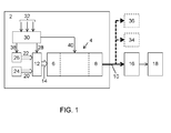
- Figure 1 is a schematic block diagram illustrating the present invention.
- the invention relates to an energy conversion system 2 for a vehicle, e.g. a truck, a bus or a car, which system comprises at least one Stirling engine 4 which has a warm side 6 and a cold side 8.
- the system 2 further comprises a motion means 10, e.g. a rotating shaft or a rod which imparts longitudinal movements, to transfer mechanical energy from the Stirling engine, and a heat module 12 situated close to the Stirling engine's warm side 6 and adapted to delivering heat 14 to said warm side in order to operate the Stirling engine.
- a motion means 10 e.g. a rotating shaft or a rod which imparts longitudinal movements, to transfer mechanical energy from the Stirling engine
- a heat module 12 situated close to the Stirling engine's warm side 6 and adapted to delivering heat 14 to said warm side in order to operate the Stirling engine.
- the motion means 10 is adapted to driving a generator 16 to charge one or more batteries 18 of the vehicle.
- the heat module 12 is adapted to receiving heat 20, 22, for delivery to the warm side of the Stirling engine, from the vehicle's exhaust system 24 and from at least one separate heat source 26.
- the heat 14, 20, 22 is schematically represented by hollow arrows.
- the heat module 12 is adapted to switching between a first operating mode in which the heat 20 from the vehicle's exhaust 24 is used and a second operating mode in which the heat 22 from a separate heat source 26 is used.
- the energy conversion system further comprises a control unit 30 adapted to receiving one or more sensor signals 32 which represent one or more operating parameters for the vehicle, and to controlling the operating mode for said heat module on the basis of said operating parameter or parameters.
- control unit 30 is adapted to generating a control signal 28 on the basis of said operating parameter or parameters and to conveying to the heat module said control signal for control of the operating mode.
- One operating parameter preferably indicates whether the vehicle's combustion engine is in operation and another operating parameter represents the temperature of the exhaust gases from the combustion engine.
- the first operating mode is activated when the temperature of the exhaust gases is above a predetermined threshold value.
- the temperature of the exhaust gases from the combustion engine of a vehicle may sometimes be as high as 750°C.
- the threshold value for activation of the first operating mode is set according to a number of criteria. Inter alia it may be set to a temperature value which ensures that the first operating mode is used when the combustion engine is working normally.
- the temperature of the exhaust gases needs to be above the threshold value for a predetermined period of time before the first operating mode is activated. This period may be of the order of a number of minutes. Its length is affected inter alia by the fact that it takes a certain time for the heat to be transferred from the exhaust gases to the Stirling engine's warm side via the heat module.
- the second operating mode is activated if the temperature of the exhaust gases is below said predetermined threshold value.
- the temperature needs to be below the threshold value for a certain time before the second operating mode is activated.
- Activation is effected by the control unit 30 generating a second control signal 38 which is conveyed to and activates the separate heat source 26.
- This separate heat source takes in one embodiment the form of a combustion chamber to burn a fuel, which may be liquid, e.g. gas, diesel fuel or petrol, or solid, e.g. pellets or wood chips.
- the motion means 10 is adapted to driving a fuel pump 34 which is adapted to pumping the fuel to the combustion chamber.
- a fuel pump 34 which is adapted to pumping the fuel to the combustion chamber.
- said motion means is adapted to driving a liquid pump 36 for the vehicle's coolant.
- the energy conversion system may be used in conjunction with a heating system for the vehicle.
- the heating system will then be constructed round or be combined with a Stirling engine which is adapted to driving a generator, and preferably a fuel pump and a coolant pump.
- the energy conversion system with the Stirling engine is a freestanding system which may for example be used as a supplementary ancillary unit to existing heaters.
- the operation of the Stirling engine 4 is substantially controlled by the control unit 30 according to a set of predetermined operating rules.
- the control unit is adapted to generating a third control signal 40 containing necessary instructions based on these operating rules for controlling the operation of the Stirling engine.
- the operating rules take inter alia into account the temperatures of the Stirling engine's warm and cold sides, and the rate of the mechanical motion imparted by the transfer means, e.g. in the form of the rotation speed of an output shaft.
- the third control signal 40 also activates a starting device for the Stirling engine to start the engine when stated requirements are fulfilled.
Landscapes
- Engineering & Computer Science (AREA)
- Mechanical Engineering (AREA)
- Chemical & Material Sciences (AREA)
- Combustion & Propulsion (AREA)
- General Engineering & Computer Science (AREA)
- Transportation (AREA)
- Automation & Control Theory (AREA)
- Engine Equipment That Uses Special Cycles (AREA)
- Air-Conditioning For Vehicles (AREA)
Applications Claiming Priority (1)
| Application Number | Priority Date | Filing Date | Title |
|---|---|---|---|
| SE1350737A SE539490C2 (sv) | 2013-06-18 | 2013-06-18 | Energiomvandlingssystem för ett fordon |
Publications (1)
| Publication Number | Publication Date |
|---|---|
| EP2816215A1 true EP2816215A1 (de) | 2014-12-24 |
Family
ID=51210972
Family Applications (1)
| Application Number | Title | Priority Date | Filing Date |
|---|---|---|---|
| EP14172530.9A Withdrawn EP2816215A1 (de) | 2013-06-18 | 2014-06-16 | Energieumwandlungssystem |
Country Status (3)
| Country | Link |
|---|---|
| EP (1) | EP2816215A1 (de) |
| CN (1) | CN104279073A (de) |
| SE (1) | SE539490C2 (de) |
Cited By (1)
| Publication number | Priority date | Publication date | Assignee | Title |
|---|---|---|---|---|
| US20190143809A1 (en) * | 2016-06-15 | 2019-05-16 | Volvo Truck Corporation | Gas tank arrangement |
Families Citing this family (1)
| Publication number | Priority date | Publication date | Assignee | Title |
|---|---|---|---|---|
| CN105370436A (zh) * | 2015-12-03 | 2016-03-02 | 北京机械设备研究所 | 一种基于斯特林发动机的汽车尾气余热回收系统 |
Citations (7)
| Publication number | Priority date | Publication date | Assignee | Title |
|---|---|---|---|---|
| DE19732307A1 (de) * | 1996-08-22 | 1998-02-26 | Volkswagen Ag | Brennkraftmaschine mit einem Stirlingmotor als Hilfsaggregat |
| DE19745167A1 (de) | 1996-10-14 | 1998-06-10 | Volkswagen Ag | Anordnung mit einer Stirlingmaschine |
| US20020017098A1 (en) * | 2000-06-14 | 2002-02-14 | Lennart Johansson | Exhaust gas alternator system |
| US7181912B2 (en) | 2003-05-09 | 2007-02-27 | Honda Motor Co., Ltd. | Power device equipped with combustion engine and stirling engine |
| EP1979601A1 (de) | 2006-02-02 | 2008-10-15 | Toyota Jidosha Kabushiki Kaisha | Vorrichtung zur rückgewinnung von abwärme |
| US20120031079A1 (en) * | 2010-08-09 | 2012-02-09 | Gm Global Technology Operations, Inc. | Hybrid powertrain system including an internal combustion engine and a stirling engine |
| US20130019595A1 (en) | 2011-07-19 | 2013-01-24 | Akio Yoshimatsu | Control apparatus and control method for stirling engine |
Family Cites Families (4)
| Publication number | Priority date | Publication date | Assignee | Title |
|---|---|---|---|---|
| US6536207B1 (en) * | 2000-03-02 | 2003-03-25 | New Power Concepts Llc | Auxiliary power unit |
| JP2003020993A (ja) * | 2002-05-28 | 2003-01-24 | Katsuhiro Ito | 排熱利用組込式熱交換器を用いたスターリングエンジン発電システム |
| GB2442006B (en) * | 2006-09-21 | 2008-08-13 | Ray Mason | Engine assemblies |
| CN102434310A (zh) * | 2011-11-29 | 2012-05-02 | 南京航空航天大学 | 内燃机-斯特林机联合循环的混合动力系统 |
-
2013
- 2013-06-18 SE SE1350737A patent/SE539490C2/sv not_active IP Right Cessation
-
2014
- 2014-06-16 EP EP14172530.9A patent/EP2816215A1/de not_active Withdrawn
- 2014-06-18 CN CN201410399765.7A patent/CN104279073A/zh active Pending
Patent Citations (7)
| Publication number | Priority date | Publication date | Assignee | Title |
|---|---|---|---|---|
| DE19732307A1 (de) * | 1996-08-22 | 1998-02-26 | Volkswagen Ag | Brennkraftmaschine mit einem Stirlingmotor als Hilfsaggregat |
| DE19745167A1 (de) | 1996-10-14 | 1998-06-10 | Volkswagen Ag | Anordnung mit einer Stirlingmaschine |
| US20020017098A1 (en) * | 2000-06-14 | 2002-02-14 | Lennart Johansson | Exhaust gas alternator system |
| US7181912B2 (en) | 2003-05-09 | 2007-02-27 | Honda Motor Co., Ltd. | Power device equipped with combustion engine and stirling engine |
| EP1979601A1 (de) | 2006-02-02 | 2008-10-15 | Toyota Jidosha Kabushiki Kaisha | Vorrichtung zur rückgewinnung von abwärme |
| US20120031079A1 (en) * | 2010-08-09 | 2012-02-09 | Gm Global Technology Operations, Inc. | Hybrid powertrain system including an internal combustion engine and a stirling engine |
| US20130019595A1 (en) | 2011-07-19 | 2013-01-24 | Akio Yoshimatsu | Control apparatus and control method for stirling engine |
Cited By (3)
| Publication number | Priority date | Publication date | Assignee | Title |
|---|---|---|---|---|
| US20190143809A1 (en) * | 2016-06-15 | 2019-05-16 | Volvo Truck Corporation | Gas tank arrangement |
| US11850936B2 (en) * | 2016-06-15 | 2023-12-26 | Volvo Truck Corporation | Gas tank arrangement |
| US12172513B2 (en) | 2016-06-15 | 2024-12-24 | Volvo Truck Corporation | Gas tank arrangement |
Also Published As
| Publication number | Publication date |
|---|---|
| SE539490C2 (sv) | 2017-10-03 |
| CN104279073A (zh) | 2015-01-14 |
| SE1350737A1 (sv) | 2014-12-19 |
Similar Documents
| Publication | Publication Date | Title |
|---|---|---|
| JP2904931B2 (ja) | 内燃エンジンおよび蒸気エンジンを具備したエンジン集成体 | |
| US7730723B2 (en) | Exhaust heat recovery apparatus | |
| RU2622457C1 (ru) | Двигатель внутреннего сгорания на основе изотермического сжатия, способ его работы и его управления | |
| WO2004099599A1 (ja) | 燃焼機関およびスターリング機関を備える動力装置 | |
| EP2500530A1 (de) | Turbosystem zur stromerzeugung durch wärmegewinnung aus motorenabfällen und hubkolbenmotorsystem damit | |
| JP2010504462A (ja) | 車両動力供給システム | |
| KR20130139977A (ko) | 통합된 능동형 챔버를 포함하는 자가압력조정형 압축 공기 엔진 | |
| US20140150426A1 (en) | Device and method for using the waste heat of an internal combustion engine | |
| US8453444B2 (en) | Power plant using compressed or liquefied air for energy storage | |
| CN102434257A (zh) | 车、船发动机废热发电装置 | |
| US20200392883A1 (en) | Internal combustion engine having an exhaust heat recovery system as well as a method for recovering exhaust heat | |
| WO2019084527A1 (en) | SERIES TYPE HYBRID ELECTRIC KINEMATIC CHAIN FOR EXTERNAL COMBUSTION ENGINE | |
| EP2816215A1 (de) | Energieumwandlungssystem | |
| US9541027B2 (en) | System and method for recovering waste heat | |
| EP4328433A1 (de) | System zur rückgewinnung von energie aus heissen abgasen | |
| CN103644026A (zh) | 余热加力气动内燃机 | |
| WO2016038384A1 (en) | An internal combustion engine with a 4-stroke expansion cycle | |
| RU2280777C1 (ru) | Энергетическая установка | |
| CN103967587A (zh) | 分缸式二级压缩发动机 | |
| US20150059663A1 (en) | Cooling system for machine system | |
| CN203756325U (zh) | 余热加力气动内燃机 | |
| US11920546B2 (en) | Buffered internal combustion engine | |
| CN105804860A (zh) | 一种汽车废气利用与冷却系统智能热管理系统 | |
| Tiwari et al. | A Review on Waste Heat Recovery and Reused of Exhaust Gases from Diesel Engines | |
| WO2012125040A1 (en) | Method for powering a nuclear reactor's cooling pumps and other equipment by using the energy in the reactor's cooling water to power hot gas engines / stirling engines |
Legal Events
| Date | Code | Title | Description |
|---|---|---|---|
| PUAI | Public reference made under article 153(3) epc to a published international application that has entered the european phase |
Free format text: ORIGINAL CODE: 0009012 |
|
| 17P | Request for examination filed |
Effective date: 20140616 |
|
| AK | Designated contracting states |
Kind code of ref document: A1 Designated state(s): AL AT BE BG CH CY CZ DE DK EE ES FI FR GB GR HR HU IE IS IT LI LT LU LV MC MK MT NL NO PL PT RO RS SE SI SK SM TR |
|
| AX | Request for extension of the european patent |
Extension state: BA ME |
|
| R17P | Request for examination filed (corrected) |
Effective date: 20150624 |
|
| RBV | Designated contracting states (corrected) |
Designated state(s): AL AT BE BG CH CY CZ DE DK EE ES FI FR GB GR HR HU IE IS IT LI LT LU LV MC MK MT NL NO PL PT RO RS SE SI SK SM TR |
|
| 17Q | First examination report despatched |
Effective date: 20180530 |
|
| STAA | Information on the status of an ep patent application or granted ep patent |
Free format text: STATUS: THE APPLICATION IS DEEMED TO BE WITHDRAWN |
|
| 18D | Application deemed to be withdrawn |
Effective date: 20181010 |