EP2816253A2 - Réducteur épicycloïdal pour actionneur d enroulement et de déroulement - Google Patents
Réducteur épicycloïdal pour actionneur d enroulement et de déroulement Download PDFInfo
- Publication number
- EP2816253A2 EP2816253A2 EP14172089.6A EP14172089A EP2816253A2 EP 2816253 A2 EP2816253 A2 EP 2816253A2 EP 14172089 A EP14172089 A EP 14172089A EP 2816253 A2 EP2816253 A2 EP 2816253A2
- Authority
- EP
- European Patent Office
- Prior art keywords
- magnetic
- epicyclic
- gear
- epicyclic gear
- drive portion
- Prior art date
- Legal status (The legal status is an assumption and is not a legal conclusion. Google has not performed a legal analysis and makes no representation as to the accuracy of the status listed.)
- Granted
Links
Images
Classifications
-
- F—MECHANICAL ENGINEERING; LIGHTING; HEATING; WEAPONS; BLASTING
- F16—ENGINEERING ELEMENTS AND UNITS; GENERAL MEASURES FOR PRODUCING AND MAINTAINING EFFECTIVE FUNCTIONING OF MACHINES OR INSTALLATIONS; THERMAL INSULATION IN GENERAL
- F16H—GEARING
- F16H1/00—Toothed gearings for conveying rotary motion
- F16H1/28—Toothed gearings for conveying rotary motion with gears having orbital motion
- F16H1/46—Systems consisting of a plurality of gear trains each with orbital gears, i.e. systems having three or more central gears
-
- E—FIXED CONSTRUCTIONS
- E06—DOORS, WINDOWS, SHUTTERS, OR ROLLER BLINDS IN GENERAL; LADDERS
- E06B—FIXED OR MOVABLE CLOSURES FOR OPENINGS IN BUILDINGS, VEHICLES, FENCES OR LIKE ENCLOSURES IN GENERAL, e.g. DOORS, WINDOWS, BLINDS, GATES
- E06B9/00—Screening or protective devices for wall or similar openings, with or without operating or securing mechanisms; Closures of similar construction
- E06B9/56—Operating, guiding or securing devices or arrangements for roll-type closures; Spring drums; Tape drums; Counterweighting arrangements therefor
- E06B9/68—Operating devices or mechanisms, e.g. with electric drive
- E06B9/72—Operating devices or mechanisms, e.g. with electric drive comprising an electric motor positioned inside the roller
-
- F—MECHANICAL ENGINEERING; LIGHTING; HEATING; WEAPONS; BLASTING
- F16—ENGINEERING ELEMENTS AND UNITS; GENERAL MEASURES FOR PRODUCING AND MAINTAINING EFFECTIVE FUNCTIONING OF MACHINES OR INSTALLATIONS; THERMAL INSULATION IN GENERAL
- F16H—GEARING
- F16H49/00—Other gearings
- F16H49/005—Magnetic gearings with physical contact between gears
-
- E—FIXED CONSTRUCTIONS
- E06—DOORS, WINDOWS, SHUTTERS, OR ROLLER BLINDS IN GENERAL; LADDERS
- E06B—FIXED OR MOVABLE CLOSURES FOR OPENINGS IN BUILDINGS, VEHICLES, FENCES OR LIKE ENCLOSURES IN GENERAL, e.g. DOORS, WINDOWS, BLINDS, GATES
- E06B9/00—Screening or protective devices for wall or similar openings, with or without operating or securing mechanisms; Closures of similar construction
- E06B9/56—Operating, guiding or securing devices or arrangements for roll-type closures; Spring drums; Tape drums; Counterweighting arrangements therefor
- E06B9/68—Operating devices or mechanisms, e.g. with electric drive
- E06B9/72—Operating devices or mechanisms, e.g. with electric drive comprising an electric motor positioned inside the roller
- E06B2009/725—Operating devices or mechanisms, e.g. with electric drive comprising an electric motor positioned inside the roller with epicyclic or planetary gear train
Definitions
- the present invention relates to an epicyclic reduction gear and an actuator for the winding and unwinding of fabrics, screens, blinds or shutters comprising such an actuator.
- the actuator is substantially longitudinal and comprises the tubular motor, the epicyclic reduction gear and the winding and unwinding member.
- the epicyclic reduction gear comprises an input shaft coupled to the tubular motor and an output shaft coupled to the winding and unwinding member.
- the rotational speed of the input shaft is greater than the rotational speed of the output shaft.
- the epicyclic reduction gear comprises at least one epicyclic gear arranged to transmit the power of the input shaft to the output shaft by reducing the rotational speed. It is known to use an epicyclic gear train comprising two so-called planetary inner and outer coaxial shafts, satellites meshing with the two planetaries, and rotating about their common axis, a planet carrier and a connection to a frame.
- the patent EP0546995 describes an epicyclic reduction gear comprising a plurality of epicyclic gear trains in which is formed an intermediate piece having the function of uniting two complementary parts of the gearbox crown and also making it possible to obtain a tubular gearbox.
- the epicyclic reduction gear is satisfactory in that the power can be transmitted, with mechanical efficiency, from the input shaft to the gearbox output shaft by reducing the speed of rotation at each epicyclic gear train that the gearbox comprises. .
- the present invention aims to solve all or some of the disadvantages mentioned above.
- the present invention relates to an epicyclic reduction gear comprising at least two epicyclic gear trains, each epicyclic gear train comprising an input shaft, an output shaft, the output shaft of the first epicyclic gear train being coupled to the gear shaft. entry of the second epicyclic gear.
- the first epicyclic gear includes a first satellite arranged to transmit a motor torque between the input shaft and the output shaft of the first epicyclic gear.
- the first satellite comprises a magnetic drive portion arranged to cooperate with a complementary magnetic portion of the first epicyclic gear by a magnetic interaction effect between at least one magnetic pole of the magnetic drive portion and at least one magnetic pole of the complementary magnetic drive portion.
- the first satellite comprises a mechanical drive portion arranged to cooperate mechanically with a mechanical drive part complementary to the first epicyclic gear.
- the magnetic drive portion and the mechanical drive portion are integral in rotation around an axis of revolution of the first satellite, and the second epicyclic gear includes a second satellite arranged to perform a mechanical drive between the input shaft. and the output shaft of the second epicyclic gear.
- the complementary magnetic part comprises a number of pairs of magnetic poles less than or equal to two, or strictly less than three.
- the maximum difference between the number of poles of the magnetic drive portion and the number of poles of the magnetic portion complementary is greater than what could be the maximum difference between the number of teeth of two cooperating gears.
- the first epicyclic gear train comprising a purely magnetic drive portion is likely to have a ratio between the rotational speeds of its input shaft and its output shaft greater than the same ratio of a fully mechanical epicyclic gear train , the number of poles of the input shaft being two.
- the mechanical drive portion and the magnetic drive portion are axially offset along the axis of revolution of the first satellite.
- the mechanical drive portion and the magnetic drive portion are offset from each other radially relative to the axis of revolution of the first satellite.
- the mechanical drive portion and the magnetic drive portion are circular and have different outer diameters.
- the output shaft and the first satellite have a pivot connection having an axis coinciding with the axis of revolution of the first satellite, in particular the output shaft being integral with a satellite carrier of the first satellite.
- the epicyclic reduction gear further comprises a brake capable of coupling the output shaft of the first epicyclic gear train and the input shaft of the second epicyclic gear train for a motor torque of the output shaft of the first epicyclic gear train greater than a minimum motor torque, the brake being arranged to uncouple the output shaft of the first epicyclic gear and the input shaft of the second epicyclic gear train for a motor torque of the output shaft of the first epicyclic gear less than the minimum engine torque.
- the magnetic drive portion is further provided with a toothing arranged to mesh a complementary toothing disposed on the complementary magnetic portion.
- the brake described above can be combined with either a magnetic drive portion provided with a toothing or with a magnetic drive portion devoid of toothing according to the variants of embodiments.
- the arrangement of the toothing with the complementary toothing is intended to prevent a loss of synchronization between the magnetic poles of the magnetic drive portion and the magnetic poles of the complementary magnetic portion.
- each tooth of the magnetic drive portion comprises two magnetic poles of inverse polarity, each positive magnetic pole being disposed on a first side of each tooth and each negative magnetic pole being disposed of a second side of each tooth.
- the magnetic drive portion and the complementary magnetic portion are arranged to transmit a driving torque by the magnetic interaction of the magnetic poles with the corresponding magnetic poles according to a first operating regime, or by an interaction magnetic and simultaneous meshing of the toothing with the complementary toothing according to a second operating regime.
- the magnetic drive portion is arranged to transmit a nominal torque to the complementary magnetic portion.
- the first operating speed corresponds to a torque between the zero torque and the included nominal torque.
- the second operating speed corresponds to a torque strictly greater than the nominal torque: it is an over-revving operation.
- the magnetic drive portion cooperates with the complementary magnetic part without contact: this is the normal operating regime.
- the magnetic drive portion cooperates both magnetically and mechanically with the complementary magnetic portion.
- the torque transmission is magneto-mechanical. This arrangement limits the friction in the contact area between the toothing and the complementary toothing.
- the toothing and the complementary toothing comprise a plastic liner loaded with fiberglass.
- the complementary magnetic portion is attached to the input shaft of the first epicyclic gear.
- the complementary magnetic part comprises a first and a second pole, the first and the second pole being of reverse polarity.
- the complementary magnetic portion is disposed on a frame of the first epicyclic gear.
- the complementary magnetic portion is a ring attached to the frame cooperating with the magnetic drive portion of the first satellite.
- the complementary magnetic part is a planetary gear inside the frame of the first epicyclic gear.
- the magnetic drive portion comprises a plurality of magnetic poles offset in the direction of the central axis.
- the present invention also relates to a substantially longitudinal actuator for winding and unwinding webs, screens, blinds or shutters comprising the epicyclic reduction gear.
- the actuator comprises a tubular motor arranged to transmit a motor torque to the input shaft of the first epicyclic gear.
- the actuator comprises a winding and unwinding member of said webs, screens, blinds or shutters arranged to wind or unwind by a mechanical drive of the output shaft of the second epicyclic gear.
- the actuator further comprises a brake positioned after the first epicyclic gear train, the first epicyclic gear train of the epicyclic reduction gear comprising a purely magnetic drive portion.
- an actuator 1 for winding and unwinding a movable element such as canvases, screens, blinds or shutters extends substantially longitudinally. He understands a tubular housing 2 in which are positioned the elements that constitute the actuator 1.
- the actuator 1 comprises a motor 3 and an epicyclic reduction gear 4 provided with a first epicyclic gear train 5, a brake 7 and a second epicyclic gear train 9.
- the motor 3 is an asynchronous AC motor or DC with or without broom otherwise called electronically commutated motor.
- the first epicyclic gear train 5 comprises an input shaft 11 and an output shaft 13 and the second epicyclic gear train 9 comprises an input shaft 15 and an output shaft 17.
- the shafts Inlet 11, 15 are inner planetary and output shafts 13, 17 are planet carriers.
- the motor 3 is coupled to the input shaft 11 of the first epicyclic gear train 5.
- the brake 7 is inserted between the output shaft 13 of the first epicyclic gear train 5 and the input shaft 13 of the second epicyclic gear train 9 but it could also be arranged at the motor output 3 or after the second epicyclic gear train 9. It is preferably of the spring brake type, but it could also be in the form of a cam brake. It could also be an electromagnetic brake.
- the input shaft 11 and the output shaft 13 of the first epicyclic gear train 5 extend along a central axis 19 which constitutes their axis of revolution.
- the first epicyclic gear train 5 comprises a first guide bearing 23 of the output shaft 13.
- the first epicyclic gear 5 further comprises a first satellite 25 and a first ring 27 connected to a first frame 21, for example the tubular housing of the actuator.
- the first satellite 25 is able to move in rotation on itself along an axis of revolution 29 and around the central axis 19.
- the first epicyclic gear train 5 comprises a first planet carrier 31, the output shaft 13 being secured to this first planet carrier 31.
- the first satellite 25 meshing on the fixed ring 27, the rotation of the first satellite 25 thus causes the first planet carrier 31, and therefore the output shaft 13, in rotation around the central axis 19.
- the number of satellites in an epicyclic gear train is typically three or four.
- the input shaft 15 and the output shaft 17 of the second epicyclic gear 9 extend along the central axis 19.
- the central axis 19 is also the axis of revolution of the drive shaft.
- the second epicyclic gear train 9 comprises a second frame 33 and a second guide bearing 35 of the output shaft 17.
- the second epicyclic gear 9 comprises a second satellite 37 arranged to provide a mechanical drive between the input shaft 15 and the output shaft 17 of the second epicyclic gear train 9.
- the second satellite 37 is able to move in rotation on it even along an axis of revolution 39 and around the central axis 19.
- the second epicyclic gear train 9 comprises a second carrier 41, the output shaft 17 being integral with the second carrier 41.
- the second carrier 41 and the second satellite satellite 37 have a pivot connection along an axis coinciding with the axis of revolution 39 of the second satellite 37.
- the second frame 33 for example the tubular casing of the actuator 1, is also provided with a second ring 43.
- the second satellite 37 comprises a toothing and mechanically engages with external toothing of the input shaft 15 and a internal teeth of the second crown 43 fixed.
- the second satellite 37 is thus arranged to perform a rotational movement around the central axis 19 when it is driven by the input shaft 15 of the second epicyclic gear train 9, thus driving the second carrier 41, and therefore the output shaft 17, rotating about the central axis 19.
- the output shaft 17 of the second epicyclic gear 9 is coupled to a winding and unrolling member of webs, screens, blinds or shutters not shown.
- the actuator 1 further comprises a third epicyclic gear 45.
- the third epicyclic gear 45 comprises an input shaft 47 and an output shaft 49 extending along the central axis 19.
- the third epicyclic gear train 45 comprises a third frame 51, a third planet 53, a third planet carrier 55 and a third ring gear 57 arranged identically to the corresponding elements of the second epicyclic gear train 9.
- the output shaft 17 of the second epicyclic gear train 9 is coupled to the input shaft 47 of the third epicyclic gear 45.
- the output shaft 49 of the third epicyclic gear 45 is coupled to the winding and unrolling member of webs, screens, blinds or shutters, such as a tube or a winding drum.
- the second epicyclic gear 9 and the third epicyclic gear 45 are type I trains, using satellites 37, 53 with single toothing. However, it is quite possible to construct them according to a type II diagram or more, with stepped satellites, as schematically represented for the first epicyclic gear train 5. figures 1 and 2 .
- the various rings may be elements that are separate or common to at least two planetary gear trains 5, 9, 45.
- the first satellite 25 comprises on a first circumference 58 a mechanical driving portion 59 arranged to cooperate by meshing with a complementary mechanical driving portion disposed on an inner circumference 60 of the first ring 27 shown figure 1 and 2 .
- the first epicyclic gear 5 is identical according to the first and second embodiments shown in the drawings. figures 1 and 2 but has several possible arrangements as described below.
- the first satellite 25 comprises a magnetic drive portion 61 provided with a plurality of magnetic poles 63, 65, the magnetic drive portion 61 being spaced axially and radially from the mechanical drive portion 59.
- Positive magnetic poles 63 and negatives 65 are alternately arranged on a second circumference 66 of the first satellite 25.
- the input shaft 11 comprises a complementary magnetic portion 67 arranged to cooperate with the magnetic drive portion 61 by a magnetic interaction effect.
- the complementary magnetic portion 67 is also provided with a plurality of magnetic poles 63 ', 65'.
- Positive magnetic poles 63 'and negative poles 65' are alternately arranged on an outer circumference 68 of input shaft 11.
- the magnetic drive portion is smooth, that is to say that it has no teeth and cooperates exclusively with the magnetic magnetic complementary part, whose outer surface is smooth as well.
- the minimum number of pairs of magnetic poles 63 ', 65' disposed on the outer circumference 68 of the input shaft 11 is two: two positive magnetic poles 63 'and two negative magnetic poles 65', two pairs of poles magnetic 63 ', 65'. This is to be compared to a minimum number of 6 or 7 teeth classically in sun protection screen training applications. The gain in terms of reduction ratio can therefore be large, for example multiplied by two, or even multiplied by at least three compared to a mechanical gear with conventional teeth.
- the number of pairs of poles on the magnetic drive portion 61 may alternatively be chosen equal to two, three or four pairs of poles. It is also possible to reduce the diameter of the input shaft.
- the stepped satellite therefore comprises a purely magnetic driving portion 61 and a purely mechanical driving portion 59.
- the transmission of the engine torque is achieved by magnetic repulsion without contact between the magnetic drive portion 61 and the portion complementary magnetic drive 67 and mechanical engagement between the mechanical drive portion 59 and the ring 27.
- the magnetic drive portion 61 also comprises a toothing 69 arranged to cooperate with a complementary toothing 71 of the input shaft 11 and each tooth of the toothing 69 and the complementary toothing 71 comprises a positive magnetic pole 63, 63 'symbolized by the letter N and a negative magnetic pole 65, 65' symbolized by the letter S.
- Each positive magnetic pole 63, 63 ' is disposed on a first side of each tooth and each negative magnetic pole 65, 65' is disposed on a second side of each tooth.
- the magnetic poles 63, 65 of the magnetic drive portion 61 are arranged relative to the magnetic poles 63 ', 65' of the complementary magnetic portion 67 to interact by magnetic repulsion.
- the stepped satellite comprises a mechanically and magnetically driven portion 61 and a purely mechanical driving portion 59.
- the stepped satellite comprises a purely magnetic driving portion 61 and a driving portion mechanical and magnetic 59, with magnetized teeth as explained relative to the second arrangement.
- the stepped satellite comprises two mechanically and magnetically driven portions 59, 61 with magnetized teeth.
- the magnetic drive portion 61 is disposed on the first circumference 58 of the first satellite 25 in conjunction with the ring 27.
- the complementary magnetic portion 67 is then disposed on the inner circumference 60 of the first ring 27
- the mechanical drive portion 59 (or mechanical and magnetic) is then disposed on the second circumference 66 of the first satellite 5 cooperating with the complementary mechanical drive portion disposed on the outer circumference 68 of the input shaft 11.
- the first ring 27 in connection with the frame is also provided with a large number of magnetic poles, which increases the cost of parts.
- the epicyclic reduction gear 4 and the actuator 1 and different arrangements of the first epicyclic gear train 5.
- the motor 3 transmits a rotational power on the input shaft 11 of the first epicyclic gear train 5.
- the cooperation of the input shaft 5 with the first satellite 25 causes the rotation of the first satellite 25 around the central axis 19 and the rotation of the first carrier 31 secured to the output shaft 13 of the first epicyclic gear train 5.
- the rotation of the output shaft 13 opposes the operation of the brake 7, which loosens, thus allowing the drive by coupling between the output shaft 13 of the first epicyclic gear train 5 with the input shaft 15 of the second epicyclic gear train 9.
- the actuator 1 drives in rotation a tube or winding drum and acts on the deployment or folding of a flexible screen or blades.
- the rotational speed of the engine 3 is fast and the torque is low on the first shaft 11.
- the first epicyclic train 5, then the second train planetary gear 9 are arranged to reduce the rotational speed and increase the torque at the output shaft 15 of the second epicyclic train 9, in order to achieve a speed of movement of the screen that is acceptable.
- the first satellites 25 comprise a purely magnetic drive portion 61.
- This and the complementary magnetic drive portion 67 must be dimensioned so as to allow transmission of at least the torque nominal to move the screen in any position. Otherwise, the drive may slip and no longer fulfill its role.
- a controlled slip can be quite advantageous, with a mechanical brake, type cam brake or spring brake.
- the magnetic drive acts as a clutch, sliding, to avoid transmitting to the gearbox and the load this torque significantly greater torque nominal. From the point of view of the charge, this comes in a transparent way. Due to the disengagement, the output shaft 13 of the first epicyclic gear 5 is slowed, which again causes a clamping of the brake 7. The movement of the screen is stopped, and this without unnecessary stress on the various components of the reducer 4.
- the number of magnetic poles of a shaft can be reduced to at least two, it is possible to obtain high reduction ratios per stage.
- This arrangement makes it possible to reduce the number of epicyclic stages or planetary gear trains of a tubular actuator 1 (for example from four to three or from three to two).
- an epicyclic reduction gear 4 comprising a first satellite 25 provided with a magnetic drive portion 61 requires a smaller number of planetary gear trains with respect to the same gear with only mechanical drive portions.
- magneto-mechanical portions with magnetized teeth it is possible to transmit larger torques than for a purely magnetic stage, with a reduction of noise and wear compared to a purely mechanical meshing.
- the choice of the arrangement can be made according to the applications of the tubular actuator, for example depending on the type of mobile element to be driven, the size and weight of the movable element.
- the transmission of the engine torque between the magnetic drive portion 61 and the complementary magnetic drive portion 67 is achieved by magnetic repulsion without contact between the toothing 69 and the complementary toothing 71, if in a first operating speed, the motor provides a torque lower or close to the nominal torque for which the magnetic drive portion 61 and the complementary magnetic drive portion 67 have been dimensioned.
- the transmission of the engine torque between the magnetic drive portion 61 and the complementary magnetic drive portion 67 is achieved by magnetic repulsion without contact between the toothing 69 and the complementary toothing 71.
- the transmission of the engine torque between the magnetic drive portion 61 and the complementary magnetic drive portion 67 is then performed by a mechanical meshing added to the magnetic interaction, between the toothing 69 and the complementary toothing 71.
- the drive is magneto-mechanical.
- the Figures 6 and 7 illustrate the differences between a purely mechanical training and a magneto-mechanical training.
- the input shaft 15 of the second epicyclic gear 9 meshes with the second satellite 37.
- the contact 73 between the toothing of the input shaft 15 and the toothing of the second satellite 37 generates a local constraint symbolized by two arrows 75: it is a purely mechanical transmission.
- the input shaft 11 of the first epicyclic gear 5 meshes with the first satellite 25.
- the combination of a contact and magnetic repulsion forces generates a distribution of the constraint on an area represented by two sets of arrows 77: it is a magneto-mechanical transmission.
- the magneto-mechanical transmission generates less wear of the teeth than a purely mechanical transmission.
- the toothing 69 of the mechanical drive portion 61 and the complementary toothing 71 of the complementary magnetic drive portion 67 comprise a fiberglass-loaded plastic coating.
- the invention is not limited to the only embodiments of this epicyclic reduction gear, described above as an example, it encompasses all the variants.
- a magnetic drive portion 61 comprising a plurality of magnetic poles 63, 65 offset in the direction of the central axis 19.
- the complementary magnetic portion 67 then comprises a plurality of complementary magnetic poles 63 ', 65 offset along the central axis 19 and facing the magnetic poles 63, 65 of the magnetic drive portion 61.
Landscapes
- Engineering & Computer Science (AREA)
- General Engineering & Computer Science (AREA)
- Mechanical Engineering (AREA)
- Structural Engineering (AREA)
- Architecture (AREA)
- Civil Engineering (AREA)
- Retarders (AREA)
Abstract
Description
- La présente invention concerne un réducteur épicycloïdal et un actionneur pour l'enroulement et le déroulement de toiles, écrans, stores ou volets roulants comprenant un tel actionneur.
- Il est connu d'utiliser un réducteur épicycloïdal pour la transmission d'une puissance mécanique, notamment entre un moteur tubulaire et un organe d'enroulement et de déroulement desdites toiles, écrans, stores ou volets roulants. Selon l'état de la technique, l'actionneur est sensiblement longitudinal et comprend le moteur tubulaire, le réducteur épicycloïdal et l'organe d'enroulement et de déroulement.
- Le réducteur épicycloïdal comprend un arbre d'entrée accouplé au moteur tubulaire et un arbre de sortie accouplé à l'organe d'enroulement et de déroulement. La vitesse de rotation de l'arbre d'entrée est supérieure à la vitesse de rotation de l'arbre de sortie.
- Le réducteur épicycloïdal comprend au moins un train épicycloïdal agencé pour transmettre la puissance de l'arbre d'entrée à l'arbre de sortie en réduisant la vitesse de rotation. Il est connu d'utiliser un train épicycloïdal comprenant deux arbres coaxiaux dits planétaires intérieur et extérieur, des satellites engrenant avec les deux planétaires, et tournant autour de leur axe commun, un porte-satellites et une liaison à un bâti.
- Le brevet
EP0546995 , par exemple, décrit un réducteur épicycloïdal comprenant plusieurs trains épicycloïdaux dans lequel est ménagée une pièce intermédiaire ayant pour rôle d'unir deux parties complémentaires de la couronne du réducteur et permettant en outre d'obtenir un réducteur tubulaire. - Le réducteur épicycloïdal donne satisfaction en ce que la puissance peut être transmise, au rendement mécanique près, de l'arbre d'entrée à l'arbre de sortie du réducteur en réduisant la vitesse de rotation au niveau de chaque train épicycloïdal que le réducteur comporte.
- Toutefois une différence de vitesse de rotation importante entre l'entrée et la sortie d'un train épicycloïdal implique un nombre réduit de dents sur au moins un engrenage. Or ce nombre de dents est limité notamment par le diamètre ou la résistance mécanique nécessaire aux engrènements. Cette disposition a des conséquences néfastes sur la robustesse du réducteur épicycloïdal, mais également sur le niveau acoustique pour des raisons mécaniques.
- Il est aussi connu de la demande de brevet
JP2012163186 - La présente invention vise à résoudre tout ou partie des inconvénients mentionnés ci-dessus.
- A cet effet, la présente invention concerne un réducteur épicycloïdal comprenant au moins deux trains épicycloïdaux, chaque train épicycloïdal comprenant un arbre d'entrée, un arbre de sortie, l'arbre de sortie du premier train épicycloïdal étant accouplé à l'arbre d'entrée du second train épicycloïdal.
- Le premier train épicycloïdal comprend un premier satellite agencé pour transmettre un couple moteur entre l'arbre d'entrée et l'arbre de sortie du premier train épicycloïdal.
- Le premier satellite comprend une portion d'entrainement magnétique agencée pour coopérer avec une partie magnétique complémentaire du premier train épicycloïdal par un effet d'interaction magnétique entre au moins un pôle magnétique de la portion d'entraînement magnétique et au moins un pôle magnétique de la portion d'entraînement magnétique complémentaire.
- Le premier satellite comprend une portion d'entrainement mécanique agencée pour coopérer mécaniquement avec une partie d'entraînement mécanique complémentaire du premier train épicycloïdal.
- La portion d'entraînement magnétique et la portion d'entraînement mécanique sont solidaires en rotation autour d'un axe de révolution du premier satellite, et le second train épicycloïdal comprend un second satellite agencé pour réaliser un entraînement mécanique entre l'arbre d'entrée et l'arbre de sortie du second train épicycloïdal.
- Selon un aspect de l'invention, la partie magnétique complémentaire comprend un nombre de paires de pôles magnétiques inférieur ou égal à deux, ou strictement inférieur à trois.
- La différence maximale entre le nombre de pôles de la portion d'entrainement magnétique et le nombre de pôles de la partie magnétique complémentaire est supérieure à ce que pourrait être la différence maximale entre le nombre de dents de deux engrenages coopérant.
- En effet le nombre de dents ne peut pas être réduit au dessous d'une certaine limite imposée par des contraintes mécaniques.
- Ainsi il apparait que le premier train épicycloïdal comportant une portion d'entrainement purement magnétique est susceptible de présenter un rapport entre les vitesses de rotation de son arbre d'entrée et de son arbre de sortie supérieur au même rapport d'un train épicycloïdal entièrement mécanique, le nombre de pôles de l'arbre d'entrée étant de deux.
- Selon un aspect de l'invention, la portion d'entraînement mécanique et la portion d'entraînement magnétique sont décalées axialement selon l'axe de révolution du premier satellite.
- Selon un aspect de l'invention, la portion d'entraînement mécanique et la portion d'entraînement magnétique sont décalées entre elles radialement par rapport à l'axe de révolution du premier satellite.
- Selon un aspect de l'invention, la portion d'entraînement mécanique et la portion d'entraînement magnétique sont circulaires et présentent des diamètres extérieurs différents.
- Selon un aspect de l'invention, l'arbre de sortie et le premier satellite présentent une liaison pivot présentant un axe coïncidant avec l'axe de révolution du premier satellite, en particulier l'arbre de sortie étant solidaire d'un porte-satellite du premier satellite.
- Selon un aspect de l'invention, le réducteur épicycloïdal comprend en outre un frein apte à accoupler l'arbre de sortie du premier train épicycloïdal et l'arbre d'entrée du second train épicycloïdal pour un couple moteur de l'arbre de sortie du premier train épicycloïdal supérieur à un couple moteur minimum, le frein étant agencé pour désaccoupler l'arbre de sortie du premier train épicycloïdal et l'arbre d'entrée du second train épicycloïdal pour un couple moteur de l'arbre de sortie du premier train épicycloïdal inférieur au couple moteur minimum.
- Selon un aspect de l'invention, la portion d'entrainement magnétique est en outre pourvue d'une denture agencée pour engrener une denture complémentaire disposée sur la partie magnétique complémentaire.
- Il est à noter que le frein décrit ci-dessus peut être combiné soit avec une portion d'entrainement magnétique pourvue d'une denture soit avec une portion d'entrainement magnétique dépourvue de denture selon les variantes de réalisations.
- L'agencement de la denture avec la denture complémentaire est destiné à empêcher une perte de synchronisation entre les pôles magnétiques de la portion d'entrainement magnétique et les pôles magnétiques de la portion magnétique complémentaire.
- Selon un aspect de l'invention, chaque dent de la portion d'entrainement magnétique comprend deux pôles magnétiques de polarité inverse, chaque pôle magnétique positif étant disposé d'un premier côté de chaque dent et chaque pôle magnétique négatif étant disposé d'un second côté de chaque dent.
- Selon un aspect de l'invention, la portion d'entrainement magnétique et la partie magnétique complémentaire sont agencées pour transmettre un couple moteur par l'interaction magnétique des pôles magnétiques avec les pôles magnétiques correspondants selon un premier régime de fonctionnement, ou par une interaction magnétique et un engrènement simultané de la denture avec la denture complémentaire selon un deuxième régime de fonctionnement.
- La portion d'entrainement magnétique est agencée pour transmettre un couple nominal à la partie magnétique complémentaire. Le premier régime de fonctionnement correspond à un couple compris entre le couple nul et le couple nominal inclus. Le second régime de fonctionnement correspond à un couple strictement supérieur au couple nominal : Il s'agit d'un fonctionnement en surrégime.
- Lors d'un fonctionnement selon le premier régime, la portion d'entrainement magnétique coopère avec la partie magnétique complémentaire sans contact : il s'agit du régime de fonctionnement normal.
- Lors d'un fonctionnement selon le second régime, la portion d'entrainement magnétique coopère à la fois magnétiquement et mécaniquement avec la partie magnétique complémentaire.
- Toutefois, contrairement à un engrenage mécanique, la transmission du couple est magnéto-mécanique. Cette disposition limite les frottements dans la zone de contact entre la denture et la denture complémentaire.
- Selon un aspect de l'invention, la denture et la denture complémentaire comprennent un revêtement plastique chargé en fibre de verre.
- Selon un aspect de l'invention, la partie magnétique complémentaire est rapportée sur l'arbre d'entrée du premier train épicycloïdal.
- Selon un aspect de l'invention, la partie magnétique complémentaire comprend un premier et un deuxième pôle, le premier et le deuxième pôle étant de polarité inverse.
- Selon un aspect de l'invention, la partie magnétique complémentaire est disposée sur un bâti du premier train épicycloïdal.
- Selon un aspect de l'invention, la partie magnétique complémentaire est une couronne rapportée sur le bâti coopérant avec la portion d'entrainement magnétique du premier satellite.
- Selon un aspect de l'invention, la partie magnétique complémentaire est un engrenage planétaire intérieur du bâti du premier train épicycloïdal.
- Selon un autre aspect de l'invention, la portion d'entrainement magnétique comprend une pluralité de pôles magnétiques décalés dans le sens de l'axe central.
- La présente invention concerne également un actionneur sensiblement longitudinal pour l'enroulement et le déroulement de toiles, écrans, stores ou volets roulants comprenant le réducteur épicycloïdal.
- L'actionneur comprend un moteur tubulaire agencé pour transmettre un couple moteur à l'arbre d'entrée du premier train épicycloïdal.
- L'actionneur comprend un organe d'enroulement et de déroulement desdites toiles, écrans, stores ou volets roulants agencé pour procéder à l'enroulement ou au déroulement par un entrainement mécanique de l'arbre de sortie du second train épicycloïdal.
- Selon un aspect de l'invention, l'actionneur comprend en outre un frein positionné après le premier train épicycloïdal, le premier train épicycloïdal du réducteur épicycloïdal comprenant une portion d'entraînement purement magnétique.
- Selon un aspect de l'invention, le frein est à ressort ou un frein à came, ou encore un frein électromagnétique. De toute façon l'invention sera bien comprise à l'aide de la description qui suit en référence aux dessins schématiques annexés représentant, à titre d'exemple non limitatif, une forme d'exécution de ce réducteur épicycloïdal.
-
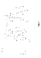
Figure 1 est un schéma d'un actionneur sensiblement longitudinal comprenant un réducteur épicycloïdal selon un premier mode de réalisation. -
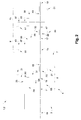
Figure 2 est un schéma d'un actionneur sensiblement longitudinal comprenant un réducteur épicycloïdal selon un deuxième mode de réalisation. -
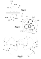
Figure 3 est une coupe longitudinale d'un premier satellite d'un premier train épicycloïdal du réducteur épicycloïdal, selon les premier et deuxième modes de réalisation. -
Figure 4 est une coupe transversale de trois premiers satellites coopérant avec une partie magnétique complémentaire d'un arbre d'entrée du premier train épicycloïdal, selon un premier agencement des premier et deuxième modes de réalisation. -
Figure 5 est une coupe transversale d'une portion magnétique d'un premier satellite coopérant avec une partie magnétique complémentaire d'un arbre d'entrée du premier train épicycloïdal, selon un deuxième agencement des premier et deuxième modes de réalisation. -
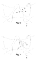
Figure 6 est une coupe transversale d'une portion d'entrainement mécanique du premier satellite coopérant avec une partie mécanique d'entrainement complémentaire, selon les premier et deuxième modes de réalisation. -
Figure 7 est une coupe transversale de la portion magnétique coopérant avec la portion magnétique complémentaire, selon les premier et deuxième modes de réalisation. - Comme illustré aux
figures 1 et2 , un actionneur 1 pour l'enroulement et le déroulement d'un élément mobile comme des toiles, écrans, stores ou volets roulants s'étend sensiblement longitudinalement. Il comprend un carter tubulaire 2 dans lequel sont positionnés les éléments qui constituent l'actionneur 1. - Selon un premier mode de réalisation illustré à la
figure 1 , l'actionneur 1 comprend un moteur 3 et un réducteur épicycloïdal 4 pourvu d'un premier train épicycloïdal 5, d'un frein 7 et d'un second train épicycloïdal 9. Le moteur 3 est un moteur AC asynchrone ou DC avec ou sans balai autrement appelé moteur à commutation électronique. - Le premier train épicycloïdal 5 comprend un arbre d'entrée 11 et un arbre de sortie 13 et le deuxième train épicycloïdal 9 comprend un arbre d'entrée 15 et un arbre de sortie 17. Selon la terminologie relative aux trains épicycloïdaux, les arbres d'entrée 11, 15 sont des planétaires intérieurs et les arbres de sortie 13, 17 sont des porte-satellites.
- Le moteur 3 est accouplé à l'arbre d'entrée 11 du premier train épicycloïdal 5. Le frein 7 s'intercale entre l'arbre de sortie 13 du premier train épicycloïdal 5 et l'arbre d'entrée 13 du second train épicycloïdal 9, mais il pourrait également être disposé en sortie de moteur 3 ou après le second train épicycloïdal 9. Il est préférentiellement de type frein à ressort, mais il pourrait également se présenter sous la forme d'un frein à came. Il pourrait également s'agir d'un frein électromagnétique.
- L'arbre d'entrée 11 et l'arbre de sortie 13 du premier train épicycloïdal 5 s'étendent selon un axe central 19 qui constitue leur axe de révolution. Le premier train épicycloïdal 5 comprend un premier palier de guidage 23 de l'arbre de sortie 13.
- Le premier train épicycloïdal 5 comprend en outre un premier satellite 25 et une première couronne 27 liée à un premier bâti 21, par exemple le carter tubulaire de l'actionneur. Le premier satellite 25 est apte à se déplacer en rotation sur lui-même suivant un l'axe de révolution 29 et autour de l'axe central 19. Le premier train épicycloïdal 5 comprend un premier porte-satellite 31, l'arbre de sortie 13 étant solidaire de ce premier porte-satellite 31. Le premier satellite 25 engrenant sur la couronne 27 fixe, la rotation du premier satellite 25 entraîne ainsi le premier porte-satellite 31, et donc l'arbre de sortie 13, en rotation autour de l'axe central 19. Le nombre de satellites dans un train épicycloïdal est classiquement de trois ou quatre.
- De manière similaire, l'arbre d'entrée 15 et l'arbre de sortie 17 du second train épicycloïdal 9 s'étendent selon l'axe central 19. L'axe central 19 est également l'axe de révolution de l'arbre d'entrée 15 et de l'arbre de sortie 17 du second train épicycloïdal 9. Le second train épicycloïdal 9 comprend un second bâti 33 et un second palier de guidage 35 de l'arbre de sortie 17.
- Le second train épicycloïdal 9 comprend un second satellite 37 agencé pour réaliser un entraînement mécanique entre l'arbre d'entrée 15 et l'arbre de sortie 17 du second train épicycloïdal 9. Le second satellite 37 est apte à se déplacer en rotation sur lui-même suivant un axe de révolution 39 et autour de l'axe central 19.
- Le second train épicycloïdal 9 comprend un second porte-satellite 41, l'arbre de sortie 17 étant solidaire du second porte-satellite 41. Le second porte-satellite 41 et le second satellite 37 présentent une liaison pivot selon un axe coïncidant avec l'axe de révolution 39 du second satellite 37.
- Le second bâti 33, par exemple le carter tubulaire de l'actionneur 1, est également pourvu d'une seconde couronne 43. Le second satellite 37 comprend une denture et coopère mécaniquement avec une denture externe de l'arbre d'entrée 15 et une denture interne de la seconde couronne 43 fixe. Le second satellite 37 est ainsi agencé pour réaliser un mouvement de rotation autour de l'axe central 19 lorsqu'il est entrainé par l'arbre d'entrée 15 du second train épicycloïdal 9, entraînant ainsi le second porte-satellite 41, et donc l'arbre de sortie 17, en rotation autour de l'axe central 19.
- Selon le premier mode de réalisation, l'arbre de sortie 17 du second train épicycloïdal 9 est couplé à un organe d'enroulement et de déroulement de toiles, écrans, stores ou volets roulants non représenté.
- Selon un second mode de réalisation illustré à la
figure 2 , l'actionneur 1 comprend en outre un troisième train épicycloïdal 45. Le troisième train épicycloïdal 45 comprend un arbre d'entrée 47 et un arbre de sortie 49 s'étendant selon l'axe central 19. - Le troisième train épicycloïdal 45 comprend un troisième bâti 51, un troisième satellite 53, un troisième porte-satellite 55 et une troisième couronne 57 agencés de manière identique aux éléments correspondants du second train épicycloïdal 9. L'arbre de sortie 17 du second train épicycloïdal 9 est accouplé à l'arbre d'entrée 47 du troisième train épicycloïdal 45. L'arbre de sortie 49 du troisième train épicycloïdal 45 est couplé à l'organe d'enroulement et de déroulement de toiles, écrans, stores ou volets roulants, tel qu'un tube ou un tambour d'enroulement.
- Ainsi que représenté, le deuxième train épicycloïdal 9 et le troisième train épicycloïdal 45 sont des trains de type I, mettant en oeuvre des satellites 37, 53 à simple denture. Toutefois, il est tout à fait possible de les construire suivant un schéma de type Il ou plus, avec des satellites 25 étagés, comme représentés schématiquement pour le premier train épicycloïdal 5 aux
figures 1 et2 . - Les différentes couronnes peuvent être des éléments séparés ou communs à au moins deux trains épicycloïdaux 5, 9, 45.
- Ci-dessus, nous avons décrit les éléments différenciant les premier et deuxième modes de réalisation. Nous allons maintenant détailler les éléments constituant le premier train épicycloïdal 5.
- Comme illustré à la
figure 3 , le premier satellite 25 comprend sur une première circonférence 58 une portion d'entrainement mécanique 59 agencée pour coopérer par engrènement à une partie d'entrainement mécanique complémentaire disposée sur une circonférence intérieure 60 de la première couronne 27 représentéefigure 1 et2 . - Le premier train épicycloïdal 5 est identique selon les premier et second mode de réalisation représentés sur les
figures 1 et2 mais présente plusieurs agencements possibles comme décrit ci-dessous. - Selon un premier agencement, illustré à la
figure 4 , le premier satellite 25 comprend une portion d'entrainement magnétique 61 pourvue d'une pluralité de pôles magnétiques 63, 65, la portion d'entrainement magnétique 61 étant distante axialement et radialement de la portion d'entrainement mécanique 59. Les pôles magnétiques positifs 63 et négatifs 65 sont disposés de manière alternée sur une seconde circonférence 66 du premier satellite 25. - L'arbre d'entrée 11 comprend une partie magnétique complémentaire 67 agencée pour coopérer avec la portion d'entrainement magnétique 61 par un effet d'interaction magnétique. Ainsi, la partie magnétique complémentaire 67 est également pourvue d'une pluralité de pôles magnétiques 63', 65'. Les pôles magnétiques positifs 63' et négatifs 65' sont disposés de manière alternée sur une circonférence extérieure 68 de l'arbre d'entrée 11.
- Selon ce premier agencement, la portion d'entraînement magnétique est lisse, c'est-à-dire qu'elle ne présente pas de denture et coopère de manière exclusivement magnétique avec la partie magnétique complémentaire, dont la surface externe est lisse également.
- Le nombre minimum de paires de pôles magnétiques 63', 65' disposés sur la circonférence extérieure 68 de l'arbre d'entrée 11 est de deux : deux pôles magnétiques positifs 63' et deux pôles magnétiques négatifs 65', soit deux paires de pôles magnétiques 63', 65'. Ceci est à comparer à un nombre minimum de 6 ou 7 dents classiquement dans les applications d'entrainement d'écrans de protection solaire. Le gain en termes de rapport de réduction peut donc être important, par exemple multiplié par deux, voire multiplié par trois au minimum par rapport à un engrènement mécanique à dentures classiques. Le nombre de paires de pôles sur la portion d'entraînement magnétique 61 peut alternativement être choisi égal à deux, trois ou quatre paires de pôles. On peut également par ailleurs réduire le diamètre de l'arbre d'entrée.
- Selon ce premier agencement, le satellite 25 étagé comprend donc une portion à entrainement purement magnétique 61 et une portion à entrainement purement mécanique 59. La transmission du couple moteur est réalisée par répulsion magnétique sans contact entre la portion d'entrainement magnétique 61 et la partie d'entrainement magnétique complémentaire 67 et par engrènement mécanique entre la portion d'entraînement mécanique 59 et la couronne 27.
- Selon un deuxième agencement, représenté à la
figure 5 , la portion d'entrainement magnétique 61 comprend également une denture 69 agencée pour coopérer avec une denture complémentaire 71 de l'arbre d'entrée 11 et chaque dent de la denture 69 et de la denture complémentaire 71 comprend un pôle magnétique positif 63, 63' symbolisé par la lettre N et un pôle magnétique négatif 65, 65' symbolisé par la lettre S. - Chaque pôle magnétique positif 63, 63' est disposé d'un premier côté de chaque dent et chaque pôle magnétique négatif 65, 65' est disposé d'un second côté de chaque dent.
- Les pôles magnétiques 63, 65 de la portion d'entrainement magnétique 61 sont disposés par rapport aux pôles magnétiques 63', 65' de la partie magnétique complémentaire 67 pour interagir par répulsion magnétique.
- Selon ce deuxième agencement, le satellite 25 étagé comprend une portion à entrainement mécanique et magnétique 61 et une portion à entrainement purement mécanique 59.
- Selon un troisième agencement, le satellite 25 étagé comprend une portion à entrainement purement magnétique 61 et une portion à entrainement mécanique et magnétique 59, avec des dentures magnétisées comme expliqué relativement au second agencement.
- Selon un quatrième agencement, le satellite 25 étagé comprend deux portions à entrainement mécanique et magnétique 59, 61 avec des dentures magnétisées.
- Il est possible également de prévoir que la portion d'entrainement magnétique 61 est disposée sur la première circonférence 58 du premier satellite 25 en liaison avec la couronne 27. La partie magnétique complémentaire 67 est alors disposée sur la circonférence intérieure 60 de la première couronne 27. La portion d'entrainement mécanique 59 (ou mécanique et magnétique) est alors disposée sur la seconde circonférence 66 du premier satellite 5 coopérant avec la partie d'entrainement mécanique complémentaire disposée sur la circonférence extérieure 68 de l'arbre d'entrée 11. Ceci implique toutefois que la première couronne 27 en lien avec le bâti soit également pourvue d'un grand nombre de pôles magnétiques, ce qui renchérit le coût des pièces.
- Nous avons décrit ci-dessus, selon deux modes de réalisation le réducteur épicycloïdal 4 et l'actionneur 1 et différents agencements du premier train épicycloïdal 5. Ci-après est présenté le fonctionnement du réducteur épicycloïdal 4 et de l'actionneur 1, notamment en lien avec un frein 7 mécanique de type frein à came ou frein à ressort.
- Le moteur 3 transmet une puissance de rotation sur l'arbre d'entrée 11 du premier train épicycloïdal 5. La coopération de l'arbre d'entrée 5 avec le premier satellite 25 engendre la rotation du premier satellite 25 autour de l'axe central 19 et la rotation du premier porte-satellite 31 solidaire de l'arbre de sortie 13 du premier train épicycloïdal 5. La rotation de l'arbre de sortie 13 s'oppose au fonctionnement du frein 7, qui se desserre, permettant ainsi l'entraînement par couplage entre l'arbre de sortie 13 du premier train épicycloïdal 5 avec l'arbre d'entrée 15 du deuxième train épicycloïdal 9.
- La puissance est ensuite transférée à l'arbre de sortie 17 du deuxième train épicycloïdal 9 ou à l'arbre de sortie 49 du troisième train épicycloïdal 45 selon le premier ou deuxième mode de réalisation. De cette façon, l'actionneur 1 entraîne en rotation un tube ou tambour d'enroulement et agit sur le déploiement ou repli d'un écran souple ou à lames.
- La vitesse de rotation du moteur 3 est rapide et le couple est faible sur le premier arbre 11. Le premier train épicycloïdal 5, puis le deuxième train épicycloïdal 9 sont agencés pour réduire la vitesse de rotation et augmenter le couple au niveau de l'arbre de sortie 15 du deuxième train épicycloïdal 9, afin d'atteindre une vitesse de déplacement de l'écran qui soit acceptable.
- Selon les premier et troisième agencements, les premiers satellites 25 comprennent une portion d'entraînement purement magnétique 61. Celle-ci, ainsi que la partie d'entrainement magnétique complémentaire 67 doivent être dimensionnées de manière à permettre une transmission d'au moins le couple nominal permettant de déplacer l'écran en toute position. Dans le cas contraire, l'entraînement peut glisser et ne plus remplir son rôle. Toutefois, un glissement maîtrisé peut être tout à fait avantageux, avec un frein mécanique, de type frein à came ou frein à ressort. Dans des cas où le moteur produit un surcouple, notamment parce que l'écran est bloqué par un obstacle, l'entraînement magnétique agit comme un débrayage, par glissement, pour éviter de transmettre vers le réducteur et la charge ce couple largement supérieur au couple nominal. Du point de vue de la charge, ceci intervient de manière transparente. Du fait du débrayage, l'arbre de sortie 13 du premier train épicycloïdal 5 est ralenti, ce qui provoque de nouveau un serrage du frein 7. Le mouvement de l'écran est donc stoppé, et ceci sans contrainte inutile sur les différents composants du réducteur 4.
- De plus, comme contrairement au nombre de dents d'un engrenage, le nombre de pôles magnétiques d'un arbre peut être réduit au minimum à deux, il est possible d'obtenir de forts rapports de réduction par étage. Cette disposition permet de réduire le nombre d'étages ou de trains épicycloïdaux du réducteur épicycloïdal d'un actionneur 1 tubulaire (par exemple de quatre à trois ou de trois à deux).
- Ainsi pour un rapport de réduction comparable, un réducteur épicycloïdal 4 comprenant un premier satellite 25 pourvu d'une portion d'entrainement magnétique 61 nécessite un nombre de trains épicycloïdaux moindre par rapport à un même réducteur avec des portions d'entraînement uniquement mécaniques.
- Par ailleurs, du fait de la suppression du contact entre les dents, on supprime des bruits et vibrations et la lubrification n'est pas nécessaire pour cet étage.
- A l'inverse, les portions magnéto-mécaniques avec des dentures magnétisées, il est possible de transmettre des couples plus importants que pour un étage purement magnétique, avec une réduction de bruit et d'usure par rapport à un engrènement purement mécanique.
- Le choix de l'agencement peut être fait en fonction des applications de l'actionneur tubulaire, par exemple en fonction du type d'élément mobile à entraîner, de la taille et du poids de l'élément mobile.
- Selon les deuxième et quatrième agencements, la transmission du couple moteur entre la portion d'entrainement magnétique 61 et la partie d'entrainement magnétique complémentaire 67 est réalisée par répulsion magnétique sans contact entre la denture 69 et la denture complémentaire 71, si dans un premier régime de fonctionnement, le moteur fournit un couple inférieur ou proche du couple nominal pour lequel la portion d'entrainement magnétique 61 et la partie d'entrainement magnétique complémentaire 67 ont été dimensionnées.
- La transmission du couple moteur entre la portion d'entrainement magnétique 61 et la partie d'entrainement magnétique complémentaire 67 est réalisée par répulsion magnétique sans contact entre la denture 69 et la denture complémentaire 71.
- Si au contraire, dans un deuxième régime de fonctionnement, le moteur 3 fournit un couple moteur supérieur au couple moteur nominal, la transmission du couple moteur entre la portion d'entrainement magnétique 61 et la partie d'entrainement magnétique complémentaire 67 est alors réalisée par un engrènement mécanique s'ajoutant à l'interaction magnétique, entre la denture 69 et la denture complémentaire 71.
- En effet au-delà du couple nominal, la répulsion des pôles magnétiques 63, 65 n'est plus suffisante pour assurer seule la transmission du couple moteur : l'entrainement est magnéto-mécanique.
- Les
figures 6 et 7 illustrent les différences entre un entrainement purement mécanique et un entrainement magnéto-mécanique. - Comme illustré à la
figure 6 , l'arbre d'entrée 15 du second train épicycloïdal 9 engrène le second satellite 37. Le contact 73 entre la denture de l'arbre d'entrée 15 et la denture du second satellite 37 engendre une contrainte locale symbolisée par deux flèches 75 : il s'agit d'une transmission purement mécanique. - Comme illustré à la
figure 7 , l'arbre d'entrée 11 du premier train épicycloïdal 5 engrène le premier satellite 25. La combinaison d'un contact et de forces de répulsion magnétique engendre une répartition de la contrainte sur une zone représentée par deux ensembles de flèches 77 : il s'agit d'une transmission magnéto-mécanique. - La transmission magnéto-mécanique engendre une usure moindre des dentures qu'une transmission purement mécanique. Ainsi, il est possible que la denture 69 de la portion d'entrainement mécanique 61 et la denture complémentaire 71 de la partie d'entrainement magnétique complémentaire 67 comprennent un revêtement plastique chargé en fibre de verre.
- Comme il va de soi, l'invention ne se limite pas aux seules modes de réalisation de ce réducteur épicycloïdal, décrits ci-dessus à titre d'exemple, elle en embrasse au contraire toutes les variantes de réalisation.
- Ainsi il est envisageable de réaliser une portion d'entrainement magnétique 61 comprenant une pluralité de pôles magnétiques 63, 65 décalés dans le sens de l'axe central 19. La partie magnétique complémentaire 67 comprend alors une pluralité de pôles magnétiques complémentaires 63', 65' décalés selon l'axe central 19 et en regard des pôles magnétiques 63, 65 de la portion d'entrainement magnétique 61.
Claims (14)
- Réducteur épicycloïdal (4) comprenant au moins deux trains épicycloïdaux (5, 9), chaque train épicycloïdal (5, 9) comprenant un arbre d'entrée (11, 15), un arbre de sortie (13, 17), l'arbre de sortie (13) du premier train épicycloïdal (5) étant accouplé à l'arbre d'entrée (15) du second train épicycloïdal (9),
le premier train épicycloïdal (5) comprend un premier satellite (25) agencé pour transmettre un couple moteur entre l'arbre d'entrée (11) et l'arbre de sortie (13) du premier train épicycloïdal (5), le premier satellite (25) comprenant :- une portion d'entrainement magnétique (61) agencée pour coopérer avec une partie magnétique complémentaire (67) du premier train épicycloïdal (5) par un effet d'interaction magnétique entre au moins un pôle magnétique (63, 65) de la portion d'entraînement magnétique (61) et au moins un pôle magnétique (63', 65') de la portion d'entraînement magnétique complémentaire (67), et- une portion d'entrainement mécanique (59) agencée pour coopérer mécaniquement avec une partie d'entraînement mécanique complémentaire du premier train épicycloïdal (5),la portion d'entraînement magnétique (61) et la portion d'entraînement mécanique (59) étant solidaires en rotation autour d'un axe de révolution (29) du premier satellite (25), et
le second train épicycloïdal (9) comprend un second satellite (37) agencé pour réaliser un entraînement mécanique entre l'arbre d'entrée (15) et l'arbre de sortie (17) du second train épicycloïdal (9). - Réducteur épicycloïdal (4) selon la revendication 1, dans lequel la partie magnétique complémentaire (67) comprend un nombre de paires de pôles magnétiques (63', 65') inférieur ou égal à deux, ou strictement inférieur à trois.
- Réducteur épicycloïdal (4) selon l'une des revendications précédentes, dans lequel la portion d'entraînement mécanique (59) et la portion d'entraînement magnétique (61) sont décalées axialement selon l'axe de révolution (29) du premier satellite (25).
- Réducteur épicycloïdal (4) selon l'une des revendications précédentes, dans lequel la portion d'entraînement mécanique (59) et la portion d'entraînement magnétique (61) sont décalées entre elles radialement par rapport à l'axe de révolution (29) du premier satellite (25).
- Réducteur épicycloïdal (4) selon l'une des revendications précédentes, dans lequel la portion d'entraînement mécanique (59) et la portion d'entraînement magnétique (61) sont circulaires et présentent des diamètres extérieurs différents.
- Réducteur épicycloïdal (4) selon l'une des revendications précédentes, dans lequel l'arbre de sortie (13) et le premier satellite (25) présentent une liaison pivot présentant un axe coïncidant avec l'axe de révolution (29) du premier satellite (25), en particulier l'arbre de sortie (13) étant solidaire d'un porte-satellite (31) du premier satellite (25).
- Réducteur épicycloïdal (4) selon l'une des revendications précédentes, comprenant en outre un frein (7) apte à accoupler l'arbre de sortie (13) du premier train épicycloïdal (5) et l'arbre d'entrée (15) du second train épicycloïdal (9) pour un couple moteur de l'arbre de sortie (13) du premier train épicycloïdal (5) supérieur à un couple moteur minimum,
le frein (7) étant agencé pour désaccoupler l'arbre de sortie (13) du premier train épicycloïdal (5) et l'arbre d'entrée (15) du second train épicycloïdal (9) pour un couple moteur de l'arbre de sortie (13) du premier train épicycloïdal (5) inférieur au couple moteur minimum. - Réducteur épicycloïdal (4) selon l'une des revendications 1 à 7, dans lequel la portion d'entrainement magnétique (61) est en outre pourvue d'une denture (69) agencée pour engrener une denture complémentaire (71) disposée sur la partie magnétique complémentaire (67).
- Réducteur épicycloïdal (4) selon la revendication 8, dans lequel chaque dent de la portion d'entrainement magnétique (61) comprend deux pôles magnétiques (63, 65) de polarité inverse, chaque pôle magnétique positif (63) étant disposé d'un premier côté de chaque dent et chaque pôle magnétique négatif (65) étant disposé d'un second côté de chaque dent.
- Réducteur épicycloïdal (4) selon l'une des revendications 8 ou 9, dans lequel la portion d'entrainement magnétique (61) et la partie magnétique complémentaire (67) sont agencées pour transmettre un couple moteur par l'interaction magnétique des pôles magnétiques (63, 65) avec les pôles magnétiques (63', 65') correspondants selon un premier régime de fonctionnement, ou par une interaction magnétique et un engrènement simultané de la denture (69) avec la denture complémentaire (71) selon un deuxième régime de fonctionnement.
- Réducteur épicycloïdal (4) selon l'une des revendications précédentes, dans lequel la partie magnétique complémentaire (67) est rapportée sur l'arbre d'entrée (11) du premier train épicycloïdal (5).
- Réducteur épicycloïdal (4) selon l'une des revendications 1 à 10, dans lequel la partie magnétique complémentaire (67) est disposée sur un bâti (21) du premier train épicycloïdal (5).
- Réducteur épicycloïdal (4) selon la revendication 12, dans lequel la partie magnétique complémentaire (67) est un engrenage planétaire intérieur du bâti (21) du premier train épicycloïdal (5).
- Actionneur (1) sensiblement longitudinal pour l'enroulement et le déroulement de toiles, écrans, stores ou volets roulants comprenant :- le réducteur épicycloïdal (4) selon l'une des revendications précédentes,- un moteur tubulaire (3) agencé pour transmettre un couple moteur à l'arbre d'entrée (11) du premier train épicycloïdal (5),- un organe d'enroulement et de déroulement desdites toiles, écrans, stores ou volets roulants agencé pour procéder à l'enroulement ou au déroulement par un entrainement mécanique de l'arbre de sortie (17) du second train épicycloïdal (9).
Applications Claiming Priority (1)
| Application Number | Priority Date | Filing Date | Title |
|---|---|---|---|
| FR1355633A FR3007099B1 (fr) | 2013-06-17 | 2013-06-17 | Reducteur epicycloidal pour actionneur d’enroulement et de deroulement |
Publications (3)
| Publication Number | Publication Date |
|---|---|
| EP2816253A2 true EP2816253A2 (fr) | 2014-12-24 |
| EP2816253A3 EP2816253A3 (fr) | 2016-03-02 |
| EP2816253B1 EP2816253B1 (fr) | 2023-05-24 |
Family
ID=49212858
Family Applications (1)
| Application Number | Title | Priority Date | Filing Date |
|---|---|---|---|
| EP14172089.6A Active EP2816253B1 (fr) | 2013-06-17 | 2014-06-12 | Réducteur épicycloïdal pour actionneur d enroulement et de déroulement |
Country Status (2)
| Country | Link |
|---|---|
| EP (1) | EP2816253B1 (fr) |
| FR (1) | FR3007099B1 (fr) |
Cited By (1)
| Publication number | Priority date | Publication date | Assignee | Title |
|---|---|---|---|---|
| AT516630B1 (de) * | 2015-07-10 | 2016-07-15 | Ifn-Holding Ag | Beschattungsvorrichtung |
Families Citing this family (1)
| Publication number | Priority date | Publication date | Assignee | Title |
|---|---|---|---|---|
| US11639746B2 (en) * | 2019-10-30 | 2023-05-02 | Gabrael T. LEVINE | Sunless planetary gear and method for use |
Citations (2)
| Publication number | Priority date | Publication date | Assignee | Title |
|---|---|---|---|---|
| EP0546995A1 (fr) | 1991-12-10 | 1993-06-16 | Somfy | Réducteur planétaire pour moteur tubulaire |
| JP2012163186A (ja) | 2011-02-09 | 2012-08-30 | Toyota Central R&D Labs Inc | 遊星歯車速度変換機 |
Family Cites Families (2)
| Publication number | Priority date | Publication date | Assignee | Title |
|---|---|---|---|---|
| JP2006038110A (ja) * | 2004-07-27 | 2006-02-09 | Matsushita Electric Works Ltd | 歯車伝動機構および遊星歯車機構 |
| CN102723806A (zh) * | 2012-07-10 | 2012-10-10 | 史炎 | 行星电机 |
-
2013
- 2013-06-17 FR FR1355633A patent/FR3007099B1/fr not_active Expired - Fee Related
-
2014
- 2014-06-12 EP EP14172089.6A patent/EP2816253B1/fr active Active
Patent Citations (2)
| Publication number | Priority date | Publication date | Assignee | Title |
|---|---|---|---|---|
| EP0546995A1 (fr) | 1991-12-10 | 1993-06-16 | Somfy | Réducteur planétaire pour moteur tubulaire |
| JP2012163186A (ja) | 2011-02-09 | 2012-08-30 | Toyota Central R&D Labs Inc | 遊星歯車速度変換機 |
Cited By (2)
| Publication number | Priority date | Publication date | Assignee | Title |
|---|---|---|---|---|
| AT516630B1 (de) * | 2015-07-10 | 2016-07-15 | Ifn-Holding Ag | Beschattungsvorrichtung |
| AT516630A4 (de) * | 2015-07-10 | 2016-07-15 | Ifn-Holding Ag | Beschattungsvorrichtung |
Also Published As
| Publication number | Publication date |
|---|---|
| FR3007099A1 (fr) | 2014-12-19 |
| FR3007099B1 (fr) | 2016-11-04 |
| EP2816253A3 (fr) | 2016-03-02 |
| EP2816253B1 (fr) | 2023-05-24 |
Similar Documents
| Publication | Publication Date | Title |
|---|---|---|
| EP2521851B1 (fr) | Système d'hélices contrarotatives pour turbomachine d'aéronef | |
| EP3019708B1 (fr) | Structure compacte de boitier d'entrainement pour turbomachine d'aeronef | |
| EP3581416B1 (fr) | Dispositif de transmission, notamment pour véhicule électrique | |
| EP2729651B1 (fr) | Dispositif d'accouplement et installation domotique comprenant un tel dispositif | |
| EP3535505B1 (fr) | Porte-satellites pour un reducteur de vitesse a train epicycloïdal | |
| EP2893114B1 (fr) | Actionneur électromécanique d'entraînement d'un écran domotique | |
| FR2821137A1 (fr) | Systeme de transmission de mouvement pour vehicules a propulsion hybride | |
| FR2944079A1 (fr) | Transmission a double embrayage a sept vitesses | |
| EP2816253B1 (fr) | Réducteur épicycloïdal pour actionneur d enroulement et de déroulement | |
| FR2977197A1 (fr) | Groupe motopropulseur hybride a moteur thermique, machine electrique et systeme d'accouplement par roue libre pour vehicule automobile | |
| EP2182163A1 (fr) | Renvoi de transmission pour moteur double-sortie de manoeuvre de store | |
| FR2702814A1 (fr) | Transmission automatique à vitesse variable. | |
| EP4339099B1 (fr) | Réducteur de vitesse pour un dispositif d'entraînement d'une roue d'un train d'atterrissage d'aéronef | |
| EP4179610B1 (fr) | Motoréducteur à enveloppe cylindrique et moteur tubulaire correspondant | |
| EP3388712B9 (fr) | Train epicycloïdal avantageusement pour un systeme servomoteur et systeme servomoteur utilisant ce train epicycloïdal | |
| FR2926533A1 (fr) | Dispositif de transmission de couple pour un navire. | |
| EP3274610B1 (fr) | Boîte à engrenages comportant un réducteur amélioré | |
| EP1467123B1 (fr) | Boîte de vitesses pour véhicule automobile | |
| EP2628888B1 (fr) | Actionneur électromagnétique d'entraînement en rotation d'une charge à limiteur de couple. | |
| WO2017060645A1 (fr) | Ensemble de boite de vitesses pour vehicule agricole a large gamme de vitesses | |
| FR3105812A1 (fr) | Train d’engrenages imbriqué à deux pignons solaires | |
| FR2940868A1 (fr) | Dispositif de rotor magnetique pour generateur electrique integre de moteur marin | |
| FR3134157A1 (fr) | Ensemble moteur d’entraînement en rotation d’un arbre moteur | |
| WO2018178145A1 (fr) | Reducteur mecanique a vis sans fin | |
| FR2976035A1 (fr) | Systeme d'accouplement pour relier le rotor d'une machine electrique tournante et un arbre primaire d'une boite de vitesses d'un moteur thermique |
Legal Events
| Date | Code | Title | Description |
|---|---|---|---|
| PUAI | Public reference made under article 153(3) epc to a published international application that has entered the european phase |
Free format text: ORIGINAL CODE: 0009012 |
|
| 17P | Request for examination filed |
Effective date: 20140612 |
|
| AK | Designated contracting states |
Kind code of ref document: A2 Designated state(s): AL AT BE BG CH CY CZ DE DK EE ES FI FR GB GR HR HU IE IS IT LI LT LU LV MC MK MT NL NO PL PT RO RS SE SI SK SM TR |
|
| AX | Request for extension of the european patent |
Extension state: BA ME |
|
| PUAL | Search report despatched |
Free format text: ORIGINAL CODE: 0009013 |
|
| AK | Designated contracting states |
Kind code of ref document: A3 Designated state(s): AL AT BE BG CH CY CZ DE DK EE ES FI FR GB GR HR HU IE IS IT LI LT LU LV MC MK MT NL NO PL PT RO RS SE SI SK SM TR |
|
| AX | Request for extension of the european patent |
Extension state: BA ME |
|
| RIC1 | Information provided on ipc code assigned before grant |
Ipc: F16H 1/28 20060101AFI20160128BHEP Ipc: E06B 9/72 20060101ALI20160128BHEP Ipc: E06B 9/68 20060101ALI20160128BHEP Ipc: F16H 1/46 20060101ALI20160128BHEP Ipc: F16H 13/12 20060101ALI20160128BHEP Ipc: F16H 49/00 20060101ALI20160128BHEP |
|
| R17P | Request for examination filed (corrected) |
Effective date: 20160722 |
|
| RBV | Designated contracting states (corrected) |
Designated state(s): AL AT BE BG CH CY CZ DE DK EE ES FI FR GB GR HR HU IE IS IT LI LT LU LV MC MK MT NL NO PL PT RO RS SE SI SK SM TR |
|
| STAA | Information on the status of an ep patent application or granted ep patent |
Free format text: STATUS: EXAMINATION IS IN PROGRESS |
|
| 17Q | First examination report despatched |
Effective date: 20200130 |
|
| RAP1 | Party data changed (applicant data changed or rights of an application transferred) |
Owner name: SOMFY ACTIVITES SA |
|
| GRAP | Despatch of communication of intention to grant a patent |
Free format text: ORIGINAL CODE: EPIDOSNIGR1 |
|
| STAA | Information on the status of an ep patent application or granted ep patent |
Free format text: STATUS: GRANT OF PATENT IS INTENDED |
|
| INTG | Intention to grant announced |
Effective date: 20230102 |
|
| RIN1 | Information on inventor provided before grant (corrected) |
Inventor name: GERINIERE, PIERRE Inventor name: SOURAIN, REMI Inventor name: CAVAREC, PIERRE EMMANUEL |
|
| GRAS | Grant fee paid |
Free format text: ORIGINAL CODE: EPIDOSNIGR3 |
|
| GRAA | (expected) grant |
Free format text: ORIGINAL CODE: 0009210 |
|
| STAA | Information on the status of an ep patent application or granted ep patent |
Free format text: STATUS: THE PATENT HAS BEEN GRANTED |
|
| AK | Designated contracting states |
Kind code of ref document: B1 Designated state(s): AL AT BE BG CH CY CZ DE DK EE ES FI FR GB GR HR HU IE IS IT LI LT LU LV MC MK MT NL NO PL PT RO RS SE SI SK SM TR |
|
| REG | Reference to a national code |
Ref country code: GB Ref legal event code: FG4D Free format text: NOT ENGLISH |
|
| REG | Reference to a national code |
Ref country code: CH Ref legal event code: EP |
|
| REG | Reference to a national code |
Ref country code: DE Ref legal event code: R096 Ref document number: 602014087012 Country of ref document: DE |
|
| REG | Reference to a national code |
Ref country code: AT Ref legal event code: REF Ref document number: 1569664 Country of ref document: AT Kind code of ref document: T Effective date: 20230615 |
|
| REG | Reference to a national code |
Ref country code: IE Ref legal event code: FG4D Free format text: LANGUAGE OF EP DOCUMENT: FRENCH |
|
| REG | Reference to a national code |
Ref country code: LT Ref legal event code: MG9D |
|
| REG | Reference to a national code |
Ref country code: NL Ref legal event code: MP Effective date: 20230524 |
|
| REG | Reference to a national code |
Ref country code: AT Ref legal event code: MK05 Ref document number: 1569664 Country of ref document: AT Kind code of ref document: T Effective date: 20230524 |
|
| PG25 | Lapsed in a contracting state [announced via postgrant information from national office to epo] |
Ref country code: SE Free format text: LAPSE BECAUSE OF FAILURE TO SUBMIT A TRANSLATION OF THE DESCRIPTION OR TO PAY THE FEE WITHIN THE PRESCRIBED TIME-LIMIT Effective date: 20230524 Ref country code: PT Free format text: LAPSE BECAUSE OF FAILURE TO SUBMIT A TRANSLATION OF THE DESCRIPTION OR TO PAY THE FEE WITHIN THE PRESCRIBED TIME-LIMIT Effective date: 20230925 Ref country code: NO Free format text: LAPSE BECAUSE OF FAILURE TO SUBMIT A TRANSLATION OF THE DESCRIPTION OR TO PAY THE FEE WITHIN THE PRESCRIBED TIME-LIMIT Effective date: 20230824 Ref country code: NL Free format text: LAPSE BECAUSE OF FAILURE TO SUBMIT A TRANSLATION OF THE DESCRIPTION OR TO PAY THE FEE WITHIN THE PRESCRIBED TIME-LIMIT Effective date: 20230524 Ref country code: ES Free format text: LAPSE BECAUSE OF FAILURE TO SUBMIT A TRANSLATION OF THE DESCRIPTION OR TO PAY THE FEE WITHIN THE PRESCRIBED TIME-LIMIT Effective date: 20230524 Ref country code: AT Free format text: LAPSE BECAUSE OF FAILURE TO SUBMIT A TRANSLATION OF THE DESCRIPTION OR TO PAY THE FEE WITHIN THE PRESCRIBED TIME-LIMIT Effective date: 20230524 |
|
| PG25 | Lapsed in a contracting state [announced via postgrant information from national office to epo] |
Ref country code: RS Free format text: LAPSE BECAUSE OF FAILURE TO SUBMIT A TRANSLATION OF THE DESCRIPTION OR TO PAY THE FEE WITHIN THE PRESCRIBED TIME-LIMIT Effective date: 20230524 Ref country code: PL Free format text: LAPSE BECAUSE OF FAILURE TO SUBMIT A TRANSLATION OF THE DESCRIPTION OR TO PAY THE FEE WITHIN THE PRESCRIBED TIME-LIMIT Effective date: 20230524 Ref country code: LV Free format text: LAPSE BECAUSE OF FAILURE TO SUBMIT A TRANSLATION OF THE DESCRIPTION OR TO PAY THE FEE WITHIN THE PRESCRIBED TIME-LIMIT Effective date: 20230524 Ref country code: LT Free format text: LAPSE BECAUSE OF FAILURE TO SUBMIT A TRANSLATION OF THE DESCRIPTION OR TO PAY THE FEE WITHIN THE PRESCRIBED TIME-LIMIT Effective date: 20230524 Ref country code: IS Free format text: LAPSE BECAUSE OF FAILURE TO SUBMIT A TRANSLATION OF THE DESCRIPTION OR TO PAY THE FEE WITHIN THE PRESCRIBED TIME-LIMIT Effective date: 20230924 Ref country code: HR Free format text: LAPSE BECAUSE OF FAILURE TO SUBMIT A TRANSLATION OF THE DESCRIPTION OR TO PAY THE FEE WITHIN THE PRESCRIBED TIME-LIMIT Effective date: 20230524 Ref country code: GR Free format text: LAPSE BECAUSE OF FAILURE TO SUBMIT A TRANSLATION OF THE DESCRIPTION OR TO PAY THE FEE WITHIN THE PRESCRIBED TIME-LIMIT Effective date: 20230825 |
|
| PG25 | Lapsed in a contracting state [announced via postgrant information from national office to epo] |
Ref country code: FI Free format text: LAPSE BECAUSE OF FAILURE TO SUBMIT A TRANSLATION OF THE DESCRIPTION OR TO PAY THE FEE WITHIN THE PRESCRIBED TIME-LIMIT Effective date: 20230524 |
|
| REG | Reference to a national code |
Ref country code: DE Ref legal event code: R119 Ref document number: 602014087012 Country of ref document: DE |
|
| PG25 | Lapsed in a contracting state [announced via postgrant information from national office to epo] |
Ref country code: SK Free format text: LAPSE BECAUSE OF FAILURE TO SUBMIT A TRANSLATION OF THE DESCRIPTION OR TO PAY THE FEE WITHIN THE PRESCRIBED TIME-LIMIT Effective date: 20230524 |
|
| PG25 | Lapsed in a contracting state [announced via postgrant information from national office to epo] |
Ref country code: SM Free format text: LAPSE BECAUSE OF FAILURE TO SUBMIT A TRANSLATION OF THE DESCRIPTION OR TO PAY THE FEE WITHIN THE PRESCRIBED TIME-LIMIT Effective date: 20230524 Ref country code: SK Free format text: LAPSE BECAUSE OF FAILURE TO SUBMIT A TRANSLATION OF THE DESCRIPTION OR TO PAY THE FEE WITHIN THE PRESCRIBED TIME-LIMIT Effective date: 20230524 Ref country code: RO Free format text: LAPSE BECAUSE OF FAILURE TO SUBMIT A TRANSLATION OF THE DESCRIPTION OR TO PAY THE FEE WITHIN THE PRESCRIBED TIME-LIMIT Effective date: 20230524 Ref country code: EE Free format text: LAPSE BECAUSE OF FAILURE TO SUBMIT A TRANSLATION OF THE DESCRIPTION OR TO PAY THE FEE WITHIN THE PRESCRIBED TIME-LIMIT Effective date: 20230524 Ref country code: DK Free format text: LAPSE BECAUSE OF FAILURE TO SUBMIT A TRANSLATION OF THE DESCRIPTION OR TO PAY THE FEE WITHIN THE PRESCRIBED TIME-LIMIT Effective date: 20230524 Ref country code: CZ Free format text: LAPSE BECAUSE OF FAILURE TO SUBMIT A TRANSLATION OF THE DESCRIPTION OR TO PAY THE FEE WITHIN THE PRESCRIBED TIME-LIMIT Effective date: 20230524 |
|
| REG | Reference to a national code |
Ref country code: CH Ref legal event code: PL |
|
| REG | Reference to a national code |
Ref country code: BE Ref legal event code: MM Effective date: 20230630 |
|
| PG25 | Lapsed in a contracting state [announced via postgrant information from national office to epo] |
Ref country code: MC Free format text: LAPSE BECAUSE OF FAILURE TO SUBMIT A TRANSLATION OF THE DESCRIPTION OR TO PAY THE FEE WITHIN THE PRESCRIBED TIME-LIMIT Effective date: 20230524 |
|
| PG25 | Lapsed in a contracting state [announced via postgrant information from national office to epo] |
Ref country code: MC Free format text: LAPSE BECAUSE OF FAILURE TO SUBMIT A TRANSLATION OF THE DESCRIPTION OR TO PAY THE FEE WITHIN THE PRESCRIBED TIME-LIMIT Effective date: 20230524 |
|
| PG25 | Lapsed in a contracting state [announced via postgrant information from national office to epo] |
Ref country code: LU Free format text: LAPSE BECAUSE OF NON-PAYMENT OF DUE FEES Effective date: 20230612 |
|
| REG | Reference to a national code |
Ref country code: IE Ref legal event code: MM4A |
|
| PG25 | Lapsed in a contracting state [announced via postgrant information from national office to epo] |
Ref country code: LU Free format text: LAPSE BECAUSE OF NON-PAYMENT OF DUE FEES Effective date: 20230612 |
|
| PLBE | No opposition filed within time limit |
Free format text: ORIGINAL CODE: 0009261 |
|
| STAA | Information on the status of an ep patent application or granted ep patent |
Free format text: STATUS: NO OPPOSITION FILED WITHIN TIME LIMIT |
|
| PG25 | Lapsed in a contracting state [announced via postgrant information from national office to epo] |
Ref country code: IE Free format text: LAPSE BECAUSE OF NON-PAYMENT OF DUE FEES Effective date: 20230612 |
|
| GBPC | Gb: european patent ceased through non-payment of renewal fee |
Effective date: 20230824 |
|
| PG25 | Lapsed in a contracting state [announced via postgrant information from national office to epo] |
Ref country code: IE Free format text: LAPSE BECAUSE OF NON-PAYMENT OF DUE FEES Effective date: 20230612 Ref country code: DE Free format text: LAPSE BECAUSE OF NON-PAYMENT OF DUE FEES Effective date: 20240103 Ref country code: CH Free format text: LAPSE BECAUSE OF NON-PAYMENT OF DUE FEES Effective date: 20230630 |
|
| 26N | No opposition filed |
Effective date: 20240227 |
|
| PG25 | Lapsed in a contracting state [announced via postgrant information from national office to epo] |
Ref country code: SI Free format text: LAPSE BECAUSE OF FAILURE TO SUBMIT A TRANSLATION OF THE DESCRIPTION OR TO PAY THE FEE WITHIN THE PRESCRIBED TIME-LIMIT Effective date: 20230524 |
|
| PG25 | Lapsed in a contracting state [announced via postgrant information from national office to epo] |
Ref country code: SI Free format text: LAPSE BECAUSE OF FAILURE TO SUBMIT A TRANSLATION OF THE DESCRIPTION OR TO PAY THE FEE WITHIN THE PRESCRIBED TIME-LIMIT Effective date: 20230524 Ref country code: IT Free format text: LAPSE BECAUSE OF FAILURE TO SUBMIT A TRANSLATION OF THE DESCRIPTION OR TO PAY THE FEE WITHIN THE PRESCRIBED TIME-LIMIT Effective date: 20230524 Ref country code: BE Free format text: LAPSE BECAUSE OF NON-PAYMENT OF DUE FEES Effective date: 20230630 |
|
| PG25 | Lapsed in a contracting state [announced via postgrant information from national office to epo] |
Ref country code: GB Free format text: LAPSE BECAUSE OF NON-PAYMENT OF DUE FEES Effective date: 20230824 |
|
| PG25 | Lapsed in a contracting state [announced via postgrant information from national office to epo] |
Ref country code: GB Free format text: LAPSE BECAUSE OF NON-PAYMENT OF DUE FEES Effective date: 20230824 |
|
| PG25 | Lapsed in a contracting state [announced via postgrant information from national office to epo] |
Ref country code: BG Free format text: LAPSE BECAUSE OF FAILURE TO SUBMIT A TRANSLATION OF THE DESCRIPTION OR TO PAY THE FEE WITHIN THE PRESCRIBED TIME-LIMIT Effective date: 20230524 |
|
| PG25 | Lapsed in a contracting state [announced via postgrant information from national office to epo] |
Ref country code: BG Free format text: LAPSE BECAUSE OF FAILURE TO SUBMIT A TRANSLATION OF THE DESCRIPTION OR TO PAY THE FEE WITHIN THE PRESCRIBED TIME-LIMIT Effective date: 20230524 |
|
| PGFP | Annual fee paid to national office [announced via postgrant information from national office to epo] |
Ref country code: FR Payment date: 20250425 Year of fee payment: 12 |
|
| PG25 | Lapsed in a contracting state [announced via postgrant information from national office to epo] |
Ref country code: CY Free format text: LAPSE BECAUSE OF FAILURE TO SUBMIT A TRANSLATION OF THE DESCRIPTION OR TO PAY THE FEE WITHIN THE PRESCRIBED TIME-LIMIT; INVALID AB INITIO Effective date: 20140612 |
|
| PG25 | Lapsed in a contracting state [announced via postgrant information from national office to epo] |
Ref country code: HU Free format text: LAPSE BECAUSE OF FAILURE TO SUBMIT A TRANSLATION OF THE DESCRIPTION OR TO PAY THE FEE WITHIN THE PRESCRIBED TIME-LIMIT; INVALID AB INITIO Effective date: 20140612 |
|
| PG25 | Lapsed in a contracting state [announced via postgrant information from national office to epo] |
Ref country code: TR Free format text: LAPSE BECAUSE OF FAILURE TO SUBMIT A TRANSLATION OF THE DESCRIPTION OR TO PAY THE FEE WITHIN THE PRESCRIBED TIME-LIMIT Effective date: 20230524 |