EP2816277A1 - Beleuchtungsvorrichtung eines Fahrzeugs, die eine optische Multifunktionslinse verwendet - Google Patents
Beleuchtungsvorrichtung eines Fahrzeugs, die eine optische Multifunktionslinse verwendet Download PDFInfo
- Publication number
- EP2816277A1 EP2816277A1 EP20140172985 EP14172985A EP2816277A1 EP 2816277 A1 EP2816277 A1 EP 2816277A1 EP 20140172985 EP20140172985 EP 20140172985 EP 14172985 A EP14172985 A EP 14172985A EP 2816277 A1 EP2816277 A1 EP 2816277A1
- Authority
- EP
- European Patent Office
- Prior art keywords
- diopter
- input
- output
- lighting device
- light
- Prior art date
- Legal status (The legal status is an assumption and is not a legal conclusion. Google has not performed a legal analysis and makes no representation as to the accuracy of the status listed.)
- Granted
Links
Images


Classifications
-
- F—MECHANICAL ENGINEERING; LIGHTING; HEATING; WEAPONS; BLASTING
- F21—LIGHTING
- F21S—NON-PORTABLE LIGHTING DEVICES; SYSTEMS THEREOF; VEHICLE LIGHTING DEVICES SPECIALLY ADAPTED FOR VEHICLE EXTERIORS
- F21S41/00—Illuminating devices specially adapted for vehicle exteriors, e.g. headlamps
- F21S41/20—Illuminating devices specially adapted for vehicle exteriors, e.g. headlamps characterised by refractors, transparent cover plates, light guides or filters
- F21S41/25—Projection lenses
- F21S41/27—Thick lenses
-
- F—MECHANICAL ENGINEERING; LIGHTING; HEATING; WEAPONS; BLASTING
- F21—LIGHTING
- F21S—NON-PORTABLE LIGHTING DEVICES; SYSTEMS THEREOF; VEHICLE LIGHTING DEVICES SPECIALLY ADAPTED FOR VEHICLE EXTERIORS
- F21S41/00—Illuminating devices specially adapted for vehicle exteriors, e.g. headlamps
- F21S41/10—Illuminating devices specially adapted for vehicle exteriors, e.g. headlamps characterised by the light source
- F21S41/14—Illuminating devices specially adapted for vehicle exteriors, e.g. headlamps characterised by the light source characterised by the type of light source
- F21S41/141—Light emitting diodes [LED]
- F21S41/143—Light emitting diodes [LED] the main emission direction of the LED being parallel to the optical axis of the illuminating device
-
- F—MECHANICAL ENGINEERING; LIGHTING; HEATING; WEAPONS; BLASTING
- F21—LIGHTING
- F21S—NON-PORTABLE LIGHTING DEVICES; SYSTEMS THEREOF; VEHICLE LIGHTING DEVICES SPECIALLY ADAPTED FOR VEHICLE EXTERIORS
- F21S41/00—Illuminating devices specially adapted for vehicle exteriors, e.g. headlamps
- F21S41/10—Illuminating devices specially adapted for vehicle exteriors, e.g. headlamps characterised by the light source
- F21S41/14—Illuminating devices specially adapted for vehicle exteriors, e.g. headlamps characterised by the light source characterised by the type of light source
- F21S41/141—Light emitting diodes [LED]
- F21S41/147—Light emitting diodes [LED] the main emission direction of the LED being angled to the optical axis of the illuminating device
-
- F—MECHANICAL ENGINEERING; LIGHTING; HEATING; WEAPONS; BLASTING
- F21—LIGHTING
- F21S—NON-PORTABLE LIGHTING DEVICES; SYSTEMS THEREOF; VEHICLE LIGHTING DEVICES SPECIALLY ADAPTED FOR VEHICLE EXTERIORS
- F21S41/00—Illuminating devices specially adapted for vehicle exteriors, e.g. headlamps
- F21S41/10—Illuminating devices specially adapted for vehicle exteriors, e.g. headlamps characterised by the light source
- F21S41/14—Illuminating devices specially adapted for vehicle exteriors, e.g. headlamps characterised by the light source characterised by the type of light source
- F21S41/141—Light emitting diodes [LED]
- F21S41/147—Light emitting diodes [LED] the main emission direction of the LED being angled to the optical axis of the illuminating device
- F21S41/148—Light emitting diodes [LED] the main emission direction of the LED being angled to the optical axis of the illuminating device the main emission direction of the LED being perpendicular to the optical axis
-
- F—MECHANICAL ENGINEERING; LIGHTING; HEATING; WEAPONS; BLASTING
- F21—LIGHTING
- F21S—NON-PORTABLE LIGHTING DEVICES; SYSTEMS THEREOF; VEHICLE LIGHTING DEVICES SPECIALLY ADAPTED FOR VEHICLE EXTERIORS
- F21S41/00—Illuminating devices specially adapted for vehicle exteriors, e.g. headlamps
- F21S41/20—Illuminating devices specially adapted for vehicle exteriors, e.g. headlamps characterised by refractors, transparent cover plates, light guides or filters
- F21S41/25—Projection lenses
- F21S41/265—Composite lenses; Lenses with a patch-like shape
Definitions
- the invention relates to a lighting device of a vehicle using a multifunction optical lens.
- Lighting devices intended to be mounted in vehicle projectors exist and have already been the subject of patents.
- Such a lighting device can produce a light beam for illuminating the road in front of the vehicle and having a rectilinear cut to separate a zone illuminated by said beam and an unlit area, so as not to dazzle the drivers of vehicles tracked or coming in the opposite direction.
- Such a lighting device has the disadvantage of being able to produce only one type of light beam, such as for example, those emitted by low beam or high beam.
- a lighting device makes it possible to produce several types of light beams intended to fulfill different functions within a vehicle, while remaining compact in size due to a small number of parts involved.
- the invention firstly relates to an optical lens comprising a first plane input diopter and an output diopter.
- the main characteristic of a lens according to the invention is that it comprises a second non-coplanar planar entrance diopter with the first input diopter, and arranged in said lens so that all the rays coming from a point of this second input surface reaches an intermediate reflective diopter of the lens, which is located between the first input diopter and the output diopter, and which returns said rays on said output diopter.
- a lens in association with light sources capable of illuminating the first and second input diopter, such a lens is configured to produce, by the output diopter, at least a first type of light beam coming directly from the first diopter of the light. input, and at least one second type of light beams from the second input diopter after reflection on the intermediate diopter.
- this single lens provides several types of light beams, for example, to illuminate the road and to ensure a day signaling of the vehicle.
- the geometry of this lens remains compact, since the second input diopter and the intermediate diopter are inserted between the first input diopter and the output diopter, without requiring an increase in the dimensions of said lens.
- the two input dioptres are materialized by two plane surfaces forming an angle between them.
- the first input diopter and the second input diopter are included in planes forming between them an angle of between 85 ° and 95 °.
- This is a configuration easy to manufacture, and for which the trajectories of the light beams emitted by light sources illuminating said two input dioptres are well mastered.
- the first input diopter extends in a plane which is substantially perpendicular to an axis connecting the center of said first diopter to the center of said output diopter, the second input diopter extending in a plane which is substantially parallel to said axis.
- the output dioptre is a surface having two foci, the lens having an optical axis passing through these two foci.
- one of these foci is positioned on the first diopter input, so that all the rays from this focus to the output dioptre, out of the lens by the output diopter being parallel to each other in a vertical plane parallel to or comprising the optical axis of the lens .
- the exit diopter surface may be formed by an elliptical vertical generator sweeping a horizontal director, the latter may for example be an ellipse or a parabola.
- This exit surface may for example be constructed in the same way as that of the lenses disclosed in the document EP2525142 .
- the second input diopter and said intermediate diopter are placed on either side of the optical axis of the first input diopter.
- the light beams emitted by a light source placed at the focus of the first input diopter and directed towards the exit diopter are located between the second input diopter and the intermediate diopter.
- the intermediate diopter and the output diopter are arranged between them so as to create a focus at the second input diopter, so that all the rays starting from this focus and being reflected by the intermediate diopter towards the output dioptre, out of the lens being parallel to each other in a vertical plane parallel to or comprising the optical axis of the lens.
- the output diopter is of ellipsoidal shape.
- the major axis of the ellipse partially delimited by the output diopter coincides with the optical axis of the first input diopter.
- the intermediate diopter is reflective by means of depositing a thin layer of aluminum.
- an aluminum deposit can be performed on said intermediate diopter without disturbing the light beams from the first input diopter.
- the subject of the invention is a lighting device for a vehicle, comprising a lens according to the invention.
- the main characteristic of a lighting device is that it comprises at least a first light source capable of emitting light towards the first input diopter, and at least one second light source capable of to emit light towards the second input diopter, the light rays of the beams emitted by said first and second light sources are transmitted by the output diopter.
- a lighting device according to the invention is intended to be mounted in a vehicle headlight.
- a lighting device according to the invention implements a single optical lens according to the invention, to provide both a lighting function of the vehicle and a day signaling function of said vehicle.
- Each of said functions can be indifferently provided by the first or second input diopter.
- the luminous intensity of each light source is variable and can thus be adapted to the function it is intended to fill. It may for example be under-watted, if it is required to provide the day signaling of the vehicle.
- the light rays transmitted by the output diopter form part of the road lighting beam or a day signaling beam of said vehicle, depending on whether they come from the first input surface, the second input surface or both of these dioptres.
- each first light source and each second light source are constituted by a light emitting diode.
- This is an effective embodiment in terms of light intensity, and space-saving because of the small size of the diodes compared to other types of light sources. It is possible for each light source cooperating with the lens according to the invention in the device according to the invention to be a light-emitting diode.
- the light sources for example light-emitting diodes
- the light sources are in contact with the input diopter which receives their light rays.
- the exit diopter is formed by a surface admitting two foci, one of which is placed at the level of the input diopter, as previously described, the light rays emitted by the light sources emerge parallel to one another in a vertical plane parallel to or comprising the optical axis.
- This exit surface may for example be constructed in the same way as that of the lenses disclosed in the document EP2525142 .
- At least one first light source participates in the formation of the daylighting beam of the vehicle
- at least one second light source in combination with the intermediate diopter participates in forming a portion of the light beam of the vehicle. the road.
- each input diopter provides a different function, one for the illumination of the road, and the other for a day signaling of the vehicle.
- the first diopter extends in a transverse and vertical plane and the second diopter extends in a horizontal plane.
- said lighting device comprises two first light sources placed symmetrically with respect to a vertical and longitudinal plane intersecting the first diopter in the middle, said first sources making it possible to provide a vehicle day signaling function.
- the concepts of "transverse”, “longitudinal”, “vertical” and “horizontal” are to be interpreted in relation to a frame linked to a vehicle in which a lighting device according to the invention would be mounted.
- a lighting device comprises a first light source placed at a vertical and longitudinal plane intersecting the first diopter in its middle, said first source making it possible to provide a lighting function for the vehicle .
- the first input diopter can also participate in the lighting function of the vehicle.
- a lighting device comprises two second light sources placed symmetrically with respect to a vertical and longitudinal plane intersecting the second diopter in the middle, the beams coming from said second light sources being reflected by the intermediate diopter. before being transmitted by the output diopter to generate a lighting beam of the road.
- the first light sources are placed on the same first plane printed circuit board.
- the second light source or sources are not placed on this flat circuit board.
- the second light sources are placed on the same second flat circuit board.
- the first light source or sources are not placed on this flat circuit board.
- the first input diopter is placed at the rear of the output diopter, the second input diopter and the intermediate reflecting diopter being positioned between said first input diopter and said output diopter, said intermediate diopter being located above said second entrance diopter.
- the third object of the invention is a vehicle headlamp, the main feature of which is that it comprises a lighting device according to the invention.
- a lighting device has the advantage of implementing a single multi-sided optical lens, and whose compact geometry can be exploited in association with suitable light sources, for perform a road lighting function and a vehicle day signaling function. Therefore, such a device is compact, and generates moderate costs by avoiding the establishment of several lenses each dedicated to a particular lighting function within the vehicle. Finally, it has the advantage of being able to produce a great variability of light beams according to the number and location of the associated light sources, to meet different needs and requirements in terms of lighting.
- an optical lens and a lighting device will be made with respect to a frame linked to a vehicle in which said lens and said device are mounted, and for which the X axis materializes.
- figure 6 is not a sectional view along a plane XZ, since the various diodes involved in a lighting device according to the invention are not all listed in the same vertical and longitudinal plane. This view is essentially to show the trajectory in a plane XZ of the different light beams emitted by the different first and second diodes.
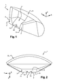
- an optical lens 1 according to the invention comprises a first input diopter 2, a second input diopter 3, an intermediate reflecting diopter 4 and an output diopter 5.
- the first input diopter 2 is constituted by a planar face inscribed in a transverse and vertical plane YZ, and whose longitudinal axis extends in a transverse direction Y and horizontal.
- This face 2 is constituted by a central portion 6 of low height and extending horizontally, said central portion 6 being extended at each of its two ends by an enlarged trapezoidal portion 7, projecting in height.
- the central portion 6 comprises a central protuberance 20 of rounded shape and projecting also in height.
- This first input diopter 2 constitutes the rearmost part of the optical lens 1.
- the exit diopter 5 is for example a surface of ellipsoidal shape having a double curvature: a first curvature in a horizontal plane XY as shown by FIGS. figures 2 and 4 , and a second curvature in a vertical and longitudinal plane XZ as shown by figures 3 and 6 . More precisely, this output dioptre 5 constitutes an ellipsoid portion, of which a first focus F1 is situated at the level of the first input diopter 2 and whose second focus F2 is positioned within this output diopter 5. This diopter 5 is the foremost part of the optical lens 1.
- the center of the output diopter 5 considered along a transverse axis Y and the center of the first input diopter 2 considered along a transverse axis Y, are aligned along a longitudinal axis X. More specifically, the lens 1 has a plane of symmetry vertical and longitudinal, passing through the points materializing said centers.
- the second input diopter 3 is materialized by a rectangular face 8 and horizontal, and whose long side is parallel to a transverse axis Y.
- the length of a large side of this rectangular face 8 is equal to the length of the first diopter input 2 considered along a transverse axis Y, and including the central portion 6 and the two trapezoidal portions 7.
- the first 2 and the second 3 diopter input 2 are perpendicular, the second dioptre 3 constituting the lower part of the lens 1.
- the reflecting intermediate diopter 4 is represented by an inclined wall that can be either rigorously flat, with a slight relief.
- This wall 4 is substantially rectangular, the two long sides defining said wall 4 extending along a transverse axis Y, and the short sides being in planes forming an angle of the order of 45 ° with a vertical YZ plane.
- This intermediate diopter 4 originates at the level of the horizontal upper edge of the central portion 6 of the first input diopter 2 and extends towards the front of the lens 1, towards the exit diopter 5.
- the second diopter of input 3 and the intermediate diopter 4 are placed on either side of the optical axis of the first input diopter 1, said axis passing through a focus of said first diopter 2.
- the intermediate diopter 4 and the output diopter 5 are arranged between them so as to create a focus at the second input diopter 3.
- the first input diopter 2 constitutes the rearmost part of the lens 1 and the output dioptre 5 its foremost part, the intermediate diopter 4 and the second input diopter 3 being positioned between said first diopter 2 and said output diopter 5.
- the intermediate diopter 4 is placed above the second input diopter 3.
- the various diopters 2,3,4,5 are interconnected by means of transparent surfaces having no influence on the optical properties of the lens 1.
- the reflective properties of the intermediate diopter 4 can be improved by means of aluminum deposition.
- a lighting device comprises an optical lens 1 according to the invention, three first electroluminescent diodes 9, 10, 11 capable of emitting light towards the first input diopter 2, as well as two second diodes 12 , 13 electroluminescent capable of emitting light towards the second dioptre 3 input.
- a light-emitting diode will be called LED ( Light Emitting Diode).
- the two second LEDs 12, 13 are arranged on the second input diopter 3, symmetrically with respect to a vertical and longitudinal plane XZ intersecting said second diopter 3 at its center.
- the light beams emitted 14 by said diodes 12,13 through the second input diopter 3, first reach the intermediate diopter 4, before being reflected towards the output diopter 5, then to be transmitted by said exit diopter 5 in parallel light beams.
- the two second LEDs 12, 13 are placed at the centers of the second input diopter 3 defined by the intermediate diopter 4 and the output diopter 5.
- the parallel beams transmitted by the output diopter 5 and which are emitted by the two second LEDs 12,13 placed at the foci of the second input diopter 3, are directed downwards, under a horizontal cutoff, to provide a smoothing function. vehicle lighting.
- a lighting device comprises three first LED 9,10,11 able to emit light towards the first input diopter 2.
- One of these three LEDs is located centrally on said first input diopter 2, at the central protuberance 20 of the central portion 6 of said diopter 2.
- this first central LED 9 is placed at a focus of the first input diopter 2, so that the beams 15 that it emits and which pass through the first input diopter 2 are directly sent to the output diopter 5 which transmits them in beams of parallel light rays in a vertical plane.
- the parallel light beams coming from the first central LED 9 and which are transmitted by the output diopter 5 are directed downwards, under a horizontal cutoff, to provide a lighting function of the vehicle.
- the other two first LEDs 10,11 are arranged on the first input diopter 2, at the two trapezoidal end portions 7.
- these first two LEDs 10,11 are arranged laterally on the first input diopter 2, and symmetrically with respect to the central LED 9, the height of said lateral LEDs 10,11 being lower than that of the central LED 9 .
- the light beams 16 emitted by the first two LEDs 10, 11 in lateral position and which pass through the first input diopter 2, are sent directly to the output diopter 5, which transmits them towards the front of the lens 1.
- the light beams 16 coming from the first two lateral LEDs 10, 11 and which are transmitted by the exit diopter 5, are directed both upwards and downwards, on either side of a horizontal cut, to provide a vehicle day signaling function.
- the overall light beam produced by a lighting device according to the invention could be illustrated by a final diagram which would result from the superimposition of the three diagrams of the Figures 7,8 and 9 .
- a lighting device by virtue of three first LEDs 9, 10, 11 capable of sending light towards the first input diopter 2 and thanks to two LEDs 12, 13 capable of send light to the second input diopter 3, can provide a lighting function and a vehicle day signaling function using a single optical lens 1.
- a projector P according to the invention is schematically illustrated, with a housing B closed by a wall G, passing the beam emitted by the device 1 according to the invention.
- This wall G is in particular a transparent ice. This scheme is generally applicable to the projector according to the invention.
Landscapes
- Engineering & Computer Science (AREA)
- General Engineering & Computer Science (AREA)
- Physics & Mathematics (AREA)
- Microelectronics & Electronic Packaging (AREA)
- Optics & Photonics (AREA)
- Non-Portable Lighting Devices Or Systems Thereof (AREA)
Applications Claiming Priority (1)
| Application Number | Priority Date | Filing Date | Title |
|---|---|---|---|
| FR1355832A FR3007501B1 (fr) | 2013-06-20 | 2013-06-20 | Dispositif d'eclairage d'un vehicule utilisant une lentille optique multifonction |
Publications (2)
| Publication Number | Publication Date |
|---|---|
| EP2816277A1 true EP2816277A1 (de) | 2014-12-24 |
| EP2816277B1 EP2816277B1 (de) | 2015-11-04 |
Family
ID=49237350
Family Applications (1)
| Application Number | Title | Priority Date | Filing Date |
|---|---|---|---|
| EP14172985.5A Active EP2816277B1 (de) | 2013-06-20 | 2014-06-18 | Beleuchtungsvorrichtung eines Fahrzeugs, die eine optische Multifunktionslinse verwendet |
Country Status (2)
| Country | Link |
|---|---|
| EP (1) | EP2816277B1 (de) |
| FR (1) | FR3007501B1 (de) |
Cited By (3)
| Publication number | Priority date | Publication date | Assignee | Title |
|---|---|---|---|---|
| FR3032517A1 (fr) * | 2015-02-05 | 2016-08-12 | Valeo Vision | Dispositif lumineux de vehicule |
| WO2019229191A1 (fr) * | 2018-06-01 | 2019-12-05 | Valeo Vision | Module lumineux pour véhicule automobile, et dispositif d'éclairage et/ou de signalisation muni d'un tel module |
| CN113390066A (zh) * | 2020-03-12 | 2021-09-14 | 维尼亚尔系统公司 | 透镜、包括这种透镜的工作灯以及车辆 |
Families Citing this family (2)
| Publication number | Priority date | Publication date | Assignee | Title |
|---|---|---|---|---|
| KR102171391B1 (ko) * | 2017-01-19 | 2020-10-29 | 하스코 비전 테크놀로지 컴퍼니 리미티드 | Adb 기능이 있는 led 광원 하이-로우 빔 일체형 차량용 램프 모듈 |
| EP4650652A1 (de) * | 2024-05-17 | 2025-11-19 | T.Y.C. Brother Industrial Co., Ltd. | Fahrzeuglichtvorrichtung |
Citations (3)
| Publication number | Priority date | Publication date | Assignee | Title |
|---|---|---|---|---|
| DE102007052696A1 (de) * | 2007-01-11 | 2008-07-17 | Zizala Lichtsysteme Gmbh | Totalreflexionsoptik-System für einen Scheinwerfer oder eine Lichteinheit eines Kraftfahrzeuges |
| EP1965126A1 (de) * | 2007-02-28 | 2008-09-03 | Valeo Vision | Scheinwerfer für Kraftfahrzeug |
| EP2525142A2 (de) | 2011-05-17 | 2012-11-21 | Valeo Vision | Optische Einheit, insbesondere für Kraftfahrzeug |
-
2013
- 2013-06-20 FR FR1355832A patent/FR3007501B1/fr not_active Expired - Fee Related
-
2014
- 2014-06-18 EP EP14172985.5A patent/EP2816277B1/de active Active
Patent Citations (3)
| Publication number | Priority date | Publication date | Assignee | Title |
|---|---|---|---|---|
| DE102007052696A1 (de) * | 2007-01-11 | 2008-07-17 | Zizala Lichtsysteme Gmbh | Totalreflexionsoptik-System für einen Scheinwerfer oder eine Lichteinheit eines Kraftfahrzeuges |
| EP1965126A1 (de) * | 2007-02-28 | 2008-09-03 | Valeo Vision | Scheinwerfer für Kraftfahrzeug |
| EP2525142A2 (de) | 2011-05-17 | 2012-11-21 | Valeo Vision | Optische Einheit, insbesondere für Kraftfahrzeug |
Cited By (9)
| Publication number | Priority date | Publication date | Assignee | Title |
|---|---|---|---|---|
| FR3032517A1 (fr) * | 2015-02-05 | 2016-08-12 | Valeo Vision | Dispositif lumineux de vehicule |
| WO2019229191A1 (fr) * | 2018-06-01 | 2019-12-05 | Valeo Vision | Module lumineux pour véhicule automobile, et dispositif d'éclairage et/ou de signalisation muni d'un tel module |
| FR3081969A1 (fr) * | 2018-06-01 | 2019-12-06 | Valeo Vision | Module lumineux pour vehicule automobile, et dispositif d'eclairage et/ou de signalisation muni d'un tel module |
| CN112219062A (zh) * | 2018-06-01 | 2021-01-12 | 法雷奥照明公司 | 用于机动车辆的照明模块,以及设有这种模块的照明和/或发信号装置 |
| US11421845B2 (en) | 2018-06-01 | 2022-08-23 | Valeo Vision | Light module for motor vehicle, and lighting and/or signaling device provided with such a module |
| CN113390066A (zh) * | 2020-03-12 | 2021-09-14 | 维尼亚尔系统公司 | 透镜、包括这种透镜的工作灯以及车辆 |
| EP3879170A1 (de) * | 2020-03-12 | 2021-09-15 | Vignal Systems | Linse, arbeitsleuchte, die eine solche linse umfasst, und fahrzeug |
| FR3108181A1 (fr) * | 2020-03-12 | 2021-09-17 | Vignal Systems | Lentille, feu de travail comportant une telle lentille, et véhicule |
| US11384914B2 (en) | 2020-03-12 | 2022-07-12 | Vignal Systems | Lens, work light including such a lens, and vehicle |
Also Published As
| Publication number | Publication date |
|---|---|
| FR3007501A1 (fr) | 2014-12-26 |
| FR3007501B1 (fr) | 2015-07-31 |
| EP2816277B1 (de) | 2015-11-04 |
Similar Documents
| Publication | Publication Date | Title |
|---|---|---|
| EP3803198B1 (de) | Lichtmodul für ein automobil-fahrzeug | |
| FR3050011A1 (fr) | Module d'emission d'un faisceau lumineux pour projecteur de vehicule automobile | |
| EP2733413B1 (de) | Optisches Modul für KFZ-Scheinwerfer | |
| FR2868510A1 (fr) | Lampe d'eclairage a diodes electroluminescentes pour vehicule | |
| EP2816277B1 (de) | Beleuchtungsvorrichtung eines Fahrzeugs, die eine optische Multifunktionslinse verwendet | |
| FR3032778A1 (fr) | Feu de vehicule | |
| FR3026461A1 (fr) | Module lumineux pour l'eclairage et/ou la signalisation d'un vehicule automobile | |
| FR2995967B1 (fr) | Module d'eclairage, notamment pour vehicule automobile | |
| EP3521692B1 (de) | Bifunktions-leuchtmodul mit gemeinsamer beleuchteter fläche | |
| EP2846081B1 (de) | Vorrichtung zur Beleuchtung und Signalisierung für Fahrzeuge | |
| EP2436968B1 (de) | Vorrichtung zur Ausstrahlung von Licht für einen Autoscheinwerfer | |
| WO2017025440A1 (fr) | Dispositif d'eclairage et/ou de signalisation pour vehicule automobile | |
| EP3728939A1 (de) | Lichtsignalvorrichtung für ein kraftfahrzeug mit verbessertem sichtkomfort für verkehrsteilnehmer | |
| WO2014083262A1 (fr) | Dispositif de signalisation pour véhicule avec effet tridimensionnel | |
| EP3124856B1 (de) | Beleuchtungsvorrichtung für kraftfahrzeug | |
| FR2928717A1 (fr) | Dispositif d'eclairage pour vehicule automobile. | |
| FR3052535A1 (fr) | Module optique pour dispositif d'eclairage de vehicule automobile | |
| EP3628914B1 (de) | Optische bifunktionseinheit zum anzeigen und beleuchten | |
| WO2024061970A1 (fr) | Module lumineux | |
| FR3141749A1 (fr) | Dispositif d’éclairage | |
| WO2024133261A1 (fr) | Dispositif d'eclairage pour vehicule automobile | |
| FR3063796A1 (fr) | Dispositif d'eclairage pour un faisceau lumineux avec une zone centrale assombrie | |
| FR3144252A1 (fr) | Dispositif d’éclairage | |
| WO2024133404A1 (fr) | Dispositif lumineux comprenant une pluralité de modules |
Legal Events
| Date | Code | Title | Description |
|---|---|---|---|
| PUAI | Public reference made under article 153(3) epc to a published international application that has entered the european phase |
Free format text: ORIGINAL CODE: 0009012 |
|
| 17P | Request for examination filed |
Effective date: 20140618 |
|
| AK | Designated contracting states |
Kind code of ref document: A1 Designated state(s): AL AT BE BG CH CY CZ DE DK EE ES FI FR GB GR HR HU IE IS IT LI LT LU LV MC MK MT NL NO PL PT RO RS SE SI SK SM TR |
|
| AX | Request for extension of the european patent |
Extension state: BA ME |
|
| R17P | Request for examination filed (corrected) |
Effective date: 20150325 |
|
| RBV | Designated contracting states (corrected) |
Designated state(s): AL AT BE BG CH CY CZ DE DK EE ES FI FR GB GR HR HU IE IS IT LI LT LU LV MC MK MT NL NO PL PT RO RS SE SI SK SM TR |
|
| GRAP | Despatch of communication of intention to grant a patent |
Free format text: ORIGINAL CODE: EPIDOSNIGR1 |
|
| INTG | Intention to grant announced |
Effective date: 20150527 |
|
| GRAS | Grant fee paid |
Free format text: ORIGINAL CODE: EPIDOSNIGR3 |
|
| GRAA | (expected) grant |
Free format text: ORIGINAL CODE: 0009210 |
|
| AK | Designated contracting states |
Kind code of ref document: B1 Designated state(s): AL AT BE BG CH CY CZ DE DK EE ES FI FR GB GR HR HU IE IS IT LI LT LU LV MC MK MT NL NO PL PT RO RS SE SI SK SM TR |
|
| REG | Reference to a national code |
Ref country code: GB Ref legal event code: FG4D Free format text: NOT ENGLISH |
|
| REG | Reference to a national code |
Ref country code: CH Ref legal event code: EP |
|
| REG | Reference to a national code |
Ref country code: AT Ref legal event code: REF Ref document number: 759463 Country of ref document: AT Kind code of ref document: T Effective date: 20151115 |
|
| REG | Reference to a national code |
Ref country code: IE Ref legal event code: FG4D Free format text: LANGUAGE OF EP DOCUMENT: FRENCH |
|
| REG | Reference to a national code |
Ref country code: DE Ref legal event code: R096 Ref document number: 602014000421 Country of ref document: DE |
|
| REG | Reference to a national code |
Ref country code: NL Ref legal event code: MP Effective date: 20151104 |
|
| REG | Reference to a national code |
Ref country code: LT Ref legal event code: MG4D |
|
| REG | Reference to a national code |
Ref country code: AT Ref legal event code: MK05 Ref document number: 759463 Country of ref document: AT Kind code of ref document: T Effective date: 20151104 |
|
| PG25 | Lapsed in a contracting state [announced via postgrant information from national office to epo] |
Ref country code: NL Free format text: LAPSE BECAUSE OF FAILURE TO SUBMIT A TRANSLATION OF THE DESCRIPTION OR TO PAY THE FEE WITHIN THE PRESCRIBED TIME-LIMIT Effective date: 20151104 Ref country code: NO Free format text: LAPSE BECAUSE OF FAILURE TO SUBMIT A TRANSLATION OF THE DESCRIPTION OR TO PAY THE FEE WITHIN THE PRESCRIBED TIME-LIMIT Effective date: 20160204 Ref country code: IS Free format text: LAPSE BECAUSE OF FAILURE TO SUBMIT A TRANSLATION OF THE DESCRIPTION OR TO PAY THE FEE WITHIN THE PRESCRIBED TIME-LIMIT Effective date: 20160304 Ref country code: LT Free format text: LAPSE BECAUSE OF FAILURE TO SUBMIT A TRANSLATION OF THE DESCRIPTION OR TO PAY THE FEE WITHIN THE PRESCRIBED TIME-LIMIT Effective date: 20151104 Ref country code: IT Free format text: LAPSE BECAUSE OF FAILURE TO SUBMIT A TRANSLATION OF THE DESCRIPTION OR TO PAY THE FEE WITHIN THE PRESCRIBED TIME-LIMIT Effective date: 20151104 Ref country code: HR Free format text: LAPSE BECAUSE OF FAILURE TO SUBMIT A TRANSLATION OF THE DESCRIPTION OR TO PAY THE FEE WITHIN THE PRESCRIBED TIME-LIMIT Effective date: 20151104 Ref country code: ES Free format text: LAPSE BECAUSE OF FAILURE TO SUBMIT A TRANSLATION OF THE DESCRIPTION OR TO PAY THE FEE WITHIN THE PRESCRIBED TIME-LIMIT Effective date: 20151104 |
|
| PG25 | Lapsed in a contracting state [announced via postgrant information from national office to epo] |
Ref country code: LV Free format text: LAPSE BECAUSE OF FAILURE TO SUBMIT A TRANSLATION OF THE DESCRIPTION OR TO PAY THE FEE WITHIN THE PRESCRIBED TIME-LIMIT Effective date: 20151104 Ref country code: SE Free format text: LAPSE BECAUSE OF FAILURE TO SUBMIT A TRANSLATION OF THE DESCRIPTION OR TO PAY THE FEE WITHIN THE PRESCRIBED TIME-LIMIT Effective date: 20151104 Ref country code: FI Free format text: LAPSE BECAUSE OF FAILURE TO SUBMIT A TRANSLATION OF THE DESCRIPTION OR TO PAY THE FEE WITHIN THE PRESCRIBED TIME-LIMIT Effective date: 20151104 Ref country code: GR Free format text: LAPSE BECAUSE OF FAILURE TO SUBMIT A TRANSLATION OF THE DESCRIPTION OR TO PAY THE FEE WITHIN THE PRESCRIBED TIME-LIMIT Effective date: 20160205 Ref country code: AT Free format text: LAPSE BECAUSE OF FAILURE TO SUBMIT A TRANSLATION OF THE DESCRIPTION OR TO PAY THE FEE WITHIN THE PRESCRIBED TIME-LIMIT Effective date: 20151104 Ref country code: PT Free format text: LAPSE BECAUSE OF FAILURE TO SUBMIT A TRANSLATION OF THE DESCRIPTION OR TO PAY THE FEE WITHIN THE PRESCRIBED TIME-LIMIT Effective date: 20160304 Ref country code: PL Free format text: LAPSE BECAUSE OF FAILURE TO SUBMIT A TRANSLATION OF THE DESCRIPTION OR TO PAY THE FEE WITHIN THE PRESCRIBED TIME-LIMIT Effective date: 20151104 Ref country code: RS Free format text: LAPSE BECAUSE OF FAILURE TO SUBMIT A TRANSLATION OF THE DESCRIPTION OR TO PAY THE FEE WITHIN THE PRESCRIBED TIME-LIMIT Effective date: 20151104 |
|
| REG | Reference to a national code |
Ref country code: FR Ref legal event code: PLFP Year of fee payment: 3 |
|
| PG25 | Lapsed in a contracting state [announced via postgrant information from national office to epo] |
Ref country code: CZ Free format text: LAPSE BECAUSE OF FAILURE TO SUBMIT A TRANSLATION OF THE DESCRIPTION OR TO PAY THE FEE WITHIN THE PRESCRIBED TIME-LIMIT Effective date: 20151104 |
|
| REG | Reference to a national code |
Ref country code: DE Ref legal event code: R097 Ref document number: 602014000421 Country of ref document: DE |
|
| PG25 | Lapsed in a contracting state [announced via postgrant information from national office to epo] |
Ref country code: SK Free format text: LAPSE BECAUSE OF FAILURE TO SUBMIT A TRANSLATION OF THE DESCRIPTION OR TO PAY THE FEE WITHIN THE PRESCRIBED TIME-LIMIT Effective date: 20151104 Ref country code: EE Free format text: LAPSE BECAUSE OF FAILURE TO SUBMIT A TRANSLATION OF THE DESCRIPTION OR TO PAY THE FEE WITHIN THE PRESCRIBED TIME-LIMIT Effective date: 20151104 Ref country code: DK Free format text: LAPSE BECAUSE OF FAILURE TO SUBMIT A TRANSLATION OF THE DESCRIPTION OR TO PAY THE FEE WITHIN THE PRESCRIBED TIME-LIMIT Effective date: 20151104 Ref country code: SM Free format text: LAPSE BECAUSE OF FAILURE TO SUBMIT A TRANSLATION OF THE DESCRIPTION OR TO PAY THE FEE WITHIN THE PRESCRIBED TIME-LIMIT Effective date: 20151104 Ref country code: RO Free format text: LAPSE BECAUSE OF FAILURE TO SUBMIT A TRANSLATION OF THE DESCRIPTION OR TO PAY THE FEE WITHIN THE PRESCRIBED TIME-LIMIT Effective date: 20151104 |
|
| PLBE | No opposition filed within time limit |
Free format text: ORIGINAL CODE: 0009261 |
|
| STAA | Information on the status of an ep patent application or granted ep patent |
Free format text: STATUS: NO OPPOSITION FILED WITHIN TIME LIMIT |
|
| 26N | No opposition filed |
Effective date: 20160805 |
|
| PG25 | Lapsed in a contracting state [announced via postgrant information from national office to epo] |
Ref country code: SI Free format text: LAPSE BECAUSE OF FAILURE TO SUBMIT A TRANSLATION OF THE DESCRIPTION OR TO PAY THE FEE WITHIN THE PRESCRIBED TIME-LIMIT Effective date: 20151104 |
|
| PG25 | Lapsed in a contracting state [announced via postgrant information from national office to epo] |
Ref country code: BE Free format text: LAPSE BECAUSE OF NON-PAYMENT OF DUE FEES Effective date: 20160630 |
|
| PG25 | Lapsed in a contracting state [announced via postgrant information from national office to epo] |
Ref country code: MC Free format text: LAPSE BECAUSE OF FAILURE TO SUBMIT A TRANSLATION OF THE DESCRIPTION OR TO PAY THE FEE WITHIN THE PRESCRIBED TIME-LIMIT Effective date: 20151104 |
|
| REG | Reference to a national code |
Ref country code: IE Ref legal event code: MM4A |
|
| PG25 | Lapsed in a contracting state [announced via postgrant information from national office to epo] |
Ref country code: IE Free format text: LAPSE BECAUSE OF NON-PAYMENT OF DUE FEES Effective date: 20160618 |
|
| REG | Reference to a national code |
Ref country code: FR Ref legal event code: PLFP Year of fee payment: 4 |
|
| REG | Reference to a national code |
Ref country code: DE Ref legal event code: R079 Ref document number: 602014000421 Country of ref document: DE Free format text: PREVIOUS MAIN CLASS: F21S0008100000 Ipc: F21S0043000000 |
|
| REG | Reference to a national code |
Ref country code: CH Ref legal event code: PL |
|
| PG25 | Lapsed in a contracting state [announced via postgrant information from national office to epo] |
Ref country code: CH Free format text: LAPSE BECAUSE OF NON-PAYMENT OF DUE FEES Effective date: 20170630 Ref country code: LI Free format text: LAPSE BECAUSE OF NON-PAYMENT OF DUE FEES Effective date: 20170630 |
|
| PG25 | Lapsed in a contracting state [announced via postgrant information from national office to epo] |
Ref country code: HU Free format text: LAPSE BECAUSE OF FAILURE TO SUBMIT A TRANSLATION OF THE DESCRIPTION OR TO PAY THE FEE WITHIN THE PRESCRIBED TIME-LIMIT; INVALID AB INITIO Effective date: 20140618 |
|
| REG | Reference to a national code |
Ref country code: FR Ref legal event code: PLFP Year of fee payment: 5 |
|
| PG25 | Lapsed in a contracting state [announced via postgrant information from national office to epo] |
Ref country code: LU Free format text: LAPSE BECAUSE OF NON-PAYMENT OF DUE FEES Effective date: 20160618 Ref country code: MK Free format text: LAPSE BECAUSE OF FAILURE TO SUBMIT A TRANSLATION OF THE DESCRIPTION OR TO PAY THE FEE WITHIN THE PRESCRIBED TIME-LIMIT Effective date: 20151104 Ref country code: CY Free format text: LAPSE BECAUSE OF FAILURE TO SUBMIT A TRANSLATION OF THE DESCRIPTION OR TO PAY THE FEE WITHIN THE PRESCRIBED TIME-LIMIT Effective date: 20151104 Ref country code: MT Free format text: LAPSE BECAUSE OF FAILURE TO SUBMIT A TRANSLATION OF THE DESCRIPTION OR TO PAY THE FEE WITHIN THE PRESCRIBED TIME-LIMIT Effective date: 20151104 |
|
| PG25 | Lapsed in a contracting state [announced via postgrant information from national office to epo] |
Ref country code: BG Free format text: LAPSE BECAUSE OF FAILURE TO SUBMIT A TRANSLATION OF THE DESCRIPTION OR TO PAY THE FEE WITHIN THE PRESCRIBED TIME-LIMIT Effective date: 20151104 |
|
| PG25 | Lapsed in a contracting state [announced via postgrant information from national office to epo] |
Ref country code: TR Free format text: LAPSE BECAUSE OF FAILURE TO SUBMIT A TRANSLATION OF THE DESCRIPTION OR TO PAY THE FEE WITHIN THE PRESCRIBED TIME-LIMIT Effective date: 20151104 Ref country code: AL Free format text: LAPSE BECAUSE OF FAILURE TO SUBMIT A TRANSLATION OF THE DESCRIPTION OR TO PAY THE FEE WITHIN THE PRESCRIBED TIME-LIMIT Effective date: 20151104 |
|
| GBPC | Gb: european patent ceased through non-payment of renewal fee |
Effective date: 20180618 |
|
| PG25 | Lapsed in a contracting state [announced via postgrant information from national office to epo] |
Ref country code: GB Free format text: LAPSE BECAUSE OF NON-PAYMENT OF DUE FEES Effective date: 20180618 |
|
| P01 | Opt-out of the competence of the unified patent court (upc) registered |
Effective date: 20230528 |
|
| PGFP | Annual fee paid to national office [announced via postgrant information from national office to epo] |
Ref country code: DE Payment date: 20250617 Year of fee payment: 12 |
|
| PGFP | Annual fee paid to national office [announced via postgrant information from national office to epo] |
Ref country code: FR Payment date: 20250630 Year of fee payment: 12 |