EP2816433A2 - Machine de traitement pour le traitement autonome d'une zone de travail attribuée - Google Patents
Machine de traitement pour le traitement autonome d'une zone de travail attribuée Download PDFInfo
- Publication number
- EP2816433A2 EP2816433A2 EP20140169402 EP14169402A EP2816433A2 EP 2816433 A2 EP2816433 A2 EP 2816433A2 EP 20140169402 EP20140169402 EP 20140169402 EP 14169402 A EP14169402 A EP 14169402A EP 2816433 A2 EP2816433 A2 EP 2816433A2
- Authority
- EP
- European Patent Office
- Prior art keywords
- detection unit
- processing machine
- base station
- air flow
- supplied
- Prior art date
- Legal status (The legal status is an assumption and is not a legal conclusion. Google has not performed a legal analysis and makes no representation as to the accuracy of the status listed.)
- Granted
Links
Images




Classifications
-
- G—PHYSICS
- G05—CONTROLLING; REGULATING
- G05D—SYSTEMS FOR CONTROLLING OR REGULATING NON-ELECTRIC VARIABLES
- G05D1/00—Control of position, course, altitude or attitude of land, water, air or space vehicles, e.g. using automatic pilots
- G05D1/02—Control of position or course in two dimensions
- G05D1/021—Control of position or course in two dimensions specially adapted to land vehicles
- G05D1/0231—Control of position or course in two dimensions specially adapted to land vehicles using optical position detecting means
- G05D1/0246—Control of position or course in two dimensions specially adapted to land vehicles using optical position detecting means using a video camera in combination with image processing means
-
- A—HUMAN NECESSITIES
- A01—AGRICULTURE; FORESTRY; ANIMAL HUSBANDRY; HUNTING; TRAPPING; FISHING
- A01D—HARVESTING; MOWING
- A01D34/00—Mowers; Mowing apparatus of harvesters
- A01D34/006—Control or measuring arrangements
- A01D34/008—Control or measuring arrangements for automated or remotely controlled operation
-
- B—PERFORMING OPERATIONS; TRANSPORTING
- B60—VEHICLES IN GENERAL
- B60L—PROPULSION OF ELECTRICALLY-PROPELLED VEHICLES; SUPPLYING ELECTRIC POWER FOR AUXILIARY EQUIPMENT OF ELECTRICALLY-PROPELLED VEHICLES; ELECTRODYNAMIC BRAKE SYSTEMS FOR VEHICLES IN GENERAL; MAGNETIC SUSPENSION OR LEVITATION FOR VEHICLES; MONITORING OPERATING VARIABLES OF ELECTRICALLY-PROPELLED VEHICLES; ELECTRIC SAFETY DEVICES FOR ELECTRICALLY-PROPELLED VEHICLES
- B60L1/00—Supplying electric power to auxiliary equipment of vehicles
- B60L1/003—Supplying electric power to auxiliary equipment of vehicles to auxiliary motors, e.g. for pumps, compressors
-
- B—PERFORMING OPERATIONS; TRANSPORTING
- B60—VEHICLES IN GENERAL
- B60L—PROPULSION OF ELECTRICALLY-PROPELLED VEHICLES; SUPPLYING ELECTRIC POWER FOR AUXILIARY EQUIPMENT OF ELECTRICALLY-PROPELLED VEHICLES; ELECTRODYNAMIC BRAKE SYSTEMS FOR VEHICLES IN GENERAL; MAGNETIC SUSPENSION OR LEVITATION FOR VEHICLES; MONITORING OPERATING VARIABLES OF ELECTRICALLY-PROPELLED VEHICLES; ELECTRIC SAFETY DEVICES FOR ELECTRICALLY-PROPELLED VEHICLES
- B60L1/00—Supplying electric power to auxiliary equipment of vehicles
- B60L1/02—Supplying electric power to auxiliary equipment of vehicles to electric heating circuits
-
- B—PERFORMING OPERATIONS; TRANSPORTING
- B60—VEHICLES IN GENERAL
- B60L—PROPULSION OF ELECTRICALLY-PROPELLED VEHICLES; SUPPLYING ELECTRIC POWER FOR AUXILIARY EQUIPMENT OF ELECTRICALLY-PROPELLED VEHICLES; ELECTRODYNAMIC BRAKE SYSTEMS FOR VEHICLES IN GENERAL; MAGNETIC SUSPENSION OR LEVITATION FOR VEHICLES; MONITORING OPERATING VARIABLES OF ELECTRICALLY-PROPELLED VEHICLES; ELECTRIC SAFETY DEVICES FOR ELECTRICALLY-PROPELLED VEHICLES
- B60L15/00—Methods, circuits, or devices for controlling the traction-motor speed of electrically-propelled vehicles
- B60L15/20—Methods, circuits, or devices for controlling the traction-motor speed of electrically-propelled vehicles for control of the vehicle or its driving motor to achieve a desired performance, e.g. speed, torque, programmed variation of speed
-
- B—PERFORMING OPERATIONS; TRANSPORTING
- B60—VEHICLES IN GENERAL
- B60L—PROPULSION OF ELECTRICALLY-PROPELLED VEHICLES; SUPPLYING ELECTRIC POWER FOR AUXILIARY EQUIPMENT OF ELECTRICALLY-PROPELLED VEHICLES; ELECTRODYNAMIC BRAKE SYSTEMS FOR VEHICLES IN GENERAL; MAGNETIC SUSPENSION OR LEVITATION FOR VEHICLES; MONITORING OPERATING VARIABLES OF ELECTRICALLY-PROPELLED VEHICLES; ELECTRIC SAFETY DEVICES FOR ELECTRICALLY-PROPELLED VEHICLES
- B60L3/00—Electric devices on electrically-propelled vehicles for safety purposes; Monitoring operating variables, e.g. speed, deceleration or energy consumption
- B60L3/0023—Detecting, eliminating, remedying or compensating for drive train abnormalities, e.g. failures within the drive train
- B60L3/0061—Detecting, eliminating, remedying or compensating for drive train abnormalities, e.g. failures within the drive train relating to electrical machines
-
- B—PERFORMING OPERATIONS; TRANSPORTING
- B60—VEHICLES IN GENERAL
- B60L—PROPULSION OF ELECTRICALLY-PROPELLED VEHICLES; SUPPLYING ELECTRIC POWER FOR AUXILIARY EQUIPMENT OF ELECTRICALLY-PROPELLED VEHICLES; ELECTRODYNAMIC BRAKE SYSTEMS FOR VEHICLES IN GENERAL; MAGNETIC SUSPENSION OR LEVITATION FOR VEHICLES; MONITORING OPERATING VARIABLES OF ELECTRICALLY-PROPELLED VEHICLES; ELECTRIC SAFETY DEVICES FOR ELECTRICALLY-PROPELLED VEHICLES
- B60L3/00—Electric devices on electrically-propelled vehicles for safety purposes; Monitoring operating variables, e.g. speed, deceleration or energy consumption
- B60L3/0023—Detecting, eliminating, remedying or compensating for drive train abnormalities, e.g. failures within the drive train
- B60L3/0069—Detecting, eliminating, remedying or compensating for drive train abnormalities, e.g. failures within the drive train relating to the isolation, e.g. ground fault or leak current
-
- B—PERFORMING OPERATIONS; TRANSPORTING
- B60—VEHICLES IN GENERAL
- B60L—PROPULSION OF ELECTRICALLY-PROPELLED VEHICLES; SUPPLYING ELECTRIC POWER FOR AUXILIARY EQUIPMENT OF ELECTRICALLY-PROPELLED VEHICLES; ELECTRODYNAMIC BRAKE SYSTEMS FOR VEHICLES IN GENERAL; MAGNETIC SUSPENSION OR LEVITATION FOR VEHICLES; MONITORING OPERATING VARIABLES OF ELECTRICALLY-PROPELLED VEHICLES; ELECTRIC SAFETY DEVICES FOR ELECTRICALLY-PROPELLED VEHICLES
- B60L50/00—Electric propulsion with power supplied within the vehicle
- B60L50/50—Electric propulsion with power supplied within the vehicle using propulsion power supplied by batteries or fuel cells
- B60L50/52—Electric propulsion with power supplied within the vehicle using propulsion power supplied by batteries or fuel cells characterised by DC-motors
-
- B—PERFORMING OPERATIONS; TRANSPORTING
- B60—VEHICLES IN GENERAL
- B60L—PROPULSION OF ELECTRICALLY-PROPELLED VEHICLES; SUPPLYING ELECTRIC POWER FOR AUXILIARY EQUIPMENT OF ELECTRICALLY-PROPELLED VEHICLES; ELECTRODYNAMIC BRAKE SYSTEMS FOR VEHICLES IN GENERAL; MAGNETIC SUSPENSION OR LEVITATION FOR VEHICLES; MONITORING OPERATING VARIABLES OF ELECTRICALLY-PROPELLED VEHICLES; ELECTRIC SAFETY DEVICES FOR ELECTRICALLY-PROPELLED VEHICLES
- B60L53/00—Methods of charging batteries, specially adapted for electric vehicles; Charging stations or on-board charging equipment therefor; Exchange of energy storage elements in electric vehicles
- B60L53/10—Methods of charging batteries, specially adapted for electric vehicles; Charging stations or on-board charging equipment therefor; Exchange of energy storage elements in electric vehicles characterised by the energy transfer between the charging station and the vehicle
- B60L53/14—Conductive energy transfer
-
- B—PERFORMING OPERATIONS; TRANSPORTING
- B60—VEHICLES IN GENERAL
- B60L—PROPULSION OF ELECTRICALLY-PROPELLED VEHICLES; SUPPLYING ELECTRIC POWER FOR AUXILIARY EQUIPMENT OF ELECTRICALLY-PROPELLED VEHICLES; ELECTRODYNAMIC BRAKE SYSTEMS FOR VEHICLES IN GENERAL; MAGNETIC SUSPENSION OR LEVITATION FOR VEHICLES; MONITORING OPERATING VARIABLES OF ELECTRICALLY-PROPELLED VEHICLES; ELECTRIC SAFETY DEVICES FOR ELECTRICALLY-PROPELLED VEHICLES
- B60L53/00—Methods of charging batteries, specially adapted for electric vehicles; Charging stations or on-board charging equipment therefor; Exchange of energy storage elements in electric vehicles
- B60L53/30—Constructional details of charging stations
- B60L53/35—Means for automatic or assisted adjustment of the relative position of charging devices and vehicles
-
- B—PERFORMING OPERATIONS; TRANSPORTING
- B60—VEHICLES IN GENERAL
- B60L—PROPULSION OF ELECTRICALLY-PROPELLED VEHICLES; SUPPLYING ELECTRIC POWER FOR AUXILIARY EQUIPMENT OF ELECTRICALLY-PROPELLED VEHICLES; ELECTRODYNAMIC BRAKE SYSTEMS FOR VEHICLES IN GENERAL; MAGNETIC SUSPENSION OR LEVITATION FOR VEHICLES; MONITORING OPERATING VARIABLES OF ELECTRICALLY-PROPELLED VEHICLES; ELECTRIC SAFETY DEVICES FOR ELECTRICALLY-PROPELLED VEHICLES
- B60L58/00—Methods or circuit arrangements for monitoring or controlling batteries or fuel cells, specially adapted for electric vehicles
- B60L58/10—Methods or circuit arrangements for monitoring or controlling batteries or fuel cells, specially adapted for electric vehicles for monitoring or controlling batteries
- B60L58/18—Methods or circuit arrangements for monitoring or controlling batteries or fuel cells, specially adapted for electric vehicles for monitoring or controlling batteries of two or more battery modules
- B60L58/21—Methods or circuit arrangements for monitoring or controlling batteries or fuel cells, specially adapted for electric vehicles for monitoring or controlling batteries of two or more battery modules having the same nominal voltage
-
- B—PERFORMING OPERATIONS; TRANSPORTING
- B60—VEHICLES IN GENERAL
- B60L—PROPULSION OF ELECTRICALLY-PROPELLED VEHICLES; SUPPLYING ELECTRIC POWER FOR AUXILIARY EQUIPMENT OF ELECTRICALLY-PROPELLED VEHICLES; ELECTRODYNAMIC BRAKE SYSTEMS FOR VEHICLES IN GENERAL; MAGNETIC SUSPENSION OR LEVITATION FOR VEHICLES; MONITORING OPERATING VARIABLES OF ELECTRICALLY-PROPELLED VEHICLES; ELECTRIC SAFETY DEVICES FOR ELECTRICALLY-PROPELLED VEHICLES
- B60L58/00—Methods or circuit arrangements for monitoring or controlling batteries or fuel cells, specially adapted for electric vehicles
- B60L58/10—Methods or circuit arrangements for monitoring or controlling batteries or fuel cells, specially adapted for electric vehicles for monitoring or controlling batteries
- B60L58/24—Methods or circuit arrangements for monitoring or controlling batteries or fuel cells, specially adapted for electric vehicles for monitoring or controlling batteries for controlling the temperature of batteries
- B60L58/27—Methods or circuit arrangements for monitoring or controlling batteries or fuel cells, specially adapted for electric vehicles for monitoring or controlling batteries for controlling the temperature of batteries by heating
-
- G—PHYSICS
- G02—OPTICS
- G02B—OPTICAL ELEMENTS, SYSTEMS OR APPARATUS
- G02B27/00—Optical systems or apparatus not provided for by any of the groups G02B1/00 - G02B26/00, G02B30/00
- G02B27/0006—Optical systems or apparatus not provided for by any of the groups G02B1/00 - G02B26/00, G02B30/00 with means to keep optical surfaces clean, e.g. by preventing or removing dirt, stains, contamination, condensation
-
- B—PERFORMING OPERATIONS; TRANSPORTING
- B60—VEHICLES IN GENERAL
- B60L—PROPULSION OF ELECTRICALLY-PROPELLED VEHICLES; SUPPLYING ELECTRIC POWER FOR AUXILIARY EQUIPMENT OF ELECTRICALLY-PROPELLED VEHICLES; ELECTRODYNAMIC BRAKE SYSTEMS FOR VEHICLES IN GENERAL; MAGNETIC SUSPENSION OR LEVITATION FOR VEHICLES; MONITORING OPERATING VARIABLES OF ELECTRICALLY-PROPELLED VEHICLES; ELECTRIC SAFETY DEVICES FOR ELECTRICALLY-PROPELLED VEHICLES
- B60L2200/00—Type of vehicles
- B60L2200/40—Working vehicles
-
- B—PERFORMING OPERATIONS; TRANSPORTING
- B60—VEHICLES IN GENERAL
- B60L—PROPULSION OF ELECTRICALLY-PROPELLED VEHICLES; SUPPLYING ELECTRIC POWER FOR AUXILIARY EQUIPMENT OF ELECTRICALLY-PROPELLED VEHICLES; ELECTRODYNAMIC BRAKE SYSTEMS FOR VEHICLES IN GENERAL; MAGNETIC SUSPENSION OR LEVITATION FOR VEHICLES; MONITORING OPERATING VARIABLES OF ELECTRICALLY-PROPELLED VEHICLES; ELECTRIC SAFETY DEVICES FOR ELECTRICALLY-PROPELLED VEHICLES
- B60L2240/00—Control parameters of input or output; Target parameters
- B60L2240/10—Vehicle control parameters
- B60L2240/36—Temperature of vehicle components or parts
-
- B—PERFORMING OPERATIONS; TRANSPORTING
- B60—VEHICLES IN GENERAL
- B60L—PROPULSION OF ELECTRICALLY-PROPELLED VEHICLES; SUPPLYING ELECTRIC POWER FOR AUXILIARY EQUIPMENT OF ELECTRICALLY-PROPELLED VEHICLES; ELECTRODYNAMIC BRAKE SYSTEMS FOR VEHICLES IN GENERAL; MAGNETIC SUSPENSION OR LEVITATION FOR VEHICLES; MONITORING OPERATING VARIABLES OF ELECTRICALLY-PROPELLED VEHICLES; ELECTRIC SAFETY DEVICES FOR ELECTRICALLY-PROPELLED VEHICLES
- B60L2240/00—Control parameters of input or output; Target parameters
- B60L2240/60—Navigation input
- B60L2240/66—Ambient conditions
- B60L2240/662—Temperature
-
- B—PERFORMING OPERATIONS; TRANSPORTING
- B60—VEHICLES IN GENERAL
- B60L—PROPULSION OF ELECTRICALLY-PROPELLED VEHICLES; SUPPLYING ELECTRIC POWER FOR AUXILIARY EQUIPMENT OF ELECTRICALLY-PROPELLED VEHICLES; ELECTRODYNAMIC BRAKE SYSTEMS FOR VEHICLES IN GENERAL; MAGNETIC SUSPENSION OR LEVITATION FOR VEHICLES; MONITORING OPERATING VARIABLES OF ELECTRICALLY-PROPELLED VEHICLES; ELECTRIC SAFETY DEVICES FOR ELECTRICALLY-PROPELLED VEHICLES
- B60L2240/00—Control parameters of input or output; Target parameters
- B60L2240/60—Navigation input
- B60L2240/66—Ambient conditions
- B60L2240/667—Precipitation
-
- B—PERFORMING OPERATIONS; TRANSPORTING
- B60—VEHICLES IN GENERAL
- B60L—PROPULSION OF ELECTRICALLY-PROPELLED VEHICLES; SUPPLYING ELECTRIC POWER FOR AUXILIARY EQUIPMENT OF ELECTRICALLY-PROPELLED VEHICLES; ELECTRODYNAMIC BRAKE SYSTEMS FOR VEHICLES IN GENERAL; MAGNETIC SUSPENSION OR LEVITATION FOR VEHICLES; MONITORING OPERATING VARIABLES OF ELECTRICALLY-PROPELLED VEHICLES; ELECTRIC SAFETY DEVICES FOR ELECTRICALLY-PROPELLED VEHICLES
- B60L2260/00—Operating Modes
- B60L2260/20—Drive modes; Transition between modes
- B60L2260/32—Auto pilot mode
-
- Y—GENERAL TAGGING OF NEW TECHNOLOGICAL DEVELOPMENTS; GENERAL TAGGING OF CROSS-SECTIONAL TECHNOLOGIES SPANNING OVER SEVERAL SECTIONS OF THE IPC; TECHNICAL SUBJECTS COVERED BY FORMER USPC CROSS-REFERENCE ART COLLECTIONS [XRACs] AND DIGESTS
- Y02—TECHNOLOGIES OR APPLICATIONS FOR MITIGATION OR ADAPTATION AGAINST CLIMATE CHANGE
- Y02T—CLIMATE CHANGE MITIGATION TECHNOLOGIES RELATED TO TRANSPORTATION
- Y02T10/00—Road transport of goods or passengers
- Y02T10/60—Other road transportation technologies with climate change mitigation effect
- Y02T10/64—Electric machine technologies in electromobility
-
- Y—GENERAL TAGGING OF NEW TECHNOLOGICAL DEVELOPMENTS; GENERAL TAGGING OF CROSS-SECTIONAL TECHNOLOGIES SPANNING OVER SEVERAL SECTIONS OF THE IPC; TECHNICAL SUBJECTS COVERED BY FORMER USPC CROSS-REFERENCE ART COLLECTIONS [XRACs] AND DIGESTS
- Y02—TECHNOLOGIES OR APPLICATIONS FOR MITIGATION OR ADAPTATION AGAINST CLIMATE CHANGE
- Y02T—CLIMATE CHANGE MITIGATION TECHNOLOGIES RELATED TO TRANSPORTATION
- Y02T10/00—Road transport of goods or passengers
- Y02T10/60—Other road transportation technologies with climate change mitigation effect
- Y02T10/70—Energy storage systems for electromobility, e.g. batteries
-
- Y—GENERAL TAGGING OF NEW TECHNOLOGICAL DEVELOPMENTS; GENERAL TAGGING OF CROSS-SECTIONAL TECHNOLOGIES SPANNING OVER SEVERAL SECTIONS OF THE IPC; TECHNICAL SUBJECTS COVERED BY FORMER USPC CROSS-REFERENCE ART COLLECTIONS [XRACs] AND DIGESTS
- Y02—TECHNOLOGIES OR APPLICATIONS FOR MITIGATION OR ADAPTATION AGAINST CLIMATE CHANGE
- Y02T—CLIMATE CHANGE MITIGATION TECHNOLOGIES RELATED TO TRANSPORTATION
- Y02T10/00—Road transport of goods or passengers
- Y02T10/60—Other road transportation technologies with climate change mitigation effect
- Y02T10/7072—Electromobility specific charging systems or methods for batteries, ultracapacitors, supercapacitors or double-layer capacitors
-
- Y—GENERAL TAGGING OF NEW TECHNOLOGICAL DEVELOPMENTS; GENERAL TAGGING OF CROSS-SECTIONAL TECHNOLOGIES SPANNING OVER SEVERAL SECTIONS OF THE IPC; TECHNICAL SUBJECTS COVERED BY FORMER USPC CROSS-REFERENCE ART COLLECTIONS [XRACs] AND DIGESTS
- Y02—TECHNOLOGIES OR APPLICATIONS FOR MITIGATION OR ADAPTATION AGAINST CLIMATE CHANGE
- Y02T—CLIMATE CHANGE MITIGATION TECHNOLOGIES RELATED TO TRANSPORTATION
- Y02T10/00—Road transport of goods or passengers
- Y02T10/60—Other road transportation technologies with climate change mitigation effect
- Y02T10/72—Electric energy management in electromobility
-
- Y—GENERAL TAGGING OF NEW TECHNOLOGICAL DEVELOPMENTS; GENERAL TAGGING OF CROSS-SECTIONAL TECHNOLOGIES SPANNING OVER SEVERAL SECTIONS OF THE IPC; TECHNICAL SUBJECTS COVERED BY FORMER USPC CROSS-REFERENCE ART COLLECTIONS [XRACs] AND DIGESTS
- Y02—TECHNOLOGIES OR APPLICATIONS FOR MITIGATION OR ADAPTATION AGAINST CLIMATE CHANGE
- Y02T—CLIMATE CHANGE MITIGATION TECHNOLOGIES RELATED TO TRANSPORTATION
- Y02T90/00—Enabling technologies or technologies with a potential or indirect contribution to GHG emissions mitigation
- Y02T90/10—Technologies relating to charging of electric vehicles
- Y02T90/12—Electric charging stations
-
- Y—GENERAL TAGGING OF NEW TECHNOLOGICAL DEVELOPMENTS; GENERAL TAGGING OF CROSS-SECTIONAL TECHNOLOGIES SPANNING OVER SEVERAL SECTIONS OF THE IPC; TECHNICAL SUBJECTS COVERED BY FORMER USPC CROSS-REFERENCE ART COLLECTIONS [XRACs] AND DIGESTS
- Y02—TECHNOLOGIES OR APPLICATIONS FOR MITIGATION OR ADAPTATION AGAINST CLIMATE CHANGE
- Y02T—CLIMATE CHANGE MITIGATION TECHNOLOGIES RELATED TO TRANSPORTATION
- Y02T90/00—Enabling technologies or technologies with a potential or indirect contribution to GHG emissions mitigation
- Y02T90/10—Technologies relating to charging of electric vehicles
- Y02T90/14—Plug-in electric vehicles
-
- Y—GENERAL TAGGING OF NEW TECHNOLOGICAL DEVELOPMENTS; GENERAL TAGGING OF CROSS-SECTIONAL TECHNOLOGIES SPANNING OVER SEVERAL SECTIONS OF THE IPC; TECHNICAL SUBJECTS COVERED BY FORMER USPC CROSS-REFERENCE ART COLLECTIONS [XRACs] AND DIGESTS
- Y02—TECHNOLOGIES OR APPLICATIONS FOR MITIGATION OR ADAPTATION AGAINST CLIMATE CHANGE
- Y02T—CLIMATE CHANGE MITIGATION TECHNOLOGIES RELATED TO TRANSPORTATION
- Y02T90/00—Enabling technologies or technologies with a potential or indirect contribution to GHG emissions mitigation
- Y02T90/10—Technologies relating to charging of electric vehicles
- Y02T90/16—Information or communication technologies improving the operation of electric vehicles
Definitions
- the present invention relates to a processing machine for the autonomous processing of an associated work area, with a detection unit for detecting current environmental parameters that can be evaluated for controlling the processing machine in the associated work area.
- This autonomous lawnmower is provided with a camera-type detection unit for detecting, in operation of the autonomous lawnmower, current environmental parameters that are evaluable to provide suitable control of the autonomous lawnmower, e.g. to allow navigation on the lawn.
- a disadvantage of the prior art is that during operation of such an autonomous lawnmower operational pollution and / or fogging of the camera and / or condensation on the camera can lead to a limitation of the functionality of the camera. Such a limitation can lead to a limited and erroneous detection of the current environmental parameters and thus to an imprecise and incorrect control of the autonomous lawnmower.
- An object of the invention is therefore to provide a new processing machine for the autonomous processing of an associated work area, which has a detection unit, with each of the current environmental parameters can be detected safely and reliably.
- a processing machine for the autonomous processing of an associated work area with a detection unit for detecting current environmental parameters that can be evaluated to control the processing machine in the associated work area.
- the detection unit is associated with a free-hold device, which is at least adapted to at least reduce operating-related contamination and / or fogging of the detection unit and / or condensation on the detection unit in the autonomous operation of the processing machine.
- the invention thus makes it possible to provide a processing machine for the autonomous processing of an associated work area, in which an operational contamination and / or fogging of an associated detection unit and / or condensation on the detection unit in the operation of the processing machine by a use of the free-hold device in a simple manner at least substantially safe and reliable can be prevented.
- the detection unit has at least one camera and / or at least one optical sensor.
- the environmental parameters preferably include localization, desktop recognition and / or background detection parameters.
- navigation data and / or suitable work surface or substrate-specific processing data for controlling the processing machine can be determined in a simple manner.
- the free-hold device has at least one air guiding device, which is supplied with airflow at least in the autonomous operation of the processing machine.
- the air guiding device is designed to guide the supplied air flow at least partially in the direction of the detection unit.
- the invention thus makes it possible to provide a processing machine with a simple and uncomplicated free-hold device.
- the at least partially directed in the direction of the detection unit air flow is at least designed to at least substantially prevent settling of dirt and / or water particles on the detection unit and / or to cool the detection unit at least in sections.
- the free-hold device has at least one fan wheel for generating the supplied air flow.
- the supplied air flow can be generated in a simple manner.
- a drive motor is provided for driving in the autonomous operation of the processing machine, which is assigned to the engine cooling at least one fan, which is adapted to generate the supplied air flow at least partially.
- a fan wheel already provided as an integral part of the processing machine can be used to generate the supplied air flow, so that a space-saving and resource-saving implementation of the present invention is made possible.
- At least one battery pack is provided for the power supply in the autonomous operation of the processing machine, for cooling purposes at least one fan wheel is assigned, which is designed to generate the supplied air flow at least partially.
- the invention thus makes it possible to provide a battery-operated processing machine in which a fan wheel already provided as an integral part of an associated battery pack can be used to generate the supplied air flow, so that a space-saving and resource-saving implementation of the present invention is also made possible in this embodiment.
- the supplied air flow from the drive motor and / or battery pack is heated.
- the drive motor can be energized to allow heating of the drive motor and / or the battery pack for heating the supplied air flow.
- the air flow can be heated in a simple manner.
- the processing machine is designed in the manner of an autonomous lawnmower or an autonomous vacuum cleaner.
- an autonomous lawn mower or vacuum cleaner is merely exemplary in nature and is not to be construed as limiting the invention, which may apply to other autonomous work machines, e.g. in an autonomous windscreen wiper.
- a base station for a processing unit provided with a detection unit for autonomously processing an associated work area, wherein the detection unit is designed to detect each current environmental parameters that are evaluable for controlling the processing machine in an associated work area, wherein a cleaning device is provided, which is at least adapted to contamination and / or fogging of the detection unit and / or condensation on the detection unit at least reduce.
- the invention thus makes it possible to provide a base station with a cleaning device for a processing machine, with a contamination and / or fogging of a processing unit associated detection unit and / or condensation on this detection unit before and / or after operation of the machine easily Way at least substantially safe and reliable can be reduced.
- the cleaning device is associated with at least one fan for generating an at least partially the detection unit can be supplied to the air flow.
- the detection unit can be safely and reliably cleaned.
- an efficient cooling of the detection unit can be made possible.
- the air flow is at least designed to at least substantially prevent the settling of dirt and / or water particles on the detection unit of the processing machine and / or to cool the detection unit at least in sections.
- the cleaning device is associated with at least one air duct, which is adapted to direct the at least partially the detection unit can be supplied to the air flow to the detection unit.
- the air flow can be passed accurately and precisely to the detection unit.
- a bottom plate is provided, in which the air duct is arranged.
- the air duct can be easily and safely placed in the base station.
- the cleaning device is associated with a heat source for generating heat.
- heat can be provided in a simple manner, at least for reducing a fitting of the detection unit associated with the processing machine.
- a bottom plate is provided, in which the heat source is arranged.
- the heat source can be safely and reliably placed in the base station.
- the heat source is preferably designed in the manner of a heating mat.
- the heat source is preferably designed for heating the air flow, which can be supplied at least partially to the detection unit.
- a heated air flow can be provided in a simple manner.
- the base station is preferably designed to provide energy for the processing machine in order to enable at least charging of a battery pack assigned to the processing machine.
- the battery pack can be safely and reliably charged in the base station.
- a system having at least: a processing machine for autonomous processing of an associated work area, with a detection unit for detecting current environmental parameters, which are evaluable for controlling the processing machine in the associated work area, and a base station for the processing machine, which is designed at least to at least reduce soiling and / or fogging of the detection unit and / or condensation on the detection unit.
- the invention thus also makes it possible to provide a system consisting of a processing machine described above and a base station for the processing machine described above.
- FIG. 10 shows an example processing machine 100 for autonomously processing an associated workspace 110 according to the present invention.
- the processing machine 100 has a machine housing 102 provided with at least one air inlet opening 107, which can be moved autonomously in the working area 110, for example via at least three wheels and / or rollers 103, 104, 105.
- the air inlet opening 107 may be provided, for example, with a grid and / or a filter.
- the processing machine 100 has a processing unit 106 for processing the working area 110, which can be activated illustratively via an on / off switch 108.
- processing unit 106 activation of the processing unit 106 by operation of the on / off switch 108 is merely exemplary in nature and should not be considered as limiting the invention. Rather, the processing unit 106 may also be activated in any other manner, e.g. by means of a remote control or automatically upon introduction of the processing machine 100 into the associated working area 110.
- the processing machine 100 preferably has at least one detection unit 120 arranged on the machine housing 102 for detecting respectively current environmental parameters, which preferably comprise at least localization, work surface recognition and / or background recognition parameters. These respective current environmental parameters are preferably evaluable at least for controlling the processing machine 100 in the associated working area 110, in order to achieve this, for example. Navigation data and / or suitable Hä inhabitg. Substrate specific machining data to determine. A corresponding evaluation can take place via a suitable control unit in any manner known to the person skilled in the art and, like the suitable control unit, is not the subject matter of the present invention. Therefore, for the sake of brevity, the description is omitted here for a detailed description thereof.
- the detection unit 120 is assigned at least one free-hold device 150.
- This is preferably designed at least to operate in the autonomous operation of the processing machine 100 Contamination of the detection unit 120, at least to reduce fogging of the detection unit 120 and / or condensation on the detection unit 120 and preferably substantially completely prevented.
- the free-hold device 150 preferably has at least one air guiding device 152, which is designed at least to guide an air flow 154 in the direction of the detection unit 120 during operation of the processing machine 100, which flows around it at least in sections.
- the air guiding device 152 surrounds the detection unit 120 in an illustrative annular manner and in this case forms an annular air outlet opening in the region of the detection unit 120.
- the air guide 152 may also form one or more punctiform air outlet openings.
- the airflow 154 may be directed in any direction via the detection unit 120.
- the airflow 154 may also be jerked over the detection unit 120, including e.g. On the air guide 152, a suitable valve or a suitable slide can be provided.
- the processing machine 100 is designed in the manner of an autonomous lawnmower and is therefore also referred to below as "robotic lawnmower" for the purpose of simplifying the description.
- the processing unit 106 is formed in the manner of a lawn mowing apparatus, wherein the associated work area 110 represents a lawn.
- the robotic lawnmower 100 is described by way of example only and not for the purpose of illustrating one possible embodiment of the present invention. Rather, it can be applied quite generally to autonomous processing machines where the detection unit 120 is used, e.g. for autonomous vacuum cleaners, autonomous windscreen wipers, etc.
- the robotic lawnmower 100 is preferably battery operated and provided with a suitable battery pack, as in Fig. 4 and 7 described. It should be understood, however, that the present invention is not limited to electrically driven, and in particular battery powered, robotic lawnmowers, but rather is generally applicable to autonomous processing machines, whether electrically or non-electrically drivable.
- Fig. 2 shows the mowing robot 100 provided with the processing unit 106 Fig. 1 who like at Fig. 1 described the machine housing 102 and the detection unit 120 disposed thereon.
- This is designed according to a first embodiment in the manner of an image detection unit 220, in particular in the manner of a camera, which is preferably at least partially integrated into the machine housing 102 and in the area provided with the louver 152 free-hold device 150 of Fig. 1 is provided.
- the processing unit 106 is as in Fig. 1 described in the manner of a lawn mowing device and accordingly has illustratively one or more mower blades 208, to the drive in the autonomous operation of the robotic lawnmower 100, a drive motor 206 is provided. At least one fan wheel 207 is associated with this for engine cooling, which, for example, can suck in air through the air inlet opening 107 provided on the machine housing 102 in order to generate a cooling air stream 209 flowing past at least on the outer circumference of the drive motor 206.
- an air deflection device 210 is provided, which is arranged illustratively in the machine housing 102 and is adapted to divert at least a portion of an air flow generated by the fan 207, or a portion of the cooling air flow 209, to the air guide 152 of the free-hold device 150.
- the free-hold device 150 can be supplied with an air flow marked 212 in the operation of the robotic lawnmower 100. Therefore, the fan 207 is illustratively associated with the blanking device 150 as well.
- the fan wheel 207 at least partially generates the free air device 150 supplied air stream 212. This is at least partially directed by the air guide 152 as the air flow 154 in the direction of the camera 220 to flow around them at least partially, and thus a setting of Dirt and / or water particles on the camera 120 to reduce at least and preferably at least substantially prevented.
- the free flow device 150 supplied air flow 212 and thus the air flow 154 is preferably heated by the drive motor 206 and thus, in particular, can effectively prevent fogging of the camera 220.
- Fig. 3 shows the mowing robot 100 provided with the processing unit 106 Fig. 1 who has the camera 220 of Fig. 2 having.
- the free-space device 150 has a separate fan wheel 310 for the at least partial generation of an airflow 312 supplied to the air-guiding device 152, so that the use of the fan wheel 207 of FIG Fig. 2 can be omitted and this is thus optional in the second embodiment.
- the fan 310 may be used to generate the airflow 312, e.g. Suck in air via the air inlet opening 107 of the machine housing 102.
- the air flow 312 is at least partially directed by the air guiding device 152 as the air flow 154 in the direction of the camera 220 in order to flow around it at least in regions.
- the air flow 154 may cool the camera 220 at least in sections.
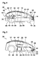
- Fig. 4 shows the mowing robot 100 provided with the processing unit 106 Fig. 1 who has the camera 220 of Fig. 2 having.
- the robotic lawnmower 100 is battery-operated here and has at least one battery pack 450 for autonomous power supply, which is provided with a plurality of battery cells 452 by way of example.
- At least one fan impeller 460 is associated with this battery pack 450, which according to a third embodiment is designed to at least partially generate an airflow 412 supplied to the air conduction device 152, so that the use of the fan impeller 207 of FIG Fig. 2 can be omitted and this is thus optional in the third embodiment. Therefore, the fan 460 is illustratively associated with the blanking device 150 as well.
- the fan wheel 460 for generating the air flow 412 for example, air via the air inlet opening 107 of the machine housing 102, or an additional provided thereon air inlet opening 402, suck, as indicated by an arrow 462.
- the air stream 412 is supplied, for example, via an air duct 410 to the air guiding device 152 and is at least partially conducted by the latter as the air stream 154 in the direction of the camera 220, to flow around this at least partially.
- the air flow 412 and thus the air flow 154 are preferably heated by the battery pack 450 and can thus effectively prevent fogging of the camera 220 in particular.
- Fig. 5 shows that with the Fig. 2 described processing unit 106 provided mower robot 100 of Fig. 1 who like at Fig. 1 described the machine housing 102 and the detection unit 120 disposed thereon.
- This has, according to a second embodiment, at least one and illustratively two optical sensors 522, 524, which are preferably at least partially integrated into the machine housing 102 and in their area the provided with an alternative air guide 552 free-hold device 150 of Fig. 1 is provided.
- an air deflection device 510 is provided, which is arranged illustratively in the machine housing 102 and designed to divert at least a portion of an air flow generated by the fan 207, or a portion of the cooling air flow 209, to the air guide 552 of the free-hold device 150.
- the freestanding device 150 can be supplied with an air flow marked 512 in the operation of the robotic lawnmower 100.
- the fan wheel 207 at least partially generates the air flow 512 supplied to the free-hold device 150.
- the latter is guided by the air-guiding device 552 at least partially as air flow 554 in the direction of the optical sensors 522, 524 in order to flow around them at least in regions and thus Stopping of dirt and / or water particles on the optical sensors 522, 524 at least to reduce and preferably at least substantially prevented.
- the air flow 512 supplied to the free-hold device 150 and thus the air flow 554 are preferably heated by the drive motor 206 and can thus effectively prevent fogging of the optical sensors 522, 524 in particular.
- Fig. 6 shows the robotic lawnmower 100 of Fig. 5 having the optical sensors 522, 524.
- the free-space device 150 according to a fifth embodiment has a separate fan wheel 610 for at least partially generating one of the air-guiding device 552 supplied air flow 612, so that a use of the fan 207 of Fig. 5 can be omitted and this is thus optional in the fifth embodiment.
- the fan 610 may be used to generate the air flow 612, e.g. Suck in air via the air inlet opening 107 of the machine housing 102.
- the air flow 612 is at least partially directed by the air guide device 552 as the air flow 154 in the direction of the optical sensors 522, 524 in order to flow around them at least in regions.
- the air flow 554 can cool the optical sensors 522, 524 at least in sections.
- Fig. 7 shows the robotic lawnmower 100 of Fig. 5 comprising the optical sensors 522, 524 of Fig. 5 having.
- the robotic lawnmower 100 is battery-operated here and has at least one battery pack 750 for autonomous power supply, which is provided with a plurality of battery cells 752 by way of example.
- At least one fan wheel 760 which according to a sixth embodiment is designed to at least partially generate an air flow 712 supplied to the air guide device 552, is assigned to this battery pack 750 for cooling, so that the use of the fan wheel 207 of FIG Fig. 5 can be omitted and this is thus optional in the sixth embodiment. Therefore, the fan 760 is illustratively associated with the blanking device 150 as well.
- the fan 760 may be used to generate the airflow 712, e.g. Air via the air inlet opening 107 of the machine housing 102, or an additional thereto provided air inlet opening 702, suck, as indicated by an arrow 762.
- the air stream 712 is e.g. supplied via an air duct 710 of the louver 552 and from this at least partially as the air flow 554 in the direction of the optical sensors 522, 524 passed to flow around them at least partially.
- the air flow 712 and thus the air flow 554 are preferably heated by the battery pack 750 and can thus effectively prevent fogging of the optical sensors 522, 524 in particular.
- the robotic lawnmower 100 for detecting water particles on the detection unit 120 or the optical sensors 522, 524 may be preferred have a moisture detection device. This can be designed, for example, in the manner of a temperature sensor and / or a rain sensor.
- the optical sensors 522, 524 can detect fogging eg by no, a very weak or a very untypical signal from the transmitter to the receiver itself.
- the optical sensors 522, 524 may output corrupted readings if their temperature is too high during operation.
- the robotic lawnmower 100 or the free-space device 150 of the robotic lawnmower 100 according to a seven embodiment with a fan (1170 in Fig.
- This cooling air flow (1171, 1172 in Fig. 10 ) for generating a cooling air flow (1171, 1172 in Fig. 10 ), eg at high ambient temperatures, as may be the case for example in midsummer.
- This cooling air flow (1171, 1172 in Fig. 10 ) is preferably designed for cooling the optical sensors 522, 524 and / or the drive motor 206 and / or the battery pack 750 and / or any other temperature-sensitive part of the robotic lawnmower 100.
- the drive motor 206 of the robotic lawnmower 100 is preferably designed such that it is preferably energized without commissioning the robotic lawnmower 100 to allow heating of the drive motor 206 and / or the battery pack 450, 750 for heating the supplied air flow 212, 412.
- the robotic lawnmower 206 pauses and the drive motor 206 is energized in a targeted manner, eg a motor output stage assigned to the drive motor 206 can be heated by slow switching.
- the heating of the drive motor 206 by a Bremsbestromung in which the drive motor 206 is heated by constant rapid reversal of the motor rotation direction, can be generated.
- the generated heat can then be conducted to the optical sensors 522, 524 with the aid of the fan wheel 207 assigned to the drive motor 206 and thus at least reduce the occurring water particles.
- the energization is not limited to the drive motor 206, but rather can be done on any, the robotic lawnmower 100 associated engine, for example on a Radantriebsmotor.
- FIG. 3 shows the robotic lawnmower 100 of FIG. 1 in a base station 1100 in an exemplary parking and / or charging position, which is hereinafter referred to simply as a parking position for the sake of simplicity Fig. 5 ,
- the robotic lawnmower 100 and the base station 1100 preferably form a system 1500.
- the robotic lawnmower 100 is located between two operations in the base station 1100.
- the battery pack 750 can preferably be charged and / or the optical sensors 522, 524 are cleaned.
- a contamination and / or water particles on the optical sensors 522, 524 may optionally be as described above, e.g. be detected by a temperature sensor and / or a rain sensor.
- the base station 1100 may have at its bottom plate 1110 in the region of the optical sensors 522, 524 a reflector surface with a known reflectance, via which a contamination and / or water particles on the optical sensors 522, 524 can be determined.
- Fig. 8 For example, such contamination and / or fogging of the optical sensors 522, 524 will occur by way of example with the aid of the heat generated by the drive motor 206, which is analogous to, for example Fig. 5 is passed with a fan 207 to the optical sensors 522, 524, at least reduced.
- the drive motor 206 is designed such that it can be operated in the parking position analogously to autonomous operation or analogously to Fig. 7 can be energized.
- the drive motor 206 can optionally be supplied via the battery pack 750 of the robotic lawnmower 100 or via the base station 1100, which is preferably designed to provide energy for the robotic lawnmower 100.
- Fig. 9 shows that in the base station 1100 of Fig. 8 parking robots 100 of Fig. 7 , Analogous to Fig. 7
- contamination and / or fogging of the detection unit 120 is at least reduced by means of the heat generated by the battery pack 750 of the robotic lawnmower 100 and at least partially conducted to the optical sensors 522, 524 by the fan wheel 760.
- the battery pack 750 is preferably heated via a specific charging process, which is preferably completed or completed before the following operation of the robotic lawnmower 100.
- the battery pack 750 via a targeted Overloading which is finished, for example, shortly before the following operation of the robotic lawnmower 100 and is performed in the non-battery-damaging area, are heated.
- Fig. 10 shows that in the base station 1100 of Fig. 8 parking robots 100 of Fig. 7 with a free-hold device 150 designed according to the seventh embodiment, in which, between the battery pack 750 and the optical sensors 522, 524, an impeller 1170 is illustratively arranged for generating a cooling air flow 1171, 1172 preferably conducted in the air duct 710.
- This fan 1170 may optionally or additionally eg at and / or before operation in warm or hot ambient temperatures, eg. B. on high summer days, for cooling the battery pack 750 and / or for cooling the optical sensors 522, 524 application, so that at such high temperatures possible corruption of measured values can be prevented.
- Fig. 11 shows the robotic lawnmower 100 of Fig. 7 in the base station 1100 of Fig. 8 , which according to a second embodiment has an air duct 1125.
- the air duct 1125 is disposed in the bottom plate 1110 of the base station 1100 and directs an analogous to the air flow 712 of Fig. 7 heated air flow 1127 preferably at least partially to the optical sensors 522, 524.
- the air flow 1127 for this purpose on an underside 1126 of the robotic lawnmower 100 preferably in the range of a wheel 103, 104, 105 of the robotic lawnmower 100 discharged and via the air duct 1127 to the passed optical sensors 522, 524.
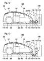
- Fig. 12 shows the robotic lawnmower 100 with the detection unit 120 of FIG Fig. 5 and the base station 1100 of Fig. 8 , which according to a third embodiment comprises a cleaning device 1102.
- the cleaning device 1102 is designed at least to at least reduce fouling and / or fogging of the optical sensors 522, 524 and / or condensation on the optical sensors 522, 524.
- the cleaning device 1102 preferably has at least one fan 1120 for generating an air flow 1131, 1132, 1133 which can be supplied at least partially to the optical sensors 522, 524.
- This air flow 1131, 1132, 1133 is at least designed to settle dirt and / or water particles on the optical sensors 522, 524 of the robotic lawnmower 100 at least substantially to prevent and / or to cool the optical sensors 522, 524 at least in sections.
- the cleaning device 1102 preferably has a heat source 1140 for generating heat.
- This heat source 1140 is preferably designed to heat the air stream 1131, 1132, 1133 which can be supplied at least partially to the optical sensors 522, 524 and is preferably arranged in the region of the optical sensors 522, 524.
- Fig. 13 shows the robotic lawnmower 100 with the detection unit 120 of FIG Fig. 5 and the base station 1100 of Fig. 12 ,
- the at least partially the optical sensors 522, 524 feedable air flow 1131, 1132 in Fig. 13 analogous to at least one air duct 1125 of Fig. 11 via at least one preferably in the bottom plate 1110 of the base station 1100 arranged air duct 1327 directed to the detection unit 120.
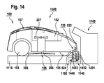
- Fig. 14 shows the robotic lawnmower 100 with the detection unit 120 of FIG Fig. 5 and the base station 1100 of Fig. 8 according to a fourth embodiment comprising a heat source 1140 arranged in the bottom plate 1110 of the base station 1100.
- the heat source 1140 is configured to generate rising heat 1431, 1432, 1433, which reduces at least one of soiling and / or condensing the optical sensors 522, 524.
- a heating of the bottom plate 1110 in the region of the battery pack 750 can take place, by means of which the usable power of the robotic lawnmower 100 battery capacity of the battery pack 750 can be preferably increased.
- the heat source 1140 is designed as a heating mat 1440.
- the detection unit 120 is realized in each case either with an image acquisition unit, in particular a camera, or with optical sensors.
- the invention is not limited to such detection units, but can be used in a variety of other detection units application, eg in ToF (Time of Flight) cameras, ultrasonic sensors, laser sensors, lighting elements such as LEDs, etc.
- processing machine 100 and / or the base station 1100 can also be combined with one another as desired.
Landscapes
- Engineering & Computer Science (AREA)
- Power Engineering (AREA)
- Transportation (AREA)
- Mechanical Engineering (AREA)
- Life Sciences & Earth Sciences (AREA)
- Physics & Mathematics (AREA)
- Sustainable Development (AREA)
- Sustainable Energy (AREA)
- General Physics & Mathematics (AREA)
- Radar, Positioning & Navigation (AREA)
- Computer Vision & Pattern Recognition (AREA)
- Multimedia (AREA)
- Electromagnetism (AREA)
- Aviation & Aerospace Engineering (AREA)
- Remote Sensing (AREA)
- Automation & Control Theory (AREA)
- Environmental Sciences (AREA)
- Optics & Photonics (AREA)
- Harvester Elements (AREA)
- Control Of Position, Course, Altitude, Or Attitude Of Moving Bodies (AREA)
Applications Claiming Priority (2)
| Application Number | Priority Date | Filing Date | Title |
|---|---|---|---|
| DE102013211339 | 2013-06-18 | ||
| DE201410204091 DE102014204091A1 (de) | 2013-06-18 | 2014-03-06 | Bearbeitungsmaschine zur autonomen Bearbeitung eines zugeordneten Arbeitsbereichs |
Publications (3)
| Publication Number | Publication Date |
|---|---|
| EP2816433A2 true EP2816433A2 (fr) | 2014-12-24 |
| EP2816433A3 EP2816433A3 (fr) | 2015-09-30 |
| EP2816433B1 EP2816433B1 (fr) | 2020-10-21 |
Family
ID=50771131
Family Applications (1)
| Application Number | Title | Priority Date | Filing Date |
|---|---|---|---|
| EP14169402.6A Active EP2816433B1 (fr) | 2013-06-18 | 2014-05-22 | Machine de traitement pour le traitement autonome d'une zone de travail attribuée |
Country Status (3)
| Country | Link |
|---|---|
| EP (1) | EP2816433B1 (fr) |
| CN (1) | CN104221575B (fr) |
| DE (1) | DE102014204091A1 (fr) |
Cited By (11)
| Publication number | Priority date | Publication date | Assignee | Title |
|---|---|---|---|---|
| CN105940870A (zh) * | 2016-06-13 | 2016-09-21 | 常州格力博有限公司 | 动力头及其割草机 |
| CN106659346A (zh) * | 2014-07-04 | 2017-05-10 | 东芝生活电器株式会社 | 电动吸尘器 |
| DE102017100672A1 (de) | 2017-01-16 | 2018-07-19 | Connaught Electronics Ltd. | Kameravorrichtung für ein Kraftfahrzeug mit Reinigungseinrichtung zum Bereitstellen des Luftstroms, Kamerasystem sowie Kraftfahrzeug |
| EP3430880A4 (fr) * | 2016-03-17 | 2019-02-27 | Honda Motor Co., Ltd. | Engin de chantier déplaçable sans conducteur |
| DE102018216123A1 (de) * | 2018-09-21 | 2020-03-26 | Robert Bosch Gmbh | Sensoreinheit mit Reinigungsfunktion |
| US10691000B2 (en) | 2015-07-17 | 2020-06-23 | Positec Power Tools (Suzhou) Co., Ltd. | Autonomous moving device |
| DE112016001913B4 (de) | 2015-12-28 | 2022-03-17 | Fujitsu Ten Limited | Fremdmaterial-Beseitigungsgerät |
| EP3950412A4 (fr) * | 2019-03-28 | 2022-04-20 | Honda Motor Co., Ltd. | Machine de travail à déplacement autonome et station de charge |
| US20220201936A1 (en) * | 2020-12-29 | 2022-06-30 | Agco Corporation | Skid plate for sensor integration |
| DE102021006363A1 (de) | 2021-01-13 | 2022-07-14 | Husqvarna Ab | Eine Roboterarbeitsvorrichtung mit verbesserter Kühlung |
| US11490566B2 (en) | 2019-04-08 | 2022-11-08 | Honda Motor Co., Ltd. | Apparatus and method for cooling lawnmower components |
Families Citing this family (8)
| Publication number | Priority date | Publication date | Assignee | Title |
|---|---|---|---|---|
| DE102015221658A1 (de) | 2015-11-04 | 2017-05-04 | Robert Bosch Gmbh | Gartensensorvorrichtung |
| DE102016115321A1 (de) * | 2016-08-18 | 2018-02-22 | Vorwerk & Co. Interholding Gmbh | Serviceeinrichtung für ein Feuchtreinigungsgerät |
| US9807930B1 (en) * | 2016-08-25 | 2017-11-07 | Irobot Corporation | Blade guard for a robot lawnmower |
| JP2020068895A (ja) * | 2018-10-29 | 2020-05-07 | 大成建設株式会社 | 清掃ロボット |
| CN112327705B (zh) * | 2020-11-12 | 2021-12-31 | 浙江工业大学 | 一种基于铜丝溶断的智能小车停车控制系统、方法 |
| CN113276080B (zh) * | 2021-05-20 | 2022-11-11 | 杭州海康威视数字技术股份有限公司 | 底盘模组和移动机器人 |
| US20240280675A1 (en) * | 2023-02-20 | 2024-08-22 | Apple Inc. | Sensor system |
| DE102023202646B4 (de) | 2023-03-23 | 2024-10-10 | BSH Hausgeräte GmbH | Reinigung eines Bodenroboters |
Family Cites Families (9)
| Publication number | Priority date | Publication date | Assignee | Title |
|---|---|---|---|---|
| DE10012004A1 (de) * | 2000-03-11 | 2001-09-27 | Bosch Gmbh Robert | Einrichtung zum Sauberhalten optischer Elemente in Kraftfahrzeugen, insbesondere von Sensor- oder Kamera-Abdeckungen |
| US6496754B2 (en) * | 2000-11-17 | 2002-12-17 | Samsung Kwangju Electronics Co., Ltd. | Mobile robot and course adjusting method thereof |
| DE10225151A1 (de) * | 2002-06-06 | 2003-12-18 | Bosch Gmbh Robert | Vorrichtung zur Vermeidung von Ablagerungen von Partikeln/Substanzen auf einem empfindlichen optischen Gerät, insbesondere einer Sensor-Oberfläche |
| GB0515840D0 (en) * | 2005-08-02 | 2005-09-07 | Bosch Gmbh Robert | Improvements in or relating to braking systems |
| CN101091428A (zh) * | 2006-10-20 | 2007-12-26 | 大连理工大学 | 一种自动割草机器人 |
| NL1036699C2 (nl) * | 2009-03-11 | 2010-09-14 | Lely Patent Nv | Inrichting voor het verrichten van werkzaamheden in een ruimte waarin verontreinigingen kunnen optreden. |
| CN102081232B (zh) * | 2010-11-20 | 2012-11-14 | 山西科达自控工程技术有限公司 | 摄像机镜头气体清洁设备 |
| CN202077380U (zh) * | 2011-04-01 | 2011-12-21 | 上海大学 | 一种gps导航割草机器人 |
| CN202958189U (zh) * | 2012-11-27 | 2013-06-05 | 上海大学 | 智能割草机器人 |
-
2014
- 2014-03-06 DE DE201410204091 patent/DE102014204091A1/de not_active Ceased
- 2014-05-22 EP EP14169402.6A patent/EP2816433B1/fr active Active
- 2014-06-16 CN CN201410268407.2A patent/CN104221575B/zh active Active
Non-Patent Citations (1)
| Title |
|---|
| None |
Cited By (16)
| Publication number | Priority date | Publication date | Assignee | Title |
|---|---|---|---|---|
| CN106659346A (zh) * | 2014-07-04 | 2017-05-10 | 东芝生活电器株式会社 | 电动吸尘器 |
| US10691000B2 (en) | 2015-07-17 | 2020-06-23 | Positec Power Tools (Suzhou) Co., Ltd. | Autonomous moving device |
| DE112016001913B4 (de) | 2015-12-28 | 2022-03-17 | Fujitsu Ten Limited | Fremdmaterial-Beseitigungsgerät |
| EP3430880A4 (fr) * | 2016-03-17 | 2019-02-27 | Honda Motor Co., Ltd. | Engin de chantier déplaçable sans conducteur |
| US10653058B2 (en) | 2016-03-17 | 2020-05-19 | Honda Motor Co., Ltd. | Unmanned operation vehicle |
| CN105940870A (zh) * | 2016-06-13 | 2016-09-21 | 常州格力博有限公司 | 动力头及其割草机 |
| DE102017100672A1 (de) | 2017-01-16 | 2018-07-19 | Connaught Electronics Ltd. | Kameravorrichtung für ein Kraftfahrzeug mit Reinigungseinrichtung zum Bereitstellen des Luftstroms, Kamerasystem sowie Kraftfahrzeug |
| DE102018216123A1 (de) * | 2018-09-21 | 2020-03-26 | Robert Bosch Gmbh | Sensoreinheit mit Reinigungsfunktion |
| WO2020058127A1 (fr) * | 2018-09-21 | 2020-03-26 | Robert Bosch Gmbh | Unité de détection dotée d'une fonction nettoyage |
| EP3950412A4 (fr) * | 2019-03-28 | 2022-04-20 | Honda Motor Co., Ltd. | Machine de travail à déplacement autonome et station de charge |
| US11490566B2 (en) | 2019-04-08 | 2022-11-08 | Honda Motor Co., Ltd. | Apparatus and method for cooling lawnmower components |
| US20220201936A1 (en) * | 2020-12-29 | 2022-06-30 | Agco Corporation | Skid plate for sensor integration |
| US11980131B2 (en) * | 2020-12-29 | 2024-05-14 | Agco Corporation | Skid plate for sensor integration |
| DE102021006363A1 (de) | 2021-01-13 | 2022-07-14 | Husqvarna Ab | Eine Roboterarbeitsvorrichtung mit verbesserter Kühlung |
| SE2150016A1 (en) * | 2021-01-13 | 2022-07-14 | Husqvarna Ab | A robotic work tool with enhanced cooling |
| SE544860C2 (en) * | 2021-01-13 | 2022-12-13 | Husqvarna Ab | A robotic work tool with enhanced cooling |
Also Published As
| Publication number | Publication date |
|---|---|
| CN104221575B (zh) | 2021-06-29 |
| CN104221575A (zh) | 2014-12-24 |
| EP2816433B1 (fr) | 2020-10-21 |
| DE102014204091A1 (de) | 2014-12-18 |
| EP2816433A3 (fr) | 2015-09-30 |
Similar Documents
| Publication | Publication Date | Title |
|---|---|---|
| EP2816433A2 (fr) | Machine de traitement pour le traitement autonome d'une zone de travail attribuée | |
| EP3441842B1 (fr) | Procédé de fonctionnement d'un appareil de traitement du sol mobile automatique | |
| DE102015106536B4 (de) | Haushaltsroboter und Verfahren zum Betreiben eines Haushaltsroboters | |
| EP3412191B1 (fr) | Appareil de traitement du sol se déplaçant automatiquement | |
| EP3454715B1 (fr) | Systeme et procede de nettoyage d'un sol avec un robot de nettoyage | |
| DE102010000607B4 (de) | Als Basisstation für ein selbsttätig verfahrbares Saug- und/oder Kehrgerät einsetzbarer Haushaltsstaubsauger | |
| EP3968621B1 (fr) | Appareil mobile de nettoyage du sol, ainsi que procédé de fonctionnement d'un tel appareil | |
| EP2746681B1 (fr) | Hotte aspirante et procédé de commande du fonctionnement d'une hotte aspirante | |
| EP2946710B1 (fr) | Machine-outil manuelle dotée d'un raccord d'évacuation de particules | |
| EP3416018B1 (fr) | Système pourvu d'au moins deux appareils de traitement du sol | |
| DE102016100489B4 (de) | System und Verfahren zur Luftreinigung an mindestens zwei verschiedenen Orten | |
| EP3047781B1 (fr) | Aspirateur-traîneau à activation autonome, procédé d'aspiration de poussières et utilisation d'un aspirateur-traîneau utilisable à activation autonome | |
| DE102008026884B4 (de) | Reinigungsgerät für Partikel aufweisende Flächen und Verfahren zu dessen Betrieb | |
| DE102016115321A1 (de) | Serviceeinrichtung für ein Feuchtreinigungsgerät | |
| DE102015121972A1 (de) | System und Verfahren zur Bearbeitung eines Bodens mit einer mobilen Robotereinheit | |
| EP3243418B1 (fr) | Système et procédé de nettoyage d'un plancher à l'aide d'un robot de nettoyage | |
| EP2944942A1 (fr) | Appareil de nettoyage à déplacement automatique | |
| DE102016205336A1 (de) | Autonome Vorrichtung zur Behandlung von Unkraut | |
| DE102012109938A1 (de) | Selbsttätig verfahrbares Bodenstaub-Aufsammelgerät, sowie Verfahren zum Betreiben eines solchen Gerätes | |
| DE102015226021A1 (de) | Absaugvorrichtung | |
| DE102007056770A1 (de) | Belüftungs- und/oder Klimatisierungssystem für ein Fahrzeug sowie Verfahren zur Steuerung oder Regelung desselben | |
| DE102019209381A1 (de) | Vorrichtung zum Schutz eines Sensorfensters | |
| DE102018216123A1 (de) | Sensoreinheit mit Reinigungsfunktion | |
| DE102016120362A1 (de) | Reinigungssystem zur zumindest teilweise automatischen Reinigung von wenigstens einem Objekt im Überbodenbereich | |
| DE102018126103A1 (de) | Saugreinigungsgerät mit einem Influenzsensor |
Legal Events
| Date | Code | Title | Description |
|---|---|---|---|
| PUAI | Public reference made under article 153(3) epc to a published international application that has entered the european phase |
Free format text: ORIGINAL CODE: 0009012 |
|
| 17P | Request for examination filed |
Effective date: 20140522 |
|
| AK | Designated contracting states |
Kind code of ref document: A2 Designated state(s): AL AT BE BG CH CY CZ DE DK EE ES FI FR GB GR HR HU IE IS IT LI LT LU LV MC MK MT NL NO PL PT RO RS SE SI SK SM TR |
|
| AX | Request for extension of the european patent |
Extension state: BA ME |
|
| RIC1 | Information provided on ipc code assigned before grant |
Ipc: G02B 27/00 20060101ALI20150430BHEP Ipc: G05D 1/02 20060101AFI20150430BHEP Ipc: B60S 1/54 20060101ALI20150430BHEP Ipc: B60S 1/02 20060101ALI20150430BHEP |
|
| PUAL | Search report despatched |
Free format text: ORIGINAL CODE: 0009013 |
|
| AK | Designated contracting states |
Kind code of ref document: A3 Designated state(s): AL AT BE BG CH CY CZ DE DK EE ES FI FR GB GR HR HU IE IS IT LI LT LU LV MC MK MT NL NO PL PT RO RS SE SI SK SM TR |
|
| AX | Request for extension of the european patent |
Extension state: BA ME |
|
| RIC1 | Information provided on ipc code assigned before grant |
Ipc: G05D 1/02 20060101AFI20150824BHEP Ipc: B60S 1/02 20060101ALI20150824BHEP Ipc: B60S 1/54 20060101ALI20150824BHEP Ipc: G02B 27/00 20060101ALI20150824BHEP |
|
| R17P | Request for examination filed (corrected) |
Effective date: 20160330 |
|
| RBV | Designated contracting states (corrected) |
Designated state(s): AL AT BE BG CH CY CZ DE DK EE ES FI FR GB GR HR HU IE IS IT LI LT LU LV MC MK MT NL NO PL PT RO RS SE SI SK SM TR |
|
| STAA | Information on the status of an ep patent application or granted ep patent |
Free format text: STATUS: EXAMINATION IS IN PROGRESS |
|
| 17Q | First examination report despatched |
Effective date: 20180214 |
|
| RAP1 | Party data changed (applicant data changed or rights of an application transferred) |
Owner name: ROBERT BOSCH GMBH |
|
| GRAP | Despatch of communication of intention to grant a patent |
Free format text: ORIGINAL CODE: EPIDOSNIGR1 |
|
| STAA | Information on the status of an ep patent application or granted ep patent |
Free format text: STATUS: GRANT OF PATENT IS INTENDED |
|
| INTG | Intention to grant announced |
Effective date: 20200504 |
|
| GRAS | Grant fee paid |
Free format text: ORIGINAL CODE: EPIDOSNIGR3 |
|
| GRAA | (expected) grant |
Free format text: ORIGINAL CODE: 0009210 |
|
| STAA | Information on the status of an ep patent application or granted ep patent |
Free format text: STATUS: THE PATENT HAS BEEN GRANTED |
|
| AK | Designated contracting states |
Kind code of ref document: B1 Designated state(s): AL AT BE BG CH CY CZ DE DK EE ES FI FR GB GR HR HU IE IS IT LI LT LU LV MC MK MT NL NO PL PT RO RS SE SI SK SM TR |
|
| REG | Reference to a national code |
Ref country code: GB Ref legal event code: FG4D Free format text: NOT ENGLISH |
|
| REG | Reference to a national code |
Ref country code: CH Ref legal event code: EP |
|
| REG | Reference to a national code |
Ref country code: IE Ref legal event code: FG4D Free format text: LANGUAGE OF EP DOCUMENT: GERMAN |
|
| REG | Reference to a national code |
Ref country code: DE Ref legal event code: R096 Ref document number: 502014014908 Country of ref document: DE |
|
| REG | Reference to a national code |
Ref country code: AT Ref legal event code: REF Ref document number: 1326454 Country of ref document: AT Kind code of ref document: T Effective date: 20201115 |
|
| REG | Reference to a national code |
Ref country code: NL Ref legal event code: MP Effective date: 20201021 |
|
| PG25 | Lapsed in a contracting state [announced via postgrant information from national office to epo] |
Ref country code: RS Free format text: LAPSE BECAUSE OF FAILURE TO SUBMIT A TRANSLATION OF THE DESCRIPTION OR TO PAY THE FEE WITHIN THE PRESCRIBED TIME-LIMIT Effective date: 20201021 Ref country code: FI Free format text: LAPSE BECAUSE OF FAILURE TO SUBMIT A TRANSLATION OF THE DESCRIPTION OR TO PAY THE FEE WITHIN THE PRESCRIBED TIME-LIMIT Effective date: 20201021 Ref country code: PT Free format text: LAPSE BECAUSE OF FAILURE TO SUBMIT A TRANSLATION OF THE DESCRIPTION OR TO PAY THE FEE WITHIN THE PRESCRIBED TIME-LIMIT Effective date: 20210222 Ref country code: NL Free format text: LAPSE BECAUSE OF FAILURE TO SUBMIT A TRANSLATION OF THE DESCRIPTION OR TO PAY THE FEE WITHIN THE PRESCRIBED TIME-LIMIT Effective date: 20201021 Ref country code: NO Free format text: LAPSE BECAUSE OF FAILURE TO SUBMIT A TRANSLATION OF THE DESCRIPTION OR TO PAY THE FEE WITHIN THE PRESCRIBED TIME-LIMIT Effective date: 20210121 Ref country code: GR Free format text: LAPSE BECAUSE OF FAILURE TO SUBMIT A TRANSLATION OF THE DESCRIPTION OR TO PAY THE FEE WITHIN THE PRESCRIBED TIME-LIMIT Effective date: 20210122 |
|
| REG | Reference to a national code |
Ref country code: LT Ref legal event code: MG4D |
|
| PG25 | Lapsed in a contracting state [announced via postgrant information from national office to epo] |
Ref country code: PL Free format text: LAPSE BECAUSE OF FAILURE TO SUBMIT A TRANSLATION OF THE DESCRIPTION OR TO PAY THE FEE WITHIN THE PRESCRIBED TIME-LIMIT Effective date: 20201021 Ref country code: LV Free format text: LAPSE BECAUSE OF FAILURE TO SUBMIT A TRANSLATION OF THE DESCRIPTION OR TO PAY THE FEE WITHIN THE PRESCRIBED TIME-LIMIT Effective date: 20201021 Ref country code: SE Free format text: LAPSE BECAUSE OF FAILURE TO SUBMIT A TRANSLATION OF THE DESCRIPTION OR TO PAY THE FEE WITHIN THE PRESCRIBED TIME-LIMIT Effective date: 20201021 Ref country code: IS Free format text: LAPSE BECAUSE OF FAILURE TO SUBMIT A TRANSLATION OF THE DESCRIPTION OR TO PAY THE FEE WITHIN THE PRESCRIBED TIME-LIMIT Effective date: 20210221 Ref country code: ES Free format text: LAPSE BECAUSE OF FAILURE TO SUBMIT A TRANSLATION OF THE DESCRIPTION OR TO PAY THE FEE WITHIN THE PRESCRIBED TIME-LIMIT Effective date: 20201021 Ref country code: BG Free format text: LAPSE BECAUSE OF FAILURE TO SUBMIT A TRANSLATION OF THE DESCRIPTION OR TO PAY THE FEE WITHIN THE PRESCRIBED TIME-LIMIT Effective date: 20210121 |
|
| PG25 | Lapsed in a contracting state [announced via postgrant information from national office to epo] |
Ref country code: HR Free format text: LAPSE BECAUSE OF FAILURE TO SUBMIT A TRANSLATION OF THE DESCRIPTION OR TO PAY THE FEE WITHIN THE PRESCRIBED TIME-LIMIT Effective date: 20201021 |
|
| REG | Reference to a national code |
Ref country code: DE Ref legal event code: R097 Ref document number: 502014014908 Country of ref document: DE |
|
| PG25 | Lapsed in a contracting state [announced via postgrant information from national office to epo] |
Ref country code: RO Free format text: LAPSE BECAUSE OF FAILURE TO SUBMIT A TRANSLATION OF THE DESCRIPTION OR TO PAY THE FEE WITHIN THE PRESCRIBED TIME-LIMIT Effective date: 20201021 Ref country code: SK Free format text: LAPSE BECAUSE OF FAILURE TO SUBMIT A TRANSLATION OF THE DESCRIPTION OR TO PAY THE FEE WITHIN THE PRESCRIBED TIME-LIMIT Effective date: 20201021 Ref country code: LT Free format text: LAPSE BECAUSE OF FAILURE TO SUBMIT A TRANSLATION OF THE DESCRIPTION OR TO PAY THE FEE WITHIN THE PRESCRIBED TIME-LIMIT Effective date: 20201021 Ref country code: CZ Free format text: LAPSE BECAUSE OF FAILURE TO SUBMIT A TRANSLATION OF THE DESCRIPTION OR TO PAY THE FEE WITHIN THE PRESCRIBED TIME-LIMIT Effective date: 20201021 Ref country code: EE Free format text: LAPSE BECAUSE OF FAILURE TO SUBMIT A TRANSLATION OF THE DESCRIPTION OR TO PAY THE FEE WITHIN THE PRESCRIBED TIME-LIMIT Effective date: 20201021 Ref country code: SM Free format text: LAPSE BECAUSE OF FAILURE TO SUBMIT A TRANSLATION OF THE DESCRIPTION OR TO PAY THE FEE WITHIN THE PRESCRIBED TIME-LIMIT Effective date: 20201021 |
|
| PLBE | No opposition filed within time limit |
Free format text: ORIGINAL CODE: 0009261 |
|
| STAA | Information on the status of an ep patent application or granted ep patent |
Free format text: STATUS: NO OPPOSITION FILED WITHIN TIME LIMIT |
|
| PG25 | Lapsed in a contracting state [announced via postgrant information from national office to epo] |
Ref country code: DK Free format text: LAPSE BECAUSE OF FAILURE TO SUBMIT A TRANSLATION OF THE DESCRIPTION OR TO PAY THE FEE WITHIN THE PRESCRIBED TIME-LIMIT Effective date: 20201021 |
|
| 26N | No opposition filed |
Effective date: 20210722 |
|
| PG25 | Lapsed in a contracting state [announced via postgrant information from national office to epo] |
Ref country code: AL Free format text: LAPSE BECAUSE OF FAILURE TO SUBMIT A TRANSLATION OF THE DESCRIPTION OR TO PAY THE FEE WITHIN THE PRESCRIBED TIME-LIMIT Effective date: 20201021 Ref country code: IT Free format text: LAPSE BECAUSE OF FAILURE TO SUBMIT A TRANSLATION OF THE DESCRIPTION OR TO PAY THE FEE WITHIN THE PRESCRIBED TIME-LIMIT Effective date: 20201021 |
|
| PG25 | Lapsed in a contracting state [announced via postgrant information from national office to epo] |
Ref country code: SI Free format text: LAPSE BECAUSE OF FAILURE TO SUBMIT A TRANSLATION OF THE DESCRIPTION OR TO PAY THE FEE WITHIN THE PRESCRIBED TIME-LIMIT Effective date: 20201021 |
|
| REG | Reference to a national code |
Ref country code: CH Ref legal event code: PL |
|
| GBPC | Gb: european patent ceased through non-payment of renewal fee |
Effective date: 20210522 |
|
| PG25 | Lapsed in a contracting state [announced via postgrant information from national office to epo] |
Ref country code: LI Free format text: LAPSE BECAUSE OF NON-PAYMENT OF DUE FEES Effective date: 20210531 Ref country code: LU Free format text: LAPSE BECAUSE OF NON-PAYMENT OF DUE FEES Effective date: 20210522 Ref country code: MC Free format text: LAPSE BECAUSE OF FAILURE TO SUBMIT A TRANSLATION OF THE DESCRIPTION OR TO PAY THE FEE WITHIN THE PRESCRIBED TIME-LIMIT Effective date: 20201021 Ref country code: CH Free format text: LAPSE BECAUSE OF NON-PAYMENT OF DUE FEES Effective date: 20210531 |
|
| REG | Reference to a national code |
Ref country code: BE Ref legal event code: MM Effective date: 20210531 |
|
| PG25 | Lapsed in a contracting state [announced via postgrant information from national office to epo] |
Ref country code: IE Free format text: LAPSE BECAUSE OF NON-PAYMENT OF DUE FEES Effective date: 20210522 Ref country code: GB Free format text: LAPSE BECAUSE OF NON-PAYMENT OF DUE FEES Effective date: 20210522 |
|
| PG25 | Lapsed in a contracting state [announced via postgrant information from national office to epo] |
Ref country code: IS Free format text: LAPSE BECAUSE OF FAILURE TO SUBMIT A TRANSLATION OF THE DESCRIPTION OR TO PAY THE FEE WITHIN THE PRESCRIBED TIME-LIMIT Effective date: 20210221 Ref country code: FR Free format text: LAPSE BECAUSE OF NON-PAYMENT OF DUE FEES Effective date: 20210531 |
|
| REG | Reference to a national code |
Ref country code: AT Ref legal event code: MM01 Ref document number: 1326454 Country of ref document: AT Kind code of ref document: T Effective date: 20210522 |
|
| PG25 | Lapsed in a contracting state [announced via postgrant information from national office to epo] |
Ref country code: BE Free format text: LAPSE BECAUSE OF NON-PAYMENT OF DUE FEES Effective date: 20210531 |
|
| PG25 | Lapsed in a contracting state [announced via postgrant information from national office to epo] |
Ref country code: AT Free format text: LAPSE BECAUSE OF NON-PAYMENT OF DUE FEES Effective date: 20210522 |
|
| PG25 | Lapsed in a contracting state [announced via postgrant information from national office to epo] |
Ref country code: HU Free format text: LAPSE BECAUSE OF FAILURE TO SUBMIT A TRANSLATION OF THE DESCRIPTION OR TO PAY THE FEE WITHIN THE PRESCRIBED TIME-LIMIT; INVALID AB INITIO Effective date: 20140522 |
|
| PG25 | Lapsed in a contracting state [announced via postgrant information from national office to epo] |
Ref country code: CY Free format text: LAPSE BECAUSE OF FAILURE TO SUBMIT A TRANSLATION OF THE DESCRIPTION OR TO PAY THE FEE WITHIN THE PRESCRIBED TIME-LIMIT Effective date: 20201021 |
|
| REG | Reference to a national code |
Ref country code: DE Ref legal event code: R079 Ref document number: 502014014908 Country of ref document: DE Free format text: PREVIOUS MAIN CLASS: G05D0001020000 Ipc: G05D0001430000 |
|
| REG | Reference to a national code |
Ref country code: DE Ref legal event code: R084 Ref document number: 502014014908 Country of ref document: DE |
|
| PG25 | Lapsed in a contracting state [announced via postgrant information from national office to epo] |
Ref country code: MK Free format text: LAPSE BECAUSE OF FAILURE TO SUBMIT A TRANSLATION OF THE DESCRIPTION OR TO PAY THE FEE WITHIN THE PRESCRIBED TIME-LIMIT Effective date: 20201021 |
|
| PG25 | Lapsed in a contracting state [announced via postgrant information from national office to epo] |
Ref country code: MT Free format text: LAPSE BECAUSE OF FAILURE TO SUBMIT A TRANSLATION OF THE DESCRIPTION OR TO PAY THE FEE WITHIN THE PRESCRIBED TIME-LIMIT Effective date: 20201021 |
|
| PGFP | Annual fee paid to national office [announced via postgrant information from national office to epo] |
Ref country code: DE Payment date: 20250716 Year of fee payment: 12 |
|
| PG25 | Lapsed in a contracting state [announced via postgrant information from national office to epo] |
Ref country code: TR Free format text: LAPSE BECAUSE OF FAILURE TO SUBMIT A TRANSLATION OF THE DESCRIPTION OR TO PAY THE FEE WITHIN THE PRESCRIBED TIME-LIMIT Effective date: 20201021 |