EP2817149B1 - Mehrschichtaufbau als reflektor mit erhöhter mechanischer stabilität - Google Patents
Mehrschichtaufbau als reflektor mit erhöhter mechanischer stabilität Download PDFInfo
- Publication number
- EP2817149B1 EP2817149B1 EP12813338.6A EP12813338A EP2817149B1 EP 2817149 B1 EP2817149 B1 EP 2817149B1 EP 12813338 A EP12813338 A EP 12813338A EP 2817149 B1 EP2817149 B1 EP 2817149B1
- Authority
- EP
- European Patent Office
- Prior art keywords
- layer
- multilayer structure
- structure according
- bis
- und
- Prior art date
- Legal status (The legal status is an assumption and is not a legal conclusion. Google has not performed a legal analysis and makes no representation as to the accuracy of the status listed.)
- Not-in-force
Links
Images

Classifications
-
- C—CHEMISTRY; METALLURGY
- C09—DYES; PAINTS; POLISHES; NATURAL RESINS; ADHESIVES; COMPOSITIONS NOT OTHERWISE PROVIDED FOR; APPLICATIONS OF MATERIALS NOT OTHERWISE PROVIDED FOR
- C09D—COATING COMPOSITIONS, e.g. PAINTS, VARNISHES OR LACQUERS; FILLING PASTES; CHEMICAL PAINT OR INK REMOVERS; INKS; CORRECTING FLUIDS; WOODSTAINS; PASTES OR SOLIDS FOR COLOURING OR PRINTING; USE OF MATERIALS THEREFOR
- C09D5/00—Coating compositions, e.g. paints, varnishes or lacquers, characterised by their physical nature or the effects produced; Filling pastes
- C09D5/08—Anti-corrosive paints
-
- B—PERFORMING OPERATIONS; TRANSPORTING
- B32—LAYERED PRODUCTS
- B32B—LAYERED PRODUCTS, i.e. PRODUCTS BUILT-UP OF STRATA OF FLAT OR NON-FLAT, e.g. CELLULAR OR HONEYCOMB, FORM
- B32B17/00—Layered products essentially comprising sheet glass, or glass, slag, or like fibres
- B32B17/06—Layered products essentially comprising sheet glass, or glass, slag, or like fibres comprising glass as the main or only constituent of a layer, next to another layer of a specific material
- B32B17/10—Layered products essentially comprising sheet glass, or glass, slag, or like fibres comprising glass as the main or only constituent of a layer, next to another layer of a specific material of synthetic resin
- B32B17/10005—Layered products essentially comprising sheet glass, or glass, slag, or like fibres comprising glass as the main or only constituent of a layer, next to another layer of a specific material of synthetic resin laminated safety glass or glazing
- B32B17/10009—Layered products essentially comprising sheet glass, or glass, slag, or like fibres comprising glass as the main or only constituent of a layer, next to another layer of a specific material of synthetic resin laminated safety glass or glazing characterized by the number, the constitution or treatment of glass sheets
- B32B17/10018—Layered products essentially comprising sheet glass, or glass, slag, or like fibres comprising glass as the main or only constituent of a layer, next to another layer of a specific material of synthetic resin laminated safety glass or glazing characterized by the number, the constitution or treatment of glass sheets comprising only one glass sheet
-
- B—PERFORMING OPERATIONS; TRANSPORTING
- B32—LAYERED PRODUCTS
- B32B—LAYERED PRODUCTS, i.e. PRODUCTS BUILT-UP OF STRATA OF FLAT OR NON-FLAT, e.g. CELLULAR OR HONEYCOMB, FORM
- B32B17/00—Layered products essentially comprising sheet glass, or glass, slag, or like fibres
- B32B17/06—Layered products essentially comprising sheet glass, or glass, slag, or like fibres comprising glass as the main or only constituent of a layer, next to another layer of a specific material
- B32B17/10—Layered products essentially comprising sheet glass, or glass, slag, or like fibres comprising glass as the main or only constituent of a layer, next to another layer of a specific material of synthetic resin
- B32B17/10005—Layered products essentially comprising sheet glass, or glass, slag, or like fibres comprising glass as the main or only constituent of a layer, next to another layer of a specific material of synthetic resin laminated safety glass or glazing
- B32B17/10165—Functional features of the laminated safety glass or glazing
- B32B17/10174—Coatings of a metallic or dielectric material on a constituent layer of glass or polymer
-
- C—CHEMISTRY; METALLURGY
- C03—GLASS; MINERAL OR SLAG WOOL
- C03C—CHEMICAL COMPOSITION OF GLASSES, GLAZES OR VITREOUS ENAMELS; SURFACE TREATMENT OF GLASS; SURFACE TREATMENT OF FIBRES OR FILAMENTS MADE FROM GLASS, MINERALS OR SLAGS; JOINING GLASS TO GLASS OR OTHER MATERIALS
- C03C17/00—Surface treatment of glass, not in the form of fibres or filaments, by coating
- C03C17/34—Surface treatment of glass, not in the form of fibres or filaments, by coating with at least two coatings having different compositions
- C03C17/36—Surface treatment of glass, not in the form of fibres or filaments, by coating with at least two coatings having different compositions at least one coating being a metal
-
- C—CHEMISTRY; METALLURGY
- C03—GLASS; MINERAL OR SLAG WOOL
- C03C—CHEMICAL COMPOSITION OF GLASSES, GLAZES OR VITREOUS ENAMELS; SURFACE TREATMENT OF GLASS; SURFACE TREATMENT OF FIBRES OR FILAMENTS MADE FROM GLASS, MINERALS OR SLAGS; JOINING GLASS TO GLASS OR OTHER MATERIALS
- C03C17/00—Surface treatment of glass, not in the form of fibres or filaments, by coating
- C03C17/34—Surface treatment of glass, not in the form of fibres or filaments, by coating with at least two coatings having different compositions
- C03C17/36—Surface treatment of glass, not in the form of fibres or filaments, by coating with at least two coatings having different compositions at least one coating being a metal
- C03C17/3602—Surface treatment of glass, not in the form of fibres or filaments, by coating with at least two coatings having different compositions at least one coating being a metal the metal being present as a layer
- C03C17/3642—Surface treatment of glass, not in the form of fibres or filaments, by coating with at least two coatings having different compositions at least one coating being a metal the metal being present as a layer the multilayer coating containing a metal layer
-
- C—CHEMISTRY; METALLURGY
- C03—GLASS; MINERAL OR SLAG WOOL
- C03C—CHEMICAL COMPOSITION OF GLASSES, GLAZES OR VITREOUS ENAMELS; SURFACE TREATMENT OF GLASS; SURFACE TREATMENT OF FIBRES OR FILAMENTS MADE FROM GLASS, MINERALS OR SLAGS; JOINING GLASS TO GLASS OR OTHER MATERIALS
- C03C17/00—Surface treatment of glass, not in the form of fibres or filaments, by coating
- C03C17/34—Surface treatment of glass, not in the form of fibres or filaments, by coating with at least two coatings having different compositions
- C03C17/36—Surface treatment of glass, not in the form of fibres or filaments, by coating with at least two coatings having different compositions at least one coating being a metal
- C03C17/3602—Surface treatment of glass, not in the form of fibres or filaments, by coating with at least two coatings having different compositions at least one coating being a metal the metal being present as a layer
- C03C17/3644—Surface treatment of glass, not in the form of fibres or filaments, by coating with at least two coatings having different compositions at least one coating being a metal the metal being present as a layer the metal being silver
-
- C—CHEMISTRY; METALLURGY
- C03—GLASS; MINERAL OR SLAG WOOL
- C03C—CHEMICAL COMPOSITION OF GLASSES, GLAZES OR VITREOUS ENAMELS; SURFACE TREATMENT OF GLASS; SURFACE TREATMENT OF FIBRES OR FILAMENTS MADE FROM GLASS, MINERALS OR SLAGS; JOINING GLASS TO GLASS OR OTHER MATERIALS
- C03C17/00—Surface treatment of glass, not in the form of fibres or filaments, by coating
- C03C17/34—Surface treatment of glass, not in the form of fibres or filaments, by coating with at least two coatings having different compositions
- C03C17/36—Surface treatment of glass, not in the form of fibres or filaments, by coating with at least two coatings having different compositions at least one coating being a metal
- C03C17/3602—Surface treatment of glass, not in the form of fibres or filaments, by coating with at least two coatings having different compositions at least one coating being a metal the metal being present as a layer
- C03C17/3657—Surface treatment of glass, not in the form of fibres or filaments, by coating with at least two coatings having different compositions at least one coating being a metal the metal being present as a layer the multilayer coating having optical properties
- C03C17/3663—Surface treatment of glass, not in the form of fibres or filaments, by coating with at least two coatings having different compositions at least one coating being a metal the metal being present as a layer the multilayer coating having optical properties specially adapted for use as mirrors
-
- C—CHEMISTRY; METALLURGY
- C03—GLASS; MINERAL OR SLAG WOOL
- C03C—CHEMICAL COMPOSITION OF GLASSES, GLAZES OR VITREOUS ENAMELS; SURFACE TREATMENT OF GLASS; SURFACE TREATMENT OF FIBRES OR FILAMENTS MADE FROM GLASS, MINERALS OR SLAGS; JOINING GLASS TO GLASS OR OTHER MATERIALS
- C03C17/00—Surface treatment of glass, not in the form of fibres or filaments, by coating
- C03C17/34—Surface treatment of glass, not in the form of fibres or filaments, by coating with at least two coatings having different compositions
- C03C17/36—Surface treatment of glass, not in the form of fibres or filaments, by coating with at least two coatings having different compositions at least one coating being a metal
- C03C17/3602—Surface treatment of glass, not in the form of fibres or filaments, by coating with at least two coatings having different compositions at least one coating being a metal the metal being present as a layer
- C03C17/3668—Surface treatment of glass, not in the form of fibres or filaments, by coating with at least two coatings having different compositions at least one coating being a metal the metal being present as a layer the multilayer coating having electrical properties
- C03C17/3678—Surface treatment of glass, not in the form of fibres or filaments, by coating with at least two coatings having different compositions at least one coating being a metal the metal being present as a layer the multilayer coating having electrical properties specially adapted for use in solar cells
-
- C—CHEMISTRY; METALLURGY
- C03—GLASS; MINERAL OR SLAG WOOL
- C03C—CHEMICAL COMPOSITION OF GLASSES, GLAZES OR VITREOUS ENAMELS; SURFACE TREATMENT OF GLASS; SURFACE TREATMENT OF FIBRES OR FILAMENTS MADE FROM GLASS, MINERALS OR SLAGS; JOINING GLASS TO GLASS OR OTHER MATERIALS
- C03C17/00—Surface treatment of glass, not in the form of fibres or filaments, by coating
- C03C17/34—Surface treatment of glass, not in the form of fibres or filaments, by coating with at least two coatings having different compositions
- C03C17/36—Surface treatment of glass, not in the form of fibres or filaments, by coating with at least two coatings having different compositions at least one coating being a metal
- C03C17/38—Surface treatment of glass, not in the form of fibres or filaments, by coating with at least two coatings having different compositions at least one coating being a metal at least one coating being a coating of an organic material
-
- C—CHEMISTRY; METALLURGY
- C23—COATING METALLIC MATERIAL; COATING MATERIAL WITH METALLIC MATERIAL; CHEMICAL SURFACE TREATMENT; DIFFUSION TREATMENT OF METALLIC MATERIAL; COATING BY VACUUM EVAPORATION, BY SPUTTERING, BY ION IMPLANTATION OR BY CHEMICAL VAPOUR DEPOSITION, IN GENERAL; INHIBITING CORROSION OF METALLIC MATERIAL OR INCRUSTATION IN GENERAL
- C23C—COATING METALLIC MATERIAL; COATING MATERIAL WITH METALLIC MATERIAL; SURFACE TREATMENT OF METALLIC MATERIAL BY DIFFUSION INTO THE SURFACE, BY CHEMICAL CONVERSION OR SUBSTITUTION; COATING BY VACUUM EVAPORATION, BY SPUTTERING, BY ION IMPLANTATION OR BY CHEMICAL VAPOUR DEPOSITION, IN GENERAL
- C23C28/00—Coating for obtaining at least two superposed coatings either by methods not provided for in a single one of groups C23C2/00 - C23C26/00 or by combinations of methods provided for in subclasses C23C and C25C or C25D
-
- C—CHEMISTRY; METALLURGY
- C23—COATING METALLIC MATERIAL; COATING MATERIAL WITH METALLIC MATERIAL; CHEMICAL SURFACE TREATMENT; DIFFUSION TREATMENT OF METALLIC MATERIAL; COATING BY VACUUM EVAPORATION, BY SPUTTERING, BY ION IMPLANTATION OR BY CHEMICAL VAPOUR DEPOSITION, IN GENERAL; INHIBITING CORROSION OF METALLIC MATERIAL OR INCRUSTATION IN GENERAL
- C23C—COATING METALLIC MATERIAL; COATING MATERIAL WITH METALLIC MATERIAL; SURFACE TREATMENT OF METALLIC MATERIAL BY DIFFUSION INTO THE SURFACE, BY CHEMICAL CONVERSION OR SUBSTITUTION; COATING BY VACUUM EVAPORATION, BY SPUTTERING, BY ION IMPLANTATION OR BY CHEMICAL VAPOUR DEPOSITION, IN GENERAL
- C23C28/00—Coating for obtaining at least two superposed coatings either by methods not provided for in a single one of groups C23C2/00 - C23C26/00 or by combinations of methods provided for in subclasses C23C and C25C or C25D
- C23C28/30—Coatings combining at least one metallic layer and at least one inorganic non-metallic layer
- C23C28/32—Coatings combining at least one metallic layer and at least one inorganic non-metallic layer including at least one pure metallic layer
- C23C28/321—Coatings combining at least one metallic layer and at least one inorganic non-metallic layer including at least one pure metallic layer with at least one metal alloy layer
-
- C—CHEMISTRY; METALLURGY
- C23—COATING METALLIC MATERIAL; COATING MATERIAL WITH METALLIC MATERIAL; CHEMICAL SURFACE TREATMENT; DIFFUSION TREATMENT OF METALLIC MATERIAL; COATING BY VACUUM EVAPORATION, BY SPUTTERING, BY ION IMPLANTATION OR BY CHEMICAL VAPOUR DEPOSITION, IN GENERAL; INHIBITING CORROSION OF METALLIC MATERIAL OR INCRUSTATION IN GENERAL
- C23C—COATING METALLIC MATERIAL; COATING MATERIAL WITH METALLIC MATERIAL; SURFACE TREATMENT OF METALLIC MATERIAL BY DIFFUSION INTO THE SURFACE, BY CHEMICAL CONVERSION OR SUBSTITUTION; COATING BY VACUUM EVAPORATION, BY SPUTTERING, BY ION IMPLANTATION OR BY CHEMICAL VAPOUR DEPOSITION, IN GENERAL
- C23C28/00—Coating for obtaining at least two superposed coatings either by methods not provided for in a single one of groups C23C2/00 - C23C26/00 or by combinations of methods provided for in subclasses C23C and C25C or C25D
- C23C28/30—Coatings combining at least one metallic layer and at least one inorganic non-metallic layer
- C23C28/32—Coatings combining at least one metallic layer and at least one inorganic non-metallic layer including at least one pure metallic layer
- C23C28/322—Coatings combining at least one metallic layer and at least one inorganic non-metallic layer including at least one pure metallic layer only coatings of metal elements only
-
- C—CHEMISTRY; METALLURGY
- C23—COATING METALLIC MATERIAL; COATING MATERIAL WITH METALLIC MATERIAL; CHEMICAL SURFACE TREATMENT; DIFFUSION TREATMENT OF METALLIC MATERIAL; COATING BY VACUUM EVAPORATION, BY SPUTTERING, BY ION IMPLANTATION OR BY CHEMICAL VAPOUR DEPOSITION, IN GENERAL; INHIBITING CORROSION OF METALLIC MATERIAL OR INCRUSTATION IN GENERAL
- C23C—COATING METALLIC MATERIAL; COATING MATERIAL WITH METALLIC MATERIAL; SURFACE TREATMENT OF METALLIC MATERIAL BY DIFFUSION INTO THE SURFACE, BY CHEMICAL CONVERSION OR SUBSTITUTION; COATING BY VACUUM EVAPORATION, BY SPUTTERING, BY ION IMPLANTATION OR BY CHEMICAL VAPOUR DEPOSITION, IN GENERAL
- C23C28/00—Coating for obtaining at least two superposed coatings either by methods not provided for in a single one of groups C23C2/00 - C23C26/00 or by combinations of methods provided for in subclasses C23C and C25C or C25D
- C23C28/30—Coatings combining at least one metallic layer and at least one inorganic non-metallic layer
- C23C28/34—Coatings combining at least one metallic layer and at least one inorganic non-metallic layer including at least one inorganic non-metallic material layer, e.g. metal carbide, nitride, boride, silicide layer and their mixtures, enamels, phosphates and sulphates
- C23C28/345—Coatings combining at least one metallic layer and at least one inorganic non-metallic layer including at least one inorganic non-metallic material layer, e.g. metal carbide, nitride, boride, silicide layer and their mixtures, enamels, phosphates and sulphates with at least one oxide layer
-
- C—CHEMISTRY; METALLURGY
- C23—COATING METALLIC MATERIAL; COATING MATERIAL WITH METALLIC MATERIAL; CHEMICAL SURFACE TREATMENT; DIFFUSION TREATMENT OF METALLIC MATERIAL; COATING BY VACUUM EVAPORATION, BY SPUTTERING, BY ION IMPLANTATION OR BY CHEMICAL VAPOUR DEPOSITION, IN GENERAL; INHIBITING CORROSION OF METALLIC MATERIAL OR INCRUSTATION IN GENERAL
- C23C—COATING METALLIC MATERIAL; COATING MATERIAL WITH METALLIC MATERIAL; SURFACE TREATMENT OF METALLIC MATERIAL BY DIFFUSION INTO THE SURFACE, BY CHEMICAL CONVERSION OR SUBSTITUTION; COATING BY VACUUM EVAPORATION, BY SPUTTERING, BY ION IMPLANTATION OR BY CHEMICAL VAPOUR DEPOSITION, IN GENERAL
- C23C28/00—Coating for obtaining at least two superposed coatings either by methods not provided for in a single one of groups C23C2/00 - C23C26/00 or by combinations of methods provided for in subclasses C23C and C25C or C25D
- C23C28/30—Coatings combining at least one metallic layer and at least one inorganic non-metallic layer
- C23C28/34—Coatings combining at least one metallic layer and at least one inorganic non-metallic layer including at least one inorganic non-metallic material layer, e.g. metal carbide, nitride, boride, silicide layer and their mixtures, enamels, phosphates and sulphates
- C23C28/345—Coatings combining at least one metallic layer and at least one inorganic non-metallic layer including at least one inorganic non-metallic material layer, e.g. metal carbide, nitride, boride, silicide layer and their mixtures, enamels, phosphates and sulphates with at least one oxide layer
- C23C28/3455—Coatings combining at least one metallic layer and at least one inorganic non-metallic layer including at least one inorganic non-metallic material layer, e.g. metal carbide, nitride, boride, silicide layer and their mixtures, enamels, phosphates and sulphates with at least one oxide layer with a refractory ceramic layer, e.g. refractory metal oxide, ZrO2, rare earth oxides or a thermal barrier system comprising at least one refractory oxide layer
-
- C—CHEMISTRY; METALLURGY
- C23—COATING METALLIC MATERIAL; COATING MATERIAL WITH METALLIC MATERIAL; CHEMICAL SURFACE TREATMENT; DIFFUSION TREATMENT OF METALLIC MATERIAL; COATING BY VACUUM EVAPORATION, BY SPUTTERING, BY ION IMPLANTATION OR BY CHEMICAL VAPOUR DEPOSITION, IN GENERAL; INHIBITING CORROSION OF METALLIC MATERIAL OR INCRUSTATION IN GENERAL
- C23C—COATING METALLIC MATERIAL; COATING MATERIAL WITH METALLIC MATERIAL; SURFACE TREATMENT OF METALLIC MATERIAL BY DIFFUSION INTO THE SURFACE, BY CHEMICAL CONVERSION OR SUBSTITUTION; COATING BY VACUUM EVAPORATION, BY SPUTTERING, BY ION IMPLANTATION OR BY CHEMICAL VAPOUR DEPOSITION, IN GENERAL
- C23C30/00—Coating with metallic material characterised only by the composition of the metallic material, i.e. not characterised by the coating process
-
- H—ELECTRICITY
- H10—SEMICONDUCTOR DEVICES; ELECTRIC SOLID-STATE DEVICES NOT OTHERWISE PROVIDED FOR
- H10F—INORGANIC SEMICONDUCTOR DEVICES SENSITIVE TO INFRARED RADIATION, LIGHT, ELECTROMAGNETIC RADIATION OF SHORTER WAVELENGTH OR CORPUSCULAR RADIATION
- H10F77/00—Constructional details of devices covered by this subclass
- H10F77/60—Arrangements for cooling, heating, ventilating or compensating for temperature fluctuations
- H10F77/63—Arrangements for cooling directly associated or integrated with photovoltaic cells, e.g. heat sinks directly associated with the photovoltaic cells or integrated Peltier elements for active cooling
- H10F77/67—Arrangements for cooling directly associated or integrated with photovoltaic cells, e.g. heat sinks directly associated with the photovoltaic cells or integrated Peltier elements for active cooling including means to utilise heat energy directly associated with the photovoltaic cells, e.g. integrated Seebeck elements
-
- G—PHYSICS
- G02—OPTICS
- G02B—OPTICAL ELEMENTS, SYSTEMS OR APPARATUS
- G02B5/00—Optical elements other than lenses
- G02B5/08—Mirrors
- G02B5/0808—Mirrors having a single reflecting layer
-
- Y—GENERAL TAGGING OF NEW TECHNOLOGICAL DEVELOPMENTS; GENERAL TAGGING OF CROSS-SECTIONAL TECHNOLOGIES SPANNING OVER SEVERAL SECTIONS OF THE IPC; TECHNICAL SUBJECTS COVERED BY FORMER USPC CROSS-REFERENCE ART COLLECTIONS [XRACs] AND DIGESTS
- Y02—TECHNOLOGIES OR APPLICATIONS FOR MITIGATION OR ADAPTATION AGAINST CLIMATE CHANGE
- Y02E—REDUCTION OF GREENHOUSE GAS [GHG] EMISSIONS, RELATED TO ENERGY GENERATION, TRANSMISSION OR DISTRIBUTION
- Y02E10/00—Energy generation through renewable energy sources
- Y02E10/50—Photovoltaic [PV] energy
-
- Y—GENERAL TAGGING OF NEW TECHNOLOGICAL DEVELOPMENTS; GENERAL TAGGING OF CROSS-SECTIONAL TECHNOLOGIES SPANNING OVER SEVERAL SECTIONS OF THE IPC; TECHNICAL SUBJECTS COVERED BY FORMER USPC CROSS-REFERENCE ART COLLECTIONS [XRACs] AND DIGESTS
- Y10—TECHNICAL SUBJECTS COVERED BY FORMER USPC
- Y10T—TECHNICAL SUBJECTS COVERED BY FORMER US CLASSIFICATION
- Y10T428/00—Stock material or miscellaneous articles
- Y10T428/12—All metal or with adjacent metals
- Y10T428/12493—Composite; i.e., plural, adjacent, spatially distinct metal components [e.g., layers, joint, etc.]
- Y10T428/12535—Composite; i.e., plural, adjacent, spatially distinct metal components [e.g., layers, joint, etc.] with additional, spatially distinct nonmetal component
- Y10T428/12542—More than one such component
- Y10T428/12549—Adjacent to each other
Definitions
- the present invention relates to a multilayer structure for use as a mirror / reflector in the field of CPV (concentrating photovoltaics) and CSP (concentrating solar power).
- the multilayer structure includes a substrate layer, a barrier layer, a metallic reflector layer, an optional oxide layer, and another layer that may be a plasma polymer layer or a high refractive index metal oxide layer. Furthermore, the structure described above is protected by a cover layer system according to the invention from the effects of weathering and mechanical stress.
- WO 2000007818 describes silver mirrors based on a polymeric substrate with a silver layer applied directly thereon, which in turn is superimposed by a polymeric protective layer applied directly thereto and firmly bonded thereto. On this polymer layer, a UV absorbing polymeric film is applied.
- US 6078425 describes multilayer mirrors containing reflective layers of aluminum and silver, wherein an adhesion layer of nickel and / or chromium alloys or nitrides is deposited on the aluminum surface.
- the silver layer is protected by a layer of nickel and / or chromium alloys or nitrides and one or more layers of metal oxides.
- the property profile of the above systems is not sufficient, in particular with regard to maintaining a high reflectivity during the lifetime in outdoor use.
- the negative influence on the reflectivity due to increased weather-related corrosion is still not satisfactorily resolved for commercial use.
- these multi-layer systems should be able to be produced in large numbers in a simple and cost-effective manner.
- the aforementioned embodiments have in common that such silver mirrors are usually covered on the front with a glass plate to protect the underlying structure of the reflector from external influences such as weather or mechanical stress by abrasion.
- a glass plate to protect the underlying structure of the reflector from external influences such as weather or mechanical stress by abrasion.
- the reflectivity of the reflector is reduced, causing such structures to lose effectiveness and concomitantly economy.
- the absence of a glass plate offers greater freedom of design for the resulting overall component.
- the composite of reflector and glass plate is additionally sealed at the edge to prevent ingress of moisture and thus the corrosion of the reflective layer. Furthermore, the reflectivity of the structure is reduced by adhering water in the space between the reflector and the glass plate. To seal the structure additional work steps are required, which additionally increase the cost of the structure.
- the reflective layer is here on a support and is directly facing the sun. Incident radiation is reflected directly without passing through the substrate. Such reflector arrangements are referred to as first surface mirrors.
- the multi-layer system has a high dimensional stability, low cracking and a low surface roughness and thereby meets the requirements of DIN EN 62108 with respect to the climate change stability (Chapter 10.6, 10.7 and 10.8).
- a multi-layer structure which comprises a substrate layer A, a barrier layer B, a metallic reflector layer C, an optional layer D, a plasma polymer layer E and a cover layer containing inorganic constituents and the cover layer does not contain a UV absorber.
- Layer A is selected from a thermoplastic, metal or glass.
- Thermoplastic plastics for the substrate layer are preferably polycarbonate, polystyrene, styrene copolymers, aromatic polyesters such as polyethylene terephthalate (PET), PET-cyclohexanedimethanol copolymer (PETG), polyethylene naphthalate (PEN), polybutylene terephthalate (PBT), cyclic polyolefin, poly- or copolyacrylates and Poly or Copolymethacrylat such as Poly- or copolymethyl methacrylates (such as PMMA) as well as copolymers with styrene such as e.g.
- polystyrene-acrylonitrile PSAN
- thermoplastic polyurethanes thermoplastic polyurethanes
- cyclic olefin-based polymers e.g., TOPAS®, a commercial product of Ticona
- polycarbonate blends with olefinic copolymers or graft polymers such as styrene / acrylonitrile copolymers.
- Particularly preferred is polycarbonate, PET or PETG.
- the substrate layer is made of polycarbonate.
- Polycarbonates in the context of the present invention are both homopolycarbonates, copolycarbonates and polyestercarbonates such as, for example EP-A 1,657,281 are.
- Diphenols suitable for the preparation of the polycarbonates are, for example, hydroquinone, resorcinol, dihydroxydiphenyls, bis (hydroxyphenyl) alkanes, bis (hydroxyphenyl) cycloalkanes, bis (hydroxyphenyl) sulfides, bis (hydroxyphenyl) ether, bis (hydroxyphenyl ) ketones, bis (hydroxyphenyl) sulfones, bis (hydroxyphenyl) sulfoxides, alpha-alpha'-bis (hydroxyphenyl) diisopropylbenzenes, phthalimidines derived from isatin or phenolphthalein derivatives, and their nuclear alkylated and nuclear halogenated compounds.
- Preferred diphenols are 4,4'-dihydroxydiphenyl, 2,2-bis (4-hydroxyphenyl) propane, 2,4-bis (4-hydroxyphenyl) -2-methylbutane, 1,1-bis (4-hydroxyphenyl ) -p-diisopropylbenzene, 2,2-bis (3-methyl-4-hydroxyphenyl) -propane, 2,2-bis (3-chloro-4-hydroxyphenyl) -propane, bis (3,5-dimethyl 4-hydroxyphenyl) methane, 2,2-bis (3,5-dimethyl-4-hydroxyphenyl) propane, bis (3,5-dimethyl-4-hydroxyphenyl) sulfone, 2,4-bis- (3,5-dimethyl-4-hydroxyphenyl) -2-methylbutane, 1,1-bis (3,5-dimethyl-4-hydroxyphenyl) -p-diisopropylbenzene, 2,2-bis (3,5-dichloro 4-hydroxyphenyl) -prop
- diphenols are 2,2-bis (4-hydroxyphenyl) propane, 2,2-bis (3,5-dimethyl-4-hydroxyphenyl) propane, 2,2-bis (3,5-dichloro 4-hydroxyphenyl) -propane, 2,2-bis (3,5-dibromo-4-hydroxyphenyl) -propane, 1,1-bis (4-hydroxyphenyl) -cyclohexane and 1,1-bis (4 hydroxyphenyl) -3,3,5-trimethylcyclohexane.
- Suitable carbonic acid derivatives are, for example, phosgene or diphenyl carbonate.
- Suitable chain terminators which can be used in the preparation of the polycarbonates are both monophenols and monocarboxylic acids.
- Suitable monophenols are phenol itself, alkylphenols such as cresols, p-tert-butylphenol, cumylphenol, pn-octylphenol, p-iso-octylphenol, pn-nonylphenol and p-iso-nonylphenol, halophenols such as p-chlorophenol, 2,4-dichlorophenol , p-bromophenol and 2,4,6-tribromophenol, 2,4,6-triiodophenol, p-iodophenol, and mixtures thereof.
- Preferred chain terminators are phenol, cumylphenol and / or p-tert-butylphenol.
- Particularly preferred polycarbonates in the context of the present invention are homopolycarbonates based on bisphenol A and copolycarbonates based on the monomers selected from at least one of the group consisting of bisphenol A, 1,1-bis (4-hydroxyphenyl) -3,3,5-trimethylcyclohexane , 2-Hydrocarbyl-3,3-bis (4-hydroxyaryl) phthalimidines and the reaction products of N-phenylisatin and phenol.
- the polycarbonates may be linear or branched in a known manner.
- the proportion of the co-monomers based on bisphenol A is generally up to 60% by weight, preferably up to 50% by weight, particularly preferably 3 to 30% by weight. Mixtures of homopolycarbonate and copolycarbonates can also be used.
- Polycarbonates and co-polycarbonates containing 2-hydrocarbyl-3,3-bis (4-hydroxyaryl) phthalimidines as monomers are known inter alia from EP 1 582 549 A1 , Polycarbonates and co-polycarbonates containing bisphenol monomers based on reaction products of N-phenylisatin and phenol are, for example, in WO 2008/037364 A1 described.
- thermoplastic aromatic polycarbonates have average molecular weights (weight average M w , as measured by GPC (polycarbonate standard gel permeation chromatography) of from 10,000 to 80,000 g / mol, preferably 14,000 to 32,000 g / mol, more preferably 18,000 to 32,000 g / mol In the case of injection-molded polycarbonate In the case of extruded polycarbonate moldings, the preferred average molecular weight is 25,000 to 32,000 g / mol.
- the polycarbonates may further contain fillers.
- fillers are glass beads, glass bubbles, glass flakes, carbon blacks, graphites, carbon nanotubes, quartzes, talc, mica, silicates, nitrides, wollastonite, and pyrogenic or precipitated silicic acids, the silicas having BET surface areas of at least 50 m 2 / g (according to DIN 66131/2) suitable.
- Preferred fibrous fillers are metallic fibers, carbon fibers, plastic fibers, glass fibers or ground glass fibers, particularly preferred are glass fibers or ground glass fibers.
- Preferred glass fibers are also those which are used in the embodiment of continuous fibers (rovings), long glass fibers and chopped glass fibers made of M, E, A, S, R or C glass, where E, A , or C glass are more preferred.
- the diameter of the fibers is preferably 5 to 25 ⁇ m, more preferably 6 to 20 ⁇ m, particularly preferably 7 to 15 ⁇ m.
- Long glass fibers preferably have a length of from 5 to 50 mm, more preferably from 5 to 30 mm, even more preferably from 6 to 15 mm, and particularly preferably from 7 to 12 mm; they are for example in WO-A 2006/040087 described.
- the chopped glass fibers preferably have at least 70% by weight of the glass fibers a length of more than 60 ⁇ m.
- inorganic fillers are grain shaped inorganic particles selected from the group consisting of spherical / cubic, tabular / discus, and platy geometries. Particularly suitable are inorganic fillers with spherical or platy, preferably in finely divided and / or porous form with a large outer and / or inner surface.
- thermally inert inorganic materials in particular based on nitrides such as boron nitride, oxides or mixed oxides such as cerium oxide, alumimium oxide, carbides such as tungsten carbide, silicon carbide or boron carbide powdered quartz such as quartz powder, amorphous SiO 2 , ground sand, glass particles such as glass powder, in particular glass spheres, silicates or aluminosilicates, graphite, in particular high-purity synthetic graphite.
- quartz and talc most preferably quartz (spherical grain shape).
- These fillers are characterized by a mean diameter d 50% of 0.1 to 10 microns, preferably from 0.2 to 8.0 microns, more preferably from 0.5 to 5 microns.
- Silicates are characterized by a mean diameter d 50% from 2 to 10 microns, preferably from 2.5 to 8.0 microns, more preferably from 3 to 5 microns, and particularly preferably from 3 microns, wherein an upper diameter d 95% of corresponding to 6 to 34 ⁇ m, more preferably from 6.5 to 25.0 ⁇ m, even more preferably from 7 to 15 ⁇ m, and particularly preferably from 10 ⁇ m is preferred.
- the silicates preferably have a BET specific surface area, determined by nitrogen adsorption according to ISO 9277, of 0.4 to 8.0 m 2 / g, more preferably of 2 to 6 m 2 / g, and particularly preferably of 4.4 to 5.0 m 2 / g.
- a further advantageous embodiment uses wollastonite or talc in the form of finely ground types with an average particle diameter d 50 of ⁇ 10 ⁇ m, preferably ⁇ 5 ⁇ m, more preferably ⁇ 2 ⁇ m, very particularly preferably ⁇ 1.5 ⁇ m.
- the particle size distribution is determined by air classification.
- the silicates may have a coating with organosilicon compounds, with preference being given to epoxysilane, methylsiloxane, and methacrylic silane sizes. Particularly preferred is a Epoxysilanschlichte.
- the fillers may be added in an amount of up to 40% by weight, based on the amount of polycarbonate.
- the graft base B.2 generally has an average particle size (d 50 value) of 0.05 to 10 .mu.m, preferably 0.1 to 5 .mu.m, particularly preferably 0.2 to 1 .mu.m.
- Preferred monomers B.1.1 are selected from at least one of the monomers styrene, ⁇ -methylstyrene and methyl methacrylate
- preferred monomers B.1.2 are selected from at least one of the monomers acrylonitrile, maleic anhydride and methyl methacrylate.
- Particularly preferred monomers are B.1.1 styrene and B.1.2 acrylonitrile.
- Suitable graft bases B.2 for the graft polymers B are diene rubbers, EP (D) M rubbers, ie those based on ethylene / propylene and optionally diene, acrylate, polyurethane, silicone, chloroprene and ethylene / vinyl acetate rubbers.
- Preferred grafting bases B.2 are diene rubbers, for example based on butadiene and isoprene, or mixtures of diene rubbers or copolymers of diene rubbers or mixtures thereof with other copolymerizable monomers (for example according to B.1.1 and B.1.2), with the proviso that the glass transition temperature of Component B.2 below ⁇ 10 ° C, preferably ⁇ 0 ° C, more preferably ⁇ -10 ° C. Especially preferred is pure polybutadiene rubber.
- the gel content of the graft base B.2 is at least 30% by weight, preferably at least 40% by weight (measured in toluene).
- the graft copolymers B are prepared by free-radical polymerization, e.g. by emulsion, suspension, solution or bulk polymerization, preferably by emulsion or bulk polymerization.
- grafted polymers B are also those products which are obtained by (co) polymerization of the grafting monomers in the presence of the grafting base and are obtained during workup.
- the polymer compositions may optionally contain other conventional polymer additives, such as those in EP-A 0 839 623 .
- WO-A 96/15102 EP-A 0 500 496 or " Plastics Additives Handbook ", Hans Zweifel, 5th Edition 2000, Hanser Verlag, Münch en) described antioxidants, thermal stabilizers, mold release agents, optical brightener, UV absorbers and light scattering agents in the usual amounts for the respective thermoplastics.
- Suitable UV stabilizers are benzotriazoles, triazines, benzophenones and / or arylated cyanoacrylates.
- Particularly suitable UV-absorbers are hydroxy-benzotriazoles, such as 2- (3 ', 5'-bis (1,1-dimethylbenzyl) -2'-hydroxyphenyl) benzotriazole (Tinuvin ® 234, Ciba Specialty Chemicals, Basel) 2- (2'-hydroxy-5 '- (tert-octyl) phenyl) benzotriazole (Tinuvin ® 329, Ciba specialty Chemicals, Basel), 2- (2'-hydroxy-3' - (2-butyl) - 5 '- (tert-butyl) phenyl) benzotriazole (Tinuvin ® 350, Ciba specialty Chemicals, Basel), bis (3- (2H-benzotriazolyl) -2-hydroxy-5-tert-octyl) methane,
- the polymer composition may contain UV absorber usually in an amount of 0 to 5% by weight, preferably 0.1 to 2.5% by weight based on the total composition.
- the preparation of the polymer compositions is carried out by conventional incorporation methods by combining, mixing and homogenizing the individual components, wherein in particular the homogenization preferably takes place in the melt under the action of shear forces.
- the merging and mixing takes place before the melt homogenization using powder premixes.
- the substrate material may be in the form of a film or a plate.
- the film can be deformed and back-injected with another thermoplastic from the above-mentioned thermoplastics (Film Insert Molding (FIM)). Plates can be thermoformed or machined by drape forming or cold infolded. Shaping via injection molding processes is also possible. These processes are known to the person skilled in the art.
- the thickness of the substrate layer must in this case be such that a sufficient rigidity is ensured in the component.
- the substrate layer A can be reinforced by insert molding to ensure sufficient rigidity.
- the total thickness of layer A i. including a possible back injection, is generally 1 ⁇ m - 10 mm.
- the thickness of the layer A) is particularly preferably 1 mm-10 mm, 1 mm-5 mm, 2 mm-4 mm.
- the thickness specifications refer to the total substrate thickness when using polycarbonate as the substrate material, including possible back-injection.
- the layer thickness is preferably 10 .mu.m-100 .mu.m (PET)
- the thickness of a PC film is preferably 100 .mu.m-1 mm (PC film), whereby these thermoplastics can be reinforced by injection-molding.
- the layer thickness is generally 300 ⁇ m-750 ⁇ m. In the case of glass substrates, the layer thickness is generally 750 ⁇ m-3 mm, preferably 800 ⁇ m-2 mm.
- Layer B is selected from the above metals. Layer B is preferably free of copper or copper-containing compounds or alloys containing copper.
- the thickness of the layer B is generally 40 nm - 250 nm, preferably 55 nm - 200 nm and in particular 80 nm - 130 nm.
- the most preferred layer thickness when using titanium is in the range of 105 nm - 120 nm.
- the thickness of the layer C is generally 80 nm - 250 nm, preferably 90 nm - 160 nm and particularly preferably 100 nm - 130 nm.
- the thickness of the layer D is generally 80 nm - 250 nm, preferably 90 nm - 160 nm, more preferably 90 nm - 130 nm and most preferably 90 nm - 110 nm.
- the thickness of the layer E is generally 1 nm - 200 nm, preferably 10 nm - 150 nm, more preferably 20 nm - 100 nm and most preferably 30 nm - 50 nm.
- the layers B and C are applied by vapor deposition or by sputtering, respectively.
- the layer D is vapor-deposited reactively or sputtered reactively with oxygen as the reactive gas.
- the application of metals to the polymer can be done by various methods such as by vapor deposition or sputtering. The methods are described in more detail eg in " Vacuum coating Bd.1 to 5 ", H. Frey, VDI-Verlag Dusseldorf 1995 or " Surface and Thin Film Technology “Part 1, RA Haefer, Springer Verlag 1987 ,
- the substrates are usually subjected to plasma pretreatment.
- a plasma pretreatment may u. U. change the surface properties of polymers.
- the layer E is applied in a PECVD (Plasma Enhanced Chemical Vapor Deposition) or plasma polymerization process.
- PECVD Plasma Enhanced Chemical Vapor Deposition
- low-boiling precursors are mainly vaporized siloxane-based in a plasma and thereby activated so that they can form a film.
- the method is described inter alia in Surface and Coatings Technology 111 (1999), 287-296 ,
- Inorganic cover layers in the context of the present invention are paints which are prepared by the sol-gel process and are described below.
- the sol-gel process is a process for the synthesis of non-metallic inorganic or hybrid polymeric materials from colloidal dispersions, the so-called sols.
- Inorganic topcoats produced by the sol-gel process are commercially available under the designations Silfort PHC587, Silfort PHC587B, Silfort PHC587C, Silfort SHC5020, Silfort AS4000 and Silfort AS4700 (Momentive Performance Materials), CrystalCoat 6000 (SDC Technologies), PERMA®. NEW 6000 (or PERMA-NEW 6000B) CLEAR HARD COATING SOLUTION (California Hardcoating Co.) as well as KASI flex and KASI sunflex (KRD) available.
- the cover layer is characterized in that it does not contain UV absorbers.
- the sol-gel coating solutions are prepared by hydrolysis of aqueous dispersions of colloidal silica and an organoalkoxysilane and / or an alkoxysilane or mixtures of organoalkoxysilanes of the general formula RSi (OR ') 3 and / or alkoxysilanes of the general formulas Si (OR') 4 in which in the organoalkoxysilane (s) of the general formula RSi (OR ') 3 R stands for a monovalent C 1 to C 6 -alkyl radical or for a completely or partially fluorinated C 1 -C 6 -alkyl radical, for a vinyl or an allyl unit , an aryl radical or a C1 - C6 alkoxy group.
- R is a C1 to C4 alkyl group, a methyl, ethyl, n-propyl, iso-propyl, tert-butyl, sec-butyl or n-butyl group, a vinyl, allyl , Phenyl or substituted phenyl moiety.
- the --OR ' are independently selected from the group consisting of C1 to C6 alkoxy groups, a hydroxy group, a formyl moiety and an acetyl moiety.
- Sol-gel polysiloxane varnishes fall partially under the definition of a hybrid varnish.
- the colloidal silica is exemplified as e.g. Levasil 200 A (HC Starck), Nalco 1034A (Nalco Chemical Co.), Ludox AS-40 or Ludox LS (GRACE Davison).
- organoalkoxysilanes which may be mentioned are 3,3,3-trifluoropropytrimethoxysilane, methyltrimethoxysilane, methyltrihydroxysilane, methyltriethoxysilane, ethyltrimethoxysilane, methyltriacetoxysilane, ethyltriethoxysilane, phenyltrialkoxysilane (for example phenyltriethoxysilane and phenyltrimethoxysilane) and mixtures thereof.
- alkoxysilanes which may be mentioned are the following compounds: tetramethoxysilane and teraethoxysilane and mixtures thereof.
- catalysts for example, organic and / or inorganic acids or bases may be used.
- the colloidal silica particles can also be formed in situ by precondensation starting from alkoxysilanes (see “ The Chemistry of Silica, Ralph K. Iler, John Wiley & Sons, (1979), pp. 312-461 ).
- the hydrolysis of the sol-gel solution is terminated by the addition of solvents, preferably alcoholic solvents such as isopropanol, n-butanol, isobutanol or mixtures thereof, or greatly slowed down. This is followed by an aging step of a few hours or several days / weeks.
- solvents preferably alcoholic solvents such as isopropanol, n-butanol, isobutanol or mixtures thereof, or greatly slowed down.
- solvents preferably alcoholic solvents such as isopropanol, n-butanol, isobutanol or mixtures thereof, or greatly slowed down. This is followed by an aging step of a few hours or several days / weeks.
- additives and / or stabilizers such as leveling agents, surface additives, thickeners, pigments, dyes, curing catalysts, IR absorbers, UV absorbers and / or adhesion promoters can be added.
- Hybrid paints in the context of the present invention are based on the use of hybrid polymers as binders.
- Hybrid polymers (hybrids: lat. "Of two origins") are polymer-based materials that combine structural units of different material classes at the molecular level. Due to their structure, hybrid polymers can have completely novel combinations of properties. In contrast to composite materials (defined phase boundaries, weak interactions between the phases) and nanocomposites (use of nanoscale fillers), the structural units of hybrid polymers are linked at the molecular level. This is achieved by chemical methods such. B. the sol-gel process, can be built with the inorganic networks. By the use of organic reactive precursors z.
- organically modified metal alkoxides organic oligomer / polymer structures can be produced in addition.
- Surface-modified nanoparticle-containing acrylate coatings which form an organic / inorganic network after curing are also defined as a hybrid paint. There are thermally curable and UV-curable hybrid coatings.
- thermally curable sol-gel lacquers without additional UV absorber as available, for example, from the company Momentive Performance Materials under the product name SHC5020, are used.
- Sol-gel polysiloxane coatings are used in layer thicknesses of 1 to 20 ⁇ m, preferably 2 to 15 ⁇ m, particularly preferably 4 to 12 ⁇ m.
- the cover layer F is preferably formed by an inorganic lacquer system.
- a primer can be used between the inorganic cover layer F and the layer E.
- the primer's task is to ensure adhesion between these two layer systems.
- Preferred primers are based on poly (meth) acrylates, preferably polymethyl methacrylate (PMMA), and are commercially available under the product name SHP401, SHP470 or SHP470FT from the company.
- Momentive Performance Materials These are usually used in layer thicknesses of between 50 nm and 4 ⁇ m, preferably between 100 nm and 1.3 ⁇ m (SHP401) and 1.2 ⁇ m to 4 ⁇ m (SHP470 or SHP470FT).
- the application of the inorganic cover layers and primers is preferably carried out by flooding, pouring, knife coating, spraying, rolling or dipping, in particular by flooding, pouring or spraying.
- the curing temperatures of the inorganic cover layer are less than or equal to 100 ° C if layer D is used in the overall structure of the present invention.
- the layer D is free of alumina and the curing of the layer F takes place at temperatures greater than 100 ° C.
- the inorganic cover layers of the layer F are applied by chemical vapor deposition, a plasma enhanced chemical vapor deposition (PECVD) or plasma polymerization process.
- PECVD plasma enhanced chemical vapor deposition
- low-boiling precursors are mainly vaporized siloxane-based in a plasma and thereby activated so that they can form a film.
- HMDSO hexamethyldisiloxane
- OCTS octamethylcyclotetrasiloxane
- OMTS octamethyltrissiloxane
- TEOS tetraethylorthosilane
- TMDSO tetramethyldisiloxane
- DDMS decamethylcyclopentasiloxane
- HMCTS hexamethylcyclotrisiloxane
- TMDSO trimethoxymethylsilane
- TMCTS trimethoxymethylsilane
- TCTS tetramethylcyclotetrasiloxane
- HMDSO is particularly preferably used.
- Preferred layer thicknesses are greater than or equal to 1 ⁇ m.
- the oxygen to the precursor ratio the mechanical stability of the resulting layers can be varied.
- the preferred ratio depends on the precursor used.
- the preferred ratio of oxygen to HMDSO is 50 to 1, more preferably 30 to 1 and most preferably 20 to 5.
- Example 1 Multilayer structure - according to the invention
- the plate was rotated through the coating sources at approximately 20 rpm during all coating steps in order to increase the homogeneity of the coating.
- Example 2 Multilayer Structure - According to the Invention
- the plate was rotated through the coating sources at approximately 20 rpm during all coating steps in order to increase the homogeneity of the coating.
- the process parameters were first calibrated. For this purpose, different layer thicknesses were deposited at defined process parameters on a slide, which was provided to produce a step in the middle with an adhesive strip. After the respective layer had been deposited, the adhesive strip was removed and the height of the resulting step was determined using a Tenaco Instruments KLA Tencor Alpha-Step 500 Surface Profiler.
- process parameters are determined, which must be set for the production of the desired target layer thickness.
- the layer thickness can be determined by means of TOF-SIMS (Time of Flight Secondary Ion Mass Spectrometry) or XPS (X-ray Photospectroscopy) in combination with TEM (Transmission Electron Microscopy).
- TOF-SIMS Time of Flight Secondary Ion Mass Spectrometry
- XPS X-ray Photospectroscopy
- Example 3a Application of SHP401 / SHC5020 to the Layer Sequence from Example 2 at a High Firing Temperature (Inventive)
- the application of the primer SHP401 on the layer E of the layer sequence from Example 1 was carried out at 21 ° C and 34% relative humidity by flooding. During a subsequent drying time of 30 minutes in the aforementioned climate, residual solvents contained in the lacquer layer could evaporate.
- the coating agent SHC5020 was applied to the primer layer likewise at 21 ° C. and 34% relative humidity by flooding. During a subsequent drying time of 30 minutes in the aforementioned climate, residual solvents contained in the lacquer layer could evaporate. Finally, the layer system consisting of SHP401 and SHC5020 was cured at 130 ° C for 30 minutes in a convection oven.
- the application of the coating agent SHC5020 on the layer E of the layer sequence of Example 2 was carried out at 21 ° C and 34% relative humidity by flooding. During a subsequent drying time of 30 minutes in the aforementioned climate, residual solvents contained in the lacquer layer could evaporate.
- the layer system consisting of SHC5020 was cured at 130 ° C for 30 minutes in a convection oven.
- Test and evaluation methods exam conditions Time (h) evaluation climate change test (DIN EN 62108 10.6 & 10.8) 100 cycles from -40 ° C to 110 ° C (14 cycles per day) followed by 20 cycles of Humidity-Freeze test (20h at 85 ° C / 85% relative humidity followed by 4h cooling to -40 ° C and then reheat at 85 ° C / 85% relative humidity) Approximately 650h Determination of RI Xenon Test 0.75W / m 2 / nm at 340nm, boro-boro filter, black panel temperature 70 ° C, 50% relative humidity, without sprinkling 500h Determination of RI Damp Heat Test (DIN EN 62108 10.7) 85 ° C, 85% relative humidity 2000h Determination of RI Dry Heat Test In a convection oven at 125 ° C 1000h Determination of RI
- RI after weathering RI climate change test 100TC + 20HF Xenon test (after 500h) Damp Heat Test 2000h Dry Hot Test 1000h
- Example 3a 95,00 93.63 94.38 95.21
- Example 3b 94,90 90.87 94.95 96.45
- test series 3 show that the reflectivity of the coating systems is not significantly influenced by the aging tests carried out.
- the layer F Through the layer F, the layer structure containing layer A to E is sufficiently protected.
- the application of the primer SHP401 on the layer E of the layer sequence from Example 1 was carried out at 21 ° C and 32% relative humidity by flooding. During a subsequent drying time of 30 minutes in the aforementioned climate, residual solvents contained in the lacquer layer could evaporate.
- the application of the coating agent AS4000 on the primer layer was also carried out at 21 ° C and 32% relative humidity by flooding. During a subsequent drying time of 30 minutes in the aforementioned climate, residual solvents contained in the lacquer layer could evaporate. Finally, the layer system consisting of SHP401 and AS4000 was cured at 130 ° C for 60 minutes in a convection oven.
- Example 4b Application of SHP401 / AS4000 to the Layer Sequence from Example 1 at Low Stoving Temperature (Comparison)
- the application of the primer SHP401 on the layer E of the layer sequence from Example 1 was carried out at 22 ° C and 32% relative humidity by flooding. During a subsequent drying time of 30 minutes in the aforementioned climate, residual solvents contained in the lacquer layer could evaporate.
- the application of the coating agent AS4000 on the primer layer was also carried out at 22 ° C and 32% relative humidity by flooding. During a subsequent drying time of 30 minutes in the aforementioned climate, residual solvents contained in the lacquer layer could evaporate. Finally, the layer system consisting of SHP401 and AS4000 was cured at 100 ° C for 120 minutes in a convection oven.
- the application of the coating agent SHC5020 on the layer E of the layer sequence of Example 1 was carried out at 22 ° C and 32% relative humidity by flooding. During a subsequent drying time of 30 minutes in the aforementioned climate, residual solvents contained in the lacquer layer could evaporate.
- the layer system consisting of SHC5020 was cured at 100 ° C for 120 minutes in a convection oven.
- the application of the coating agent UVHC3000 on the layer E of the layer sequence from Example 1 was carried out at 21 ° C and 32% relative humidity by flooding. During a subsequent flash-off time of 2 minutes in the aforementioned climate followed by a further flash-off time of 6 minutes at 75 ° C. in a circulating-air drying oven, residual solvents contained in the paint layer could evaporate. Finally, the lacquer layer was cured by UV radiation of a Hg emitter in a UV system of the company IST (type designation IST M 50 2X1 URS-TR-SS) with a total dose of about 4 J / cm 2 determined with a UV Dosimeter UV-4C SD from UV-Technik Meyer GmbH.
- the samples 4c and 4e show that the overcoating and curing of the layer sequences A to E with the layer system F at temperatures below or equal to 100 ° C should be done so that an overall composite is formed, which has no visual abnormalities with excellent reflection properties.
- Samples 4c and 4e were further subjected to accelerated aging of 500 hours and 1000 hours.
- a weathering device from Atlas (CI series) with the following parameters was used: - Irradiance: 0.75W / m 2 / nm at 340nm wavelength - Filter: Boro-Boro filter - Blackboard temperature: 70 ° C - Relative humidity: 50% - no irrigation example RI observations 4c - 500 hours 96,00 no abnormalities; the surface is intact 4c - 1000 hours 93.98 no abnormalities, the surface is intact 4e - 500 hours 96.11 partial delamination
- test series 4 shows that layer F consisting of an inorganic cover layer system which contains no UV absorber, a significantly improved weathering behavior under loads according to EN ISO 62108 than a multi-layer composite, wherein the layer F of an organic topcoat without UV absorber exists.
- the abrasion of the layers of Examples 5a to 5e was determined using Taber Industries 5151 Abraser after 1000 revolutions using CS10F wheels and a load of 500g per friction wheel.
- the haze increase before and after exposure was determined by BYK Gardner Haze Guard.
- the load was stopped after 15 revolutions.
- the acetone resistance of the layers of Examples 5a to 5f was determined.
- a cotton swab was soaked in acetone, placed on the surface to be tested and covered with a watch glass to prevent the evaporation of the test medium. As a result, the time at which the surface had no change was indicated.
- the pencil hardness of the layers from Examples 5a to 5f was determined analogously to ISO 15184 with pencils from Cretacolor under a load of 750 g. As a result, the pencil hardness was given, in which just no mark could be produced on the surface to be tested.
- sample number Abrasion-determination Acetone resistance pencil hardness in [%] within minutes] [Hardness] 5a V 3.0 60 F 5b V 7.8 5 F 5c E 2.2 30 F 5d V 3.9 60 H 5e V 2.4 60 H 5f V Layer is destroyed after 15 rotations - compare FIG. 1 ⁇ 15 ⁇ 6B
- Example 5 shows that without a topcoat, the requirement of mechanical stability and high chemical resistance can not be achieved. Unprotected layer systems, as in Example 5f, must be placed behind a separate glazing in the respective application.
- the light gray ring in FIG. 1 shows that the layers are destroyed after 15 rotations.
Landscapes
- Chemical & Material Sciences (AREA)
- Engineering & Computer Science (AREA)
- Organic Chemistry (AREA)
- Materials Engineering (AREA)
- Chemical Kinetics & Catalysis (AREA)
- Life Sciences & Earth Sciences (AREA)
- Inorganic Chemistry (AREA)
- General Chemical & Material Sciences (AREA)
- Geochemistry & Mineralogy (AREA)
- Mechanical Engineering (AREA)
- Metallurgy (AREA)
- Ceramic Engineering (AREA)
- Sustainable Development (AREA)
- Wood Science & Technology (AREA)
- Laminated Bodies (AREA)
Description
- Die vorliegende Erfindung betrifft einen Mehrschichtaufbau zur Anwendung als Spiegel/Reflektor, im Bereich der CPV (concentrating photovoltaics) und CSP (concentrating solar power). Der Mehrschichtaufbau enthält eine Substratschicht, eine Barriereschicht, eine metallische Reflektorschicht, eine optionale oxidische Schicht und eine weitere Schicht, die eine Plasmapolymerschicht oder eine hochbrechende Metalloxidschicht sein kann. Des Weiteren wird der zuvor beschriebene Aufbau durch ein erfindungsgemäßes Deckschichtsystem vor Witterungseinflüssen und mechanischer Beanspruchung geschützt.
- Silberspiegel für Anwendungen im CPV- und CSP-Bereich sind bereits bekannt.
-
WO 2000007818 beschreibt Silberspiegel basierend auf einem polymeren Substrat mit einer hierauf unmittelbar aufgebrachten Silberschicht, welche wiederum durch eine unmittelbar auf diese aufgebrachte und fest mit dieser verbundenen polymeren Schutzschicht überlagert ist. Auf diese Polymerschicht ist ein UV absorbierender polymerer Film aufgetragen. -
US 6078425 beschreibt Mehrschichtspiegel enthaltend reflektive Schichten aus Aluminium und Silber, wobei eine Haftungsschicht aus Nickel und/oder Chromlegierungen oder Nitriden auf die Aluminiumoberfläche abgeschieden wird. Die Silberschicht wird durch eine Schicht aus Nickel und/oder Chromlegierungen oder Nitriden und einer oder mehreren Schichten aus Metalloxiden geschützt. - Ausgehend von den bekannten Systemen, die aufgebaut sind aus einer Metallschicht (Al, oder Cu), einer Silberreflexionsschicht, entweder einer transparente Schutzschicht aus Aluminiumoxid oder einer Siliziumnitridschicht mit darauf aufgebrachten SiO2 und Tantaloxidschichten soll in Society of Vacuum Coaters (2009), 52nd, 473-477 das komplexe Schutzschichtsystem ersetzt werden, um eine Massenproduktion mittels Kurztaktmetallisierungsanlagen zu realisieren. Hierbei sollen die hergestellten Schichtaufbauten nach wie vor über eine ausreichende Reflektivität und Witterungseigenschaften verfügen.
- Society of Vacuum Coaters (2009), 52nd, 473-477 offenbart daher spezielle Mehrschichtaufbauten mit erhöhter Reflektivität und Witterungsstabilität. Es werden hierbei Schichtaufbauten beschrieben, die ein Kunststoffsubstrat, eine Metallschicht, einen darauf aufgebrachten Silberreflektor und einen Plasmasiloxan Topcoat aufweist. Hierbei erreicht der beschriebene Aufbau jedoch nicht die geforderten Anforderungen.
- Aus Concentrating Photovoltaic Conference 7 (CPV 7), Las Vegas, April 2011 ist die Notwendigkeit bekannt, für CPV-Anwendungen hochreflektive Silberspiegel mit hoher Langlebigkeit zur Verfügung zu stellen. In diesem Zusammenhang werden verschiedene Lösungsansätze in allgemeiner Form vorgestellt. Dabei wurde unter anderem ein System vorgestellt, welches folgenden allgemeinen Aufbau besitzt: Substrat, Metall, Silberreflektor, Metalloxid, HMDSO.
- In SVC/Society of Vacuum Coaters 2009, Optics 021 wird das Plasmacoating als einfache Methode zur Herstellung von metallischen reflektierenden und korrosionsbeständigen Mehrschichtsystemen beschrieben und Versuche durchgeführt. Es wird beschrieben, dass nach dieser Methode bislang keine Aluminiumoxidschutzschichten in den oben beschriebenen Kurztaktbeschichtungen eingesetzt werden.
- Für die Anwendung von Reflektoren im CPV- und CSP-Bereich reicht das Eigenschaftsprofil der oben genannten Systeme jedoch insbesondere im Hinblick auf den Erhalt einer hohen Reflektivität während der Lebensdauer im Außeneinsatz nicht aus. Insbesondere ist nach wie vor die negative Beeinflussung der Reflektivität durch verstärkte witterungsbedingte Korrosion noch nicht zufriedenstellend für einen kommerziellen Einsatz gelöst. Weiterhin sollen diese Mehrschichtsysteme auf eine einfache und kostengünstige Weise in großer Stückzahl hergestellt werden können.
- Den zuvor genannten Ausführungsformen ist gemein, dass derartige Silberspiegel in der Regel frontseitig mit einer Glasplatte abgedeckt werden, um den darunter befindlichen Aufbau des Reflektors vor äußeren Einflüssen wie Witterung oder mechanischer Beanspruchung durch Abrieb zu schützen. Je nach Dicke und Typ der verwendeten Glasplatte wird die Reflektivität des Reflektors reduziert, wodurch derartige Aufbauten an Effektivität und einhergehend an Wirtschaftlichkeit verlieren. Des Weiteren bietet der Verzicht einer Glasplatte eine größere Designfreiheit für das resultierende Gesamtbauteil.
- Der Verbund aus Reflektor und Glasplatte wird am Rand zusätzlich versiegelt um ein Eindringen von Feuchtigkeit und somit die Korrosion der reflektierenden Schicht zu unterbinden. Des Weiteren wird die Reflektivität des Aufbaus durch anhaftendes Wasser im Zwischenraum zwischen Reflektor und Glasplatte reduziert. Zur Versiegelung des Aufbaus sind zusätzliche Arbeitsschritte erforderlich, die die Kosten des Aufbaus zusätzlich erhöhen.
- Aufgabe der vorliegenden Erfindung ist es daher, ein Mehrschichtsystem zur Verfügung zu stellen, welches über eine über den Lebenszyklus konstant hohe Reflektivität verfügt, wobei der resultierende Reflektor nicht mehr durch eine Glasscheibe vor äußeren Einflüssen geschützt werden muss. Die reflektierende Schicht befindet sich hierbei auf einem Träger und ist direkt der Sonne zugewandt. Einfallende Strahlung wird so direkt reflektiert ohne das Trägermaterial zu passieren. Derartige Reflektoren-Anordnungen werden als first surface mirrors bezeichnet.
- Weiterhin weist das Mehrschichtsystem eine hohe Formstabilität, eine geringe Rissbildung sowie eine niedrige Oberflächenrauigkeit auf und genügt hierdurch den Anforderungen der DIN EN 62108 bezüglich der Klimawechselstabilität (Kapitel 10.6, 10.7 und 10.8).
- Die Aufgabe wurde gelöst durch einen erfindungsmäßen Mehrschichtaufbau, der eine Substratschicht A, eine Barriereschicht B, eine metallische Reflektorschicht C, eine optionale Schicht D, eine Plasmapolymerschicht E sowie eine Deckschicht enthaltend anorganische Bestandteile umfasst und die Deckschicht keinen UV Absorber enthält.
- Gegenstand der vorliegenden Erfindung ist daher ein Mehrschichtaufbau enthaltend die nachfolgenden Schichten:
- Schicht A: eine Substratschicht, ausgewählt aus einem thermoplastischen Kunststoff, Metall oder Glas
- Schicht B: eine Barriereschicht, ausgewählt aus Titan oder der Gruppe der Edelmetalle, wobei Gold, Palladium, Platin, Vanadium, Tantal bevorzugte Edelmetalle sind.
- Schicht C: metallische Reflektorschicht, bevorzugt aus Silber oder Silberlegierungen, wobei die Silberlegierung Anteile von kleiner 10 Gew.-% an Gold, Platin, Palladium und/oder Titan aufweist, sowie Aluminium.
- Schicht D: optional eine oxidische Schicht, ausgewählt aus Aluminiumoxid (AlOx), Titandioxid, SiO2, Ta2O5, ZrO2, Nb2O5 und HfO.
- Schicht E:
- a) Plasmapolymerschicht (Korrosionsschutzschicht) abgeschieden aus Siloxanprecusoren; beispielsweise und bevorzugt genannte sind Hexamethyldisiloxan (HMDSO), Octamethylcyclotetrasiloxan (OMCTS), Octamethyltrissiloxan (OMTS), Tetraethylorthosilan (TEOS), und Tetrametyldisiloxan (TMDSO), Decamethylcyclopentasiloxan (DMDMS), Hexamethylcyclotrisiloxan (HMCTS), Trimethoxymethylsilan (TMOMS), Tetramethylcyclotetrasiloxan (TMCTS); besonders bevorzugt ist HMDSO,
oder
im Falle, dass Schicht D aus Aluminiumoxid oder SiO2 ist Schicht E - b) eine hochbrechende Metalloxidschicht, wobei die Metalloxide ausgewählt sind aus Titandioxid, SiO2, Ta2O5, ZrO2, Nb2O5 und HfO oder SiO2 sein kann und optional eine weitere Schicht gemäß Schicht E (a), also eine Plasmapolymerschicht aufgebracht sein kann.
- a) Plasmapolymerschicht (Korrosionsschutzschicht) abgeschieden aus Siloxanprecusoren; beispielsweise und bevorzugt genannte sind Hexamethyldisiloxan (HMDSO), Octamethylcyclotetrasiloxan (OMCTS), Octamethyltrissiloxan (OMTS), Tetraethylorthosilan (TEOS), und Tetrametyldisiloxan (TMDSO), Decamethylcyclopentasiloxan (DMDMS), Hexamethylcyclotrisiloxan (HMCTS), Trimethoxymethylsilan (TMOMS), Tetramethylcyclotetrasiloxan (TMCTS); besonders bevorzugt ist HMDSO,
- Schicht F:
- (im Folgenden auch als anorganische Deckschicht bezeichnet) wobei Schicht F Sol-Gel-Lacke sind, die durch Hydrolyse wässriger Dispersionen von kolloidem Siliziumdioxid und einem Organoalkoxysilan und/oder einem Alkoxysilan oder Mischungen aus Organoalkoxysilanen der allgemeinen Formel RSi(OR')3 und/oder Alkoxysilanen der allgemeinen Formeln Si(OR')4 herstellt werden, wobei in den Organoalkoxysilan(en) der allgemeinen Formel RSi(OR')3 R für einen monovalenten C1 bis C6 - Alkyl-Rest oder für einen ganz oder teilweise fluorierten C1 - C6 - Alkylrest, für eine Vinyl- oder eine Allyl-Einheit, einen Arylrest oder für ein C1 - C6 Alkoxygruppe steht.erhalten werden und wobei diese Schicht keinen UV-Absorber enthält.
- Schicht A ist ausgewählt aus einem thermoplastischen Kunststoff, Metall oder Glas.
- Thermoplastische Kunststoffe für die Substratschicht sind bevorzugt Polycarbonat, Polystyrol, Styrol-Copolymere, aromatische Polyester wie Polyethylenterephthalat (PET), PET-Cyclohexandimethanol-Copolymer (PETG), Polyethylennaphthalat (PEN), Polybutylenterephthalat (PBT), cyclisches Polyolefin, Poly- oder Copolyacrylate und Poly- oder Copolymethacrylat wie z.B. Poly- oder Copolymethylmethacrylate (wie PMMA) sowie Copolymere mit Styrol wie z.B. transparentes Polystyrolacrylnitril (PSAN), thermoplastische Polyurethane, Polymere auf Basis von zyklischen Olefinen (z.B. TOPAS®, ein Handelsprodukt der Firma Ticona), Polycarbonat Blends mit olefinischen Copolymeren oder Pfropfpolymeren, wie beispielsweise Styrol/Acrylnitril Copolymeren. Besonders bevorzugt ist Polycarbonat, PET oder PETG. Insbesondere ist die Substratschicht aus Polycarbonat.
- Polycarbonate im Sinn der vorliegenden Erfindung sind sowohl Homopolycarbonate, Copolycarbonate als auch Polyestercarbonate wie sie beispielsweise
EP-A 1,657,281 sind. - Die Herstellung aromatischer Polycarbonate erfolgt z. B. durch Umsetzung von Diphenolen mit Kohlensäurehalogeniden, vorzugsweise Phosgen und/oder mit aromatischen Dicarbonsäuredihalogeniden, vorzugsweise Benzoldicarbonsäuredihalogeniden, nach dem Phasengrenzflächenverfahren, gegebenenfalls unter Verwendung von Kettenabbrechern, beispielsweise Monophenolen und gegebenenfalls unter Verwendung von trifunktionellen oder mehr als trifunktionellen Verzweigern, beispielsweise Triphenolen oder Tetraphenolen. Ebenso ist eine Herstellung über ein Schmelzepolymerisationsverfahren durch Umsetzung von Diphenolen mit beispielsweise Diphenylcarbonat möglich.
- Diphenole zur Herstellung der aromatischen Polycarbonate und/oder aromatischen Polyestercarbonate sind vorzugsweise solche der Formel (I)

- A eine Einfachbindung, C1 bis C5-Alkylen, C2 bis C5-Alkyliden, C5 bis C6-Cycloalkyliden, -O-, -SO-, - CO-, -S-, -SO2-, C6 bis C12-Arylen, an das weitere aromatische gegebenenfalls Heteroatome enthaltende Ringe kondensiert sein können, oder ein Rest der Formel (II) oder (III)

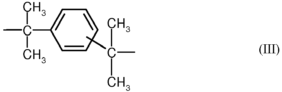
- B jeweils C1 bis C12-Alkyl, vorzugsweise Methyl, Halogen, vorzugsweise Chlor und/oder Brom
- x jeweils unabhängig voneinander 0, 1 oder 2,
- p 1 oder 0 sind, und
- R5 und R6 für jedes X1 individuell wählbar, unabhängig voneinander Wasserstoff oder C1 bis C6-Alkyl, vorzugsweise Wasserstoff, Methyl oder Ethyl,
- X1 Kohlenstoff und
- m eine ganze Zahl von 4 bis 7, bevorzugt 4 oder 5 bedeuten, mit der Maßgabe, dass an mindestens einem Atom X1, R5 und R6 gleichzeitig Alkyl sind.
- Für die Herstellung der Polycarbonate geeignete Diphenole sind beispielsweise Hydrochinon, Resorcin, Dihydroxydiphenyle, Bis-(hydroxyphenyl)-alkane, Bis(hydroxyphenyl)-cycloalkane, Bis-(hydroxyphenyl)-sulfide, Bis-(hydroxyphenyl)-ether, Bis-(hydroxyphenyl)-ketone, Bis-(hydroxyphenyl)-sulfone, Bis-(hydroxyphenyl)-sulfoxide, alpha-alpha'-Bis-(hydroxyphenyl)-diisopropylbenzole,Phtalimidine abgeleitet von Isatin- oder Phenolphthaleinderivaten sowie deren kernalkylierte und kernhalogenierte Verbindungen.
- Bevorzugte Diphenole sind 4,4'-Dihydroxydiphenyl, 2,2-Bis-(4-hydroxyphenyl)-propan, 2,4-Bis-(4-hydroxyphenyl)-2-methylbutan, 1,1-Bis-(4-hdydroxyphenyl)-p-diisopropylbenzol, 2,2-Bis-(3-methyl-4-hydroxyphenyl)-propan, 2,2-Bis-(3-chlor-4-hydroxyphenyl)-propan, Bis-(3,5-dimethyl-4-hydroxyphenyl)-methan, 2,2-Bis-(3,5-dimethyl-4-hydroxyphenyl)-propan, Bis-(3,5-dimethyl-4-hydroxyphenyl)-sulfon, 2,4-Bis-(3,5-dimethyl-4-hydroxyphenyl)-2-methylbutan, 1,1-Bis-(3,5-dimethyl-4-hydroxyphenyl)-p-diisopropylbenzol, 2,2-Bis-(3,5-dichlor-4-hydroxyphenyl)-propan, 2,2-Bis-(3,5-dibrom-4-hydroxyphenyl)-propan, 1,1-Bis-(4-hydroxyphenyl)-3,3,5-trimethylcyclohexan, und 2-Hydrocarbyl-3,3-Bis(4-Hydroxyaryl)phthalimidine sowie dem Reaktionsprodukt von N-Phenylisatin und Phenol.
- Besonders bevorzugte Diphenole sind 2,2-Bis-(4-hydroxyphenyl)-propan, 2,2-Bis-(3,5-dimethyl-4-hydroxyphenyl)-propan, 2,2-Bis-(3,5-dichlor-4-hydroxyphenyl)-propan, 2,2-Bis-(3,5-dibrom-4-hydroxyphenyl)-propan, 1,1-Bis-(4-hydroxyphenyl)-cyclohexan und 1,1-Bis-(4-hydroxyphenyl)-3,3,5-trimethylcyclohexan.
- Im Fall der Homopolycarbonate ist nur ein Diphenol eingesetzt, im Fall der Copolycarbonate sind mehrere Diphenole eingesetzt. Geeignete Kohlensäurederivate sind beispielsweise Phosgen oder Diphenylcarbonat.
- Geeignete Kettenabbrecher, die bei der Herstellung der Polycarbonate eingesetzt werden können, sind sowohl Monophenole als auch Monocarbonsäuren. Geeignete Monophenole sind Phenol selbst, Alkylphenole wie Kresole, p-tert.-Butylphenol, Cumylphenol, p-n-Octylphenol, p-iso-Octylphenol, p-n-Nonylphenol und p-iso-Nonylphenol, Halogenphenole wie p-Chlorphenol, 2,4-Dichlorphenol, p-Bromphenol und 2,4,6-Tribromphenol, 2,4,6-Trijodphenol, p-Jodphenol, sowie deren Mischungen. Bevorzugte Kettenabbrecher sind Phenol, Cumylphenol und/oder p-tert.-Butylphenol.
- Besonders bevorzugte Polycarbonate im Rahmen der vorliegenden Erfindung sind Homopolycarbonate auf Basis von Bisphenol A und Copolycarbonate auf Basis der Monomere ausgewählt aus mindestens einem der Gruppe aus Bisphenol A, 1,1-Bis-(4-hydroxyphenyl)- 3,3,5-trimethylcyclohexan, 2-Hydrocarbyl-3,3-Bis(4-Hydroxyaryl)phthalimidine und den Reaktionsprodukten aus N-Phenylisatin und Phenol. Die Polycarbonate können in bekannter Weise linear oder verzweigt sein. Der Anteil der Co-Monomere bezogen auf Bisphenol A beträgt im Allgemeinen bis zu 60 Gew. %, bevorzugt bis zu 50 Gew-%, besonders bevorzugt 3 bis 30 Gew-%. Mischungen von Homopolycarbonat und Copolycarbonaten können ebenfalls verwendet werden.
- Polycarbonate und Co-Polycarbonate enthaltend 2-Hydrocarbyl-3,3-Bis(4-Hydroxyaryl)phthalimidine als Monomere sind unter anderem bekannt aus
EP 1 582 549 A1 . Polycarbonate und Co-Polycarbonate enthaltend Bisphenolmonomere basierend auf Reaktionsprodukten aus N-Phenylisatin und Phenol sind beispielsweise inWO 2008/037364 A1 beschrieben. - Die thermoplastischen, aromatischen Polycarbonate haben mittlere Molekulargewichte (Gewichtsmittel Mw, gemessen durch GPC (Gelpermeationschromatographie mit Polycarbonatstandard) von 10.000 bis 80.000 g/mol, bevorzugt 14.000 bis 32.000 g/mol, besonders bevorzugt 18.000 bis 32.000 g/mol. Im Falle spritzgegossener Polycarbonat-Formteile beträgt das bevorzugte mittlere Molekulargewicht 20.000 bis 29.000 g/mol. Im Falle von extrudierten Polycarbonat-Formteilen beträgt das bevorzugte mittlere Molekulargewicht 25.000 bis 32.000 g/mol.
- Die Polycarbonate können ferner Füllstoffe enthalten. Als Füllstoffes sind Glaskugeln, Glashohlkugeln, Glasflakes, Ruße, Graphite, Kohlenstoffnanoröhrchen, Quarze, Talk, Glimmer, Silikate, Nitride, Wollastonit, sowie pyrogene oder gefällte Kieselsäuren, wobei die Kieselsäuren BET-Oberflächen von mindestens 50 m2/g (nach DIN 66131/2) aufweisen, geeignet.
- Bevorzugte faserförmige Füllstoffe sind metallische Fasern, Kohlenstofffasern, Kunststofffasern, Glasfasern oder gemahlene Glasfasern, besonders bevorzugt sind Glasfasern oder gemahlene Glasfasern. Bevorzugte Glasfasern sind auch solche, die in der Ausführungsform Endlosfaser (rovings), Langglasfasern und Schnittglasfasern verwendet werden, die aus M-, E-, A-, S-, R- oder C-Glas herstellt werden, wobei E-, A-, oder C-Glas weiter bevorzugt sind.
- Der Durchmesser der Fasern beträgt bevorzugt 5 bis 25 µm, weiter bevorzugt 6 bis 20 µm, besonders bevorzugt 7 bis 15 µm. Langglasfasern weisen bevorzugt eine Länge von 5 bis 50 mm, weiter bevorzugt von 5 bis 30 mm, noch weiter bevorzugt von 6 bis 15mm, und besonders bevorzugt von 7 bis 12 mm auf; sie werden beispielsweise in
WO-A 2006/040087 beschrieben. Die Schnittglasfasern weisen bevorzugt zu mindestens 70 Gew.% der Glasfasern eine Länge von mehr als 60 µm auf. - Weitere anorganischen Füllstoffe sind anorganische Partikel mit Korngestalt ausgewählt aus der Gruppe, die sphärische / kubische, tabular / diskusförmige und plattiger Geometrien umfasst. Insbesondere geeignet sind anorganische Füllstoffe mit sphärischer oder plattiger, bevorzugt in feinteiliger und/oder poröser Form mit großer äußerer und/oder innerer Oberfläche. Dabei handelt es sich bevorzugt um thermisch inerte anorganische Materialien insbesondere basierend auf Nitride wie Bornitrid, um Oxide oder Mischoxide wie Ceroxid, Alumimiumoxid, um Carbide wie Wolframcarbid, Siliciumcarbid oder Borcarbid gepulvertem Quarz wie Quarzmehl, amorphes SiO2, gemahlener Sand, Glaspartikel wie Glaspulver, insbesondere Glaskugeln, Silikate oder Alumosilikate, Graphit, insbesondere hochreiner synthetischer Graphit. Insbesondere bevorzugt sind dabei Quarz und Talk, am stärksten bevorzugt Quarz (sphärische Korngestalt). Diese Füllstoffe sind durch einen mittleren Durchmesser d50% von 0,1 bis 10 µm, vorzugsweise von 0.2 bis 8.0 µm, weiter bevorzugt von 0.5 bis 5 µm, gekennzeichnet.
- Silikate sind durch einen mittleren Durchmesser d50% von 2 bis 10 µm, vorzugsweise von 2.5 bis 8.0 µm, weiter bevorzugt von 3 bis 5 µm, und besonders bevorzugt von 3 µm, gekennzeichnet, wobei ein oberer Durchmesser d95% von entsprechend 6 bis 34 µm, weiter bevorzugt von 6.5 bis 25.0 µm, noch weiter bevorzugt von 7 bis 15 µm, und besonders bevorzugt von 10 µm bevorzugt ist. Bevorzugt weisen die Silikate eine spezifische BET-Oberfläche, bestimmt durch Stickstoffadsorption gemäß ISO 9277, von 0.4 bis 8.0 m2/g, weiter bevorzugt von 2 bis 6 m2/g, und besonders bevorzugt von 4.4 bis 5.0 m2/g auf.
- Weiter bevorzugte Silikate weisen nur maximal 3 Gew.-% Nebenbestandteile auf, wobei vorzugsweise der Gehalt an
- Al2O3 < 2.0 Gew.%,
- Fe2O3 < 0.05 Gew.%,
- (CaO + MgO) <0.1 Gew.%,
- (Na2O + K2O) < 0.1 Gew.%) ist, jeweils bezogen auf das Gesamtgewicht des Silikats.
- Eine weitere vorteilhafte Ausführungsform verwendet Wollastonit oder Talk in Form von feinvermahlenen Typen mit einem mittleren Partikeldurchmesser d50 von <10 µm, bevorzugt <5 µm, besonders bevorzugt <2 µm, ganz besonders bevorzugt <1,5 µm. Die Korngrößenverteilung wird durch Windsichten bestimmt.
- Die Silikate können eine Beschichtung mit silicium-organischen Verbindungen haben, wobei bevorzugt Epoxysilan-, Methylsiloxan-, und Methacrylsilan-Schlichten zum Einsatz kommen. Besonders bevorzugt ist eine Epoxysilanschlichte.
- Die Füllstoffe können in einer Menge bis zu 40 Gew.% bezogen auf die Menge an Polycarbonat zugesetzt werden. Bevorzugt sind 2,0 bis 40,0 Gew.-%, bevorzugt 3,0 bis 30,0 Gew.-%, weiter bevorzugt 5,0 bis 20,0 Gew.-%, und besonders bevorzugt 7,0 bis 14,0 Gew.-%.
- Als Blendpartner für Polycarbonate sind Pfropfpolymerisate von Vinylmonomeren auf Pfropfgrundlagen wie Dienkautuschke oder Acrylatkautschuke geeignet. Pfropfpolymerisate B sind bevorzugt solche aus
- B.1 5 bis 95, vorzugsweise 30 bis 90 Gew.-%, wenigstens eines Vinylmonomeren auf
- B.2 95 bis 5, vorzugsweise 70 bis 10 Gew.-% einer oder mehrerer Pfropfgrundlagen mit Glasübergangstemperaturen < 10°C, vorzugsweise < 0°C, besonders bevorzugt < -20°C.
- Die Pfropfgrundlage B.2 hat im Allgemeinen eine mittlere Teilchengröße (d50-Wert) von 0,05 bis 10 µm, vorzugsweise 0,1 bis 5 µm, besonders bevorzugt 0,2 bis 1 µm.
- Monomere B.1 sind vorzugsweise Gemische aus
- B.1.1 50 bis 99 Gew.-Teilen Vinylaromaten und/oder kernsubstituierten Vinylaromaten (wie Styrol, α-Methylstyrol, p-Methylstyrol, p-Chlorstyrol) und/oder Methacrylsäure-(C1-C8)-Alkylester, wie Methylmethacrylat, Ethylmethacrylat), und
- B.1.2 1 bis 50 Gew.-Teilen Vinylcyanide (ungesättigte Nitrile wie Acrylnitril und Methacrylnitril) und/oder (Meth)Acrylsäure-(C1-C8)-Alkylester, wie Methylmethacrylat, n-Butylacrylat, t-Butylacrylat, und/oder Derivate (wie Anhydride und Imide) ungesättigter Carbonsäuren, beispielsweise Maleinsäureanhydrid und N-Phenyl-Maleinimid.
- Bevorzugte Monomere B.1.1 sind ausgewählt aus mindestens einem der Monomere Styrol, α-Methylstyrol und Methylmethacrylat, bevorzugte Monomere B.1.2 sind ausgewählt aus mindestens einem der Monomere Acrylnitril, Maleinsäureanhydrid und Methylmethacrylat. Besonders bevorzugte Monomere sind B.1.1 Styrol und B.1.2 Acrylnitril.
- Für die Pfropfpolymerisate B geeignete Pfropfgrundlagen B.2 sind beispielsweise Dienkautschuke, EP(D)M-Kautschuke, also solche auf Basis Ethylen/Propylen und gegebenenfalls Dien, Acrylat-, Polyurethan-, Silikon-, Chloropren und Ethylen/Vinylacetat-Kautschuke.
- Bevorzugte Pfropfgrundlagen B.2 sind Dienkautschuke, beispielsweise auf Basis Butadien und Isopren, oder Gemische von Dienkautschuken oder Copolymerisate von Dienkautschuken oder deren Gemischen mit weiteren copolymerisierbaren Monomeren (z.B. gemäß B.1.1 und B.1.2), mit der Maßgabe, dass die Glasübergangstemperatur der Komponente B.2 unterhalb < 10°C, vorzugsweise < 0°C, besonders bevorzugt < -10°C liegt. Besonders bevorzugt ist reiner Polybutadienkautschuk.
- Besonders bevorzugte Polymerisate B sind beispielsweise ABS-Polymerisate (Emulsions-, Masse- und Suspensions-ABS), wie sie z.B. in der
DE-OS 2 035 390 (=US-PS 3 644 574 ) oder in derDE-OS 2 248 242 (=GB-PS 1 409 275 - Die Pfropfcopolymerisate B werden durch radikalische Polymerisation, z.B. durch Emulsions-, Suspensions-, Lösungs- oder Massepolymerisation, vorzugsweise durch Emulsions- oder Massepolymerisation hergestellt.
- Da bei der Pfropfreaktion die Pfropfmonomeren bekanntlich nicht unbedingt vollständig auf die Pfropfgrundlage aufgepfropft werden, werden erfindungsgemäß unter Pfropfpolymerisaten B auch solche Produkte verstanden, die durch (Co)Polymerisation der Pfropfmonomere in Gegenwart der Pfropfgrundlage gewonnen werden und bei der Aufarbeitung mit anfallen.
- Die Polymer-Zusammensetzungen können optional noch weitere übliche Polymeradditive enthalten, wie z.B. die in
EP-A 0 839 623 ,WO-A 96/15102 EP-A 0 500 496 oder "Plastics Additives Handbook", Hans Zweifel, 5th Edition 2000, Hanser Verlag, München) beschriebenen Antioxidantien, Thermostabilisatoren, Entformungsmittel, optischen Aufheller, UV Absorber und Lichtstreumittel in den für die jeweiligen Thermoplasten üblichen Mengen. - Als UV-Stabilisatoren sind Benzotriazole, Triazine, Benzophenone und/oder arylierte Cyanoacrylate geeignet. Besonders geeignete UV-Absorber sind Hydroxy-Benzotriazole, wie 2-(3',5'-Bis-(1,1-dimethylbenzyl)-2'-hydroxy-phenyl)-benzotriazol (Tinuvin® 234, Ciba Spezialitätenchemie, Basel), 2-(2'-Hydroxy-5'-(tert.-octyl)-phenyl)-benzotriazol (Tinuvin® 329, Ciba Spezialitätenchemie, Basel), 2-(2'-Hydroxy-3'-(2-butyl)-5'-(tert.butyl)-phenyl)-benzotriazol (Tinuvin® 350, Ciba Spezialitätenchemie, Basel), Bis-(3-(2H-benztriazolyl)-2-hydroxy-5-tert.-octyl)methan, (Tinuvin® 360, Ciba Spezialitätenchemie, Basel), (2-(4,6-Diphenyl-1,3,5-triazin-2-yl)-5-(hexyloxy)-phenol (Tinuvin® 1577, Ciba Spezialitätenchemie, Basel), sowie der Benzophenone 2,4-Dihydroxy-benzophenon (Chimasorb® 22, Ciba Spezialitätenchemie, Basel) und 2-Hydroxy-4-(octyloxy)-benzophenon (Chimassorb® 81, Ciba, Basel), 2-Propenoic acid, 2-Cyano-3,3-diphenyl-, 2,2-Bis[[(2-cyano-1-oxo-3,3-diphenyl-2-propenyl)oxy]-methyl]-1,3-propanediylester (9CI) (Uvinul® 3030, BASF AG Ludwigshafen), 2-[2-Hydroxy-4-(2-ethylhexyl)oxy]phenyl-4,6-di(4-phenyl)phenyl-1,3,5-triazine (CGX UVA 006, Ciba Spezialitätenchemie, Basel) oder Tetra-ethyl-2,2'-(1,4-phenylene-dimethylidene)-bismalonate (Hostavin® B-Cap, Clariant AG).
- Die Polymer-Zusammensetzung kann UV-Absorber üblicherweise in einer Menge von 0 bis 5 Gew.%, bevorzugt 0,1 bis 2,5 Gew.% bezogen auf die Gesamtzusammensetzung enthalten.
- Die Herstellung der Polymer-Zusammensetzungen erfolgt mit gängigen Einarbeitungsverfahren durch Zusammenführung, Vermischen und Homogenisieren der einzelnen Bestandteile, wobei insbesondere die Homogenisierung bevorzugt in der Schmelze unter Einwirkung von Scherkräften stattfindet. Gegebenenfalls erfolgt das Zusammenführen und Vermischen vor der Schmelzehomogenisierung unter Verwendung von Pulvervormischungen.
- Das Substratmaterial kann als Folie oder Platte vorliegen. Die Folie kann verformt und mit einem weiteren Thermoplasten aus den oben genannten Thermoplasten hinterspritzt werden (Film Insert Molding (FIM)). Platten können thermogeformt oder mittels Drape-Forming bearbeitet bzw. kalt eingebogen werden. Auch ist eine Formgebung über Spritzguss-Prozesse möglich. Diese Prozesse sind dem Fachmann bekannt.
- Die Dicke der Substratschicht muss hierbei so beschaffen sein, dass im Bauteil eine hinreichende Steifigkeit gewährleistet ist.
- Im Falle einer Folie kann die Substratschicht A durch Hinterspritzen verstärkt werden, um eine ausreichende Steifigkeit zu gewährleisten.
- Die Gesamtdicke der Schicht A, d.h. einschließlich einer möglichen Hinterspritzung, beträgt im allgemeinen 1µm - 10 mm. Besonders bevorzugt beträgt die Dicke der Schicht A) 1 mm - 10 mm, 1 mm - 5 mm, 2 mm - 4 mm. Insbesondere beziehen sich die Dickenangaben auf die Gesamtsubstratdicke bei Verwendung von Polycarbonat als Substratmaterial einschließlich einer möglichen Hinterspritzung.
- Bei PET beträgt die Schichtdicke vorzugsweise 10µm - 100 µm (PET), die Dicker einer PC-Folie beträgt bevorzugt 100 µm - 1mm (PC-Folie), wobei durch Hinterspritzung diese Thermoplasten verstärkt werden können.
- Bei metallischen Substraten beträgt die Schichtdicke im Allgemeinen 300 µm - 750 µm. Bei Glassubstraten beträgt die Schichtdicke im Allgemeinen 750 µm - 3 mm, bevorzugt 800 µm - 2 mm.
- Schicht B ist ausgewählt aus den oben genannten Metallen. Schicht B ist bevorzugt frei von Kupfer oder Kupfer haltigen Verbindungen bzw. Kupfer haltigen Legierungen.
- Die Dicke der Schicht B beträgt im allgemeinen 40 nm - 250 nm, bevorzugt 55 nm - 200 nm und insbesondere 80 nm - 130 nm.
- Die besonders bevorzugte Schichtdicke bei Verwendung von Titan liegt im Bereich von 105 nm - 120 nm.
- Die Dicke der Schicht C beträgt im allgemeinen 80 nm - 250 nm, bevorzugt 90 nm - 160 nm und besonders bevorzugt 100 nm - 130 nm.
- Im Falle von Silber wird hochreines Silber eingesetzt. Kommerziell verfügbare Produkte sind bei Heraeus Precious Metals (z.B: Target Ag Reinheit 3N7) oder Umicore erhältlich.
- Die Dicke der Schicht D beträgt im allgemeinen 80 nm - 250 nm, bevorzugt 90 nm - 160 nm, besonders bevorzugt 90 nm - 130 nm und ganz besonders bevorzugt 90 nm - 110 nm.
- Die Dicke der Schicht E beträgt im allgemeinen 1 nm - 200 nm, bevorzugt 10 nm - 150 nm, besonders bevorzugt 20 nm- 100 nm und ganz besonders bevorzugt 30 nm - 50 nm.
- Die Schichten B und C werden jeweils durch Aufdampfen oder durch Sputtern aufgebracht.
- Die Schicht D wird reaktiv aufgedampft oder reaktiv gesputtert mit Sauerstoff als Reaktivgas. Diese Verfahren sind allgemein bekannt und zum Beispiel beschrieben in Vakuumbeschichtung, Band 1-5, Hrsg. Hartmut Frey, VDI Verlag, 1995.
- Der Auftrag von Metallen auf das Polymer kann über verschiedene Methoden wie z.B. durch Aufdampfen oder Sputtern geschehen. Die Verfahren sind näher beschrieben z.B. in "Vakuumbeschichtung Bd.1 bis 5", H. Frey, VDI-Verlag Düsseldorf 1995 oder "Oberflächen- und Dünnschicht-Technologie" Teil 1, R.A. Haefer, Springer Verlag 1987.
- Um eine bessere Metallhaftung zu erreichen und um die Substratoberfläche zu reinigen, werden die Substrate normalerweise einer Plasmavorbehandlung unterzogen. Eine Plasmavorbehandlung kann u. U. die Oberflächeneigenschaften von Polymeren verändern. Diese Methoden sind z.B. bei Friedrich et al. in Metallized plastics 5 & 6: Fundamental and applied aspects und H. Grünwald et al. in Surface and Coatings Technology 111 (1999) 287-296 beschrieben.
- Die Schicht E wird in einem PECVD (plasma enhanced chemical vapour deposition) oder Plasmapolymerisationsprozess aufgebracht. Hierbei werden niedrigsiedende Precursoren haupsächlich auf Siloxan-Basis in ein Plasma verdampft und dadurch aktiviert, so dass sie einen Film bilden können. Das Verfahren ist unter anderem beschrieben in Surface and Coatings Technology 111 (1999), 287-296.
- Anorganische Deckschichten im Sinne der vorliegenden Erfindung sind Lacke, die nach dem Sol-Gel-Prozess hergestellt werden und unten beschrieben sind. Der Sol-Gel-Prozess ist ein Verfahren zur Synthese nichtmetallischer anorganischer oder hybridpolymerer Materialien aus kolloidalen Dispersionen, den sogenannten Solen.
- Anorganische Deckschichten, die nach dem Sol-Gel Prozess hergestellt wurden, sind kommerziell unter der Bezeichnung Silfort PHC587, Silfort PHC587B, Silfort PHC587C, Silfort SHC5020, Silfort AS4000 sowie Silfort AS4700 (Momentive Performance Materials), CrystalCoat 6000 (SDC Technologies), PERMA-NEW 6000 (oder PERMA-NEW 6000B) CLEAR HARD COATING SOLUTION (California Hardcoating Co.) sowie KASI flex und KASI sunflex (KRD) verfügbar.
- Die Deckschicht ist dadurch gekennzeichnet, dass sie keine UV Absorber enthält.
- Die Sol-Gel-Beschichtungslösungen werden durch Hydrolyse wässriger Dispersionen von kolloidem Siliziumdioxid und einem Organoalkoxysilan und/oder einem Alkoxysilan oder Mischungen aus Organoalkoxysilanen der allgemeinen Formel RSi(OR')3 und/oder Alkoxysilanen der allgemeinen Formeln Si(OR')4 herstellt werden, wobei in den Organoalkoxysilan(en) der allgemeinen Formel RSi(OR')3 R für einen monovalenten C1 bis C6 - Alkyl-Rest oder für einen ganz oder teilweise fluorierten C1 - C6 - Alkylrest, für eine Vinyl- oder eine Allyl-Einheit, einen Arylrest oder für ein C1 - C6 Alkoxygruppe steht. Besonders bevorzugt ist R eine C1 bis C4-Alkylgruppe, eine Methyl-, Ethyl-, n-Propyl-, iso-Propyl-, tert.-Butyl-, sek.-Butyl- oder n-Butylgruppe, eine Vinyl-, Allyl-, Phenyl- oder substituierte Phenyleinheit. Die - OR' sind unabhängig voneinander ausgewählt aus der Gruppe enthaltend C1 bis C6 - Alkoxygruppen, eine Hydroxygruppe, eine Formyleinheit und eine Acetyl-Einheit. Sol-Gel-Polysiloxanlacke fallen teilweise auch unter die Definition eines Hybridlackes.
- Das kolloide Siliziumdioxid ist beispielsweise als z.B. Levasil 200 A (HC Starck), Nalco 1034A (Nalco Chemical Co), Ludox AS-40 oder Ludox LS (GRACE Davison) erhältlich. Als Organoalkoxysilane seien beispielhaft folgende Verbindungen genannt: 3,3,3-Trifluoropropytrimethoxysilan, Methyltrimethoxysilan, Methyltrihydroxysilan, Methyltriethoxysilan, Ethyltrimethoxysilan, Methyltriacetoxysilan, Ethyltriethoxysilan, Phenyltrialkoxysilan (z.B. Phenyltriethoxysilan und Phenyltrimethoxysilan) und Mischungen daraus. Als Alkoxysilane seien beispielhaft folgende Verbindungen genannt: Tetramethoxysilan und Teraethoxysilan und Mischungen daraus.
- Als Katalysatoren können beispielsweise organische und/oder anorganische Säuren oder Basen verwendet werden.
- In einer Ausführungsform können die kolloiden Siliziumdioxidpartikel auch durch Vorkondensation ausgehend von Alkoxysilanen in situ gebildet werden (siehe hierzu "The Chemistry of Silica", Ralph K. Iler, John Wiley & Sons, (1979), p. 312-461).
- Die Hydrolyse der Sol-Gel-Lösung wird durch Zugabe von Lösungsmitteln, bevorzugt alkoholischen Lösungsmitteln wie z.B. Isopropanol, n-Butanol, Isobutanol oder Mischungen daraus, abgebrochen bzw. stark verlangsamt. Anschließend folgt ein Alterungsschritt von wenigen Stunden oder mehreren Tagen/Wochen. Des Weiteren können Additive und/oder Stabilisatoren wie beispielsweise Verlaufsmittel, Oberflächenadditive, Verdickungsmittel, Pigmente, Farbstoffe, Härtungskatalysatoren, IR-Absorber, UV-Absorber und/oder Haftvermittler zugesetzt werden. Auch die Verwendung von Hexamethyldisilazan oder vergleichbaren Verbindungen, die zu einer reduzierten Rissanfälligkeit der Beschichtungen führen können, ist möglich (vgl. auch
WO 2008/109072 A ). - Hybridlacke im Sinne der vorliegenden Erfindung basieren auf der Verwendung von Hybridpolymeren als Bindemittel. Hybridpolymere (Hybride: lat. "von zweierlei Herkunft") sind polymer basierte Werkstoffe, die Struktureinheiten verschiedener Materialklassen auf molekularer Ebene in sich vereinen. Durch ihren Aufbau können Hybridpolymere völlig neuartige Eigenschaftskombinationen aufweisen. Im Unterschied zu Verbundwerkstoffen (definierte Phasengrenzen, schwache Wechselwirkungen zwischen den Phasen) und Nanokompositen (Verwendung nanoskaliger Füllstoffe) sind die Struktureinheiten von Hybridpolymeren auf molekularer Ebene miteinander verknüpft. Dies gelingt durch chemische Verfahren wie z. B. den Sol-Gel-Prozess, mit dem anorganische Netzwerke aufgebaut werden können. Durch den Einsatz von organisch reaktiven Precursoren z. B. organisch modifizierten Metall-Alkoxiden können zusätzlich organische Oligomer/Polymerstrukturen erzeugt werden. Oberflächenmodifizierte Nanopartikel enthaltende Acrylatlacke, die nach der Härtung ein organisch/anorganisches Netzwerk bilden, werden ebenfalls als Hybridlack definiert. Es gibt thermisch härtbare und UV-härtbare Hybridlacke.
- Als Schicht F werden thermisch-härtbare Sol-Gel-Lacke ohne zusätzlichen UV-Absorber, wie beispielsweise von der Fa. Momentive Performance Materials unter der Produktbezeichnung SHC5020 erhältlich, eingesetzt. Sol-Gel-Polysiloxanlacke werden in Schichtdicken von 1 bis 20 µm, bevorzugt 2 bis 15 µm, besonders bevorzugt 4 bis 12 µm eingesetzt.
- Für den Fall, dass in dem erfindungsmäßen Schichtaufbau die Schicht D Aluminiumoxid enthält, wird die Deckschicht F bevorzugt durch ein anorganisches Lacksystem gebildet.
- Optional kann ein Primer zwischen der anorganischen Deckschicht F und der Schicht E Verwendung finden. Der Primer hat die Aufgabe die Haftvermittlung zwischen diesen beiden Schichtsystemen zu gewährleisten. Bevorzugte Primer basieren auf Poly(meth)acrylaten, bevorzugt Polymethylmethacrylat (PMMA), und sind kommerziell erhältlich unter der Produktbezeichnung SHP401, SHP470 oder SHP470FT von der Fa. Momentive Performance Materials. Üblicherweise werden diese in Schichtdicken zwischen 50nm und 4µm, bevorzugt zwischen 100nm und 1,3µm (SHP401) sowie 1,2µm bis 4µm (SHP470 bzw. SHP470FT) verwendet.
- Die Applikation der anorganischen Deckschichten sowie Primer erfolgt bevorzugt durch Fluten, Gießen, Rakeln, Sprühen, Walzen oder Tauchen, insbesondere durch Fluten, Gießen oder Sprühen.
- Bevorzugt liegen die Härtungstemperaturen der anorganischen Deckschicht bei kleiner gleich 100°C falls in dem Gesamtaufbau der vorliegenden Erfindung die Schicht D verwendet wird.
- In einer alternativen Ausführungsform der vorliegenden Erfindung ist die Schicht D frei von Aluminiumoxid und die Härtung der Schicht F erfolgt bei Temperaturen größer 100°C.
- In einer weiteren bevorzugten Ausführungsform werden die anorganischen Deckschichten der Schicht F durch chemische Gasphasenabscheidung, einem PECVD (plasma enhanced chemical vapour deposition) oder Plasmapolymerisationsprozess aufgebracht. Hierbei werden niedrigsiedende Precursoren haupsächlich auf Siloxan-Basis in ein Plasma verdampft und dadurch aktiviert, so dass sie einen Film bilden können.
- Als Precursoren werden beispielsweise und bevorzugt Hexamethyldisiloxan (HMDSO), Octamethylcyclotetrasiloxan (OMCTS), Octamethyltrissiloxan (OMTS), Tetraethylorthosilan (TEOS), und Tetrametyldisiloxan (TMDSO), Decamethylcyclopentasiloxan (DMDMS), Hexamethylcyclotrisiloxan (HMCTS), Trimethoxymethylsilan (TMOMS), Tetramethylcyclotetrasiloxan (TMCTS); besonders bevorzugt wird HMDSO eingesetzt.
- Bevorzugte Schichtdicken sind größer gleich 1µm. Mit Hilfe des Sauerstoffs zum Precursorverhältnis kann die mechanische Stabilität der resultierenden Schichten variiert werden. Das bevorzugte Verhältnis hängt vom verwendeten Precursor ab. Für HMDSO liegt das bevorzugte Verhältnis von Sauerstoff zu HMDSO bei 50 bis 1, besonders bevorzugt bei 30 bis 1 und insbesondere bevorzugt bei 20 bis 5.
- Das Verfahren ist unter anderem beschrieben in Surface and Coatings Technology 111 (1999), 287-296.
- Es wurden Spritzguss-Rechteckplatten mit den Maßen 150 x 105 x 3,2 mm mit Seitenanguss angefertigt. Die Massetemperatur betrug 300 - 330°C und die Werkzeugtemperatur 100°C. Das jeweilige Granulat wurde vor Verarbeitung für 5 Stunden im Vakuumtrockenschrank bei 120°C getrocknet.
- PC-1: Makrolon® 2407, Bayer MaterialScience AG, Leverkusen, Deutschland, mit einer Schmelze-Volumenfließrate (MVR) von 19 cm3/10min, gemessen nach ISO 1133 bei 300 und 1,2 kg.
- PC-2: Makrolon® GP U099, Bayer MaterialScience AG, Leverkusen, Deutschland, mit einer Schmelze-Volumenfließrate (MVR) von 10 cm3/10min, gemessen nach ISO 1133 bei 300 und 1,2 kg.
- Die PC-Platte (PC-1) wurde beschichtet gemäß nachfolgender Beschreibung. Folgender Schichtaufbau wurde realisiert:
- 3,2 mm Substrat\\110nm Ti\\120nm Ag\\100nm AlOx\\40nm HMDSO
- Herstellungsverfahren:
- 1. Die PC-Platte wurde in die Vakuumkammer eingeschleust und bis auf p< 2·10-5 mbar evakuiert.
- 2. Plasmavorbehandlung: Die PC-Platte wurde 1 min bei 500W und 0,1 mbar Ar im Mittelfrequenz-Plasma (40kHz) vorbehandelt.
- 3. Schicht B: Die Titan-Schicht wurde mittels DC sputtern abgeschieden. Als Beschichtungsquelle wurde ein rundes Planarmagnetron ION'X-8"HV von Thin Film Consulting mit einem Durchmesser von 200mm verwendet, die mit einem Generator "Pinnacle™ Plus+ 5kW" von Advanced Energy betrieben wurde. Zuerst wurde das Target (hier: Titan) bei geschlossener Blende für 1min freigesputtert und dann bei offener Blende innerhalb von 3min 40s mit 2000W und einem Druck von p= 5·10-3 mbar die Titanschicht auf der PC-Platte abgeschieden.
- 4. Schicht C: Die Silber-Schicht wurde mittels DC sputtern abgeschieden. Als Beschichtungsquelle wurde ein rundes Planarmagnetron ION'X-8"HV von Thin Film Consulting mit einem Durchmesser von 200mm verwendet, die mit einem Generator "Pinnacle™ Plus+ 5kW" von Advanced Energy betrieben wurde. Zuerst wurde das Target (hier: Silber) bei geschlossener Blende für 1min freigesputtert und dann bei offener Blende innerhalb von 51s mit 2000W und einem Druck von p= 5·10-3 mbar die Silberschicht auf der Titanschicht abgeschieden.
- Danach wurde die beschichtete PC-Platte aus der Beschichtungsanlage entnommen und die Beschichtungsanlage für die letzten Schichten vorbereitet.
- 5. Die beschichtete PC-Platte wurde wieder in die Vakuumkammer eingeschleust und bis auf p< 2·10-5 mbar evakuiert.
- 6. Plasmavorbehandlung: die beschichtete PC-Platte wurde 1 min bei 500W und 0,1 mbar Ar im Mittelfrequenz-Plasma (40kHz) vorbehandelt.
- 7. Schicht D: Die AlOx-Schicht wurde mittels reaktiv, gepulstem DC sputtern mit einer Pulsfrequenz von 150 kHz abgeschieden. Als Beschichtungsquelle wurde ein rundes Planarmagnetron ION'X-8"HV von Thin Film Consulting mit einem Durchmesser von 200mm verwendet, die mit einem Generator Advanced Energy "Pinnacle™ Plus+ 5kW" betrieben wurde. Zuerst wurde das Target (hier: Aluminium) bei geschlossener Blende für 1min freigesputtert und dann bei offener Blende innerhalb von 4min bei 340V im spannungsgeregeltem Mode und einem Gesamtdruck von p= 5·10-3 mbar die AlOx-Schicht auf der Silberschicht abgeschieden. Das O2/Ar-Verhältnis wurde auf 8% eingestellt.
- 8. Schicht E: Mittels Plasmapolymerisation wurde HMDSO (Hexamethyldisiloxan) auf die AlOx-Schicht als weitere Schutzschicht aufgebracht. Die Schicht wurde bei einem Anfangsdruck von p=0.038 mbar und Fluss von 90sscm HMDSO und 1500W Mittelfrequenzleistung (40kHz) während 35s aufgebracht. Als Quelle wurde eine Parallelreaktoreinheit verwendet mit einem Plattenabstand von ca. 200mm, wobei sich die Platte in der Mitte befand. Die Quelle wurde mit einem Advanced Energy PEII (5kW) inkl. Hochspannungstrafo LMII betrieben.
- Die Platte wurde während allen Beschichtungsschritten über die Beschichtungsquellen mit ca. 20rpm rotiert, um die Homogenität der Beschichtung zu erhöhen.
- Die PC-Platte (PC-1) wurde beschichtet gemäß nachfolgender Beschreibung. Folgender Schichtaufbau wurde realisiert:
- 3,2 mm Substrat\\110nm Ti\\120nm Ag\\40nm HMDSO
- Herstellungsverfahren:
- 1. Die PC-Platte wurde in die Vakuumkammer eingeschleust und bis auf p< 2·10-5 mbar evakuiert.
- 2. Plasmavorbehandlung: Die PC-Platte wurde 1 min bei 500W und 0,1 mbar Ar im Mittelfrequenz-Plasma (40kHz) vorbehandelt.
- 3. Schicht B: Die Titan-Schicht wurde mittels DC sputtern abgeschieden. Als Beschichtungsquelle wurde ein rundes Planarmagnetron ION'X-8"HV von Thin Film Consulting mit einem Durchmesser von 200mm verwendet, die mit einem Generator "Pinnacle™ Plus+ 5kW" von Advanced Energy betrieben wurde. Zuerst wurde das Target (hier: Titan) bei geschlossener Blende für 1min freigesputtert und dann bei offener Blende innerhalb von 3min 40s mit 2000W und einem Druck von p= 5·10-3 mbar die Titanschicht auf der PC-Platte abgeschieden.
- 4. Schicht C: Die Silber-Schicht wurde mittels DC sputtern abgeschieden. Als Beschichtungsquelle wurde ein rundes Planarmagnetron ION'X-8"HV von Thin Film Consulting mit einem Durchmesser von 200mm verwendet, die mit einem Generator "Pinnacle™ Plus+ 5kW" von Advanced Energy betrieben wurde. Zuerst wurde das Target (hier: Silber) bei geschlossener Blende für 1min freigesputtert und dann bei offener Blende innerhalb von 51s mit 2000W und einem Druck von p= 5·10-3 mbar die Silberschicht auf der Titanschicht abgeschieden.
- Danach wurde die beschichtete PC-Platte aus der Beschichtungsanlage entnommen und die Beschichtungsanlage für die letzten Schichten vorbereitet.
- 5. Die beschichtete PC-Platte wurde wieder in die Vakuumkammer eingeschleust und bis auf p< 2·10-5 mbar evakuiert.
- 6. Plasmavorbehandlung: die beschichtete PC-Platte wurde 1 min bei 500W und 0,1 mbar Ar im Mittelfrequenz-Plasma (40kHz) vorbehandelt.
- 7. Schicht E: Mittels Plasmapolymerisation wurde HMDSO (Hexamethyldisiloxan) auf die Silber-Schicht als weitere Schicht aufgebracht. Die Schicht wurde bei einem Anfangsdruck von p=0.038 mbar und Fluss von 90sscm HMDSO und 1500W Mittelfrequenzleistung (40kHz) während 35s aufgebracht. Als Quelle wurde eine Parallelreaktoreinheit verwendet mit einem Plattenabstand von ca. 200mm, wobei sich die Platte in der Mitte befand. Die Quelle wurde mit einem Advanced Energy PEII (5kW) inkl. Hochspannungstrafo LMII betrieben.
- 8. Plasmavorbehandlung: die beschichtete PC-Platte wurde 1 min bei 500W und 0,1 mbar O2 im Mittelfrequenz-Plasma (40kHz) vorbehandelt.
- Die Platte wurde während allen Beschichtungsschritten über die Beschichtungsquellen mit ca. 20rpm rotiert, um die Homogenität der Beschichtung zu erhöhen.
- Zur Einstellung der Schichtdicken erfolgte zunächst eine Kalibrierung der Prozessparameter. Hierzu wurden unterschiedliche Schichtdicken bei definierten Prozessparametern auf einen Objektträger abgeschieden, der zur Erzeugung einer Stufe in der Mitte mit einem Klebestreifen versehen wurde. Nach Abscheidung der jeweiligen Schicht wurde der Klebestreifen entfernt und die Höhe der entstandenen Stufe mit einem Stufenabtaster KLA Tencor Alpha-Step 500 Surface Profiler von Tencor Instruments bestimmt.
- Hierdurch werden Prozessparameter ermittelt, die für die Herstellung der gewünschten Zielschichtdicke eingestellt werden müssen.
- Am Fertigteil lässt sich die Schichtdicke mittels TOF-SIMS (Time of Flight - Secondary Ion Mass Spectrometry) oder mit XPS (X-ray Photospectroscopy) in Kombination mit TEM (Transmission Electron Microscopy) bestimmen.
- In den nachfolgenden Beispielen wurden nachfolgende kommerziell verfügbare Deckschichtsysteme der Firma Momentive Performance Materials verwendet.
- SHP401: PMMA-Lösung in organischen Lösungsmitteln
- AS4000: thermisch-härtbarer anorganischer Decklack enthaltend UV-Absorber
- SHC5020: thermisch-härtbarer anorganischer Decklack ohne UV-Absorber
- UVHC3000: strahlungs-härtbarer organischer Decklack enthaltend UV-Absorber
- UVHC7800: strahlungs-härtbarer organischer Decklack ohne UV-Absorber
- Die Applikation des Primers SHP401 auf die Schicht E der Schichtfolge aus Beispiel 1 erfolgte bei 21°C und 34% relativer Feuchte durch Fluten. Während einer nachfolgenden Ablüftzeit von 30 Minuten bei zuvor genanntem Klima konnten restliche in der Lackschicht enthaltene Lösungsmittel verdunsten.
- Anschließend erfolgte die Applikation des Beschichtungsmittels SHC5020 auf die Primer-Schicht ebenfalls bei 21°C und 34% relativer Feuchte durch Fluten. Während einer nachfolgenden Ablüftzeit von 30 Minuten bei zuvor genanntem Klima konnten restliche in der Lackschicht enthaltene Lösungsmittel verdunsten. Abschließend wurde das Schichtsystem bestehend aus SHP401 und SHC5020 bei 130°C für 30 Minuten im Umluft-Trockenschrank gehärtet.
- Die Applikation des Beschichtungsmittels SHC5020 auf die Schicht E der Schichtfolge aus Beispiel 2 erfolgte bei 21°C und 34% relativer Feuchte durch Fluten. Während einer nachfolgenden Ablüftzeit von 30 Minuten bei zuvor genanntem Klima konnten restliche in der Lackschicht enthaltene Lösungsmittel verdunsten.
- Abschließend wurde das Schichtsystem bestehend aus SHC5020 bei 130°C für 30 Minuten im Umluft-Trockenschrank gehärtet.
- Es erfolgte die visuelle Überprüfung der Schichtfolgen aus den Beispielen 3a und 3b nach deren Herstellung.
Beispiel Ergebnis der visuellen Überprüfung 3a keine Auffälligkeiten; die Oberfläche ist intakt 3b keine Auffälligkeiten; die Oberfläche ist intakt - Test- und Auswertemethoden:
Prüfung Bedingungen Zeit (h) Beurteilung Klimawechsel-Test (DIN EN 62108 10.6 & 10.8) 100 Zyklen von -40°C bis 110°C (14 Zyklen pro Tag) gefolgt von 20 Zyklen Feuchte-Frost-Test (20h bei 85°C/85% relative Feuchte gefolgt von 4h Abkühlung auf -40°C und danach wieder aufheizen auf 85°C/85% relative Feuchte) Ca. 650h Bestimmung von RI Xenon-Test 0,75W/m2/nm bei 340nm, Boro-Boro Filter, Schwarztafeltemperatur 70°C, 50% relative Feuchte, ohne Beregnung 500h Bestimmung von RI Damp Heat Test (DIN EN 62108 10.7) 85°C, 85% relative Feuchte 2000h Bestimmung von RI Dry Heat Test Im Umlufttrockenschrank bei 125°C 1000h Bestimmung von RI - Bestimmung von RI (Reflexions-Index):
- 1. Bestimmung von totalem (Rtotal) und diffusem (Rdiffus) Reflexionsgrad mittels Photospektrometer Perkin Elmer Lambda 900, kalibriert auf Spektralon-Standard im Bereich von λ= 200-1100nm
- 2. Berechnung der direkten Reflexion: Rdirekt= Rtotal - Rdiffus
- 3. Berechnung von

- 4. Wobei RI = min (RIi) mit i = 1,2.
- EQEi(λ) (External Quantum Efficiency): z.B. Spectrolab C1MJ
- SP(λ) : Sonnenspektrum nach ASTM G173-03
- Direkter Reflexionsgrad und RI - Ausgangswerte:
Rdirekt RI 400nm 500nm 700nm 900nm Bsp. 3a 96,05 89,29 96,19 97,99 98,26 Bsp. 3b 95,90 89,53 95,95 97,73 97,76 - RI nach der Bewitterung:
RI Klimawechsel Test 100TC + 20HF Xenon Test (nach 500h) Damp Heat Test 2000h Dry Hot Test 1000h Bsp. 3a 95,00 93,63 94,38 95,21 Bsp. 3b 94,90 90,87 94,95 96,45 - Aus den vorliegenden Ergebnissen der Versuchsreihe 3 geht hervor, dass die Reflektivität der Schichtsysteme nach den durchgeführten Alterungstests nicht wesentlich beeinflusst wird. Durch die Schicht F wird der Schichtaufbau enthaltend Schicht A bis E ausreichend geschützt.
- Die Applikation des Primers SHP401 auf die Schicht E der Schichtfolge aus Beispiel 1 erfolgte bei 21°C und 32% relativer Feuchte durch Fluten. Während einer nachfolgenden Ablüftzeit von 30 Minuten bei zuvor genanntem Klima konnten restliche in der Lackschicht enthaltene Lösungsmittel verdunsten.
- Anschließend erfolgte die Applikation des Beschichtungsmittels AS4000 auf die Primer-Schicht ebenfalls bei 21°C und 32% relativer Feuchte durch Fluten. Während einer nachfolgenden Ablüftzeit von 30 Minuten bei zuvor genanntem Klima konnten restliche in der Lackschicht enthaltene Lösungsmittel verdunsten. Abschließend wurde das Schichtsystem bestehend aus SHP401 und AS4000 bei 130°C für 60 Minuten im Umluft-Trockenschrank gehärtet.
- Die Applikation des Primers SHP401 auf die Schicht E der Schichtfolge aus Beispiel 1 erfolgte bei 22°C und 32% relativer Feuchte durch Fluten. Während einer nachfolgenden Ablüftzeit von 30 Minuten bei zuvor genanntem Klima konnten restliche in der Lackschicht enthaltene Lösungsmittel verdunsten.
- Anschließend erfolgte die Applikation des Beschichtungsmittels AS4000 auf die Primer-Schicht ebenfalls bei 22°C und 32% relativer Feuchte durch Fluten. Während einer nachfolgenden Ablüftzeit von 30 Minuten bei zuvor genanntem Klima konnten restliche in der Lackschicht enthaltene Lösungsmittel verdunsten. Abschließend wurde das Schichtsystem bestehend aus SHP401 und AS4000 bei 100°C für 120 Minuten im Umluft-Trockenschrank gehärtet.
- Die Applikation des Beschichtungsmittels SHC5020 auf die Schicht E der Schichtfolge aus Beispiel 1 erfolgte bei 22°C und 32% relativer Feuchte durch Fluten. Während einer nachfolgenden Ablüftzeit von 30 Minuten bei zuvor genanntem Klima konnten restliche in der Lackschicht enthaltene Lösungsmittel verdunsten.
- Abschließend wurde das Schichtsystem bestehend aus SHC5020 bei 100°C für 120 Minuten im Umluft-Trockenschrank gehärtet.
- Die Applikation des Beschichtungsmittels UVHC3000 auf die Schicht E der Schichtfolge aus Beispiel 1 erfolgte bei 21°C und 32% relativer Feuchte durch Fluten. Während einer nachfolgenden Ablüftzeit von 2 Minuten bei zuvor genanntem Klima gefolgt von einer weiteren Ablüftzeit von 6 Minuten bei 75°C im Umluft-Trockenschrank konnten restliche in der Lackschicht enthaltene Lösungsmittel verdunsten. Abschließend erfolgte die Aushärtung der Lackschicht durch UV-Strahlung eines Hg-Strahlers in einer UV-Anlage der Firma IST (Typenbezeichnung IST M 50 2X1 URS-TR-SS) mit einer Gesamtdosis von ca. 4 J/cm2 ermittelt mit einem UV-Dosimeter UV-4C SD der Firma UV-Technik Meyer GmbH.
- Die Applikation des Beschichtungsmittels UVHC7800 auf die Schicht E der Schichtfolge aus Beispiel 1 erfolgte bei 21°C und 32% relativer Feuchte durch Fluten. Während einer nachfolgenden Ablüftzeit von 2 Minuten bei zuvor genanntem Klima gefolgt von einer weiteren Ablüftzeit von 6 Minuten bei 75°C im Umluft-Trockenschrank konnten restliche in der Lackschicht enthaltene Lösungsmittel verdunsten. Abschließend erfolgte die Aushärtung der Lackschicht durch UV-Strahlung eines Hg-Strahlers in einer UV-Anlage der Firma IST (Typenbezeichnung IST M 50 2X1 URS-TR-SS) mit einer Gesamtdosis von ca. 4 J/cm2 ermittelt mit einem UV-Dosimeter UV-4C SD der Firma UV-Technik Meyer GmbH.
Ergebnisse (V = Vergleich, E = erfindungsgemäß) - Es erfolgte die visuelle Überprüfung der Schichtfolgen aus den Beispielen 4a bis 4e nach deren Herstellung.
Beispiel Ergebnis der visuellen Überprüfung 4a V Ausbildung von Mikrorissen im Schichtaufbau 4b V Ausbildung von kleinen sternförmigen Rissen im Schichtaufbau 4c E keine Auffälligkeiten; die Oberfläche ist intakt 4d V partielle Enthaftung nach Zuschnitt 4e V keine Auffälligkeiten; die Oberfläche ist intakt, leichte Benetzungsstörungen - Weiterhin wurden der Reflexionsindex (RI).
Beispiel RI 4a V 94,3 4b V 96,1 4c E 95,6 4d V 96,5 4e V 94,7 - Die Proben 4c sowie 4e zeigen das die Überlackierung und Härtung der Schichtfolgen A bis E mit dem Schichtsystem F bei Temperaturen unterhalb bzw. gleich 100°C erfolgen sollte, damit ein Gesamtverbund entsteht, der keine visuellen Auffälligkeiten bei gleichzeitig hervorragenden Reflexionseigenschaften aufweist.
- Die Proben 4c und 4e wurden weiterhin einer beschleunigten Alterung von 500 Stunden sowie 1000 Stunden unterzogen. Hierfür wurde ein Bewitterungsgerät der Firma Atlas (CI-Baureihe) mit nachfolgenden Parametern verwendet:
- Bestrahlungsstärke: 0,75W/m2/nm bei 340nm Wellenlänge
- Filter: Boro-Boro Filter
- Schwarztafeltemperatur: 70°C
- Relative Feuchte: 50%
- keine BeregnungBeispiel RI Beobachtungen 4c - 500 Stunden 96,00 keine Auffälligkeiten; die Oberfläche ist intakt 4c - 1000 Stunden 93,98 keine Auffälligkeiten, die Oberfläche ist intakt 4e - 500 Stunden 96,11 partielle Delamination - Aus den vorliegenden Ergebnissen der Versuchsreihe 4 geht hervor, dass Schicht F bestehend aus einem anorganischen Deckschichtsystem, welches keinen UV-Absorber enthält, ein deutlich verbessertes Bewitterungsverhalten bei Belastungen nach EN ISO 62108 aufweist als ein Mehrschichtverbund, bei dem Schicht F aus einem organischen Decklack ohne UV Absorber besteht.
- Anwendungstechnische Prüfungen an den Deckschichten aus den Beispielen 4a bis 4e) appliziert auf transparentem Substrat, wurden vorgenommen, im Folgenden als Beispiel 5 bezeichnet:
- Beispiel 5a) Applikation von SHP401/AS4000 auf transparentes PC-2 bei hoher Einbrenntemperatur unter Nutzung der Parameter aus Beispiel 4a.
- Beispiel 5b) Applikation von SHP401/AS4000 auf transparentes PC-2 bei niedriger Einbrenntemperatur unter Nutzung der Parameter aus Beispiel 4b.
- Beispiel 5c) Applikation von SHC5020 auf transparentes PC-2 bei niedriger Einbrenntemperatur unter Nutzung der Parameter aus Beispiel 4c.
- Beispiel 5d) Applikation von UVHC3000 auf transparentes PC-2 unter Nutzung der Parameter aus Beispiel 4d.
- Beispiel 5e) Applikation von UVHC7800 auf transparentes PC-2 unter Nutzung der Parameter aus Beispiel 4e .
- Beispiel 5f) Schichtaufbau ohne Decklack F aus Beispiel 1
- Der Abrieb der Schichten aus den Beispielen 5a bis 5e wurde mittels Taber Industries 5151 Abraser nach 1000 Umdrehungen unter Verwendung von CS10F Rädern und einer Belastung von 500g pro Reibrad bestimmt. Die Trübungszunahme vor und nach der Belastung wurde Haze Guard von BYK Gardner ermittelt. Bei der Probe 5f wurde die Belastung nach 15 Umdrehungen beendet.
- Die Aceton-Beständigkeit der Schichten aus den Beispielen 5a bis 5f wurde ermittelt. Hierfür wurde ein Wattebausch in Aceton getränkt, auf die zu prüfende Oberfläche gelegt und mit einem Uhrglas abgedeckt um die Verdunstung des Testmediums zu verhindern. Als Ergebnis wurde die Zeit angegeben, bei der die Oberfläche gerade keine Veränderung aufwies.
- Die Bleistifthärte der Schichten aus den Beispielen 5a bis 5f wurde analog der ISO 15184 mit Bleistiften der Firma Cretacolor unter einer Belastung von 750g bestimmt. Als Ergebnis wurde die Bleistifthärte angegeben, bei der auf der zu prüfenden Oberfläche gerade keine Markierung erzeugt werden konnte.
Probenummer Abrieb-Bestimmung Aceton-Beständigkeit Bleistifthärte in [%] in [Minuten] [Härtegrad] 5a V 3,0 60 F 5b V 7,8 5 F 5c E 2,2 30 F 5d V 3,9 60 H 5e V 2,4 60 H 5f V Schicht ist nach 15 Rotationen zerstört - vergleiche Figur 1 <15 <6B - Beispiel 5 zeigt, dass ohne Decklack das Erfordernis der mechanischen Stabilität und hohen Chemikalienbeständigkeit nicht erzielt werden kann. Ungeschützte Schichtsysteme, wie im Beispiel 5f, müssen hinter einer separaten Verglasung in die jeweilige Anwendung gebracht werden.
- Der hellgraue Ring in
Figur 1 zeigt, dass die Schichten nach 15 Rotationen zerstört sind. - Fazit:
- In der vorliegenden Erfindung ist zu erkennen, dass durch die aufgebrachten Deckschichten (Schichten F) auf den Reflexionsschichtsystemen (Schichten A bis E) langzeitstabile Reflektoren zugängig sind, die aggressiven Chemikalien sowie hoher mechanischer Beanspruchung wiederstehen können. Die Reflektivität der Aufbauten mit anorganischem Decklack ohne UV-Absorber verbleibt auch nach Belastung in Anlehnung an die DIN EN 62108 auf einem hohen Niveau.
Claims (14)
- Ein Mehrschichtaufbau, enthaltend
Schicht A: eine Substratschicht, ausgewählt aus einem thermoplastischen Kunststoff, Metall oder Glas Schicht B: eine Barriereschicht, ausgewählt aus Titan oder der Gruppe der Edelmetalle.
Schicht C: metallische Reflektorschicht.
Schicht D: optional eine oxidische Schicht, ausgewählt aus Aluminiumoxid (AlOx), Titandioxid, SiO2, Ta2O5, ZrO2, Nb2O5 und HfO.
Schicht E:a) eine Plasmapolymerschicht (Korrosionsschutzschicht) abgeschieden aus Siloxanprecusoren ist,
oder
im Falle, dass Schicht D aus Aluminiumoxid oder SiO2 ist Schicht Eb) eine hochbrechende Metalloxidschicht, wobei die Metalloxide ausgewählt sind aus Titandioxid, SiO2, Ta2O5, ZrO2, Nb2O5 und HfO oder SiO2 sein kann und optional eine weitere Schicht gemäß Schicht E (a) eine Plasmapolymerschicht aufgebracht sein kann,Schicht F:wobei Schicht F Sol-Gel-Lacke sind, die durch Hydrolyse wässriger Dispersionen von kolloidem Siliziumdioxid und einem Organoalkoxysilan und/oder einem Alkoxysilan oder Mischungen aus Organoalkoxysilanen der allgemeinen Formel RSi(OR')3 und/oder Alkoxysilanen der allgemeinen Formeln Si(OR')4 herstellt werden, wobei in den Organoalkoxysilan(en) der allgemeinen Formel RSi(OR')3 R für einen monovalenten C1 bis C6 - Alkyl-Rest oder für einen ganz oder teilweise fluorierten C1 - C6 - Alkylrest, für eine Vinyl- oder eine Allyl-Einheit, einen Arylrest oder für ein C1 - C6 Alkoxygruppe steht.erhalten werden und wobei diese Schicht F keinen UV-Absorber enthält. - Mehrschichtaufbau gemäß Anspruch 1, wobei der thermoplastische Kunststoff ausgewählt ist aus mindestens einem aus der Gruppe bestehend aus Polycarbonat, Polystyrol, Styrol-Copolymere, aromatische Polyester cyclische Polyolefine, Poly- oder Copolyacrylate und Poly- oder Copolymethacrylat, Copolymere mit Styrol thermoplastische Polyurethane, Polymere auf Basis von zyklischen Olefinen, Polycarbonat Blends mit olefinischen Copolymeren oder Pfropfpolymeren.
- Mehrschichtaufbau gemäß Anspruch 1, wobei Schicht B aus Titan ist.
- Mehrschichtaufbau gemäß Anspruch 1, wobei Schicht C aus Silber oder Silberlegierungen, wobei die Silberlegierung Anteile von kleiner 10 Gew.-% an Gold, Platin, Palladium und/oder Titan aufweist, sowie Aluminium.
- Mehrschichtaufbau gemäß Anspruch 4, wobei Schicht C aus Silber ist.
- Mehrschichtaufbau gemäß Anspruch 1, wobei Schicht D aus Aluminiumoxid (AlOx) oder Titandioxid ist.
- Mehrschichtaufbau gemäß Anspruch 1,wobei Schicht E Hexamethyldisiloxan ist.
- Mehrschichtaufbau gemäß Anspruch 1, wobei die Schichtdicken der Schichten wie folgt ist:Gesamtdicke der Schicht A: 1µm - 10 mm im Falle von Thermoplasten, 300 µm - 750 µm im Falle von metallischen Substraten, 750 µm - 3 mm im Falle von Glas,Schicht B: 40 nm- 250 nm,Schicht C: 80 nm - 250 nm,Schicht D: 80 nm - 250 nmSchicht E: 1 nm - 200 nm.Schicht F: 1µm -20 µm.
- Mehrschichtaufbau gemäß Anspruch 1, wobei die Schichtdicke der Schicht B 80 bis 130 nm beträgt.
- Mehrschichtaufbau gemäß Anspruch 1, wobei die Schichtdicke der Schicht C 90 nm bis 160 nm, die der Schicht D 90 nm bis 160 nm beträgt und die der Schicht E 20 nm bis 100 nm beträgt.
- Mehrschichtaufbau gemäß Anspruch 1, wobei der Thermoplast ausgewählt ist aus der Gruppe bestehend aus Polycarbonat, aromatischen Polyestern und Polycarbonat Blends, wobei diese Thermoplasten Füllstoffe enthalten können.
- Verwendung des Mehrschichtaufbaus gemäß Anspruch 1 als Reflektor in Photovoltaikmodulen, Solarmodulen, in Beleuchtungssystemen, als Spiegel im Wohnbereich sowie im Fahrzeugbereich, als Reflektor in Lichtleitsystemen.
- Photovoltaikmodule, Solarmodule, Beleuchtungssysteme, Lichtleitsysteme enthaltend einen Mehrschichtaufbau gemäß Anspruch1.
- Spiegel enthaltend einen Mehrschichtaufbau gemäß Anspruch 1.
Applications Claiming Priority (2)
| Application Number | Priority Date | Filing Date | Title |
|---|---|---|---|
| US13/400,159 US20130216859A1 (en) | 2012-02-20 | 2012-02-20 | Multilayer assembly as reflector |
| PCT/EP2012/076197 WO2013124017A1 (de) | 2012-02-20 | 2012-12-19 | Mehrschichtaufbau als reflektor mit erhöhter mechanischer stabilität |
Publications (2)
| Publication Number | Publication Date |
|---|---|
| EP2817149A1 EP2817149A1 (de) | 2014-12-31 |
| EP2817149B1 true EP2817149B1 (de) | 2016-06-29 |
Family
ID=47553001
Family Applications (2)
| Application Number | Title | Priority Date | Filing Date |
|---|---|---|---|
| EP12813338.6A Not-in-force EP2817149B1 (de) | 2012-02-20 | 2012-12-19 | Mehrschichtaufbau als reflektor mit erhöhter mechanischer stabilität |
| EP13707127.0A Not-in-force EP2817150B1 (de) | 2012-02-20 | 2013-02-18 | Mehrschichtaufbau als reflektor |
Family Applications After (1)
| Application Number | Title | Priority Date | Filing Date |
|---|---|---|---|
| EP13707127.0A Not-in-force EP2817150B1 (de) | 2012-02-20 | 2013-02-18 | Mehrschichtaufbau als reflektor |
Country Status (6)
| Country | Link |
|---|---|
| US (2) | US20130216859A1 (de) |
| EP (2) | EP2817149B1 (de) |
| CN (2) | CN104105594B (de) |
| ES (2) | ES2593813T3 (de) |
| TW (1) | TW201350323A (de) |
| WO (2) | WO2013124017A1 (de) |
Cited By (1)
| Publication number | Priority date | Publication date | Assignee | Title |
|---|---|---|---|---|
| DE102019112889A1 (de) * | 2019-05-16 | 2020-11-19 | Webasto SE | Fahrzeugscheibe mit Lichtleiterfolie |
Families Citing this family (15)
| Publication number | Priority date | Publication date | Assignee | Title |
|---|---|---|---|---|
| US9586385B2 (en) * | 2014-08-27 | 2017-03-07 | 3M Innovative Properties Company | Inorganic multilayer lamination transfer films |
| JP6604781B2 (ja) | 2014-12-26 | 2019-11-13 | 日東電工株式会社 | 積層フィルムロールおよびその製造方法 |
| JP6599699B2 (ja) | 2014-12-26 | 2019-10-30 | 日東電工株式会社 | 触媒作用を介して結合した空隙構造フィルムおよびその製造方法 |
| DE102015102870A1 (de) * | 2015-02-27 | 2016-09-01 | Fraunhofer-Gesellschaft zur Förderung der angewandten Forschung e.V. | Reflektorelement und Verfahren zu dessen Herstellung |
| JP6713871B2 (ja) * | 2015-07-31 | 2020-06-24 | 日東電工株式会社 | 光学積層体、光学積層体の製造方法、光学部材、画像表示装置、光学部材の製造方法および画像表示装置の製造方法 |
| JP6713872B2 (ja) | 2015-07-31 | 2020-06-24 | 日東電工株式会社 | 積層フィルム、積層フィルムの製造方法、光学部材、画像表示装置、光学部材の製造方法および画像表示装置の製造方法 |
| JP6892744B2 (ja) | 2015-08-24 | 2021-06-23 | 日東電工株式会社 | 積層光学フィルム、積層光学フィルムの製造方法、光学部材、および画像表示装置 |
| JP7152130B2 (ja) | 2015-09-07 | 2022-10-12 | 日東電工株式会社 | 低屈折率層、積層フィルム、低屈折率層の製造方法、積層フィルムの製造方法、光学部材および画像表示装置 |
| US10118195B2 (en) * | 2016-03-16 | 2018-11-06 | The Boeing Company | Methods for depositing a transparent thin film onto substrates using an atmospheric plasma generating device |
| DE102016214493A1 (de) * | 2016-08-04 | 2018-02-08 | Fraunhofer-Gesellschaft zur Förderung der angewandten Forschung e.V. | Passives elektrisches Bauteil mit Beschichtung zur Verbesserung der Belastbarkeit |
| DE102018102416A1 (de) | 2017-10-23 | 2019-04-25 | Fraunhofer-Gesellschaft zur Förderung der angewandten Forschung e.V. | Verwendung einer kohlenstoffhaltigen Beschichtung zum Schutz eines passiven elektrischen Bauteils vor Angriff durch Ammoniak und Anlage, umfassend ein passives elektrisches Bauteil, das gegen Angriff von Ammoniak geschützt ist |
| EP3502306B1 (de) | 2017-12-19 | 2022-03-02 | Covestro Deutschland AG | Mehrschichtkörper, umfassend eine substratschicht enthaltend polycarbonat, talk und wachs |
| CN108461561A (zh) * | 2018-04-02 | 2018-08-28 | 格润智能光伏南通有限公司 | 一种高光电转换效率的光伏组件 |
| DE102021100093B4 (de) * | 2021-01-06 | 2025-10-23 | HELLA GmbH & Co. KGaA | Reflektorelement für eine Kraftfahrzeugbeleuchtungseinrichtung und Verfahren zu dessen Herstellung |
| US12618135B2 (en) * | 2021-12-17 | 2026-05-05 | Valaurum, Inc. | Method of manufacture of precious metal laminate |
Family Cites Families (23)
| Publication number | Priority date | Publication date | Assignee | Title |
|---|---|---|---|---|
| US3644574A (en) | 1969-07-17 | 1972-02-22 | Eastman Kodak Co | Shaped articles of blends of polyesters and polyvinyls |
| US4013613A (en) | 1971-10-01 | 1977-03-22 | General Electric Company | Reinforced intercrystalline thermoplastic polyester compositions |
| TW222292B (de) | 1991-02-21 | 1994-04-11 | Ciba Geigy Ag | |
| MX9703351A (es) | 1994-11-10 | 1997-08-30 | Basf Ag | Esteres 2-cianoacrilicos. |
| DE59702969D1 (de) | 1996-10-30 | 2001-03-08 | Ciba Sc Holding Ag | Stabilisatorkombination für das Rotomolding-Verfahren |
| WO2000007818A1 (en) | 1998-08-06 | 2000-02-17 | Midwest Research Institute | A durable corrosion and ultraviolet-resistant silver mirror |
| US6078425A (en) | 1999-06-09 | 2000-06-20 | The Regents Of The University Of California | Durable silver coating for mirrors |
| AU2001271638A1 (en) * | 2000-06-30 | 2002-01-14 | Microcoating Technologies, Inc. | Polymer coatings |
| EP1305063B1 (de) * | 2000-07-28 | 2010-02-17 | Blue Medical Devices B.V. | Intravaskulärer stent mit expandierbarer beschichtung |
| US20020127494A1 (en) * | 2001-03-08 | 2002-09-12 | Sturni Lance C. | Process for preparing a multi-layer circuit assembly |
| US7056584B2 (en) * | 2002-10-11 | 2006-06-06 | General Electric Company | Bond layer for coatings on plastic substrates |
| JP2005186568A (ja) * | 2003-12-26 | 2005-07-14 | Fuji Photo Film Co Ltd | 反射防止フィルム、偏光板及び液晶表示装置 |
| US7365124B2 (en) | 2004-03-31 | 2008-04-29 | General Electric Company | Flame retardant resin blends based on polymers derived from 2-hydrocarbyl-3,3-bis(4-hydroxyaryl)phthalimidine monomers |
| DE102005040620A1 (de) | 2004-10-11 | 2006-04-13 | Bayer Materialscience Ag | Glasfaserverstärkte Polymer-Zusammensetzungen |
| DE102004054498A1 (de) | 2004-11-11 | 2006-05-24 | Bayer Materialscience Ag | Polycarbonat/Polyformal-Blend als Material für optische Datenspeicher mit verminderter Wasseraufnahme |
| EP2004872A1 (de) * | 2006-03-31 | 2008-12-24 | L'AIR LIQUIDE, S.A. pour l'étude et l'exploitation des procédés Georges Claude | Neue zusammensetzung porenbildender vorläufer und daraus erhaltene poröse dielektrische schichten |
| DE102006046330A1 (de) | 2006-09-28 | 2008-04-03 | Bayer Materialscience Ag | Polycarbonate und Copolycarbonate mit verbesserter Metallhaftung |
| US7857905B2 (en) | 2007-03-05 | 2010-12-28 | Momentive Performance Materials Inc. | Flexible thermal cure silicone hardcoats |
| US9523516B2 (en) * | 2008-12-30 | 2016-12-20 | 3M Innovative Properties Company | Broadband reflectors, concentrated solar power systems, and methods of using the same |
| AU2009338660B2 (en) | 2009-02-01 | 2014-02-13 | Huawei Technologies Co., Ltd. | Method for transmitting reference signals |
| US20100261036A1 (en) * | 2009-04-10 | 2010-10-14 | Vtec Technologies, Llc | Light-Reflective Articles |
| DE102009019493B4 (de) | 2009-05-04 | 2013-02-07 | Bayer Materialscience Aktiengesellschaft | Polar lösliche UV-Absorber |
| DE102009045582A1 (de) * | 2009-10-12 | 2011-04-14 | Evonik Degussa Gmbh | Konzentrator für die solare Energiegewinnung und dessen Herstellung aus polymeren Werkstoffen |
-
2012
- 2012-02-20 US US13/400,159 patent/US20130216859A1/en not_active Abandoned
- 2012-12-19 CN CN201280070065.2A patent/CN104105594B/zh not_active Expired - Fee Related
- 2012-12-19 US US14/379,559 patent/US20150037605A1/en not_active Abandoned
- 2012-12-19 ES ES12813338.6T patent/ES2593813T3/es active Active
- 2012-12-19 EP EP12813338.6A patent/EP2817149B1/de not_active Not-in-force
- 2012-12-19 WO PCT/EP2012/076197 patent/WO2013124017A1/de not_active Ceased
-
2013
- 2013-02-18 ES ES13707127.0T patent/ES2612943T3/es active Active
- 2013-02-18 CN CN201380009997.0A patent/CN104105595B/zh not_active Expired - Fee Related
- 2013-02-18 WO PCT/EP2013/053155 patent/WO2013124232A1/de not_active Ceased
- 2013-02-18 EP EP13707127.0A patent/EP2817150B1/de not_active Not-in-force
- 2013-02-19 TW TW102105656A patent/TW201350323A/zh unknown
Non-Patent Citations (1)
| Title |
|---|
| None * |
Cited By (2)
| Publication number | Priority date | Publication date | Assignee | Title |
|---|---|---|---|---|
| DE102019112889A1 (de) * | 2019-05-16 | 2020-11-19 | Webasto SE | Fahrzeugscheibe mit Lichtleiterfolie |
| DE102019112889B4 (de) | 2019-05-16 | 2023-02-02 | Webasto SE | Fahrzeugscheibe mit Lichtleiterfolie |
Also Published As
| Publication number | Publication date |
|---|---|
| US20150037605A1 (en) | 2015-02-05 |
| ES2593813T3 (es) | 2016-12-13 |
| CN104105594A (zh) | 2014-10-15 |
| ES2612943T3 (es) | 2017-05-19 |
| EP2817150A1 (de) | 2014-12-31 |
| TW201350323A (zh) | 2013-12-16 |
| WO2013124017A1 (de) | 2013-08-29 |
| EP2817150B1 (de) | 2016-11-02 |
| US20130216859A1 (en) | 2013-08-22 |
| WO2013124232A1 (de) | 2013-08-29 |
| CN104105595A (zh) | 2014-10-15 |
| EP2817149A1 (de) | 2014-12-31 |
| CN104105595B (zh) | 2017-12-26 |
| CN104105594B (zh) | 2017-11-28 |
Similar Documents
| Publication | Publication Date | Title |
|---|---|---|
| EP2817150B1 (de) | Mehrschichtaufbau als reflektor | |
| EP3083075B1 (de) | Mehrschichtaufbau aus polycarbonat und polycarbonatblends mit hoher optischer güte, hoher kratzbeständigkeit und witterungsfestigkeit | |
| EP2396373B1 (de) | Antireflex- / antifog-beschichtungen | |
| US7074351B2 (en) | IR-absorbing compositions | |
| EP2652026B1 (de) | Polymer-zusammensetzung mit wärme-absorbierenden eigenschaften und hoher stabilität gegen bewitterung | |
| EP2855144B1 (de) | Mehrschichtaufbau als reflektor | |
| CN102449072B (zh) | 有机硅氧烷树脂组合物及其层叠体 | |
| EP3114174B1 (de) | Mehrschichtaufbau mit gutem uv- und kratzschutz | |
| WO2012080397A2 (de) | Polymer-zusammensetzung mit wärme-absorbierenden eigenschaften und hoher stabilität gegen bewitterung | |
| EP3541624B1 (de) | Opaker mehrschichtkörper aus polycarbonat zum wärmemanagement | |
| EP2785771B1 (de) | Mehrschichtkörper aus polycarbonat mit tiefenglanzeffekt | |
| EP2632721A1 (de) | Kunststoff-mehrschichtaufbau mit niedriger energietransmission | |
| WO2002083412A1 (de) | Wärmeabsorbierendes schichtsystem | |
| US20120099187A1 (en) | Weather-resistant multilayer systems | |
| EP3502306B1 (de) | Mehrschichtkörper, umfassend eine substratschicht enthaltend polycarbonat, talk und wachs | |
| JP4401592B2 (ja) | 高分子樹脂積層体及びそれからなる自動車用窓材 | |
| EP2700455A1 (de) | Nasslackapplikation auf Kunststoffsubstraten mit Plasmahärtung | |
| EP2888058A1 (de) | Gasphasenabscheidung organischer uv-absorber auf kunststoffsubstraten | |
| HK1172869A (en) | Combination of two triazine uv absorbers for coating on polycarbonate |
Legal Events
| Date | Code | Title | Description |
|---|---|---|---|
| PUAI | Public reference made under article 153(3) epc to a published international application that has entered the european phase |
Free format text: ORIGINAL CODE: 0009012 |
|
| 17P | Request for examination filed |
Effective date: 20140922 |
|
| AK | Designated contracting states |
Kind code of ref document: A1 Designated state(s): AL AT BE BG CH CY CZ DE DK EE ES FI FR GB GR HR HU IE IS IT LI LT LU LV MC MK MT NL NO PL PT RO RS SE SI SK SM TR |
|
| AX | Request for extension of the european patent |
Extension state: BA ME |
|
| DAX | Request for extension of the european patent (deleted) | ||
| RAP1 | Party data changed (applicant data changed or rights of an application transferred) |
Owner name: COVESTRO DEUTSCHLAND AG |
|
| GRAP | Despatch of communication of intention to grant a patent |
Free format text: ORIGINAL CODE: EPIDOSNIGR1 |
|
| INTG | Intention to grant announced |
Effective date: 20160307 |
|
| GRAS | Grant fee paid |
Free format text: ORIGINAL CODE: EPIDOSNIGR3 |
|
| GRAA | (expected) grant |
Free format text: ORIGINAL CODE: 0009210 |
|
| AK | Designated contracting states |
Kind code of ref document: B1 Designated state(s): AL AT BE BG CH CY CZ DE DK EE ES FI FR GB GR HR HU IE IS IT LI LT LU LV MC MK MT NL NO PL PT RO RS SE SI SK SM TR |
|
| REG | Reference to a national code |
Ref country code: GB Ref legal event code: FG4D Free format text: NOT ENGLISH |
|
| REG | Reference to a national code |
Ref country code: CH Ref legal event code: EP |
|
| REG | Reference to a national code |
Ref country code: AT Ref legal event code: REF Ref document number: 808757 Country of ref document: AT Kind code of ref document: T Effective date: 20160715 |
|
| REG | Reference to a national code |
Ref country code: IE Ref legal event code: FG4D Free format text: LANGUAGE OF EP DOCUMENT: GERMAN |
|
| REG | Reference to a national code |
Ref country code: DE Ref legal event code: R096 Ref document number: 502012007543 Country of ref document: DE |
|
| REG | Reference to a national code |
Ref country code: LT Ref legal event code: MG4D |
|
| PG25 | Lapsed in a contracting state [announced via postgrant information from national office to epo] |
Ref country code: FI Free format text: LAPSE BECAUSE OF FAILURE TO SUBMIT A TRANSLATION OF THE DESCRIPTION OR TO PAY THE FEE WITHIN THE PRESCRIBED TIME-LIMIT Effective date: 20160629 Ref country code: NO Free format text: LAPSE BECAUSE OF FAILURE TO SUBMIT A TRANSLATION OF THE DESCRIPTION OR TO PAY THE FEE WITHIN THE PRESCRIBED TIME-LIMIT Effective date: 20160929 Ref country code: LT Free format text: LAPSE BECAUSE OF FAILURE TO SUBMIT A TRANSLATION OF THE DESCRIPTION OR TO PAY THE FEE WITHIN THE PRESCRIBED TIME-LIMIT Effective date: 20160629 |
|
| REG | Reference to a national code |
Ref country code: NL Ref legal event code: MP Effective date: 20160629 |
|
| PG25 | Lapsed in a contracting state [announced via postgrant information from national office to epo] |
Ref country code: GR Free format text: LAPSE BECAUSE OF FAILURE TO SUBMIT A TRANSLATION OF THE DESCRIPTION OR TO PAY THE FEE WITHIN THE PRESCRIBED TIME-LIMIT Effective date: 20160930 Ref country code: RS Free format text: LAPSE BECAUSE OF FAILURE TO SUBMIT A TRANSLATION OF THE DESCRIPTION OR TO PAY THE FEE WITHIN THE PRESCRIBED TIME-LIMIT Effective date: 20160629 Ref country code: NL Free format text: LAPSE BECAUSE OF FAILURE TO SUBMIT A TRANSLATION OF THE DESCRIPTION OR TO PAY THE FEE WITHIN THE PRESCRIBED TIME-LIMIT Effective date: 20160629 Ref country code: HR Free format text: LAPSE BECAUSE OF FAILURE TO SUBMIT A TRANSLATION OF THE DESCRIPTION OR TO PAY THE FEE WITHIN THE PRESCRIBED TIME-LIMIT Effective date: 20160629 Ref country code: SE Free format text: LAPSE BECAUSE OF FAILURE TO SUBMIT A TRANSLATION OF THE DESCRIPTION OR TO PAY THE FEE WITHIN THE PRESCRIBED TIME-LIMIT Effective date: 20160629 Ref country code: LV Free format text: LAPSE BECAUSE OF FAILURE TO SUBMIT A TRANSLATION OF THE DESCRIPTION OR TO PAY THE FEE WITHIN THE PRESCRIBED TIME-LIMIT Effective date: 20160629 |
|
| REG | Reference to a national code |
Ref country code: ES Ref legal event code: FG2A Ref document number: 2593813 Country of ref document: ES Kind code of ref document: T3 Effective date: 20161213 |
|
| PG25 | Lapsed in a contracting state [announced via postgrant information from national office to epo] |
Ref country code: SK Free format text: LAPSE BECAUSE OF FAILURE TO SUBMIT A TRANSLATION OF THE DESCRIPTION OR TO PAY THE FEE WITHIN THE PRESCRIBED TIME-LIMIT Effective date: 20160629 Ref country code: CZ Free format text: LAPSE BECAUSE OF FAILURE TO SUBMIT A TRANSLATION OF THE DESCRIPTION OR TO PAY THE FEE WITHIN THE PRESCRIBED TIME-LIMIT Effective date: 20160629 Ref country code: IS Free format text: LAPSE BECAUSE OF FAILURE TO SUBMIT A TRANSLATION OF THE DESCRIPTION OR TO PAY THE FEE WITHIN THE PRESCRIBED TIME-LIMIT Effective date: 20161029 Ref country code: EE Free format text: LAPSE BECAUSE OF FAILURE TO SUBMIT A TRANSLATION OF THE DESCRIPTION OR TO PAY THE FEE WITHIN THE PRESCRIBED TIME-LIMIT Effective date: 20160629 Ref country code: RO Free format text: LAPSE BECAUSE OF FAILURE TO SUBMIT A TRANSLATION OF THE DESCRIPTION OR TO PAY THE FEE WITHIN THE PRESCRIBED TIME-LIMIT Effective date: 20160629 |
|
| PG25 | Lapsed in a contracting state [announced via postgrant information from national office to epo] |
Ref country code: PL Free format text: LAPSE BECAUSE OF FAILURE TO SUBMIT A TRANSLATION OF THE DESCRIPTION OR TO PAY THE FEE WITHIN THE PRESCRIBED TIME-LIMIT Effective date: 20160629 Ref country code: PT Free format text: LAPSE BECAUSE OF FAILURE TO SUBMIT A TRANSLATION OF THE DESCRIPTION OR TO PAY THE FEE WITHIN THE PRESCRIBED TIME-LIMIT Effective date: 20161031 Ref country code: SM Free format text: LAPSE BECAUSE OF FAILURE TO SUBMIT A TRANSLATION OF THE DESCRIPTION OR TO PAY THE FEE WITHIN THE PRESCRIBED TIME-LIMIT Effective date: 20160629 |
|
| REG | Reference to a national code |
Ref country code: DE Ref legal event code: R097 Ref document number: 502012007543 Country of ref document: DE |
|
| PLBE | No opposition filed within time limit |
Free format text: ORIGINAL CODE: 0009261 |
|
| STAA | Information on the status of an ep patent application or granted ep patent |
Free format text: STATUS: NO OPPOSITION FILED WITHIN TIME LIMIT |
|
| PG25 | Lapsed in a contracting state [announced via postgrant information from national office to epo] |
Ref country code: DK Free format text: LAPSE BECAUSE OF FAILURE TO SUBMIT A TRANSLATION OF THE DESCRIPTION OR TO PAY THE FEE WITHIN THE PRESCRIBED TIME-LIMIT Effective date: 20160629 Ref country code: BE Free format text: LAPSE BECAUSE OF NON-PAYMENT OF DUE FEES Effective date: 20161231 |
|
| 26N | No opposition filed |
Effective date: 20170330 |
|
| REG | Reference to a national code |
Ref country code: CH Ref legal event code: PL |
|
| GBPC | Gb: european patent ceased through non-payment of renewal fee |
Effective date: 20161219 |
|
| PG25 | Lapsed in a contracting state [announced via postgrant information from national office to epo] |
Ref country code: BG Free format text: LAPSE BECAUSE OF FAILURE TO SUBMIT A TRANSLATION OF THE DESCRIPTION OR TO PAY THE FEE WITHIN THE PRESCRIBED TIME-LIMIT Effective date: 20160929 Ref country code: SI Free format text: LAPSE BECAUSE OF FAILURE TO SUBMIT A TRANSLATION OF THE DESCRIPTION OR TO PAY THE FEE WITHIN THE PRESCRIBED TIME-LIMIT Effective date: 20160629 |
|
| PG25 | Lapsed in a contracting state [announced via postgrant information from national office to epo] |
Ref country code: MC Free format text: LAPSE BECAUSE OF FAILURE TO SUBMIT A TRANSLATION OF THE DESCRIPTION OR TO PAY THE FEE WITHIN THE PRESCRIBED TIME-LIMIT Effective date: 20160629 |
|
| REG | Reference to a national code |
Ref country code: FR Ref legal event code: ST Effective date: 20170831 |
|
| REG | Reference to a national code |
Ref country code: IE Ref legal event code: MM4A |
|
| PG25 | Lapsed in a contracting state [announced via postgrant information from national office to epo] |
Ref country code: LI Free format text: LAPSE BECAUSE OF NON-PAYMENT OF DUE FEES Effective date: 20161231 Ref country code: LU Free format text: LAPSE BECAUSE OF NON-PAYMENT OF DUE FEES Effective date: 20161219 Ref country code: CH Free format text: LAPSE BECAUSE OF NON-PAYMENT OF DUE FEES Effective date: 20161231 Ref country code: FR Free format text: LAPSE BECAUSE OF NON-PAYMENT OF DUE FEES Effective date: 20170102 |
|
| PG25 | Lapsed in a contracting state [announced via postgrant information from national office to epo] |
Ref country code: GB Free format text: LAPSE BECAUSE OF NON-PAYMENT OF DUE FEES Effective date: 20161219 Ref country code: IE Free format text: LAPSE BECAUSE OF NON-PAYMENT OF DUE FEES Effective date: 20161219 |
|
| REG | Reference to a national code |
Ref country code: BE Ref legal event code: MM Effective date: 20161231 |
|
| PG25 | Lapsed in a contracting state [announced via postgrant information from national office to epo] |
Ref country code: HU Free format text: LAPSE BECAUSE OF FAILURE TO SUBMIT A TRANSLATION OF THE DESCRIPTION OR TO PAY THE FEE WITHIN THE PRESCRIBED TIME-LIMIT; INVALID AB INITIO Effective date: 20121219 |
|
| PG25 | Lapsed in a contracting state [announced via postgrant information from national office to epo] |
Ref country code: CY Free format text: LAPSE BECAUSE OF FAILURE TO SUBMIT A TRANSLATION OF THE DESCRIPTION OR TO PAY THE FEE WITHIN THE PRESCRIBED TIME-LIMIT Effective date: 20160629 Ref country code: MK Free format text: LAPSE BECAUSE OF FAILURE TO SUBMIT A TRANSLATION OF THE DESCRIPTION OR TO PAY THE FEE WITHIN THE PRESCRIBED TIME-LIMIT Effective date: 20160629 |
|
| PG25 | Lapsed in a contracting state [announced via postgrant information from national office to epo] |
Ref country code: MT Free format text: LAPSE BECAUSE OF FAILURE TO SUBMIT A TRANSLATION OF THE DESCRIPTION OR TO PAY THE FEE WITHIN THE PRESCRIBED TIME-LIMIT Effective date: 20160629 |
|
| PG25 | Lapsed in a contracting state [announced via postgrant information from national office to epo] |
Ref country code: AL Free format text: LAPSE BECAUSE OF FAILURE TO SUBMIT A TRANSLATION OF THE DESCRIPTION OR TO PAY THE FEE WITHIN THE PRESCRIBED TIME-LIMIT Effective date: 20160629 Ref country code: TR Free format text: LAPSE BECAUSE OF FAILURE TO SUBMIT A TRANSLATION OF THE DESCRIPTION OR TO PAY THE FEE WITHIN THE PRESCRIBED TIME-LIMIT Effective date: 20160629 |
|
| PGFP | Annual fee paid to national office [announced via postgrant information from national office to epo] |
Ref country code: DE Payment date: 20181204 Year of fee payment: 7 |
|
| REG | Reference to a national code |
Ref country code: AT Ref legal event code: MM01 Ref document number: 808757 Country of ref document: AT Kind code of ref document: T Effective date: 20171219 |
|
| PG25 | Lapsed in a contracting state [announced via postgrant information from national office to epo] |
Ref country code: AT Free format text: LAPSE BECAUSE OF NON-PAYMENT OF DUE FEES Effective date: 20171219 |
|
| PGFP | Annual fee paid to national office [announced via postgrant information from national office to epo] |
Ref country code: IT Payment date: 20181220 Year of fee payment: 7 Ref country code: ES Payment date: 20190102 Year of fee payment: 7 |
|
| REG | Reference to a national code |
Ref country code: DE Ref legal event code: R119 Ref document number: 502012007543 Country of ref document: DE |
|
| PG25 | Lapsed in a contracting state [announced via postgrant information from national office to epo] |
Ref country code: DE Free format text: LAPSE BECAUSE OF NON-PAYMENT OF DUE FEES Effective date: 20200701 Ref country code: IT Free format text: LAPSE BECAUSE OF NON-PAYMENT OF DUE FEES Effective date: 20191219 |
|
| REG | Reference to a national code |
Ref country code: ES Ref legal event code: FD2A Effective date: 20210525 |
|
| PG25 | Lapsed in a contracting state [announced via postgrant information from national office to epo] |
Ref country code: ES Free format text: LAPSE BECAUSE OF NON-PAYMENT OF DUE FEES Effective date: 20191220 |