EP2817430B1 - Leitfähige und korrosionsbeständige beschichtung - Google Patents
Leitfähige und korrosionsbeständige beschichtung Download PDFInfo
- Publication number
- EP2817430B1 EP2817430B1 EP13711932.7A EP13711932A EP2817430B1 EP 2817430 B1 EP2817430 B1 EP 2817430B1 EP 13711932 A EP13711932 A EP 13711932A EP 2817430 B1 EP2817430 B1 EP 2817430B1
- Authority
- EP
- European Patent Office
- Prior art keywords
- coating
- layer
- carbon
- base
- metal
- Prior art date
- Legal status (The legal status is an assumption and is not a legal conclusion. Google has not performed a legal analysis and makes no representation as to the accuracy of the status listed.)
- Active
Links
Images

Classifications
-
- H—ELECTRICITY
- H01—ELECTRIC ELEMENTS
- H01M—PROCESSES OR MEANS, e.g. BATTERIES, FOR THE DIRECT CONVERSION OF CHEMICAL ENERGY INTO ELECTRICAL ENERGY
- H01M8/00—Fuel cells; Manufacture thereof
- H01M8/02—Details
- H01M8/0202—Collectors; Separators, e.g. bipolar separators; Interconnectors
- H01M8/0204—Non-porous and characterised by the material
- H01M8/0223—Composites
- H01M8/0228—Composites in the form of layered or coated products
-
- C—CHEMISTRY; METALLURGY
- C23—COATING METALLIC MATERIAL; COATING MATERIAL WITH METALLIC MATERIAL; CHEMICAL SURFACE TREATMENT; DIFFUSION TREATMENT OF METALLIC MATERIAL; COATING BY VACUUM EVAPORATION, BY SPUTTERING, BY ION IMPLANTATION OR BY CHEMICAL VAPOUR DEPOSITION, IN GENERAL; INHIBITING CORROSION OF METALLIC MATERIAL OR INCRUSTATION IN GENERAL
- C23C—COATING METALLIC MATERIAL; COATING MATERIAL WITH METALLIC MATERIAL; SURFACE TREATMENT OF METALLIC MATERIAL BY DIFFUSION INTO THE SURFACE, BY CHEMICAL CONVERSION OR SUBSTITUTION; COATING BY VACUUM EVAPORATION, BY SPUTTERING, BY ION IMPLANTATION OR BY CHEMICAL VAPOUR DEPOSITION, IN GENERAL
- C23C14/00—Coating by vacuum evaporation, by sputtering or by ion implantation of the coating forming material
- C23C14/02—Pretreatment of the material to be coated
- C23C14/024—Deposition of sublayers, e.g. to promote adhesion of the coating
-
- C—CHEMISTRY; METALLURGY
- C23—COATING METALLIC MATERIAL; COATING MATERIAL WITH METALLIC MATERIAL; CHEMICAL SURFACE TREATMENT; DIFFUSION TREATMENT OF METALLIC MATERIAL; COATING BY VACUUM EVAPORATION, BY SPUTTERING, BY ION IMPLANTATION OR BY CHEMICAL VAPOUR DEPOSITION, IN GENERAL; INHIBITING CORROSION OF METALLIC MATERIAL OR INCRUSTATION IN GENERAL
- C23C—COATING METALLIC MATERIAL; COATING MATERIAL WITH METALLIC MATERIAL; SURFACE TREATMENT OF METALLIC MATERIAL BY DIFFUSION INTO THE SURFACE, BY CHEMICAL CONVERSION OR SUBSTITUTION; COATING BY VACUUM EVAPORATION, BY SPUTTERING, BY ION IMPLANTATION OR BY CHEMICAL VAPOUR DEPOSITION, IN GENERAL
- C23C14/00—Coating by vacuum evaporation, by sputtering or by ion implantation of the coating forming material
- C23C14/02—Pretreatment of the material to be coated
- C23C14/027—Graded interfaces
-
- C—CHEMISTRY; METALLURGY
- C23—COATING METALLIC MATERIAL; COATING MATERIAL WITH METALLIC MATERIAL; CHEMICAL SURFACE TREATMENT; DIFFUSION TREATMENT OF METALLIC MATERIAL; COATING BY VACUUM EVAPORATION, BY SPUTTERING, BY ION IMPLANTATION OR BY CHEMICAL VAPOUR DEPOSITION, IN GENERAL; INHIBITING CORROSION OF METALLIC MATERIAL OR INCRUSTATION IN GENERAL
- C23C—COATING METALLIC MATERIAL; COATING MATERIAL WITH METALLIC MATERIAL; SURFACE TREATMENT OF METALLIC MATERIAL BY DIFFUSION INTO THE SURFACE, BY CHEMICAL CONVERSION OR SUBSTITUTION; COATING BY VACUUM EVAPORATION, BY SPUTTERING, BY ION IMPLANTATION OR BY CHEMICAL VAPOUR DEPOSITION, IN GENERAL
- C23C14/00—Coating by vacuum evaporation, by sputtering or by ion implantation of the coating forming material
- C23C14/06—Coating by vacuum evaporation, by sputtering or by ion implantation of the coating forming material characterised by the coating material
- C23C14/0605—Carbon
-
- C—CHEMISTRY; METALLURGY
- C23—COATING METALLIC MATERIAL; COATING MATERIAL WITH METALLIC MATERIAL; CHEMICAL SURFACE TREATMENT; DIFFUSION TREATMENT OF METALLIC MATERIAL; COATING BY VACUUM EVAPORATION, BY SPUTTERING, BY ION IMPLANTATION OR BY CHEMICAL VAPOUR DEPOSITION, IN GENERAL; INHIBITING CORROSION OF METALLIC MATERIAL OR INCRUSTATION IN GENERAL
- C23C—COATING METALLIC MATERIAL; COATING MATERIAL WITH METALLIC MATERIAL; SURFACE TREATMENT OF METALLIC MATERIAL BY DIFFUSION INTO THE SURFACE, BY CHEMICAL CONVERSION OR SUBSTITUTION; COATING BY VACUUM EVAPORATION, BY SPUTTERING, BY ION IMPLANTATION OR BY CHEMICAL VAPOUR DEPOSITION, IN GENERAL
- C23C14/00—Coating by vacuum evaporation, by sputtering or by ion implantation of the coating forming material
- C23C14/22—Coating by vacuum evaporation, by sputtering or by ion implantation of the coating forming material characterised by the process of coating
- C23C14/34—Sputtering
- C23C14/35—Sputtering by application of a magnetic field, e.g. magnetron sputtering
-
- C—CHEMISTRY; METALLURGY
- C23—COATING METALLIC MATERIAL; COATING MATERIAL WITH METALLIC MATERIAL; CHEMICAL SURFACE TREATMENT; DIFFUSION TREATMENT OF METALLIC MATERIAL; COATING BY VACUUM EVAPORATION, BY SPUTTERING, BY ION IMPLANTATION OR BY CHEMICAL VAPOUR DEPOSITION, IN GENERAL; INHIBITING CORROSION OF METALLIC MATERIAL OR INCRUSTATION IN GENERAL
- C23C—COATING METALLIC MATERIAL; COATING MATERIAL WITH METALLIC MATERIAL; SURFACE TREATMENT OF METALLIC MATERIAL BY DIFFUSION INTO THE SURFACE, BY CHEMICAL CONVERSION OR SUBSTITUTION; COATING BY VACUUM EVAPORATION, BY SPUTTERING, BY ION IMPLANTATION OR BY CHEMICAL VAPOUR DEPOSITION, IN GENERAL
- C23C14/00—Coating by vacuum evaporation, by sputtering or by ion implantation of the coating forming material
- C23C14/22—Coating by vacuum evaporation, by sputtering or by ion implantation of the coating forming material characterised by the process of coating
- C23C14/34—Sputtering
- C23C14/35—Sputtering by application of a magnetic field, e.g. magnetron sputtering
- C23C14/352—Sputtering by application of a magnetic field, e.g. magnetron sputtering using more than one target
-
- C—CHEMISTRY; METALLURGY
- C23—COATING METALLIC MATERIAL; COATING MATERIAL WITH METALLIC MATERIAL; CHEMICAL SURFACE TREATMENT; DIFFUSION TREATMENT OF METALLIC MATERIAL; COATING BY VACUUM EVAPORATION, BY SPUTTERING, BY ION IMPLANTATION OR BY CHEMICAL VAPOUR DEPOSITION, IN GENERAL; INHIBITING CORROSION OF METALLIC MATERIAL OR INCRUSTATION IN GENERAL
- C23C—COATING METALLIC MATERIAL; COATING MATERIAL WITH METALLIC MATERIAL; SURFACE TREATMENT OF METALLIC MATERIAL BY DIFFUSION INTO THE SURFACE, BY CHEMICAL CONVERSION OR SUBSTITUTION; COATING BY VACUUM EVAPORATION, BY SPUTTERING, BY ION IMPLANTATION OR BY CHEMICAL VAPOUR DEPOSITION, IN GENERAL
- C23C28/00—Coating for obtaining at least two superposed coatings either by methods not provided for in a single one of groups C23C2/00 - C23C26/00 or by combinations of methods provided for in subclasses C23C and C25C or C25D
- C23C28/30—Coatings combining at least one metallic layer and at least one inorganic non-metallic layer
- C23C28/32—Coatings combining at least one metallic layer and at least one inorganic non-metallic layer including at least one pure metallic layer
- C23C28/322—Coatings combining at least one metallic layer and at least one inorganic non-metallic layer including at least one pure metallic layer only coatings of metal elements only
-
- C—CHEMISTRY; METALLURGY
- C23—COATING METALLIC MATERIAL; COATING MATERIAL WITH METALLIC MATERIAL; CHEMICAL SURFACE TREATMENT; DIFFUSION TREATMENT OF METALLIC MATERIAL; COATING BY VACUUM EVAPORATION, BY SPUTTERING, BY ION IMPLANTATION OR BY CHEMICAL VAPOUR DEPOSITION, IN GENERAL; INHIBITING CORROSION OF METALLIC MATERIAL OR INCRUSTATION IN GENERAL
- C23C—COATING METALLIC MATERIAL; COATING MATERIAL WITH METALLIC MATERIAL; SURFACE TREATMENT OF METALLIC MATERIAL BY DIFFUSION INTO THE SURFACE, BY CHEMICAL CONVERSION OR SUBSTITUTION; COATING BY VACUUM EVAPORATION, BY SPUTTERING, BY ION IMPLANTATION OR BY CHEMICAL VAPOUR DEPOSITION, IN GENERAL
- C23C28/00—Coating for obtaining at least two superposed coatings either by methods not provided for in a single one of groups C23C2/00 - C23C26/00 or by combinations of methods provided for in subclasses C23C and C25C or C25D
- C23C28/30—Coatings combining at least one metallic layer and at least one inorganic non-metallic layer
- C23C28/32—Coatings combining at least one metallic layer and at least one inorganic non-metallic layer including at least one pure metallic layer
- C23C28/325—Coatings combining at least one metallic layer and at least one inorganic non-metallic layer including at least one pure metallic layer with layers graded in composition or in physical properties
-
- H—ELECTRICITY
- H01—ELECTRIC ELEMENTS
- H01M—PROCESSES OR MEANS, e.g. BATTERIES, FOR THE DIRECT CONVERSION OF CHEMICAL ENERGY INTO ELECTRICAL ENERGY
- H01M4/00—Electrodes
- H01M4/86—Inert electrodes with catalytic activity, e.g. for fuel cells
- H01M4/88—Processes of manufacture
- H01M4/8817—Treatment of supports before application of the catalytic active composition
-
- H—ELECTRICITY
- H01—ELECTRIC ELEMENTS
- H01M—PROCESSES OR MEANS, e.g. BATTERIES, FOR THE DIRECT CONVERSION OF CHEMICAL ENERGY INTO ELECTRICAL ENERGY
- H01M4/00—Electrodes
- H01M4/86—Inert electrodes with catalytic activity, e.g. for fuel cells
- H01M4/88—Processes of manufacture
- H01M4/8825—Methods for deposition of the catalytic active composition
- H01M4/8867—Vapour deposition
- H01M4/8871—Sputtering
-
- H—ELECTRICITY
- H01—ELECTRIC ELEMENTS
- H01M—PROCESSES OR MEANS, e.g. BATTERIES, FOR THE DIRECT CONVERSION OF CHEMICAL ENERGY INTO ELECTRICAL ENERGY
- H01M8/00—Fuel cells; Manufacture thereof
- H01M8/02—Details
- H01M8/0202—Collectors; Separators, e.g. bipolar separators; Interconnectors
- H01M8/0204—Non-porous and characterised by the material
- H01M8/0206—Metals or alloys
-
- H—ELECTRICITY
- H01—ELECTRIC ELEMENTS
- H01M—PROCESSES OR MEANS, e.g. BATTERIES, FOR THE DIRECT CONVERSION OF CHEMICAL ENERGY INTO ELECTRICAL ENERGY
- H01M8/00—Fuel cells; Manufacture thereof
- H01M8/02—Details
- H01M8/0202—Collectors; Separators, e.g. bipolar separators; Interconnectors
- H01M8/0204—Non-porous and characterised by the material
- H01M8/0213—Gas-impermeable carbon-containing materials
-
- H—ELECTRICITY
- H01—ELECTRIC ELEMENTS
- H01M—PROCESSES OR MEANS, e.g. BATTERIES, FOR THE DIRECT CONVERSION OF CHEMICAL ENERGY INTO ELECTRICAL ENERGY
- H01M8/00—Fuel cells; Manufacture thereof
- H01M8/02—Details
- H01M8/0202—Collectors; Separators, e.g. bipolar separators; Interconnectors
- H01M8/0204—Non-porous and characterised by the material
- H01M8/0215—Glass; Ceramic materials
-
- H—ELECTRICITY
- H01—ELECTRIC ELEMENTS
- H01M—PROCESSES OR MEANS, e.g. BATTERIES, FOR THE DIRECT CONVERSION OF CHEMICAL ENERGY INTO ELECTRICAL ENERGY
- H01M8/00—Fuel cells; Manufacture thereof
- H01M8/02—Details
- H01M8/0202—Collectors; Separators, e.g. bipolar separators; Interconnectors
- H01M8/0204—Non-porous and characterised by the material
- H01M8/0206—Metals or alloys
- H01M8/0208—Alloys
- H01M8/021—Alloys based on iron
-
- Y—GENERAL TAGGING OF NEW TECHNOLOGICAL DEVELOPMENTS; GENERAL TAGGING OF CROSS-SECTIONAL TECHNOLOGIES SPANNING OVER SEVERAL SECTIONS OF THE IPC; TECHNICAL SUBJECTS COVERED BY FORMER USPC CROSS-REFERENCE ART COLLECTIONS [XRACs] AND DIGESTS
- Y02—TECHNOLOGIES OR APPLICATIONS FOR MITIGATION OR ADAPTATION AGAINST CLIMATE CHANGE
- Y02E—REDUCTION OF GREENHOUSE GAS [GHG] EMISSIONS, RELATED TO ENERGY GENERATION, TRANSMISSION OR DISTRIBUTION
- Y02E60/00—Enabling technologies; Technologies with a potential or indirect contribution to GHG emissions mitigation
- Y02E60/30—Hydrogen technology
- Y02E60/50—Fuel cells
Definitions
- the invention to which this application relates is a coating for application to at least one surface of an article to provide that surface with certain required characteristics.
- the said article is a plate for use in a fuel cell that converts the chemical energy from a fuel into electricity through a chemical reaction with oxygen or another oxidizing agent.
- Hydrogen is the most common fuel, but hydrocarbons such as natural gas and alcohols like methanol are sometimes used for the provision of mainly electrical power.
- the present invention also provides a method for applying said coating.
- the coating can be of use in other devices such as, for example, electrolysers, battery electrodes, electrodes for electroplating devices and, in general for use on the surfaces of devices which are to be used in a corrosive medium.
- Fuel cells include bipolar plates which are conductive plates that are stacked together, with, typically a plate acting as an anode for one cell and a cathode for the next cell.
- the plates have a number of functions within the fuel cell stack which include separating the gasses between cells, providing a conductive medium, providing a flow field channel for the reaction gases and transferring heat out of the cell.
- the plates are required to be impermeable to gases, have good electrical conductivity, be resistant to corrosion and be relatively easy to manufacture in large quantities.
- the aim of the present invention is to provide improvements to this form of coating in order to provide a coating which has beneficial effects in terms of both the electrical conductivity and other characteristics which allow the commercial implementation of the same and also allow the articles to be resistant to the adverse effects of the corrosive medium.
- the coating ensure the continued operation of the component or plate by maintaining a high level of conductivity over time, but by reducing the electrical resistance inherent at the surface of the component or plate to a value below that of the uncoated material, it can improve the overall power density capability of the device for operation at a desired voltage or current.
- an article including a base or plate formed of an electrically conductive material and a coating applied thereto to cover at least part of the external surface of the same, said coating including, at at least it's external face, a conductive carbon material layer and intermediate said external face and the base there is provided at least one intermediate layer of one or more electrically conductive materials, and the carbon material of the carbon material layer is of a substantially graphitic sp2 form at least at and/or adjacent to, the external surface of the coating and characterised in that the coating is graded by grading the sp2/sp3 carbon bond ratio in the substantially carbon material layer such that the ratio of sp2 to sp3 increases towards the external surface of the coating.
- the at least one intermediate layer is a layer of a nitride and/or carbide. In one embodiment the at least one layer of nitride and/ or carbide material is located in contact with the external surface of the base of the article. In one embodiment the coating, in addition or alternatively to the nitride and/or carbide includes a metal or metal alloy. In one embodiment the metal or metal alloy is any, or any combination, of Ti or NiCr.
- a noble metal is included in the coating and the metal used is gold.
- the noble metal layer is located such as to have the carbon material applied thereon to form the external face of the coating.
- the transition between the intermediate layer adjacent the carbon layer, and the carbon layer of the coating is graded.
- a metal or metal alloy layer onto which the substantially carbon layer is applied is applied.
- the metal or metal alloy layer and the carbon layer are compositionally and/ or structurally graded. The provision of this form of layers assists in achieving improved formability and stampability of the article during subsequent mechanical processing, and hence to retain the integrity and functionality of the coating.
- at least part of the coating is graded on the basis of density.
- the nitride and/ or carbide layer is used to provide any, or any combination of, adhesion for the coating to the base, a barrier layer for the base material and/ or corrosion protection for the base material, and enhanced mechanical durability, during manufacture and in service.
- the coating also provides improved stampability in that the coating can be more easily formed and shaped to suit specific purposes, such as being shaped to act as a coating for a fuel cell plate, whilst ensuring that the coating itself retains it's integrity in that there is a reduced risk of the coating cracking or failing during the forming and/ or stamping process.
- the said coating is of high mechanical integrity.
- the surface of the base onto which the coating is applied is pre-treated to provide a required surface topography to aid adhesion of the coating to the base and/or increase conductivity of the article and/or to influence the subsequent nucleation and growth of a superior layer or layers which may be applied
- the carbon coating is a chemically stable coating of substantially amorphous carbon with a surface layer providing a contact angle against water in the range 30 to 150° preferably 30° to 90° and yet further preferably in the range of 30° to 50°.
- the plate is formed of a metal or metallic alloy.
- the layer of the base onto which the coating is to be applied and/or any coating sub layer is doped with a metal atom.
- the said compound is an electrically conductive nitride, carbide or carbo-nitride, most preferably a compound of a transition metal including, but not limited to, TiN, CrN, ZrN, TiC or TiCN.
- the said compound layer has an Interfacial Contact Resistance (ICR) of ⁇ 25 m cmE and preferably ⁇ 15 m cmE and yet further preferably ⁇ 10 m cmE
- the non-hydrogenated amorphous carbon layers have an ICRof ⁇ 15 m cmE.
- the metal in the mixed carbon-metal layers is chromium, titanium, zirconium or niobium.
- the mixed carbon-metal layers have a metallic content of 0.1 to 10 atomic %.
- a plate or base at least partially coated with a chemically stable coating of amorphous carbon with a surface area exceeding more than 30, and up to 50 times that of the apparent or projected area and forms a high surface area (HSA) coating.
- HSA high surface area
- the provision of the High Surface Area coating can be controlled so as to provide the coating with specific characteristics such as the control of the hydrophicility of the coating.
- the surface of the coating can be roughened to improve the hydrophicility of the coating.
- the bipolar plate is fabricated from any or any combination of a low carbon steel, austenitic steel low alloy steel, aluminium or aluminium alloy, titanium or titanium alloy and coated with a corrosive resistant first metal layer.
- the bipolar plate is coated with an electrically conductive transition metal nitride, such as CrN, TiN or Z rN
- a method for forming a coating on an article having a base or plate including a conductive metal wherein the method includes the step of applying a coating including at least one non-hydrogenated amorphous carbon layer by magnetron sputtering from at least one graphite target to form an external surface on at least part of the base or plate and, prior to applying the said non hydrogenated amorphous carbon layer, applying at least one intermediate layer of a conductive material between said base or plate and the said non-hydrogenated amorphous carbon layer, and the substantially carbon layer is of a substantially graphitic sp2 form at least at and/or adjacent to the external surface of the coating characterised by grading the sp2/sp3 carbon bond ratio in the non-hydrogenated amorphous carbon layer such that the ratio of sp2 to sp3 increases towards the external surface of the coating.
- At least one non-hydrogenated amorphous carbon metal layer is prepared by means of sputter-deposition from composite carbon-metal targets of an appropriate composition.
- a plurality of carbon-metal layers are prepared by sputter-deposition from graphite targets with metallic inserts.
- the method includes the step of applying at least one carbon containing layer with a required wettability characteristic using any, or any combination of, electrochemical methods, physical vapour deposition and/or chemical vapour deposition.
- the coating is applied to the articles which are mounted on a rotary holder within a vacuum chamber in which a number of magnetrons are located to allow material to be deposited from the magnetrons onto the articles to form the coating thereon.
- the magnetrons are unbalanced and provided with respective magnet arrays incorporated therein or located adjacent thereto so as to create a substantially closed field configuration.
- the coating is applied using a substantially linear coating application.
- the method includes the initial step of removing oxidation which may have occurred on the external face of the base or plate of the article. Oxidation is known to reduce the performance of the article so the substantial removal of the same is a beneficial step to the performance of the article.
- the removal of the oxidation is achieved by the use of sputter cleaning and /or chemical etching.
- the external face of the base or plate onto which the coating is to be applied is pre-treated so as to create a roughening effect on the same.
- the method includes a final step of creating a high surface area external surface effect to the coating.
- the external surface of the coating is provided with a hydrophobic or hydrophilic characteristic.
- the apparatus used to apply the coatings in accordance with one embodiment of the invention is shown in Figure 1 and the same comprises a vacuum chamber 2 in which there is mounted a rotary carrier 4 provided to be rotatable about central axis 6 as indicated by arrow 7.
- the carrier has an external surface on which the articles to be coated, in this case bipolar plates 9, are mounted in order to have the coating applied thereto.
- the apparatus shown in Figure 1 also includes four magnetrons, 8,10,12,14 provided in a closed field configuration and the targets of the magnetrons comprise two carbon targets, 16,18 and two metal targets 20,22 with material selectively sputtered from the same towards the samples or plates 9 as indicated by arrows 23.
- FIG. 1 While the illustration in Figure 1 includes 4 magnetron coating sources, other configurations may be used, including, but not limited to, 6 magnetrons around a similar cylindrical chamber wherein the components to be coated are rotated in front of the said coating sources, or directly opposed magnetrons where the substrate traverses in a linear fashion between them, i.e. a so-called "in line” configuration. It should also be appreciated that the sputter deposition system illustrated in Figure 1 may not be the only way by which to form the coating in accordance with the invention.
- An alternative apparatus could be High Power Impulse Magnetron sputtering (HiPIMS) apparatus.
- HiPIMS High Power Impulse Magnetron sputtering
- the method used to form a coating on an article comprises the following steps.
- the coatings were formed by magnetron sputter ion plating, specifically closed field unbalanced magnetron sputter ion plating (CFUBMSIP) using two or more magnetrons in a closed field.
- CFUBMSIP closed field unbalanced magnetron sputter ion plating
- the Bipolar Plates Prior to the application of the coating, the Bipolar Plates were cleaned in a dedicated cleaning solvent with or without ultrasonic agitation and completely dried They were placed into the coating chamber which was then pumped down to a pressure of typically lower than 2.0 x 10 -5 torr.
- Argon gas is admitted to the chamber to reach a pressure of typically between 8.0 x10 -4 and 8.0 x10 -3 torr depending on the coating required.
- a carbon based coating is applied to the plate and the targets of the magnetrons comprise 2 chromium (Cr) targets and 2 graphite (C) targets but it should be noted that the number of targets can vary as can the ratio of C to Cr targets to suit specific requirements.
- the samples are held at an average bias voltage value between -350V and -50V which varies depending on the specific process step, such negative substrate bias being generated preferably by a pulsed DC power supply.
- the first step of the process is an ion cleaning step with a relatively low current of typically 0.45mAcm -2 provided on each Cr target and 0.30mAcm -2 typically on each Carbon or graphite target.
- the voltage can bin the region of 400 Volts.
- a source of energetic gaseous ions or atoms such as a so-called linear ion source, may be employed, either alone or in combination with the applied substrate bias, in order to effect the in situ pre-cleaning of the substrates.
- a Cr adhesion layer is then deposited with, typically, a current of 6mAcm -2 supplied to one or more Cr targets.
- a graded interface between the Chromium material and the carbon material which is deposited is created by, over time, reducing the current supplied to the Cr target/s and increasing the current supplied to the carbon targets, typically from 0mAcm -2 to 0.53mAcm -2
- a layer of carbon, or carbon doped with ⁇ 10 at % metal, is then deposited to form the external surface of the coating.
- a TiN+C coating is applied and the apparatus, in this case, includes 2 titanium (Ti) targets and 2 graphite (C) targets which are used in the process.
- Ti titanium
- C graphite
- the number of targets can be varied, as can the ratio of C to Ti targets.
- the samples are held at an average bias voltage value between -400V and -50V which is varied depending on the process step.
- the first step of the process is an ion cleaning step with relatively low currents of 0.4 to 0.6mAcm -2 applied on each Ti target.
- a source of energetic gaseous ions or atoms such as a so-called linear ion source, may be employed, either alone or in combination with the applied substrate bias, in order to effect the in situ pre-cleaning of the substrates.
- a Ti adhesion layer is then deposited with a current of 6mAcm -2 to 10.5mAcm -2 supplied to each Ti target.
- a TiN layer is then created by introducing N 2 to the coating chamber with the flow of the gas controlled by an OEM system in order to achieve and maintain a required level of stoichiometry in the deposited coating.
- a TiN layer doped with carbon is deposited as an interfacial layer followed by a top or external surface layer of Carbon being deposited.
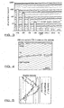
- Figure 4 illustrates a cross section of a TiN+C coating formed in accordance with one embodiment of the invention and shows how the coating comprises multilayers including the TiN intermediate layer and the Carbon top layer which forms the external surface of the coating once applied to the base or plate in the form of the steel substrate.
- Figure 5 illustrates the relative intensities of the Carbon, Titanium and Nitrogen during the formation of the coating.
- Carbon layer may also be doped with metal.
- the magnetron configuration used to produce the coatings is that as shown in Figure 1 .
- the Interfacial Contact Resistance (ICR) values of the coating were determined using the set up arrangement shown in Figure 2 .
- the sample is placed between two Gas Diffusion Layers (GDL's) and the total resistance is measured at a 140 N cm -1 after 300s of time.
- the resistance of the GDL alone is then also measured, after which, the value can be subtracted from the total resistance and divided by two to give the ICR of one surface.
- This arrangement method assumes that the bulk conductivity of the carbon GDL is negligible.
- Figure 3 illustrates the ICR measurements which have been obtained for coatings in accordance with the invention in comparison to other known coatings. It is clear that the provision of the multilayer coating in accordance with the invention significantly improves the surface conductivity of the article with e carbon outer layer having the greatest impact on the conductivity which can be achieved.
- the equipment used included a Zwick/Roell Z030 compression machine with a 50 kN load cell and a Thurlby Thandar BS407 micro ohm meter which utilised the four wire measurement method.
- Toray H120 GDLs, each of 1cm 2 were used and were conditioned before testing by compressing three times to 140 N cm -1 .
- the coating which is applied can be applied in two processes, a first process to apply the coating up to and including the at least one intermediate layer and a second process to apply a metal layer followed by the carbon containing layer or layers onto the intermediate layer.
- the said processes may be performed on two separate items of apparatus.
- a relatively thin metallic interlayer such as Cr or Ti on top of the previously deposited intermediate layer such as a nitride or carbide before introducing the carbon containing layer or layers so the adhesion between the intermediate layer and the carbon containing layer is improved.
- the present invention therefore provides a coating, an article which is coated with the same and a device incorporating the articles so formed which has advantages over the prior art in terms, of reduced cost, high durability, higher conductivity into the surface of the base or plate of the article, relatively high ability to be formed subsequent to the application of the coating and/or relatively high rates of deposition of the coating and hence throughput of the articles.
- electrochemical testing for corrosion resistance is performed as corrosion resistance is an important factor in gauging the likely practical performance of bipolar plate materials.
- Potentiodynamic experiments were carried out using an Autolab PGSTAT302N potentiostat connected to a computer.
- the electrochemical cell was a Bio-logic 250 ml jacketed flat corrosion cell with a 1 cm 2 sample area linked to a thermostatically controlled bath with a 1 cm 2 sample area. The cell was placed in a Faraday cage to reduce electrical interference from surrounding equipment. A C10-P5 Thermo Scientific circulating water bath was used to maintain the temperature of the cell at 70 °C.
- a three electrode setup was used where the working electrode was an as-received AISI316L 0.1 mm foil which had been coated by the PVD equipment described above, and was cleaned with acetone and dried prior to immersion.
- a Mercury/Mercury Sulphate Electrode (MSE) was used as the reference electrode rather than a Saturated Calomel Electrode (SCE) to avoid any possible chlorine contamination.
- MSE Mercury/Mercury Sulphate Electrode
- SCE Saturated Calomel Electrode
- a platinum mesh was used as the counter electrode and had a considerably greater geometric surface area than that of the working electrode.
- the electrolyte used was 250 ml of 0.5M H 2 SO 4 .
- the procedure involved bubbling the electrolyte with either air or hydrogen for 20 mins after which the delivery tube was withdrawn from the solution but left within the electrochemical cell to maintain the chosen atmosphere.
- the Open Circuit Potential (OCP) was then recorded for 40 mins.
- OCP Open Circuit Potential
- a potentiodynamic scan was then initiated recorded from 250 mV below the OCP value at a scan rate of 1 mVs -1 until the measured current density reached ⁇ 10 -2 Acm -1 .
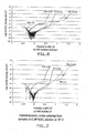
- the free corrosion potential (Ecorr) of TiN coating was less noble than the as-received stainless steel which was attributed to its natural affinity to oxidise. However, at higher potentials this presumed TiOx layer provided protection to the AISI316L foil.
- the Metal doped amorphous carbon coating chromium plus carbon doped with chromium coatings (labelled G-iC in the Figures 4 and 5 offer much more noble Ecorr values for the anode and cathode compared to AISI 316L.
- TiN+C coatings offer both noble Ecorr values and lower current densities at higher potentials when tested with bubbled air as shown in Figure 6 and bubbled hydrogen as shown in Figure 7 to simulate PEMFC, cathode and anode environments respectively.
- the coatings of the invention may also be applied using so-called reel to reel or coil to coil coating apparatus in order to provide a coating for a continous or segmented strip.
- This allows articles which have an optimised coating to be formed afterward and separated from the coated strip in subsequent processes.
- the adhesion and the mechanical characteristics of the coatings are advantageous to the retention of the desired properties, including electrical conductivity and corrosion resistance, of the surface of the formed articles.
- the coating may also confer advantages to the said forming process.
- the coating is of particular benefit for use in articles such as catalysts for electrolysers, and plates for fuel cells. It is found that significant costs savings can be achieved by for example, reducing the thickness of the coatings which are required to be applied whilst at least maintaining the performance levels such as by applying coatings of 0.4 ⁇ m compared to conventional coatings of 2 ⁇ m in thickness. It is also possible to reduce the manufacturing time of the finished, coated, article by increasing the deposition rates of the material used to form the coatings.
Landscapes
- Chemical & Material Sciences (AREA)
- Engineering & Computer Science (AREA)
- Chemical Kinetics & Catalysis (AREA)
- Mechanical Engineering (AREA)
- Materials Engineering (AREA)
- Organic Chemistry (AREA)
- Metallurgy (AREA)
- General Chemical & Material Sciences (AREA)
- Electrochemistry (AREA)
- Manufacturing & Machinery (AREA)
- Sustainable Energy (AREA)
- Life Sciences & Earth Sciences (AREA)
- Sustainable Development (AREA)
- Inorganic Chemistry (AREA)
- Composite Materials (AREA)
- Ceramic Engineering (AREA)
- Fuel Cell (AREA)
- Physical Vapour Deposition (AREA)
- Other Surface Treatments For Metallic Materials (AREA)
- Laminated Bodies (AREA)
Claims (23)
- Artikel (9), wobei der genannte Artikel eine Basis oder Platte aufweist, gebildet aus einem elektrisch leitfähigen Material und einer darauf aufgebrachten Beschichtung, um wenigstens einen Teil der Außenfläche derselben zu bedecken, wobei die genannte Beschichtung, wenigstens auf ihrer Außenfläche, eine leitfähige Kohlenstoffmaterialschicht aufweist und zwischen der genannten Außenfläche und der Basis wenigstens eine intermediäre Schicht aus einem oder mehreren elektrisch leitfähigen Materialien vorgesehen ist, und das Kohlenstoffmaterial der Kohlenstoffmaterialschicht eine im Wesentlichen graphitische sp2-Form wenigstens an und/oder neben der Außenfläche der Beschichtung hat, und dadurch gekennzeichnet, dass die Beschichtung durch Abstufen des sp2/sp3-Kohlenstoffbindungsverhältnisses in der im Wesentlichen Kohlenstoffmaterialschicht abgestuft ist, so dass das Verhältnis von sp2 zu sp3 in Richtung der Außenfläche der Beschichtung zunimmt.
- Artikel nach Anspruch 1, wobei die wenigstens eine intermediäre Schicht aus Nitrid- und/oder Carbidmaterial gebildet ist.
- Artikel nach Anspruch 2, wobei die Nitrid- und/oder Carbidschicht eine beliebige, oder eine beliebige Kombination von, Haftung für die Beschichtung an der Basis, einer Barrierenschicht für das Basismaterial und/oder Korrosionsschutz für das Basismaterial bereitstellt.
- Artikel nach Anspruch 1, wobei die Beschichtung eine Metall- oder Metalllegierungsschicht und/oder eine Metalloxidschicht beinhaltet.
- Artikel nach Anspruch 1, wobei der Übergang zwischen der im Wesentlichen Kohlenstoffmaterialschicht und wenigstens einer intermediären Schicht abgestuft ist.
- Artikel nach Anspruch 1, wobei die Beschichtung auf der Basis von Dichte abgestuft ist.
- Artikel nach Anspruch 1, wobei, falls vorhanden, die Edelmetallschicht so positioniert ist, dass das Kohlenstoffmaterial darauf aufgebracht ist, um die Außenfläche der Beschichtung zu bilden.
- Artikel nach Anspruch 1, wobei die Basis oder Platte eine bipolare Platte zur Verwendung als Teil einer Brennstoffzelle ist.
- Artikel nach Anspruch 1, wobei die Schicht der Basis, auf die die Beschichtung aufgebracht wird, und/oder eine beliebige Beschichtungssubschicht, mit einem Metallatom dotiert ist.
- Artikel nach Anspruch 1, wobei die wenigstens eine intermediäre Schicht ein elektrisch leitfähiges Nitrid, Carbid oder Carbonitrid und/oder eine Verbindung aus einem Übergangsmaterial ist.
- Artikel nach Anspruch 1, wobei die genannte wenigstens eine intermediäre Schicht eine Interfacial Contact Resistance (ICR) von < 25 m«-cE und vorzugsweise < 15 m«-cmE hat und die wenigstens eine Kohlenstoffschicht eine ICR von < 15 m«-cmE hat.
- Artikel nach Anspruch 1, wobei die gemischten Kohlenstoff-Metall-Schichten einen Metallgehalt von 0,1 bis 10 Atom-% haben.
- Artikel nach Anspruch 1, wobei die Oberfläche der Beschichtung einen Kontaktwinkel zu Wasser im Bereich von 30 bis 150° hat.
- Artikel nach Anspruch 1, wobei die Außenfläche der Beschichtung einen Oberflächenbereich von mehr als dem 30fachen von dem der scheinbaren oder projizierten Fläche der Beschichtung hat.
- Artikel nach Anspruch 1, wobei eine metallische Zwischenschicht auf der genannten wenigstens einen intermediären Schicht vorgesehen ist.
- Verfahren zum Bilden einer Beschichtung auf einem Artikel (9) mit einer Basis oder Platte mit einem leitfähigen Metall, wobei das Verfahren die folgenden Schritte beinhaltet: Aufbringen einer Beschichtung mit wenigstens einer nichthydrierten amorphen Kohlenstoffschicht durch Magnetron-Sputtern von wenigstens einem Graphit-Target (16, 18) zum Bilden einer Außenfläche auf wenigstens einem Teil der Basis oder Platte und, vor dem Auftragen der genannten nichthydrierten amorphen Kohlenstoffschicht, Aufbringen von wenigstens einer intermediären Schicht aus einem leitfähigen Material zwischen der genannten Basis oder Platte und der genannten nichthydrierten amorphen Kohlenstoffschicht, wobei die im Wesentlichen Kohlenstoffschicht eine im Wesentlichen graphitische sp2-Form wenigstens an und/oder neben der Außenfläche der Beschichtung hat, gekennzeichnet durch Abstufen des sp2/sp3-Kohlenstoffbindungsverhältnisses in der nichthydrierten amorphen Kohlenstoffschicht, so dass das Verhältnis von sp2 bis sp3 in Richtung der Außenfläche der Beschichtung zunimmt.
- Verfahren nach Anspruch 16, wobei die Oberfläche der Basis oder Platte, auf die die Beschichtung aufgebracht werden soll, vorbehandelt wird, um eine Oberflächentopografie zum Unterstützen der Haftung der Beschichtung an der Basis oder Platte und/oder zum Erhöhen der Leitfähigkeit des Artikels und/oder zum Beeinflussen der nachfolgenden Keimbildung und des Wachstums von einer oder mehreren evtl. aufgebrachten nachfolgenden Schichten bereitzustellen.
- Verfahren nach Anspruch 16, wobei wenigstens eine nichthydrierte amorphe Kohlenstoff-Metall-Schicht durch Aufsputtern von Composite-Kohlenstoff-Metall-Targets einer geeigneten Zusammensetzung aufgebracht wird.
- Verfahren nach Anspruch 16, wobei mehrere Kohlenstoff-Metall-Schichten durch Aufsputtern von Graphit-Targets mit metallischen Einsätzen hergestellt werden.
- Verfahren nach Anspruch 16, wobei das Verfahren den Anfangsschritt des Entfernens von Oxidation von der Außenfläche der Basis oder Platte des Artikels durch Sputter-Reinigen und/oder chemisches Ätzen beinhaltet.
- Verfahren nach Anspruch 20, wobei nach dem Entfernen von Oxidation die Außenfläche der Basis oder Platte, auf die die Beschichtung aufgebracht werden soll, vorbehandelt wird, um einen Aufrauungseffekt darauf zu erzielen.
- Verfahren nach Anspruch 16, wobei die Beschichtung bis zu und einschließlich der intermediären Schicht mit einem ersten Materialauftragsprozess aufgebracht wird und der Rest der Beschichtung ganz oder teilweise mit einem zweiten Materialauftragsprozess aufgebracht wird.
- Verfahren nach Anspruch 16, wobei eine metallische Schicht auf die zuvor aufgebrachte wenigstens eine intermediäre Schicht aufgebracht wird, bevor eine kohlenstoffhaltige Schicht aufgebracht wird.
Applications Claiming Priority (2)
| Application Number | Priority Date | Filing Date | Title |
|---|---|---|---|
| GBGB1203219.9A GB201203219D0 (en) | 2012-02-24 | 2012-02-24 | Coating with conductive and corrosion resistance characteristics |
| PCT/GB2013/050465 WO2013124690A1 (en) | 2012-02-24 | 2013-02-25 | Coating with conductive and corrosion resistance characteristics |
Publications (2)
| Publication Number | Publication Date |
|---|---|
| EP2817430A1 EP2817430A1 (de) | 2014-12-31 |
| EP2817430B1 true EP2817430B1 (de) | 2018-12-19 |
Family
ID=45991681
Family Applications (1)
| Application Number | Title | Priority Date | Filing Date |
|---|---|---|---|
| EP13711932.7A Active EP2817430B1 (de) | 2012-02-24 | 2013-02-25 | Leitfähige und korrosionsbeständige beschichtung |
Country Status (7)
| Country | Link |
|---|---|
| US (1) | US20150037710A1 (de) |
| EP (1) | EP2817430B1 (de) |
| KR (1) | KR20140130505A (de) |
| CN (1) | CN104204274B (de) |
| CA (1) | CA2864844C (de) |
| GB (1) | GB201203219D0 (de) |
| WO (1) | WO2013124690A1 (de) |
Cited By (1)
| Publication number | Priority date | Publication date | Assignee | Title |
|---|---|---|---|---|
| DE102019116000A1 (de) * | 2019-06-12 | 2020-12-17 | Schaeffler Technologies AG & Co. KG | Schichtsystem zum Beschichten einer Bipolarplatte, sowie Bipolarplatte und Brennstoffzelle |
Families Citing this family (48)
| Publication number | Priority date | Publication date | Assignee | Title |
|---|---|---|---|---|
| JP5999190B2 (ja) | 2012-10-01 | 2016-09-28 | 日産自動車株式会社 | インライン式コーティング装置、インライン式コーティング方法、およびセパレータ |
| CN105304915A (zh) * | 2014-07-17 | 2016-02-03 | 北京锦源创新科技有限公司 | 一种用于燃料电池的双极板及其制造方法 |
| CN104577144B (zh) * | 2015-01-27 | 2017-12-22 | 大连理工常州研究院有限公司 | 一种氮化增强表面的燃料电池用双极板及其制备方法 |
| US10003089B2 (en) | 2015-02-11 | 2018-06-19 | Ford Global Technologies, Llc | Multilayer coating for corrosion resistant metal bipolar plate for a PEMFC |
| US10135077B2 (en) | 2015-02-12 | 2018-11-20 | Ford Global Technologies, Llc | Corrosion resistant metal bipolar plate for a PEMFC including a radical scavenger |
| MX2017012154A (es) * | 2015-03-20 | 2018-02-09 | Aperam | Tira o lamina metalica que tiene un recubrimiento de nitruro de cromo, placa bipolar y su metodo de fabricacion asociado. |
| CN107429379B (zh) * | 2015-03-20 | 2019-09-24 | 艾普伦 | 金属带、双极板以及相关的制造方法 |
| JP6464897B2 (ja) * | 2015-04-08 | 2019-02-06 | トヨタ自動車株式会社 | 燃料電池スタック |
| DE102015208644A1 (de) | 2015-05-11 | 2016-11-17 | Schaeffler Technologies AG & Co. KG | Bauteil, Verwendung des Bauteils sowie Verfahren zur Herstellung des Bauteils |
| US9926622B2 (en) | 2015-11-12 | 2018-03-27 | Uchicago Argonne, Llc | Methods for forming pitting resistant carbon coating |
| US10036472B2 (en) * | 2016-03-04 | 2018-07-31 | Kabushiki Kaisha Riken | Sliding member and piston ring |
| CN109154061B (zh) * | 2016-04-22 | 2021-07-13 | 欧瑞康表面处理解决方案股份公司普费菲孔 | 借助HIPIMS的具有减少的生长缺陷的TiCN |
| CN106252682B (zh) * | 2016-08-17 | 2019-07-12 | 上海交通大学 | 抑制柱状晶的燃料电池金属极板多相涂层及其制备方法 |
| CN106374116B (zh) * | 2016-12-01 | 2019-09-06 | 上海电机学院 | 一种燃料电池金属双极板上的高熵合金复合涂层和工艺 |
| CN107195920B (zh) * | 2017-06-15 | 2019-10-11 | 常州翊迈新材料科技有限公司 | 燃料电池兼具导电和耐蚀功能的涂层材料 |
| CN109868483B (zh) * | 2017-12-04 | 2021-05-07 | 中国科学院大连化学物理研究所 | 一种带抗腐蚀保护层的水电解池金属双极板及制备和应用 |
| CN109536905B (zh) * | 2018-12-13 | 2020-09-22 | 西安工程大学 | 一种铜表面用TiC-Si固溶体导电涂层的制备方法 |
| CN109852932A (zh) * | 2019-02-20 | 2019-06-07 | 金华市畔星科技有限公司 | 氢燃料电池金属双极板及其制备方法 |
| GB201910455D0 (en) * | 2019-07-22 | 2019-09-04 | Teer Coatings Ltd | Coating for the surface of an article and process for forming the coating |
| EP3778982B1 (de) | 2019-08-14 | 2023-07-05 | IHI Hauzer Techno Coating B.V. | Verfahren zum beschichten einer oder mehrerer metallkomponenten eines brennstoffzellenstapels, komponente eines brennstoffzellenstapels und vorrichtung zum beschichten einer oder mehrerer komponenten eines brennstoffzellenstapels |
| TWI728449B (zh) * | 2019-09-02 | 2021-05-21 | 禾達材料科技股份有限公司 | 應用於生物試片的複合式材料結構及其製作方法 |
| CN110863166B (zh) * | 2019-11-18 | 2022-09-13 | 和县科嘉阀门铸造有限公司 | 一种提高奥氏体不锈钢阀门抗应力腐蚀的方法 |
| CN112993293A (zh) * | 2019-12-14 | 2021-06-18 | 中国科学院大连化学物理研究所 | 一种燃料电池金属双极板及其制备方法 |
| CN110983283B (zh) * | 2019-12-20 | 2021-12-24 | 欧伊翔 | 氢燃料电池金属双极板用Ti/TiCN纳米涂层的制备方法及设备 |
| CN111092242B (zh) * | 2020-02-27 | 2021-11-09 | 江苏微导纳米科技股份有限公司 | 一种质子交换膜燃料电池金属双极板多纳米涂层结构的制备方法 |
| JP7313577B2 (ja) * | 2020-07-14 | 2023-07-24 | ナノフィルム テクノロジーズ インターナショナル リミテッド | 炭素被覆された水素燃料電池用双極板 |
| EP3964604A1 (de) | 2020-09-03 | 2022-03-09 | IHI Ionbond AG | Dotiertes dlc für bipolarplatten (bpp) und tribologische anwendungen |
| CN112609165B (zh) * | 2020-12-15 | 2022-11-29 | 辽宁科技大学 | 一种不锈钢基燃料电池双极板表面复合涂层及其制备方法 |
| CN116997673A (zh) * | 2021-03-23 | 2023-11-03 | 日东电工株式会社 | 电极及其制造方法 |
| JPWO2022202941A1 (de) * | 2021-03-23 | 2022-09-29 | ||
| CN113097520B (zh) * | 2021-03-29 | 2022-11-01 | 深圳扑浪创新科技有限公司 | 一种不锈钢双极板及其制备方法 |
| CN113675417A (zh) * | 2021-07-15 | 2021-11-19 | 国家电投集团氢能科技发展有限公司 | 燃料电池、燃料电池双极板及其制备方法 |
| FR3126428B1 (fr) * | 2021-08-31 | 2026-02-27 | Hydromecanique & Frottement | Procédé de dépôt de carbone sur un substrat |
| CN113860916B (zh) * | 2021-09-14 | 2022-10-14 | 内蒙古科技大学 | 耐侵蚀碳化铌钛涂层、耐侵蚀碳化硅容器及其制备方法和应用 |
| CN114023986B (zh) * | 2021-09-28 | 2022-12-16 | 上海治臻新能源股份有限公司 | 一种用于燃料电池钛基材双极板的复合涂层及其制备方法 |
| CN114015987B (zh) * | 2021-10-08 | 2022-11-29 | 上海治臻新能源股份有限公司 | 一种降低基材离子污染的高延展性金属极板预涂层 |
| CN116525864B (zh) * | 2022-01-20 | 2024-07-02 | 纳峰真空镀膜(上海)有限公司 | 碳涂层电极的改进 |
| JP7558429B2 (ja) | 2022-01-20 | 2024-09-30 | ナノフィルム テクノロジーズ インターナショナル リミテッド | 炭素被覆電極 |
| CN114665114A (zh) * | 2022-04-11 | 2022-06-24 | 上海电气集团股份有限公司 | 一种多层复合碳涂层及其制备方法和应用 |
| CN114843542B (zh) * | 2022-05-16 | 2024-01-02 | 上海交通大学内蒙古研究院 | 一种燃料电池金属极板陶瓷相低温形核纳米涂层制备方法 |
| CN114990476B (zh) * | 2022-05-17 | 2023-05-23 | 华南理工大学 | 一种氮掺杂四面体非晶碳薄膜及其制备方法和应用 |
| CN114976089B (zh) * | 2022-05-27 | 2024-04-12 | 上海电气集团股份有限公司 | 一种含涂层的金属双极板及其制备方法 |
| CN115000444B (zh) * | 2022-06-21 | 2023-12-29 | 上海电气集团股份有限公司 | 多层复合碳涂层及其制备方法、应用、燃料电池双极板、燃料电池 |
| BE1030680B1 (fr) | 2022-06-29 | 2024-01-29 | Centre De Recherches Metallurgiques Asbl Centrum Voor Res In De Metallurgie Vzw | Revetement d'un substrat metallique avec une couche externe carbonee obtenue par la methode sol-gel |
| CN115976479A (zh) * | 2022-12-14 | 2023-04-18 | 上海福宜真空设备有限公司 | 制备双极板表面耐腐蚀涂层的方法及真空镀膜设备 |
| CN116314854A (zh) * | 2023-01-10 | 2023-06-23 | 中国机械总院集团武汉材料保护研究所有限公司 | 一种氢燃料电池金属双极板用导电耐蚀涂层及其制备方法 |
| CN116154203A (zh) * | 2023-02-17 | 2023-05-23 | 深圳市长盈精密技术股份有限公司 | 质子交换膜燃料电池抗腐蚀涂层及其制备方法和燃料电池 |
| FR3146695A1 (fr) * | 2023-03-15 | 2024-09-20 | Hydromecanique Et Frottement | Pièce revêtue d’une couche à base de carbone |
Family Cites Families (7)
| Publication number | Priority date | Publication date | Assignee | Title |
|---|---|---|---|---|
| US6726993B2 (en) * | 1997-12-02 | 2004-04-27 | Teer Coatings Limited | Carbon coatings, method and apparatus for applying them, and articles bearing such coatings |
| CN1352812A (zh) * | 1999-07-19 | 2002-06-05 | 住友电气工业株式会社 | 用于固体聚合物电解质型燃料电池的分离器 |
| JP4147925B2 (ja) * | 2002-12-04 | 2008-09-10 | トヨタ自動車株式会社 | 燃料電池用セパレータ |
| US7897295B2 (en) * | 2005-12-20 | 2011-03-01 | GM Global Technology Operations LLC | Surface engineering of bipolar plate materials for better water management |
| GB0613877D0 (en) * | 2006-07-13 | 2006-08-23 | Teer Coatings Ltd | Coating apparatus and coating for an article |
| EP2044237B1 (de) * | 2006-07-13 | 2020-12-16 | Teer Coatings Limited | Verfahren zur beschichtung |
| US8900771B2 (en) * | 2006-08-17 | 2014-12-02 | GM Global Technology Operations LLC | Non-noble metal inexpensive conductive coatings for fuel cell bipolar plates |
-
2012
- 2012-02-24 GB GBGB1203219.9A patent/GB201203219D0/en not_active Ceased
-
2013
- 2013-02-25 WO PCT/GB2013/050465 patent/WO2013124690A1/en not_active Ceased
- 2013-02-25 US US14/379,703 patent/US20150037710A1/en not_active Abandoned
- 2013-02-25 CA CA2864844A patent/CA2864844C/en active Active
- 2013-02-25 CN CN201380010775.0A patent/CN104204274B/zh active Active
- 2013-02-25 EP EP13711932.7A patent/EP2817430B1/de active Active
- 2013-02-25 KR KR1020147026666A patent/KR20140130505A/ko not_active Withdrawn
Non-Patent Citations (1)
| Title |
|---|
| None * |
Cited By (1)
| Publication number | Priority date | Publication date | Assignee | Title |
|---|---|---|---|---|
| DE102019116000A1 (de) * | 2019-06-12 | 2020-12-17 | Schaeffler Technologies AG & Co. KG | Schichtsystem zum Beschichten einer Bipolarplatte, sowie Bipolarplatte und Brennstoffzelle |
Also Published As
| Publication number | Publication date |
|---|---|
| CA2864844A1 (en) | 2013-08-29 |
| US20150037710A1 (en) | 2015-02-05 |
| WO2013124690A1 (en) | 2013-08-29 |
| GB201203219D0 (en) | 2012-04-11 |
| CN104204274A (zh) | 2014-12-10 |
| CN104204274B (zh) | 2018-02-09 |
| EP2817430A1 (de) | 2014-12-31 |
| KR20140130505A (ko) | 2014-11-10 |
| CA2864844C (en) | 2021-06-01 |
Similar Documents
| Publication | Publication Date | Title |
|---|---|---|
| EP2817430B1 (de) | Leitfähige und korrosionsbeständige beschichtung | |
| Zhang et al. | Strategy of alternating bias voltage on corrosion resistance and interfacial conductivity enhancement of TiCx/aC coatings on metallic bipolar plates in PEMFCs | |
| Feng et al. | Conductive amorphous carbon-coated 316L stainless steel as bipolar plates in polymer electrolyte membrane fuel cells | |
| Feng et al. | C/CrN multilayer coating for polymer electrolyte membrane fuel cell metallic bipolar plates | |
| Li et al. | Investigation of single-layer and multilayer coatings for aluminum bipolar plate in polymer electrolyte membrane fuel cell | |
| EP2157645B1 (de) | Metalltrennglied für eine brennstoffzelle und prozess zur herstellung des metalltrennglieds | |
| US10003089B2 (en) | Multilayer coating for corrosion resistant metal bipolar plate for a PEMFC | |
| EP2124278A1 (de) | Brennstoffzellentrennglied, verfahren zur herstellung eines brennstoffzellentrennglieds und brennstoffzelle | |
| CN100550489C (zh) | 燃料电池用隔板及其制造方法 | |
| KR20180022869A (ko) | 고체 고분자형 연료 전지의 세퍼레이터용 금속판 및 그 제조용 금속판 | |
| Wang et al. | Self-passivating carbon film as bipolar plate protective coating in polymer electrolyte membrane fuel cell | |
| TWI610490B (zh) | 固體高分子形燃料電池之分隔件用金屬板 | |
| CN115663224A (zh) | 质子交换膜燃料电池双极板金属复合涂层及其制备方法 | |
| Yu et al. | Enhanced performance of Ti–Nb–N film modified 316L stainless steel and Ti bipolar plates for proton exchange membrane water electrolyser | |
| JP2018006300A (ja) | 燃料電池用金属セパレータ及びこれを用いた燃料電池 | |
| JP4516628B2 (ja) | 燃料電池用金属セパレータおよびその製造方法 | |
| CN110970626B (zh) | 燃料电池双极板及其涂层 | |
| KR20210035231A (ko) | 부식 저항을 제공하는 전도성 층을 적용하기 전에 부동태화 금속 기판의 접촉 저항을 감소시키는 코팅 | |
| KR101394834B1 (ko) | 탄소-금속 교대 반복 코팅을 이용한 연료전지용 금속 분리판 및 그 제조 방법 | |
| CN114447356A (zh) | 一种亲水涂层及其制备方法 | |
| Xu et al. | High performance Nb/NbN coatings fabricated by bias-voltage-controlled magnetron sputtering for water electrolyzer bipolar plates anode anti-corrosion application | |
| Chen et al. | Investigating the effect of bias voltage on corrosion resistance and conductivity of CrN coating in simulated PEMFC environment | |
| KR100867819B1 (ko) | 연료전지용 금속분리판의 표면층 및 이의 형성방법 | |
| JP2024530524A (ja) | 炭素系層で被覆された部品 | |
| Lee et al. | Long-term corrosion resistance of HiPIMS deposited high entropy alloy coatings in alkaline simulated seawater environments |
Legal Events
| Date | Code | Title | Description |
|---|---|---|---|
| PUAI | Public reference made under article 153(3) epc to a published international application that has entered the european phase |
Free format text: ORIGINAL CODE: 0009012 |
|
| 17P | Request for examination filed |
Effective date: 20140922 |
|
| AK | Designated contracting states |
Kind code of ref document: A1 Designated state(s): AL AT BE BG CH CY CZ DE DK EE ES FI FR GB GR HR HU IE IS IT LI LT LU LV MC MK MT NL NO PL PT RO RS SE SI SK SM TR |
|
| AX | Request for extension of the european patent |
Extension state: BA ME |
|
| DAX | Request for extension of the european patent (deleted) | ||
| STAA | Information on the status of an ep patent application or granted ep patent |
Free format text: STATUS: EXAMINATION IS IN PROGRESS |
|
| 17Q | First examination report despatched |
Effective date: 20161222 |
|
| RIC1 | Information provided on ipc code assigned before grant |
Ipc: H01M 8/0228 20160101ALI20180531BHEP Ipc: H01M 8/0206 20160101ALI20180531BHEP Ipc: H01M 4/88 20060101ALI20180531BHEP Ipc: H01M 8/0213 20160101ALI20180531BHEP Ipc: C23C 14/06 20060101AFI20180531BHEP Ipc: H01M 8/021 20160101ALI20180531BHEP Ipc: H01M 8/0215 20160101ALI20180531BHEP Ipc: C23C 14/02 20060101ALI20180531BHEP Ipc: C23C 14/35 20060101ALI20180531BHEP Ipc: C23C 28/00 20060101ALI20180531BHEP |
|
| GRAP | Despatch of communication of intention to grant a patent |
Free format text: ORIGINAL CODE: EPIDOSNIGR1 |
|
| STAA | Information on the status of an ep patent application or granted ep patent |
Free format text: STATUS: GRANT OF PATENT IS INTENDED |
|
| INTG | Intention to grant announced |
Effective date: 20180711 |
|
| GRAS | Grant fee paid |
Free format text: ORIGINAL CODE: EPIDOSNIGR3 |
|
| GRAA | (expected) grant |
Free format text: ORIGINAL CODE: 0009210 |
|
| STAA | Information on the status of an ep patent application or granted ep patent |
Free format text: STATUS: THE PATENT HAS BEEN GRANTED |
|
| AK | Designated contracting states |
Kind code of ref document: B1 Designated state(s): AL AT BE BG CH CY CZ DE DK EE ES FI FR GB GR HR HU IE IS IT LI LT LU LV MC MK MT NL NO PL PT RO RS SE SI SK SM TR |
|
| REG | Reference to a national code |
Ref country code: GB Ref legal event code: FG4D |
|
| REG | Reference to a national code |
Ref country code: CH Ref legal event code: EP |
|
| REG | Reference to a national code |
Ref country code: DE Ref legal event code: R096 Ref document number: 602013048389 Country of ref document: DE |
|
| REG | Reference to a national code |
Ref country code: IE Ref legal event code: FG4D |
|
| REG | Reference to a national code |
Ref country code: AT Ref legal event code: REF Ref document number: 1078799 Country of ref document: AT Kind code of ref document: T Effective date: 20190115 |
|
| REG | Reference to a national code |
Ref country code: NL Ref legal event code: MP Effective date: 20181219 |
|
| PG25 | Lapsed in a contracting state [announced via postgrant information from national office to epo] |
Ref country code: NO Free format text: LAPSE BECAUSE OF FAILURE TO SUBMIT A TRANSLATION OF THE DESCRIPTION OR TO PAY THE FEE WITHIN THE PRESCRIBED TIME-LIMIT Effective date: 20190319 Ref country code: BG Free format text: LAPSE BECAUSE OF FAILURE TO SUBMIT A TRANSLATION OF THE DESCRIPTION OR TO PAY THE FEE WITHIN THE PRESCRIBED TIME-LIMIT Effective date: 20190319 Ref country code: LT Free format text: LAPSE BECAUSE OF FAILURE TO SUBMIT A TRANSLATION OF THE DESCRIPTION OR TO PAY THE FEE WITHIN THE PRESCRIBED TIME-LIMIT Effective date: 20181219 Ref country code: FI Free format text: LAPSE BECAUSE OF FAILURE TO SUBMIT A TRANSLATION OF THE DESCRIPTION OR TO PAY THE FEE WITHIN THE PRESCRIBED TIME-LIMIT Effective date: 20181219 Ref country code: LV Free format text: LAPSE BECAUSE OF FAILURE TO SUBMIT A TRANSLATION OF THE DESCRIPTION OR TO PAY THE FEE WITHIN THE PRESCRIBED TIME-LIMIT Effective date: 20181219 Ref country code: HR Free format text: LAPSE BECAUSE OF FAILURE TO SUBMIT A TRANSLATION OF THE DESCRIPTION OR TO PAY THE FEE WITHIN THE PRESCRIBED TIME-LIMIT Effective date: 20181219 |
|
| REG | Reference to a national code |
Ref country code: LT Ref legal event code: MG4D |
|
| REG | Reference to a national code |
Ref country code: AT Ref legal event code: MK05 Ref document number: 1078799 Country of ref document: AT Kind code of ref document: T Effective date: 20181219 |
|
| PG25 | Lapsed in a contracting state [announced via postgrant information from national office to epo] |
Ref country code: RS Free format text: LAPSE BECAUSE OF FAILURE TO SUBMIT A TRANSLATION OF THE DESCRIPTION OR TO PAY THE FEE WITHIN THE PRESCRIBED TIME-LIMIT Effective date: 20181219 Ref country code: SE Free format text: LAPSE BECAUSE OF FAILURE TO SUBMIT A TRANSLATION OF THE DESCRIPTION OR TO PAY THE FEE WITHIN THE PRESCRIBED TIME-LIMIT Effective date: 20181219 Ref country code: AL Free format text: LAPSE BECAUSE OF FAILURE TO SUBMIT A TRANSLATION OF THE DESCRIPTION OR TO PAY THE FEE WITHIN THE PRESCRIBED TIME-LIMIT Effective date: 20181219 Ref country code: GR Free format text: LAPSE BECAUSE OF FAILURE TO SUBMIT A TRANSLATION OF THE DESCRIPTION OR TO PAY THE FEE WITHIN THE PRESCRIBED TIME-LIMIT Effective date: 20190320 |
|
| PG25 | Lapsed in a contracting state [announced via postgrant information from national office to epo] |
Ref country code: NL Free format text: LAPSE BECAUSE OF FAILURE TO SUBMIT A TRANSLATION OF THE DESCRIPTION OR TO PAY THE FEE WITHIN THE PRESCRIBED TIME-LIMIT Effective date: 20181219 |
|
| PG25 | Lapsed in a contracting state [announced via postgrant information from national office to epo] |
Ref country code: IT Free format text: LAPSE BECAUSE OF FAILURE TO SUBMIT A TRANSLATION OF THE DESCRIPTION OR TO PAY THE FEE WITHIN THE PRESCRIBED TIME-LIMIT Effective date: 20181219 Ref country code: PT Free format text: LAPSE BECAUSE OF FAILURE TO SUBMIT A TRANSLATION OF THE DESCRIPTION OR TO PAY THE FEE WITHIN THE PRESCRIBED TIME-LIMIT Effective date: 20190419 Ref country code: ES Free format text: LAPSE BECAUSE OF FAILURE TO SUBMIT A TRANSLATION OF THE DESCRIPTION OR TO PAY THE FEE WITHIN THE PRESCRIBED TIME-LIMIT Effective date: 20181219 Ref country code: CZ Free format text: LAPSE BECAUSE OF FAILURE TO SUBMIT A TRANSLATION OF THE DESCRIPTION OR TO PAY THE FEE WITHIN THE PRESCRIBED TIME-LIMIT Effective date: 20181219 Ref country code: PL Free format text: LAPSE BECAUSE OF FAILURE TO SUBMIT A TRANSLATION OF THE DESCRIPTION OR TO PAY THE FEE WITHIN THE PRESCRIBED TIME-LIMIT Effective date: 20181219 |
|
| PG25 | Lapsed in a contracting state [announced via postgrant information from national office to epo] |
Ref country code: IS Free format text: LAPSE BECAUSE OF FAILURE TO SUBMIT A TRANSLATION OF THE DESCRIPTION OR TO PAY THE FEE WITHIN THE PRESCRIBED TIME-LIMIT Effective date: 20190419 Ref country code: SK Free format text: LAPSE BECAUSE OF FAILURE TO SUBMIT A TRANSLATION OF THE DESCRIPTION OR TO PAY THE FEE WITHIN THE PRESCRIBED TIME-LIMIT Effective date: 20181219 Ref country code: RO Free format text: LAPSE BECAUSE OF FAILURE TO SUBMIT A TRANSLATION OF THE DESCRIPTION OR TO PAY THE FEE WITHIN THE PRESCRIBED TIME-LIMIT Effective date: 20181219 Ref country code: EE Free format text: LAPSE BECAUSE OF FAILURE TO SUBMIT A TRANSLATION OF THE DESCRIPTION OR TO PAY THE FEE WITHIN THE PRESCRIBED TIME-LIMIT Effective date: 20181219 Ref country code: SM Free format text: LAPSE BECAUSE OF FAILURE TO SUBMIT A TRANSLATION OF THE DESCRIPTION OR TO PAY THE FEE WITHIN THE PRESCRIBED TIME-LIMIT Effective date: 20181219 |
|
| REG | Reference to a national code |
Ref country code: DE Ref legal event code: R097 Ref document number: 602013048389 Country of ref document: DE |
|
| REG | Reference to a national code |
Ref country code: CH Ref legal event code: PL |
|
| PLBE | No opposition filed within time limit |
Free format text: ORIGINAL CODE: 0009261 |
|
| STAA | Information on the status of an ep patent application or granted ep patent |
Free format text: STATUS: NO OPPOSITION FILED WITHIN TIME LIMIT |
|
| PG25 | Lapsed in a contracting state [announced via postgrant information from national office to epo] |
Ref country code: MC Free format text: LAPSE BECAUSE OF FAILURE TO SUBMIT A TRANSLATION OF THE DESCRIPTION OR TO PAY THE FEE WITHIN THE PRESCRIBED TIME-LIMIT Effective date: 20181219 Ref country code: AT Free format text: LAPSE BECAUSE OF FAILURE TO SUBMIT A TRANSLATION OF THE DESCRIPTION OR TO PAY THE FEE WITHIN THE PRESCRIBED TIME-LIMIT Effective date: 20181219 Ref country code: LU Free format text: LAPSE BECAUSE OF NON-PAYMENT OF DUE FEES Effective date: 20190225 Ref country code: DK Free format text: LAPSE BECAUSE OF FAILURE TO SUBMIT A TRANSLATION OF THE DESCRIPTION OR TO PAY THE FEE WITHIN THE PRESCRIBED TIME-LIMIT Effective date: 20181219 |
|
| REG | Reference to a national code |
Ref country code: BE Ref legal event code: MM Effective date: 20190228 |
|
| 26N | No opposition filed |
Effective date: 20190920 |
|
| REG | Reference to a national code |
Ref country code: IE Ref legal event code: MM4A |
|
| PG25 | Lapsed in a contracting state [announced via postgrant information from national office to epo] |
Ref country code: CH Free format text: LAPSE BECAUSE OF NON-PAYMENT OF DUE FEES Effective date: 20190228 Ref country code: LI Free format text: LAPSE BECAUSE OF NON-PAYMENT OF DUE FEES Effective date: 20190228 |
|
| PG25 | Lapsed in a contracting state [announced via postgrant information from national office to epo] |
Ref country code: IE Free format text: LAPSE BECAUSE OF NON-PAYMENT OF DUE FEES Effective date: 20190225 |
|
| PG25 | Lapsed in a contracting state [announced via postgrant information from national office to epo] |
Ref country code: BE Free format text: LAPSE BECAUSE OF NON-PAYMENT OF DUE FEES Effective date: 20190228 Ref country code: SI Free format text: LAPSE BECAUSE OF FAILURE TO SUBMIT A TRANSLATION OF THE DESCRIPTION OR TO PAY THE FEE WITHIN THE PRESCRIBED TIME-LIMIT Effective date: 20181219 |
|
| PG25 | Lapsed in a contracting state [announced via postgrant information from national office to epo] |
Ref country code: TR Free format text: LAPSE BECAUSE OF FAILURE TO SUBMIT A TRANSLATION OF THE DESCRIPTION OR TO PAY THE FEE WITHIN THE PRESCRIBED TIME-LIMIT Effective date: 20181219 |
|
| PG25 | Lapsed in a contracting state [announced via postgrant information from national office to epo] |
Ref country code: MT Free format text: LAPSE BECAUSE OF NON-PAYMENT OF DUE FEES Effective date: 20190225 |
|
| PG25 | Lapsed in a contracting state [announced via postgrant information from national office to epo] |
Ref country code: CY Free format text: LAPSE BECAUSE OF FAILURE TO SUBMIT A TRANSLATION OF THE DESCRIPTION OR TO PAY THE FEE WITHIN THE PRESCRIBED TIME-LIMIT Effective date: 20181219 |
|
| PG25 | Lapsed in a contracting state [announced via postgrant information from national office to epo] |
Ref country code: HU Free format text: LAPSE BECAUSE OF FAILURE TO SUBMIT A TRANSLATION OF THE DESCRIPTION OR TO PAY THE FEE WITHIN THE PRESCRIBED TIME-LIMIT; INVALID AB INITIO Effective date: 20130225 |
|
| PG25 | Lapsed in a contracting state [announced via postgrant information from national office to epo] |
Ref country code: MK Free format text: LAPSE BECAUSE OF FAILURE TO SUBMIT A TRANSLATION OF THE DESCRIPTION OR TO PAY THE FEE WITHIN THE PRESCRIBED TIME-LIMIT Effective date: 20181219 |
|
| P01 | Opt-out of the competence of the unified patent court (upc) registered |
Effective date: 20230403 |
|
| PGFP | Annual fee paid to national office [announced via postgrant information from national office to epo] |
Ref country code: GB Payment date: 20260120 Year of fee payment: 14 |
|
| PGFP | Annual fee paid to national office [announced via postgrant information from national office to epo] |
Ref country code: DE Payment date: 20260121 Year of fee payment: 14 |
|
| PGFP | Annual fee paid to national office [announced via postgrant information from national office to epo] |
Ref country code: FR Payment date: 20260120 Year of fee payment: 14 |