EP2817609B1 - Gewebeprobentisch für optisches gewebeschnittmikroskop - Google Patents
Gewebeprobentisch für optisches gewebeschnittmikroskop Download PDFInfo
- Publication number
- EP2817609B1 EP2817609B1 EP13751395.8A EP13751395A EP2817609B1 EP 2817609 B1 EP2817609 B1 EP 2817609B1 EP 13751395 A EP13751395 A EP 13751395A EP 2817609 B1 EP2817609 B1 EP 2817609B1
- Authority
- EP
- European Patent Office
- Prior art keywords
- window
- tissue specimen
- carriage
- along
- curvature
- Prior art date
- Legal status (The legal status is an assumption and is not a legal conclusion. Google has not performed a legal analysis and makes no representation as to the accuracy of the status listed.)
- Active
Links
Images






Classifications
-
- G—PHYSICS
- G02—OPTICS
- G02B—OPTICAL ELEMENTS, SYSTEMS OR APPARATUS
- G02B21/00—Microscopes
- G02B21/24—Base structure
- G02B21/26—Stages; Adjusting means therefor
-
- G—PHYSICS
- G02—OPTICS
- G02B—OPTICAL ELEMENTS, SYSTEMS OR APPARATUS
- G02B21/00—Microscopes
- G02B21/34—Microscope slides, e.g. mounting specimens on microscope slides
Definitions
- the present invention relates to a tissue specimen stage for an optical sectioning microscope, and particularly to a stage (and method) for moving a window with surface curvature adapted to the curvature or shape of the edges and surfaces of a non-histologically prepared tissue specimen.
- the window is mounted to a container or tissue specimen receptacle that is positioned in a carriage movable along two rotational axes so that different locations along the window are presentable to the objective lens of a optical sectioning microscope for imaging the tissue specimen through the window.
- the stage may be used by other optical sectioning microscopes operable by two-photon or optical coherence tomography as well as microscopes that can detect the presence of endogenous fluorescence of tissue, fluorescence from exogenous compounds or Raman spectroscopic signatures of tissue.
- tissue having a tumor is excised from a patient under microscopic guidance.
- the excised tissue specimen often called a biopsy, is horizontally sliced to provide thin tissue sections that are then histologically prepared on slides.
- the slides are reviewed under a microscope to determine whether the tumor is fully contained in the excised tissue. This is indicated by the absence of the tumor in the edges or margins of the excised tissue. If the tumor is not fully contained in the excised tissue, additional tissue from the patient is excised and the procedure is repeated until all tissue sections taken indicate the tumor has been removed from the patient.
- Mohs surgery permits removal of a tumor with maximum preservation of normal surrounding tissue. Mohs surgery is described in the book entitled MOHS SURGERY FUNDAMENTALS AND TECHNIQUES (Kenneth G. Gross, M.D. et al. eds., 1999 ).
- each section is planar and parallel to each other.
- tissue specimen is first frozen to make the tissue easier to manipulate and cut by the microtome.
- this procedure is both tedious and time consuming.
- U.S. Patent No. 4,752,347 provides a method and apparatus for preparing a tissue specimen for sectioning for Mohs surgery.
- the patent describes placing an excised tissue specimen on a platform, applying a flexible plastic membrane over the tissue specimen, and evacuating the area between the membrane and the tissue specimen. This retracts the membrane onto the platform and pushes the edges of the tissue specimen into a planar orientation parallel to the platform. While under the pressure of the membrane, the tissue sections may be manipulated by an operator through the membrane until the desired orientation is obtained. The edges of the tissue specimen are thus oriented to flatten the edges of the specimen down. The specimen is then frozen, peeled away from the platform, and sectioned by a microtome.
- edges of the specimen are oriented planar when sectioned by the microtome, a single section can be made having the edges of interest in Mohs surgery. This procedure is adequate for obtaining a section which can be placed on a slide for review under a microscope, but is not useful with optical imaging techniques, such as provided by confocal microscopes, which can examine a surgically exposed tissue specimen without the need for traditional microtome sectioning or slide preparation.
- Confocal microscopes optically section tissue to produce microscopic images of tissue sections without requiring histological preparation of the tissue on slides (i.e., slicing, slide mounting, and staining).
- An example of a confocal microscope is the VivaScope® manufactured by Caliber Imaging Diagnostics, Inc. (formally Lucid Inc.) of Henrietta, New York. Other examples of confocal microscopes are described in U.S. Patent Nos.
- optically sectioned microscopic images of tissue can be produced by optical coherence tomography or interferometry, such as described in Schmitt et al., "Optical characterization of disease tissues using low-coherence interferometry," Proc. of SPIE, Volume 1889 (1993 ), or by a two-photon laser microscope, such as described in U.S. Patent No. 5,034,613 .
- Raman spectral signatures of molecules can be measured in the skin with optical sectioning microscopy, such as described by Peter J Caspers et al., “In Vivo Confocal Raman Microspectroscopy of the Skin: Noninvasive Determination of Molecular Concentration Profiles", Journal of Investigative Dermatology (2001) 116, 434-442 .
- confocal fluorescence microscopes such as Nikon Instruments AZ-C1 Macro Laser Confocal Imaging System that can image endogenous tissue fluorescence or the fluorescence of exogenous compounds that are applied to the tissue.
- tissue specimen for Mohs surgery such as by confocal microscope
- the tissue specimen is generally too thick, for example 2-3 mm, to image the edges of the specimen to determine if the specimen contains all of the tumor.
- Edges refer to areas along the tissue specimen where the cut was made in order to remove the tissue specimen from the patient that may or may not have the margins of the tumor.
- the excised tissue surface is generally convex. It is this convex surface that is needed to be examined to determine if tumor is present in the specimen.
- a confocal microscope is limited to producing adequate images of tissue sections at 100-200 microns.
- U.S. Patent No. 6,411,434 describes a cassette having a base member with a rigid optically transparent planar window upon which a tissue specimen is situated, and a pliable plastic membrane locatable over the window and a substantial portion of the base member.
- Document US 7,847,949 B2 relates to devices and methods for comprehensive optical imaging of epithelial organs and other biological structures via spectral encoding.
- a curved window similar to the window that induces the astigmatism can be placed in an optical path for efficient and accurate correction of this optical distortion.
- Document WO 00/15021 relates to imaging of biopsies (tissue specimens) and particularly to systems (methods and apparatus) for providing images of surgically removed tissue material from which images suitable for pathological examination, without delay for tissue preparation, such as freezing, sectioning, staining and mounting on microscope slides.
- Document WO 99/00658 relates to a convex geometry for the laser actuated adhesive film used to perform Laser Capture Microdissection (LCM) - a technique for removing minute amounts of tissue from pathology slides in a convenient, rapid manner.
- LCD Laser Capture Microdissection
- Document system WO 2011/094659 A2 relates to a system for margin assessment of an ex-vivo tissue including an imaging scanner controlled by an imaging control unit, and an ex-vivo sample holder for holding a sample of an excised tissue.
- the present invention embodies a tissue specimen stage having a window with surface curvature upon which an excised tissue specimen is locatable, a carriage to which the window is mounted, and a platform supporting the carriage and presenting the window to the objective lens of an optical sectioning microscope, i.e., a microscope that can optically form microscopic images of one or more sections under a tissue surface.
- the carriage is mounted to the platform for movement along two rotational axes so that the carriage's movement follows the curvature of all or part of the window while maintaining the same optical geometry of the window with respect to the objective lens.
- the window's surface curvature is adapted to at least approximate the shape or curvature of the non-histologically prepared tissue specimen to be placed thereupon.
- the window is rotationally symmetric by having the same radius of curvature, at least along the surface of the window having the tissue specimen.
- the window may instead have aspheric surface curvature, in which two or more regions of the window may be of different radius of curvature, and if so, the distance between the objective lens and the window is adjusted to maintain the same optical geometry between the window and the objective lens so that focus of the microscope is maintained as the window moves with respect to the objective lens. This may be achieved by moving the objective lens towards or away from the window, or moving the entire platform supporting the window, via the carriage, towards or away from the objective lens so as to maintain focus. Different windows may be selected for the shape of such edges desired to be imaged by the optical sectioning microscope.
- the axes of rotation of the stage are aligned with the surface curvature (radius) of the window in the case of a rotational symmetric window so that the stage's rotationally motion follows the curvature of the window.
- the axes of rotation of the stage are aligned along one of the different radius regions of the window, i.e., preferably such regions representing the majority of the window surface desired to be imaged through.
- the carriage has two orthogonal carriage members in which each member is mounted for movement along one of two the rotational axes.
- a first carriage member rides along a first rotational axes with respect to the platform, while the second carriage member rides along the second rotational axes with respect to the first carriage member.
- two piezoelectric motors may be used, where one motor is fixed to the first carriage member and moves the second carriage member along the first rotational axis, and the other motor is fixed to the second carriage member and move the first carriage member along the second rotational axis.
- Movement of the carriage may also be provided by a moving a coupler fixed to one of the carriage members in which movement of the coupler along x, y orthogonal axes corresponding to the orthogonal carriage members moves the carriage members along their respective rotational axes.
- An x-y translation mechanism or stage is then mounted to the carriage via the coupler for moving the carriage.
- the window is disposed in an opening along the bottom wall of a container into which a compression member is received, which uniformly applies pressure with respect to the curvature of the window in response to a clamp member.
- pressure is sufficient to assure contact of the edges of the tissue specimen against the window.
- a mechanism for retaining the clamp member position to maintain such pressure during imaging may be provided.
- the container is positioned in the carriage so that the window of the container is in view of the objective lens for imaging by the optical sectioning microscope.
- This container represents a tissue specimen receptacle having a window with substantial surface curvature adapted to at least approximate a portion of the surface curvature of a non-histologically prepared tissue specimen when placed thereupon.
- Such portion preferably is one of the edges of the tissue specimen, i.e., areas along the tissue specimen where a cut was made in order to remove (excise) the tissue specimen from a patient.
- the present invention further provides a method for presenting an excised tissue specimen to an objective lens of a microscope comprising the steps of: rotating a window having a surface with curvature upon which an excised tissue specimen is locatable along two rotational axes following of all or part of the curvature of the surface, and supporting the window with respect to an objective lens of a microscope.
- the rotating step enables the optical geometry to be maintained between the window with respect to the objective lens.
- window 10 of the present invention having a surface 12 with curvature approximating the shape of the edges 14a and 14b of a tissue specimen 14 when located upon surface 12.
- window 10 is rotationally circular symmetric along spherical or concave surface 12.
- the lower edge 14a and side edges 14b of tissue specimen 14 face surface 12 of window 10, which has a degree of curvature complementary to edges 14a and 14b so that such surfaces can readily contact surface 12 as needed without require individual manual manipulation of side edges 14b.
- pressure may be applied onto the top edge 14c of the tissue specimen toward surface 12, such as described below.
- Tissue specimen 14 and its edges 14a and 14b may be a tissue specimen with edges of interest in removing a tumor, such as in Mohs surgery.
- edges 14a and 14b are complementary to edges 14a and 14b so that such surfaces can contact surface 12 without require individual manual manipulation of side edges 14b. Sometimes this contact does not entirely occur along all edges as desired. In this case, while all edges 14a and 14b at least substantially lie flat against the window when first placed thereupon, minor manual manipulation may be performed if a small fold inadvertently occurs along an edge.
- Window 10 is preferably movable along two rotational axes or dimensions so that different locations of the tissue specimen 14 are presentable to an objective lens 30 as needed during imaging while maintaining the optical geometry shown in FIG. 1A as shown for example in FIG. 3C .
- Objective lens 30 is part of the optics of an optical sectioning microscope, such as a confocal microscope, OCT microscope or two-photon microscope such as described earlier.
- the movement of the window is enabled by a stage 20 described later below. Motion of the window is controlled such that the window surface adjacent to the tissue is locally perpendicular to the optical axis of the objective lens.
- the distance between the window and the objective lens is adjusted so that the image of the section being captured is nominally at the window surface adjacent to the tissue specimen.
- arrow 11 may represent a first rotational axis or dimension, and rotating the window 90 degrees with respect to the plane of the FIG. 1A , arrow 11 now illustrates the second rotational axis or dimension.
- the curvature of Mohs surgery tissue specimens are generally the same as the curvature of surface 12, and edges 14a and 14b may or may not contact surface 12 when first applied (non-compressed) onto surface 12.
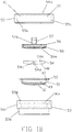
- FIGS. 1B and 3C Such contact to surface 12 by edges 14a and 14b can be assured by a compression member 54 applying uniform pressure upon upper edge 14c the tissue specimen 14 responsive to force applied by a clamp member 56 towards window 10 without damaging tissue edges 14a or 14b, as shown by the exploded view of FIGS. 1B and 3C .
- Window 10 is located at the bottom of a tissue container 51 shown in FIG. 1B .
- Container 51 is a cylinder having an interior sized for receiving compression member 54 and then clamp member 56.
- the container is received in a holder 50 so that the container's flange 52 is received along annular step 50e.
- the upper cylindrical portion 50c of the holder 50 is externally threaded so that a retainer 55 internally threaded along wall 55a can screw onto holder 50 to releasably lock clamp member 56 over compression member 54 and window 10 when tissue specimen 14 is present upon window surface 12.
- Retainer 55 has a central circular opening 55b and two opposing tongues 61.
- clamp member 56 has a knob portion 57 and an annular lip 58 having two opposing slots 59. For purposes of illustration, only one slot is shown in FIG.
- clamp member 56 is inserted into retainer 50 in which slots 59 align with tongues 61 so that the clamp member's annular lip 58 is received along an annular step 60 of container 51.
- clamp member 56 is turned until slots 59 and tongue 59 no longer align with each other, as shown for example in FIG. 3A and 3B as will be described below.
- Lower cylindrical portion 50a of holder 50 is mountable onto stage 20, as will be described in more detail below.
- a releasable locking mechanism is provided to retain clamp member 56 is such position during imaging by objective lens 30 ( FIG. 1A ).
- Window 10 may be attached to container 51 along the container's bottom wall or cover 49 having an opening 49a for receiving the window.
- Window 10 may be rigidly retained to cover 49, such as by adhesive.
- container 51 provides a tissue specimen receptacle having window 10 (or 10a as described later) with substantial surface 12 curvature adapted to at least approximate the surface curvature of an edge or edges of a non-histologically prepared tissue specimen 14 desired to be imaged by an optical sectioning microscope via the window when placed thereupon.
- the assembly of the container 51 with compression member 54 and clamp member 56 is best shown in FIG. 3C .
- Compression member 54 may be made of material which deforms in response to applied pressure, such as Styrofoam.
- the bottom surface 56a of clamp member 56, the top and bottom surfaces 54a and 54b, respectively, of compression member 54 are of the same curvature as the curvature of window surface 12 to facilitate applying uniform pressure towards window 10.
- Compression member 54 thus is located between the bottom of clamp member 56 and window 10, such that compression member 54 gently compresses while applying pressure upon the tissue specimen 14 against window 10.
- the compression member 54 may contact areas of the window around the tissue specimen 12.
- the window 10 of the present invention solves the problem with optical imaging of a tissue specimen for Mohs surgery in that the tissue specimen is generally thick, for example 2-3 mm, to enable optically imaging of all edges of interest along tissue edges 14a and 14b if such tissue specimen 14 was present on a planar window rather than window 10 of the present invention.
- FIG. 2 shows an example of the same tissue specimen 14 now on a planer window 16, where tissue edge 14b is non-planar and hence cannot contact surface 17 of window 16 by mere placement upon window 16. Even by applying pressure along the top edge 14c towards window 16 does not readily enable the tissue edges 14b to being planar against surface 17 as needed for proper optical sectional imaging of the tissue specimen through window 16 without additional manipulation of the tissue specimen as described earlier in connection with U.S. Patent No. 6,411,434 .
- This problem is avoided by providing window 10 with a surface curvature 12 following the expected shape of the edges of a tissue specimen of imaging interest.
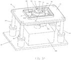
- Stage 20 has a base member (or lower platform) 22 supporting an (upper) platform 23 upon four posts 24.
- Post 24 may be an assembly of one or more shafts for attaching the four corners of platform 23 to base 22 as illustrated.
- Platform 23 has a rectangular opening 26 extending through a carriage mounting plate 23a attached under platform 23 by screws 23b. Extending from platform 23 about opening 26 is an optional wall 27, as shown in FIG. 3A and in cross-section in FIGS. 3B and 3D .
- a carriage 28 is mounted for example to platform 23, via mounting plate 23a, for movement along the two rotational axes described earlier that follow the radius of curvature of surface 12 of window 10. In this manner, different locations along window 10 are presentable to objective lens 30 mounted for example in a tube 30a below carriage 28. However other lens mounting mechanisms may be used.
- objective lens 30 is part of the optics (or optical system) of a confocal microscope head 30b attached to base 22.
- Objective lens 30 may represent an assembly of lens or optical surfaces in tube 30a, and is shown schematically in FIG. 3C as a single lens within tube 30a.
- the last optical surface of lens 30 is denoted at 30c.
- the objective lens 30 is preferably corrected for the base thickness of window 10.
- the gap between window 10 and the last optical surface 30c of objective lens 30 in tube 30a can be filled with an index matching liquid or gel, or may filled with air.
- the particular optics utilized in the objective lens assembly is selected in accordance with the optical material within the gap, the thickness of the window 10 and the curvature of the window 10 to enable optically corrected imaging of the specimen at or near the surface of the window.
- a different objective lens may be utilized for the microscope if the curvature of the window is changed to accommodate different specimen curvatures.
- Confocal microscope head 30b is connected to a computer system (not shown) for providing optical sectional images at different depths in tissue specimen 14 via window 12, which is transparent to the radiation wavelength(s) using in imaging by the microscope. Examples of confocal microscope heads and associated computer system and display are shown in U.S. Patent Nos. 5,788,639 and 7,394,592 , which are incorporated herein by reference.
- head 30b is shown by block 30b.
- Head 30b may also be part of an imaging system for other types of optical sectioning microscopy, such as by two-photon, or optical coherence tomography, Raman microspectroscopy or confocal fluorescence microscopes.
- Carriage 28 comprises two carriage members 29a and 29b orthogonally mounted and moveable (slides) with respect to each other and each travels along a different one of two rotational axes, as described earlier.
- Carriage member 29a has a rectangular opening 62 extending there through, while carriage member 29b has a circular opening 47 receiving tissue container 51 via a holder 50, as described below.
- Carriage member 29a has two first track members 33 attached in ledges along opposite ends 40a and 40b of carriage member 29a.
- Two second track members 35 are attached along opposite ends of rectangular mounting plate 23a, in which each second track members 35 faces one of first track members 33 of carriage member 29a.
- Carriage member 29b has two third track members 42 attached along the underside of the carriage member 29a along opposite ends thereof.
- Carriage member 29a has two fourth track members 44 each facing one of third track members 42 of carriage member 29b.
- Each of the two pairs of first and second track members, and two pairs of third and fourth track members may for example, mated Gonio Way curved cross roller side assemblies, manufactured by Isotech, Inc, of Hatfield PA, USA.
- first track members 33 each have a track, groove, or channel 34 curved following the curvature of the window 10 in the first rotational axis.
- Multiple rotational elements 36 partially extend from each of second track members 35 into track 34 of the first track member 33 facing the second track member 35.
- Rotational elements 36 may be metal balls captured in pockets or openings along second track member 35 enabling rotational mounting of such balls. Such pockets may be formed in a sleeve 37 along each of second track members 35.
- third track members 42 each have a track, groove, or channel 43 curved following the curvature of the window 10 in the second rotational axis.
- Multiple rotational elements 45 partially extend from each of fourth track members 44 into track 43 of the third track member 42 facing the fourth track member 44.
- Rotational elements 45 may be metal balls captured in pockets or openings along track member 44 enabling rotational mounting of such balls. Such pockets may be formed in a sleeve 46 along each of fourth track members 44.
- Circular opening 47 of carriage member 29b receives holder 50 for specimen container 51, as described earlier.
- Holder 50 is a cylinder with a lower cylindrical portion 50a and an upper cylindrical portion 50c.
- Lower cylindrical portion 50a has an outer diameter sized to be received in circular opening 47 so that an upper portion 50c extends away from opening 47, as best shown in FIGS. 1B and 3C .
- the holder 50 may have an outer flange 50b that lies along the top of carriage member 29b around opening 47, or 50b may be a ring clamp.
- opening 47 may have threads and holder 50 may screw into carriage member 29b via a threaded outer lower cylindrical portion 50a.
- holder 50 may be fixed by other means, such a welded or adhesive.
- Upper portion 50c of holder 50 has an opening 50d for receiving tissue container 51 so that an outer flange 52 of container 51 is located along an annular step about opening 50d of upper portion 50c.
- container 51 preferably has exterior threads which enable container 51 to be tightened into threads along interior surface of specimen holder 50 via opening 50d. This enables container 51 to be easily inserted or removed from stage 26, as needed, with or without a tissue specimen being clamped against window 10 via compression member 54.
- a fluid matched to the index of refraction of the tissue surfaces along edges 14a and 14b is preferably provided upon window surface 12 prior to placing the tissue specimen in container 51.
- a hole or bore 56b extends through clamp member 56.
- Clamp member 56 is clamped by retainer 55 against window 10 via compression member 54. Air and/or liquid is allowed to escape, via a bore or hole 54c via its' concave middle opening 54d which communicates such and/or liquid via with bore or hole 56b of clamp member 56 so as to not trap air bubbles with the tissue specimen 10 and give uneven compression. Also, the compression member's concave middle opening 54d provides a relief of pressure upon the middle of the tissue specimen 14 so that pressure is directed more towards tissue specimen edges 14b where it is needed more.
- Tube 30a with objective lens 30 is disposed with respect to carriage 28 to extend through openings 47 and 62, of respective carriage members 29b and 29a, into the interior of lower cylindrical portion 50a of holder 50 to view tissue specimen 14 via window 10 when container 51 is screwed into holder 50.
- Objective lens 30 is directed toward window 10 being carried upon carriage 28 along optical axis 31, as described earlier.
- Carriage 28 may be rotationally tilted following the curvature of window surface 12, as shown for example in FIG. 3C (see angle between arrows 11a with respect to optical axis 31), so that any location of the tissue specimen 14 in contact with window surface 12 can be imaged via objective lens 30 while maintaining the same optical geometry.
- the distance or gap along optical axis 31 may be varied by the confocal microscope along a z axis, via a motor not shown, towards or away from window 10 for focusing at different depths in tissue specimen 14 upon window 10, as typical of a confocal microscope.
- a fluid matched to the index of refraction of the tissue surfaces 14a and 14b is preferably provided upon window surface 12 prior to imaging the tissue specimen 14 through window 10. Selection of the index of refraction fluid may be as described in U.S. Patent No. 6,856,458 .
- piezoelectric motors 38a and 38b are provided.
- Motor 38a is attached to carriage member 29a having an actuator member 64 against member 35 so at to move carriage member 29b with respect to carriage member 29a along first rotational dimension.
- Motor 38b is attached to carriage member 29a having an actuator member 66 against member 42 so at to move carriage member 29a with respect to carriage member 29b along the second rotational dimension.
- piezoelectric motors 38a and 38b may each be Piezo LEGS® Motor of Micromo, Inc. which utilize a walking drive to provide actuator members 64 and 66, respectively, or a PILine® Ultrasonic Piezo Motor manufactured by OEM Motors, having a guide rod to provide actuator members 64 and 66, respectively.
- carriage 28 movement is enabled without motors 38a and 38b by providing a coupler 69 fixed to carriage member 29a in which movement of the coupler along the x, y orthogonal axes correspond to orthogonal axes along with carriage members 29a and 29b.
- Carriage members 29a and 29b move when the carriage members move along their respective rotational axes.
- Coupler 68 has a socket into which is received a ball extending from another coupler 68 where the ball is rotatable in the socket, as typical of ball and socket rotational mounting.
- Coupler 68 has two mounting holes 70 extending there through.
- coupler 69 has a ball received into a socket of coupler 68.
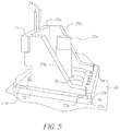
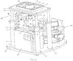
- FIGS. 5 and 6 shows a x-y translation mechanism or stage 72 having a plate 72a movable along the x-axis, and a plate 72b movable along the y axis, in which platform 23 and posts 24 are shown removed in FIG. 5 and present in FIG. 6 .
- Two linear guides and/or tracks 73a along the x axis enable movement of plate 72a along a stationary support plate 71, while two linear guides and/or tracks 73b between plates 72a and 72b enable movement of plate 72b with respect to plate 72a.
- Motors 77a and 77b drive plates 72a and 72b bidirectionally along their respective axes.
- Objective lens 30 with tube 30a extends from microscope head 30b through an opening 76 of stage 72 and is fixed in position with respect to stage 72.
- Attached to plate 72b is a structure 75 having two vertical rods 74 which extend through two holes 70 of coupler 68 as shown in FIG. 5 .
- Structure 75 is provided by two flanges 75a and 75b ( FIG. 5 ) extending from an plate 72b which are connected by a horizontal member 75c into which vertical rods 74 are fixed. Movement of the x-y translation mechanism 72 along the x-axis in x direction effects movement of carriage member 29a and along the y-axis in y direction effects movement of carriage member 29a along their respective rotational axes as shows by arrows labeled X and Y in FIG.
- Coupler 68 is rotationally mounted so that it rotationally pivots with respect to rods 74 as motion is applied by translation mechanism 72 via rods 74 (and couplers 68 and 69) to stage 28.
- Electronics 30d of the microscope is also shown in FIG. 6 .
- Window 10 is rotationally movable, via carriage 28 with respect to platform 23, along two rotational axes utilizing piezoelectric motors 38a and 38b, or motors 77a and 77b, which operate responsive to applied signal(s), such as provided by the computer system of the microscope to enable a user utilizing controls (microscope user interface, such as keyboard, touch screen, GUI, mouse or other pointing device) to select different locations along tissue specimen to obtain optical sectional images thereof.
- Microscope user interface such as keyboard, touch screen, GUI, mouse or other pointing device
- Cells and tissue structure(s) of optical sectional images captured may be viewed by a pathologist to determine whether tissue along tissue specimen surfaces 14a and 14b (tissue margins) at selected locations are cancerous or not so as to direct additional removal of tissue from the patient, if needed.
- window 10 provides a curved pocket for a tissue specimen 14 (see e.g., FIG 1A ).
- window may have other curvatures each shaped for the particular curvature of tissue specimen edges of interest for pathological examination such as shown for example in FIGS. 7A and 7B .
- FIGS. 7A and 7B are similar to FIG. 3C , but have an aspheric window 10a shown in two different rotational positions of carriage 28 and window 10a with respect to the objective lens 30.
- window 10a has an aspheric surface curvature, in which two or more regions or parts of the window may have different radius of curvature.
- the axes of rotation of carriage 28 correspond to radius of region 9b.
- the aspheric window 10a adjusts for the stepper edges of a tissue specimen 14 facing window region 9b, so that such edges readily lie against window 10a when compressed, where such edges are steeper compared with the central area or edges of the tissue specimen.
- Region 9b being steeper so that the edge 14b climbs quicker as window 10a rotates up along region 9b of window 10a, i.e., the radius of window 10a reduces along region 9b from region 9a.
- the user can thus select one of multiple different windows with different surface curvatures (from symmetric to aspheric or different steeped region(s)) in accordance with the shape and size of the tissue cuts along the edges of interest when the tissue specimen is placed in the tissue container assembly of FIG. 1B .
- the optical geometry is adjusted accordingly, i.e., the distance between the objective lens 30 and the window 10a is adjusted to maintain the same optical geometry between the window 10a and the objective lens 30 so that focus is maintained as window 10a moves with respect to objective lens 30.
- This may be achieved by moving objective lens 30 towards or away from window 10a along optical axis 31 as denotes by arrow 30d with window motion.
- the microscope head 30b has a motor which can move the entire tube 30a bidirectionally along axis 31 to maintain focus as regions change.
- each post 24 is adjustable in height along axis 30d.
- Each post 24 may represents two cylinders in which the upper cylinder is slidable through the lower cylinder, and upper cylinder can be pneumatically or by a gear drive motor moved up and down under control of the microscope as needed to control platform 23 height.
- the aspheric (non-spherical) window is especially useful to account for the difference in thickness from the middle to the edge with the radius of curvature changing from the middle out.
- Other windows may also be used, such as spherical or approximately spherical window into which a general spherical tissue specimen is contained and rotated along two rotational axes to image edges against the window.
- Motion of the non-spherical window 10a is controlled such that the window surface adjacent to the tissue specimen is locally perpendicular to the optical axis of the objective lens 30.
- the distance between the window 10a and the objective lens 30 is adjusted so that the image of the section being captured is nominally at the window surface adjacent to the tissue specimen.
- an offset can be added to provide sectional imaging inside the tissue specimen.
Landscapes
- Physics & Mathematics (AREA)
- Chemical & Material Sciences (AREA)
- Analytical Chemistry (AREA)
- General Physics & Mathematics (AREA)
- Optics & Photonics (AREA)
- Microscoopes, Condenser (AREA)
- Sampling And Sample Adjustment (AREA)
Claims (12)
- Gewebeprobentisch (20) für ein Mikroskop mit einer Objektivlinse (30) zur Abbildung von Gewebe (14) durch ein Fenster (10), umfassend:wobei das Fenster (10) eine Oberfläche (12) mit einer Krümmung aufweist, die in zwei Achsen rotationssymmetrisch ist und auf der eine ausgeschnittene Gewebeprobe (14) angeordnet werden kanneinem Schlitten (28), an dem das Fenster (10) befestigt ist; undeine Plattform (23) zum Tragen des Schlittens (28) und zum Präsentieren des Fensters (10) für die Objektivlinse (30) des Mikroskops, wobei der Schlitten (28) an der Plattform (23) für eine Bewegung entlang zweier Rotationsachsen montiert ist, so dass die Schlittenbewegung angepasst ist, um der Krümmung von zumindest einem Teil des Fensters (10) zu folgen, während die optische Geometrie des Fensters (10) in Bezug auf die Objektivlinse (30) beibehalten wird.
- Gewebeprobentisch (20) nach Anspruch 1, wobei die Krümmung der Oberfläche (12) eine Tasche zur Aufnahme der Gewebeprobe (14) bildet.
- Gewebeprobentisch (20) nach Anspruch 1, ferner mit Mitteln zum Bewegen des Schlittens (28) entlang der Rotationsachsen.
- Gewebeprobentisch (20) nach Anspruch 1, ferner umfassend eine Translation (72), die entlang zweier orthogonaler Achsen bewegbar ist, die den beiden Rotationsachsen des Schlittens (28) entsprechen, wobei die Translation (72) mechanisch mit dem Schlitten (28) gekoppelt ist, um eine Bewegung der Translation (72) zu ermöglichen, um den Schlitten (28) entlang einer oder beider der Rotationsachsen zu bewegen.
- Gewebeprobentisch (20) nach Anspruch 1, wobei der Schlitten (28) ferner ein erstes Schlittenelement (29a) und ein zweites Schlittenelement (29b) umfasst, wobei jedes Element (29a, 29b) entlang einer der beiden Rotationsachsen beweglich ist.
- Gewebeprobentisch (20) nach Anspruch 5, wobei das erste Schlittenelement (29a) drehbar an der Plattform (23) für eine Bewegung entlang einer ersten der Rotationsachsen in Bezug auf die Plattform (23) angebracht ist und das zweite Schlittenelement (29b) drehbar an dem ersten Schlittenelement (29a) für eine Bewegung entlang der zweiten der Rotationsachsen angebracht ist.
- Gewebeprobentisch (20) nach Anspruch 6, wobei das erste Schlittenelement (29a) entlang einer ersten der Rotationsachsen in Bezug auf die Plattform (23) motorisch angetrieben ist und das zweite Schlittenelement (29b) entlang der zweiten der Rotationsachsen in Bezug auf das erste Schlittenelement (29a) motorisch angetrieben ist.
- Gewebeprobentisch (20) nach Anspruch 7, ferner umfassend eine Translation (72), die entlang zweier orthogonaler Achsen, die den beiden Rotationsachsen entsprechen, bewegbar ist, wobei die Translation (72) mechanisch mit dem zweiten Schlittenelement (29b) gekoppelt ist, um die Bewegung eines oder beider der ersten und zweiten Schlittenelemente (29a, 29b) entlang ihrer jeweiligen Rotationsachsen zu ermöglichen.
- Ein Gewebeprobenbehälter (51), der Folgendes umfasst:
ein Fenster (10) mit einer Oberfläche mit erheblicher Oberflächenkrümmung, das in zwei Achsen rotationssymmetrisch ist und geeignet ist, zumindest einen Teil der Oberfläche (14a, 14b) einer nicht histologisch präparierten Gewebeprobe (14) abzubilden, wenn es darauf platziert ist, wobei die Gewebeprobe (14) durch das rotationssymmetrisches Fenster (10) durch ein optisches Schnittmikroskop abgebildet wird, mit einer Einrichtung (54), die eine der ersten Fläche gegenüberliegende zweite Fläche aufweist, die der Krümmung der ersten Fläche folgt, und einer Klemmeinrichtung (56) zum Zusammendrücken der Gewebeprobe (14) gegen das rotationssymmetrische Fenster (10), wenn die Gewebeprobe (14) auf dem rotationssymmetrischen Fenster (10) liegt. - Gewebeprobenbehälter (51) nach Anspruch 9, ferner umfassend eine Wand (49) mit einer Öffnung (49a), entlang der das Fenster (10) angeordnet ist.
- Verfahren zum Präsentieren einer exzidierten Gewebeprobe (14) vor einer Objektivlinse (30) eines Mikroskops, um durch ein Fenster (10) abgebildet zu werden, mit den folgenden Schritten:Drehen des Fensters (10), das eine Oberfläche (12) mit einer Krümmung aufweist, die in zwei Achsen rotationssymmetrisch ist, auf der eine exzidierte Gewebeprobe (14) entlang zweier Rotationsachsen angeordnet werden kann, die zumindest einem Teil der genannten der rotationssymmetrischen Krümmung der Oberfläche (12) folgt; undStützen des Fensters (10) in Bezug auf eine Objektivlinse (30) des Mikroskops, wobei der Drehschritt es ermöglicht, die optische Geometrie des Fensters zwischen dem Fenster (10) in Bezug auf die Objektivlinse (30) beizubehalten.
- Eine Vorrichtung zum Präsentieren einer exzidierten Gewebeprobe (14) vor einer Objektivlinse (30) eines Mikroskops, die Folgendes umfasst:ein Fenster (10) mit einer Oberfläche (12) mit einer Krümmung, die in zwei Achsen rotationssymmetrisch ist, auf der eine exzidierte Gewebeprobe (14) platzierbar ist; undeinen Tisch (20) zum Bewegen des Fensters (10) entlang zweier orthogonaler Rotationsachsen, um der rotationssymmetrischen Krümmung zumindest eines Teils des Fensters (10) zu folgen, während die optische Geometrie des Fensters (10) in Bezug auf die Objektivlinse (30) beibehalten wird, wobei die Objektivlinse (30) optisch korrigiert ist, um eine ausgeschnittene Gewebeprobe(14) durch das Fenster (10) abzubilden.
Applications Claiming Priority (2)
| Application Number | Priority Date | Filing Date | Title |
|---|---|---|---|
| US201261603364P | 2012-02-26 | 2012-02-26 | |
| PCT/US2013/027829 WO2013126928A1 (en) | 2012-02-26 | 2013-02-26 | Tissue specimen stage for an optical sectioning microscope |
Publications (3)
| Publication Number | Publication Date |
|---|---|
| EP2817609A1 EP2817609A1 (de) | 2014-12-31 |
| EP2817609A4 EP2817609A4 (de) | 2015-10-28 |
| EP2817609B1 true EP2817609B1 (de) | 2021-04-07 |
Family
ID=49002605
Family Applications (1)
| Application Number | Title | Priority Date | Filing Date |
|---|---|---|---|
| EP13751395.8A Active EP2817609B1 (de) | 2012-02-26 | 2013-02-26 | Gewebeprobentisch für optisches gewebeschnittmikroskop |
Country Status (7)
| Country | Link |
|---|---|
| US (1) | US9229210B2 (de) |
| EP (1) | EP2817609B1 (de) |
| CN (1) | CN104254767B (de) |
| AU (1) | AU2013222070B2 (de) |
| BR (1) | BR112014020937B1 (de) |
| ES (1) | ES2878548T3 (de) |
| WO (1) | WO2013126928A1 (de) |
Families Citing this family (10)
| Publication number | Priority date | Publication date | Assignee | Title |
|---|---|---|---|---|
| WO2016126861A1 (en) * | 2015-02-04 | 2016-08-11 | Apollo Medical Optics Inc. | Optical coherence tomography apparatus and its application |
| JP6841609B2 (ja) | 2015-07-10 | 2021-03-10 | 3スキャン インコーポレイテッド | 組織学的染色の空間的多重化 |
| US10514532B1 (en) | 2015-09-27 | 2019-12-24 | Caliber Imaging & Diagnostics, Inc. | Confocal microscope having a positionable imaging head mounted on a boom stand |
| CN110268299A (zh) | 2016-11-12 | 2019-09-20 | 凯利博成像和诊断公司 | 带有可定位成像头的共焦显微镜 |
| DE102017214189A1 (de) * | 2017-08-15 | 2019-02-21 | Carl Zeiss Microscopy Gmbh | Verfahren zum Betrieb einer Mikroskopieranordnung und Mikroskopieranordnung mit einem ersten Mikroskop und mindestens einem weiteren Mikroskop |
| US11280990B2 (en) | 2018-02-26 | 2022-03-22 | Caliber Imaging & Diagnostics, Inc. | System and method for macroscopic and microscopic imaging ex-vivo tissue |
| EP3956711A4 (de) * | 2019-04-18 | 2023-01-11 | The Administrators of The Tulane Educational Fund | Systeme und verfahren zur probenpositionierung zur erleichterung der mikroskopie |
| CN114695039B (zh) * | 2020-12-28 | 2025-05-09 | 生物岛实验室 | 一种显微镜样品台 |
| DE102021112720A1 (de) * | 2021-05-17 | 2022-11-17 | Physik Instrumente (PI) GmbH & Co KG | 2-dimensional bewegbarer Linear- oder Rotationstisch |
| CN116027537B (zh) * | 2022-10-12 | 2024-10-15 | 西南大学 | 激光共聚焦显微镜生物被膜观察载物台 |
Citations (2)
| Publication number | Priority date | Publication date | Assignee | Title |
|---|---|---|---|---|
| US3220300A (en) * | 1961-06-09 | 1965-11-30 | California Inst Res Found | Specimen holder |
| US20120281208A1 (en) * | 2009-07-21 | 2012-11-08 | National University Corp. Okayama University | Chamber for optical observation, method for optically observing sample, and method for manufacturing lower transparent plate |
Family Cites Families (82)
| Publication number | Priority date | Publication date | Assignee | Title |
|---|---|---|---|---|
| US1002910A (en) | 1911-01-21 | 1911-09-12 | Foote Mineral Co | Display-mount. |
| US1991983A (en) | 1932-08-25 | 1935-02-19 | Joseph S Newman | Microscope slide |
| US2942520A (en) | 1955-12-20 | 1960-06-28 | George G Rose | Tissue culture device |
| US3202049A (en) | 1961-11-29 | 1965-08-24 | Bausch & Lomb | Liquid dispenser for microscope objective |
| US3510194A (en) | 1965-08-09 | 1970-05-05 | Robert F Connelly | Particle count membrane filter mount |
| DE1472294A1 (de) | 1966-09-07 | 1969-02-13 | Leitz Ernst Gmbh | Immersionskoerper |
| GB1242527A (en) | 1967-10-20 | 1971-08-11 | Kodak Ltd | Optical instruments |
| US3551023A (en) | 1969-01-17 | 1970-12-29 | Ibm | Pathology specimen processing method and article |
| US3532412A (en) | 1969-01-17 | 1970-10-06 | Ibm | Package for and method of packaging pathology specimens |
| US3556633A (en) | 1969-01-17 | 1971-01-19 | Winifred Liu Mutschmann | Specimen carrying slide with runoff trough |
| US3736042A (en) | 1971-05-05 | 1973-05-29 | Clinical Sciences Inc | Microscope slide assembly |
| US3879106A (en) | 1973-04-11 | 1975-04-22 | Pelam Inc | Microscope slide cover slip |
| US3904781A (en) | 1973-10-15 | 1975-09-09 | Donald E Henry | Method of preparing cells for inspection |
| US4159875A (en) | 1976-10-21 | 1979-07-03 | Abbott Laboratories | Specimen holder |
| DE2655041C2 (de) | 1976-12-04 | 1982-04-15 | Fa. Carl Zeiss, 7920 Heidenheim | Immersionsobjektiv zum Gebrauch mit mehreren optisch verschiedenen Immersionsmitteln |
| US4545831A (en) | 1982-09-13 | 1985-10-08 | The Mount Sinai School Of Medicine | Method for transferring a thin tissue section |
| DE3323742A1 (de) | 1983-07-01 | 1985-01-10 | Jürgen Dr. med. dent. 3008 Garbsen Kielmann | Makro-dokumentations- und experimentierkammer fuer hartgewebsbiopsien in der medizin und biologie |
| SE455736B (sv) | 1984-03-15 | 1988-08-01 | Sarastro Ab | Forfaringssett och anordning for mikrofotometrering och efterfoljande bildsammanstellning |
| US4752347A (en) | 1986-10-03 | 1988-06-21 | Rada David C | Apparatus for preparing tissue sections |
| US4744643A (en) | 1987-01-20 | 1988-05-17 | Taylor Howard L | Apparatus for restricting motion of living microscopic organisms during observation under a microscope |
| CN87214469U (zh) * | 1987-10-14 | 1988-07-20 | 上海钢铁研究所 | 扫描电子显微镜多功能加载样品台 |
| FR2626383B1 (fr) | 1988-01-27 | 1991-10-25 | Commissariat Energie Atomique | Procede de microscopie optique confocale a balayage et en profondeur de champ etendue et dispositifs pour la mise en oeuvre du procede |
| US4974952A (en) | 1988-03-31 | 1990-12-04 | Focht Daniel C | Live cell chamber for microscopes |
| US5257128A (en) | 1988-06-22 | 1993-10-26 | Board Of Regents, The University Of Texas System | Freezing/perfusion microscope stage |
| US5002735A (en) | 1988-07-12 | 1991-03-26 | Mark T. Alberhasky | Tissue analysis device |
| EP1245987B1 (de) | 1988-07-13 | 2008-01-23 | Optiscan Pty Ltd | Konfokales Rastermikroskop |
| US5073857A (en) | 1989-06-01 | 1991-12-17 | Accuron Corporation | Method and apparatus for cell analysis |
| US5034613A (en) | 1989-11-14 | 1991-07-23 | Cornell Research Foundation, Inc. | Two-photon laser microscopy |
| US5156150A (en) | 1990-06-08 | 1992-10-20 | Lary Banning G | Method of use of specimen apparatus |
| US5076680A (en) | 1990-07-05 | 1991-12-31 | Narong Arjarasumpun | Biological specimen holder for microscopic examination |
| DE4030699C1 (de) | 1990-09-28 | 1991-10-10 | Bruker Analytische Messtechnik Gmbh, 7512 Rheinstetten, De | |
| US5103338A (en) | 1990-10-04 | 1992-04-07 | Crowley Kevin D | Apparatus for positioning objects for microscopic examination |
| US5367401A (en) | 1990-11-23 | 1994-11-22 | Perceptive Scientific Instruments, Inc. | Microscope slide rotary stage |
| EP0501688A1 (de) | 1991-02-27 | 1992-09-02 | Hitachi, Ltd. | Apparat und Methode zur Einspiegelung eines Laserstrahls in einen Mikroskopstrahlengang |
| US5719700A (en) | 1991-10-11 | 1998-02-17 | L'oreal | Apparatus for in vivo observation of the microscopic structure of the skin or of a similar tissue |
| US5311358A (en) | 1992-10-08 | 1994-05-10 | Time Surgical, Inc. | Universal microscope drape |
| US5889881A (en) | 1992-10-14 | 1999-03-30 | Oncometrics Imaging Corp. | Method and apparatus for automatically detecting malignancy-associated changes |
| GB2273994A (en) | 1992-12-18 | 1994-07-06 | Morphometrix Inc | Process microscopy system |
| US5364790A (en) | 1993-02-16 | 1994-11-15 | The Perkin-Elmer Corporation | In situ PCR amplification system |
| US5383472A (en) | 1993-07-22 | 1995-01-24 | Devlin; Mark T. | Method and apparatus for handling of biopsy tissue specimen |
| US5383234A (en) | 1993-09-03 | 1995-01-17 | Beekley Corporation | Radiographic system and a method for using the system for radiographic examination of tissue specimens |
| AU7839294A (en) | 1993-09-22 | 1995-04-10 | Pierce Chemical Company | Device and method for dialyzing samples |
| DE4423935C2 (de) | 1994-07-07 | 1998-02-05 | Deutsche Forsch Luft Raumfahrt | Küvette zur mikroskopischen oder makroskopischen Beobachtung einer biologischen Probe |
| US5554151A (en) | 1994-09-27 | 1996-09-10 | United States Surgical Corporation | Specimen retrieval container |
| US5880880A (en) | 1995-01-13 | 1999-03-09 | The General Hospital Corp. | Three-dimensional scanning confocal laser microscope |
| US5609827A (en) | 1995-05-02 | 1997-03-11 | Beekley Corporation | Biopsy specimen container |
| US5788639A (en) | 1995-07-13 | 1998-08-04 | Lucid Technologies, Inc. | Confocal imaging through thick dermal tissue |
| US7047064B1 (en) | 1995-07-13 | 2006-05-16 | Lucid, Inc. | Microscopic imaging apparatus and method |
| US5939251A (en) | 1996-07-12 | 1999-08-17 | Hu; Min | Apparatus and method for simplifying the processes in creating a sealed space on slides to conduct molecular biological reactions therein |
| US5870223A (en) | 1996-07-22 | 1999-02-09 | Nikon Corporation | Microscope system for liquid immersion observation |
| US6272235B1 (en) | 1997-03-03 | 2001-08-07 | Bacus Research Laboratories, Inc. | Method and apparatus for creating a virtual microscope slide |
| US6424852B1 (en) | 1996-10-18 | 2002-07-23 | Lucid, Inc. | System for confocal imaging within dermal tissue |
| US6745067B1 (en) | 1998-09-14 | 2004-06-01 | Lucid, Inc. | System for marking the locations of imaged tissue with respect to the surface of the tissue |
| US5836877A (en) | 1997-02-24 | 1998-11-17 | Lucid Inc | System for facilitating pathological examination of a lesion in tissue |
| ES2313745T3 (es) | 1997-03-19 | 2009-03-01 | Lucid, Inc. | Cirugia celular que utiliza microscopia confocal. |
| US6100051A (en) | 1997-06-27 | 2000-08-08 | The United States Of America As Represented By The Department Of Health And Human Services | Method utilizing convex geometry for laser capture microdissection |
| US5978695A (en) | 1997-08-18 | 1999-11-02 | Lucid Inc. | System for imaging mechanically stabilized tissue |
| US5812312A (en) | 1997-09-04 | 1998-09-22 | Lorincz; Andrew Endre | Microscope slide |
| US6134010A (en) | 1997-11-07 | 2000-10-17 | Lucid, Inc. | Imaging system using polarization effects to enhance image quality |
| US6048723A (en) | 1997-12-02 | 2000-04-11 | Flexcell International Corporation | Flexible bottom culture plate for applying mechanical load to cell cultures |
| WO1999043994A1 (en) | 1998-02-26 | 1999-09-02 | Lucid, Inc. | Confocal microscope for facilitating cryosurgery of tissue |
| US6358475B1 (en) | 1998-05-27 | 2002-03-19 | Becton, Dickinson And Company | Device for preparing thin liquid for microscopic analysis |
| US6151127A (en) | 1998-05-28 | 2000-11-21 | The General Hospital Corporation | Confocal microscopy |
| AU5920899A (en) | 1998-09-14 | 2000-04-03 | Lucid, Inc. | Imaging of surgical biopsies |
| US7227630B1 (en) | 1998-09-14 | 2007-06-05 | Lucid, Inc. | Imaging of surgical biopsies |
| IL142338A0 (en) * | 1998-09-30 | 2002-03-10 | Trellis Bioinformatics Inc | High throughput microscopy |
| ES2520140T3 (es) | 1999-02-17 | 2014-11-11 | Lucid, Inc. | Portador de muestras de tejido |
| WO2000049392A1 (en) | 1999-02-17 | 2000-08-24 | Lucid, Inc. | Cassette for facilitating optical sectioning of a retained tissue specimen |
| US6720547B1 (en) | 1999-03-18 | 2004-04-13 | Lucid, Inc. | System and method for enhancing confocal reflectance images of tissue specimens |
| US6252705B1 (en) * | 1999-05-25 | 2001-06-26 | Schlumberger Technologies, Inc. | Stage for charged particle microscopy system |
| US7194118B1 (en) | 2000-11-10 | 2007-03-20 | Lucid, Inc. | System for optically sectioning and mapping surgically excised tissue |
| GB0219642D0 (en) | 2002-08-23 | 2002-10-02 | Gauthier Pierre | Method and device for preparing tissues sections |
| CN1791822A (zh) | 2003-05-20 | 2006-06-21 | 卢西德有限公司 | 用于对患者身体所选位置进行成像的共焦显微镜 |
| US20090286305A1 (en) * | 2005-04-15 | 2009-11-19 | Wei-Sing Chu | Method for non-destructive macromolecule extraction from biological samples on slide |
| EP1940286A1 (de) * | 2005-09-29 | 2008-07-09 | General Hospital Corporation | Verfahren und gerät für ein verfahren zur betrachtung und auswertung einer oder mehrerer biologischen proben mit progressiv zunehmender auflösung |
| US7864996B2 (en) | 2006-02-17 | 2011-01-04 | Lucid, Inc. | System for macroscopic and confocal imaging of tissue |
| WO2008084246A1 (en) | 2007-01-11 | 2008-07-17 | Renishaw Plc | A sample positioning apparatus |
| US7835013B2 (en) | 2007-05-18 | 2010-11-16 | Vanderbilt University | Interferometric detection system and method |
| US7869027B2 (en) * | 2009-04-20 | 2011-01-11 | Araca, Inc. | Confocal microscopy pad sample holder that measures displacement and method of using the same |
| CN201465986U (zh) * | 2009-08-04 | 2010-05-12 | 山东理工大学 | 块状金属材料扫描电镜样品台 |
| EP2565663B1 (de) * | 2010-02-01 | 2016-12-14 | Clear-Cut Medical Ltd | Margenbeurteilung einer ex-vivo-tumorprobe |
| CN201732097U (zh) * | 2010-06-22 | 2011-02-02 | 山东建筑大学 | 一种扫描电子显微镜用具有弯曲功能的样品台 |
-
2013
- 2013-02-26 EP EP13751395.8A patent/EP2817609B1/de active Active
- 2013-02-26 WO PCT/US2013/027829 patent/WO2013126928A1/en not_active Ceased
- 2013-02-26 AU AU2013222070A patent/AU2013222070B2/en active Active
- 2013-02-26 US US13/778,083 patent/US9229210B2/en active Active
- 2013-02-26 ES ES13751395T patent/ES2878548T3/es active Active
- 2013-02-26 BR BR112014020937-5A patent/BR112014020937B1/pt active IP Right Grant
- 2013-02-26 CN CN201380019488.6A patent/CN104254767B/zh active Active
Patent Citations (2)
| Publication number | Priority date | Publication date | Assignee | Title |
|---|---|---|---|---|
| US3220300A (en) * | 1961-06-09 | 1965-11-30 | California Inst Res Found | Specimen holder |
| US20120281208A1 (en) * | 2009-07-21 | 2012-11-08 | National University Corp. Okayama University | Chamber for optical observation, method for optically observing sample, and method for manufacturing lower transparent plate |
Also Published As
| Publication number | Publication date |
|---|---|
| AU2013222070A1 (en) | 2014-09-18 |
| US20130222899A1 (en) | 2013-08-29 |
| ES2878548T3 (es) | 2021-11-19 |
| AU2013222070B2 (en) | 2016-07-07 |
| CN104254767A (zh) | 2014-12-31 |
| EP2817609A1 (de) | 2014-12-31 |
| CN104254767B (zh) | 2016-10-26 |
| BR112014020937B1 (pt) | 2021-11-09 |
| US9229210B2 (en) | 2016-01-05 |
| WO2013126928A1 (en) | 2013-08-29 |
| EP2817609A4 (de) | 2015-10-28 |
| BR112014020937A2 (pt) | 2021-07-20 |
Similar Documents
| Publication | Publication Date | Title |
|---|---|---|
| EP2817609B1 (de) | Gewebeprobentisch für optisches gewebeschnittmikroskop | |
| US20240044805A1 (en) | Systems and methods for in-operating-theatre imaging of fresh tissue resected during surgery for pathology assessment | |
| US10409052B2 (en) | Inverted light-sheet microscope | |
| US20110224574A1 (en) | Methods and systems for tissue processing and imaging | |
| US20190302439A1 (en) | Selective plane illumination microscopy with multiple illumination units scanning an object in sync with a digital camera rolling shutter | |
| CN110268299A (zh) | 带有可定位成像头的共焦显微镜 | |
| CN103479331A (zh) | 用于经由谱编码进行光学成像的方法和设备 | |
| EP1121052B1 (de) | Bildgebung von chirurgischen biopsien | |
| CN112136071A (zh) | 用于对体外组织进行宏观和微观成像的系统和方法 | |
| EP2883031B1 (de) | Vorrichtungen zur anwendung auf gewebe mit der möglichkeit von konfokalmikroskopie, optischer mikroskopie, spektroskopie und/oder bildgebung | |
| KR101840081B1 (ko) | 세포학적 표본 준비장치 | |
| EP3553583A1 (de) | Mikroskopie mit beleuchtung selektiver ebenen mit mehreren beleuchtungseinheiten zur synchronen abtastung eines objekts mit einer rollblende einer digitalen kamera | |
| US11906720B1 (en) | Devices for ex vivo microscopic analysis of samples and in vivo microscopic analysis of the skin | |
| US20190227054A1 (en) | System, method and computer readable medium for microscopic imaging |
Legal Events
| Date | Code | Title | Description |
|---|---|---|---|
| PUAI | Public reference made under article 153(3) epc to a published international application that has entered the european phase |
Free format text: ORIGINAL CODE: 0009012 |
|
| 17P | Request for examination filed |
Effective date: 20140826 |
|
| AK | Designated contracting states |
Kind code of ref document: A1 Designated state(s): AL AT BE BG CH CY CZ DE DK EE ES FI FR GB GR HR HU IE IS IT LI LT LU LV MC MK MT NL NO PL PT RO RS SE SI SK SM TR |
|
| AX | Request for extension of the european patent |
Extension state: BA ME |
|
| DAX | Request for extension of the european patent (deleted) | ||
| RA4 | Supplementary search report drawn up and despatched (corrected) |
Effective date: 20150924 |
|
| RIC1 | Information provided on ipc code assigned before grant |
Ipc: G01N 21/00 20060101AFI20150918BHEP |
|
| STAA | Information on the status of an ep patent application or granted ep patent |
Free format text: STATUS: EXAMINATION IS IN PROGRESS |
|
| 17Q | First examination report despatched |
Effective date: 20191111 |
|
| REG | Reference to a national code |
Ref country code: DE Ref legal event code: R079 Ref document number: 602013076739 Country of ref document: DE Free format text: PREVIOUS MAIN CLASS: G01N0021000000 Ipc: G02B0021260000 |
|
| RIC1 | Information provided on ipc code assigned before grant |
Ipc: G02B 21/26 20060101AFI20201228BHEP Ipc: G02B 21/34 20060101ALN20201228BHEP |
|
| GRAP | Despatch of communication of intention to grant a patent |
Free format text: ORIGINAL CODE: EPIDOSNIGR1 |
|
| STAA | Information on the status of an ep patent application or granted ep patent |
Free format text: STATUS: GRANT OF PATENT IS INTENDED |
|
| GRAS | Grant fee paid |
Free format text: ORIGINAL CODE: EPIDOSNIGR3 |
|
| GRAA | (expected) grant |
Free format text: ORIGINAL CODE: 0009210 |
|
| STAA | Information on the status of an ep patent application or granted ep patent |
Free format text: STATUS: THE PATENT HAS BEEN GRANTED |
|
| INTG | Intention to grant announced |
Effective date: 20210209 |
|
| AK | Designated contracting states |
Kind code of ref document: B1 Designated state(s): AL AT BE BG CH CY CZ DE DK EE ES FI FR GB GR HR HU IE IS IT LI LT LU LV MC MK MT NL NO PL PT RO RS SE SI SK SM TR |
|
| REG | Reference to a national code |
Ref country code: GB Ref legal event code: FG4D |
|
| REG | Reference to a national code |
Ref country code: AT Ref legal event code: REF Ref document number: 1380439 Country of ref document: AT Kind code of ref document: T Effective date: 20210415 Ref country code: CH Ref legal event code: EP |
|
| REG | Reference to a national code |
Ref country code: DE Ref legal event code: R096 Ref document number: 602013076739 Country of ref document: DE |
|
| REG | Reference to a national code |
Ref country code: IE Ref legal event code: FG4D |
|
| REG | Reference to a national code |
Ref country code: LT Ref legal event code: MG9D |
|
| REG | Reference to a national code |
Ref country code: NL Ref legal event code: MP Effective date: 20210407 Ref country code: AT Ref legal event code: MK05 Ref document number: 1380439 Country of ref document: AT Kind code of ref document: T Effective date: 20210407 |
|
| PG25 | Lapsed in a contracting state [announced via postgrant information from national office to epo] |
Ref country code: NL Free format text: LAPSE BECAUSE OF FAILURE TO SUBMIT A TRANSLATION OF THE DESCRIPTION OR TO PAY THE FEE WITHIN THE PRESCRIBED TIME-LIMIT Effective date: 20210407 Ref country code: LT Free format text: LAPSE BECAUSE OF FAILURE TO SUBMIT A TRANSLATION OF THE DESCRIPTION OR TO PAY THE FEE WITHIN THE PRESCRIBED TIME-LIMIT Effective date: 20210407 Ref country code: FI Free format text: LAPSE BECAUSE OF FAILURE TO SUBMIT A TRANSLATION OF THE DESCRIPTION OR TO PAY THE FEE WITHIN THE PRESCRIBED TIME-LIMIT Effective date: 20210407 Ref country code: HR Free format text: LAPSE BECAUSE OF FAILURE TO SUBMIT A TRANSLATION OF THE DESCRIPTION OR TO PAY THE FEE WITHIN THE PRESCRIBED TIME-LIMIT Effective date: 20210407 Ref country code: BG Free format text: LAPSE BECAUSE OF FAILURE TO SUBMIT A TRANSLATION OF THE DESCRIPTION OR TO PAY THE FEE WITHIN THE PRESCRIBED TIME-LIMIT Effective date: 20210707 Ref country code: AT Free format text: LAPSE BECAUSE OF FAILURE TO SUBMIT A TRANSLATION OF THE DESCRIPTION OR TO PAY THE FEE WITHIN THE PRESCRIBED TIME-LIMIT Effective date: 20210407 |
|
| REG | Reference to a national code |
Ref country code: ES Ref legal event code: FG2A Ref document number: 2878548 Country of ref document: ES Kind code of ref document: T3 Effective date: 20211119 |
|
| PG25 | Lapsed in a contracting state [announced via postgrant information from national office to epo] |
Ref country code: RS Free format text: LAPSE BECAUSE OF FAILURE TO SUBMIT A TRANSLATION OF THE DESCRIPTION OR TO PAY THE FEE WITHIN THE PRESCRIBED TIME-LIMIT Effective date: 20210407 Ref country code: SE Free format text: LAPSE BECAUSE OF FAILURE TO SUBMIT A TRANSLATION OF THE DESCRIPTION OR TO PAY THE FEE WITHIN THE PRESCRIBED TIME-LIMIT Effective date: 20210407 Ref country code: PL Free format text: LAPSE BECAUSE OF FAILURE TO SUBMIT A TRANSLATION OF THE DESCRIPTION OR TO PAY THE FEE WITHIN THE PRESCRIBED TIME-LIMIT Effective date: 20210407 Ref country code: NO Free format text: LAPSE BECAUSE OF FAILURE TO SUBMIT A TRANSLATION OF THE DESCRIPTION OR TO PAY THE FEE WITHIN THE PRESCRIBED TIME-LIMIT Effective date: 20210707 Ref country code: PT Free format text: LAPSE BECAUSE OF FAILURE TO SUBMIT A TRANSLATION OF THE DESCRIPTION OR TO PAY THE FEE WITHIN THE PRESCRIBED TIME-LIMIT Effective date: 20210809 Ref country code: LV Free format text: LAPSE BECAUSE OF FAILURE TO SUBMIT A TRANSLATION OF THE DESCRIPTION OR TO PAY THE FEE WITHIN THE PRESCRIBED TIME-LIMIT Effective date: 20210407 Ref country code: GR Free format text: LAPSE BECAUSE OF FAILURE TO SUBMIT A TRANSLATION OF THE DESCRIPTION OR TO PAY THE FEE WITHIN THE PRESCRIBED TIME-LIMIT Effective date: 20210708 Ref country code: IS Free format text: LAPSE BECAUSE OF FAILURE TO SUBMIT A TRANSLATION OF THE DESCRIPTION OR TO PAY THE FEE WITHIN THE PRESCRIBED TIME-LIMIT Effective date: 20210807 |
|
| REG | Reference to a national code |
Ref country code: DE Ref legal event code: R097 Ref document number: 602013076739 Country of ref document: DE |
|
| PG25 | Lapsed in a contracting state [announced via postgrant information from national office to epo] |
Ref country code: RO Free format text: LAPSE BECAUSE OF FAILURE TO SUBMIT A TRANSLATION OF THE DESCRIPTION OR TO PAY THE FEE WITHIN THE PRESCRIBED TIME-LIMIT Effective date: 20210407 Ref country code: CZ Free format text: LAPSE BECAUSE OF FAILURE TO SUBMIT A TRANSLATION OF THE DESCRIPTION OR TO PAY THE FEE WITHIN THE PRESCRIBED TIME-LIMIT Effective date: 20210407 Ref country code: EE Free format text: LAPSE BECAUSE OF FAILURE TO SUBMIT A TRANSLATION OF THE DESCRIPTION OR TO PAY THE FEE WITHIN THE PRESCRIBED TIME-LIMIT Effective date: 20210407 Ref country code: DK Free format text: LAPSE BECAUSE OF FAILURE TO SUBMIT A TRANSLATION OF THE DESCRIPTION OR TO PAY THE FEE WITHIN THE PRESCRIBED TIME-LIMIT Effective date: 20210407 Ref country code: SK Free format text: LAPSE BECAUSE OF FAILURE TO SUBMIT A TRANSLATION OF THE DESCRIPTION OR TO PAY THE FEE WITHIN THE PRESCRIBED TIME-LIMIT Effective date: 20210407 Ref country code: SM Free format text: LAPSE BECAUSE OF FAILURE TO SUBMIT A TRANSLATION OF THE DESCRIPTION OR TO PAY THE FEE WITHIN THE PRESCRIBED TIME-LIMIT Effective date: 20210407 |
|
| PLBE | No opposition filed within time limit |
Free format text: ORIGINAL CODE: 0009261 |
|
| STAA | Information on the status of an ep patent application or granted ep patent |
Free format text: STATUS: NO OPPOSITION FILED WITHIN TIME LIMIT |
|
| 26N | No opposition filed |
Effective date: 20220110 |
|
| PG25 | Lapsed in a contracting state [announced via postgrant information from national office to epo] |
Ref country code: IS Free format text: LAPSE BECAUSE OF FAILURE TO SUBMIT A TRANSLATION OF THE DESCRIPTION OR TO PAY THE FEE WITHIN THE PRESCRIBED TIME-LIMIT Effective date: 20210807 Ref country code: AL Free format text: LAPSE BECAUSE OF FAILURE TO SUBMIT A TRANSLATION OF THE DESCRIPTION OR TO PAY THE FEE WITHIN THE PRESCRIBED TIME-LIMIT Effective date: 20210407 |
|
| PG25 | Lapsed in a contracting state [announced via postgrant information from national office to epo] |
Ref country code: MC Free format text: LAPSE BECAUSE OF FAILURE TO SUBMIT A TRANSLATION OF THE DESCRIPTION OR TO PAY THE FEE WITHIN THE PRESCRIBED TIME-LIMIT Effective date: 20210407 |
|
| REG | Reference to a national code |
Ref country code: CH Ref legal event code: PL |
|
| REG | Reference to a national code |
Ref country code: BE Ref legal event code: MM Effective date: 20220228 |
|
| PG25 | Lapsed in a contracting state [announced via postgrant information from national office to epo] |
Ref country code: LU Free format text: LAPSE BECAUSE OF NON-PAYMENT OF DUE FEES Effective date: 20220226 |
|
| PG25 | Lapsed in a contracting state [announced via postgrant information from national office to epo] |
Ref country code: LI Free format text: LAPSE BECAUSE OF NON-PAYMENT OF DUE FEES Effective date: 20220228 Ref country code: IE Free format text: LAPSE BECAUSE OF NON-PAYMENT OF DUE FEES Effective date: 20220226 Ref country code: CH Free format text: LAPSE BECAUSE OF NON-PAYMENT OF DUE FEES Effective date: 20220228 |
|
| PG25 | Lapsed in a contracting state [announced via postgrant information from national office to epo] |
Ref country code: BE Free format text: LAPSE BECAUSE OF NON-PAYMENT OF DUE FEES Effective date: 20220228 |
|
| P01 | Opt-out of the competence of the unified patent court (upc) registered |
Effective date: 20230524 |
|
| PG25 | Lapsed in a contracting state [announced via postgrant information from national office to epo] |
Ref country code: HU Free format text: LAPSE BECAUSE OF FAILURE TO SUBMIT A TRANSLATION OF THE DESCRIPTION OR TO PAY THE FEE WITHIN THE PRESCRIBED TIME-LIMIT; INVALID AB INITIO Effective date: 20130226 |
|
| PG25 | Lapsed in a contracting state [announced via postgrant information from national office to epo] |
Ref country code: MK Free format text: LAPSE BECAUSE OF FAILURE TO SUBMIT A TRANSLATION OF THE DESCRIPTION OR TO PAY THE FEE WITHIN THE PRESCRIBED TIME-LIMIT Effective date: 20210407 Ref country code: CY Free format text: LAPSE BECAUSE OF FAILURE TO SUBMIT A TRANSLATION OF THE DESCRIPTION OR TO PAY THE FEE WITHIN THE PRESCRIBED TIME-LIMIT Effective date: 20210407 |
|
| PG25 | Lapsed in a contracting state [announced via postgrant information from national office to epo] |
Ref country code: TR Free format text: LAPSE BECAUSE OF FAILURE TO SUBMIT A TRANSLATION OF THE DESCRIPTION OR TO PAY THE FEE WITHIN THE PRESCRIBED TIME-LIMIT Effective date: 20210407 |
|
| PG25 | Lapsed in a contracting state [announced via postgrant information from national office to epo] |
Ref country code: MT Free format text: LAPSE BECAUSE OF FAILURE TO SUBMIT A TRANSLATION OF THE DESCRIPTION OR TO PAY THE FEE WITHIN THE PRESCRIBED TIME-LIMIT Effective date: 20210407 |
|
| REG | Reference to a national code |
Ref country code: GB Ref legal event code: 732E Free format text: REGISTERED BETWEEN 20260115 AND 20260121 |
|
| PGFP | Annual fee paid to national office [announced via postgrant information from national office to epo] |
Ref country code: GB Payment date: 20260226 Year of fee payment: 14 |
|
| PGFP | Annual fee paid to national office [announced via postgrant information from national office to epo] |
Ref country code: ES Payment date: 20260303 Year of fee payment: 14 |
|
| PGFP | Annual fee paid to national office [announced via postgrant information from national office to epo] |
Ref country code: DE Payment date: 20260226 Year of fee payment: 14 |
|
| PGFP | Annual fee paid to national office [announced via postgrant information from national office to epo] |
Ref country code: IT Payment date: 20260219 Year of fee payment: 14 |
|
| PGFP | Annual fee paid to national office [announced via postgrant information from national office to epo] |
Ref country code: FR Payment date: 20260227 Year of fee payment: 14 |
|
| REG | Reference to a national code |
Ref country code: GB Ref legal event code: 732E Free format text: REGISTERED BETWEEN 20260326 AND 20260401 |
|
| REG | Reference to a national code |
Ref country code: DE Ref legal event code: R081 Ref document number: 602013076739 Country of ref document: DE Owner name: AURAD GMBH, DE Free format text: FORMER OWNER: CALIBER IMAGING & DIAGNOSTICS INC., ROCHESTER, NY, US |