EP2817675B1 - 3d fotofinish bildanzeiger - Google Patents
3d fotofinish bildanzeiger Download PDFInfo
- Publication number
- EP2817675B1 EP2817675B1 EP13704090.3A EP13704090A EP2817675B1 EP 2817675 B1 EP2817675 B1 EP 2817675B1 EP 13704090 A EP13704090 A EP 13704090A EP 2817675 B1 EP2817675 B1 EP 2817675B1
- Authority
- EP
- European Patent Office
- Prior art keywords
- camera
- image
- finish
- cameras
- finish line
- Prior art date
- Legal status (The legal status is an assumption and is not a legal conclusion. Google has not performed a legal analysis and makes no representation as to the accuracy of the status listed.)
- Active
Links
Images

Classifications
-
- H—ELECTRICITY
- H04—ELECTRIC COMMUNICATION TECHNIQUE
- H04N—PICTORIAL COMMUNICATION, e.g. TELEVISION
- H04N13/00—Stereoscopic video systems; Multi-view video systems; Details thereof
- H04N13/20—Image signal generators
- H04N13/204—Image signal generators using stereoscopic image cameras
- H04N13/243—Image signal generators using stereoscopic image cameras using three or more two-dimensional [2D] image sensors
-
- G—PHYSICS
- G03—PHOTOGRAPHY; CINEMATOGRAPHY; ANALOGOUS TECHNIQUES USING WAVES OTHER THAN OPTICAL WAVES; ELECTROGRAPHY; HOLOGRAPHY
- G03B—APPARATUS OR ARRANGEMENTS FOR TAKING PHOTOGRAPHS OR FOR PROJECTING OR VIEWING THEM; APPARATUS OR ARRANGEMENTS EMPLOYING ANALOGOUS TECHNIQUES USING WAVES OTHER THAN OPTICAL WAVES; ACCESSORIES THEREFOR
- G03B15/00—Special procedures for taking photographs; Apparatus therefor
-
- G—PHYSICS
- G03—PHOTOGRAPHY; CINEMATOGRAPHY; ANALOGOUS TECHNIQUES USING WAVES OTHER THAN OPTICAL WAVES; ELECTROGRAPHY; HOLOGRAPHY
- G03B—APPARATUS OR ARRANGEMENTS FOR TAKING PHOTOGRAPHS OR FOR PROJECTING OR VIEWING THEM; APPARATUS OR ARRANGEMENTS EMPLOYING ANALOGOUS TECHNIQUES USING WAVES OTHER THAN OPTICAL WAVES; ACCESSORIES THEREFOR
- G03B17/00—Details of cameras or camera bodies; Accessories therefor
- G03B17/24—Details of cameras or camera bodies; Accessories therefor with means for separately producing marks on the film, e.g. title, time of exposure
-
- G—PHYSICS
- G03—PHOTOGRAPHY; CINEMATOGRAPHY; ANALOGOUS TECHNIQUES USING WAVES OTHER THAN OPTICAL WAVES; ELECTROGRAPHY; HOLOGRAPHY
- G03B—APPARATUS OR ARRANGEMENTS FOR TAKING PHOTOGRAPHS OR FOR PROJECTING OR VIEWING THEM; APPARATUS OR ARRANGEMENTS EMPLOYING ANALOGOUS TECHNIQUES USING WAVES OTHER THAN OPTICAL WAVES; ACCESSORIES THEREFOR
- G03B35/00—Stereoscopic photography
- G03B35/08—Stereoscopic photography by simultaneous recording
-
- G—PHYSICS
- G03—PHOTOGRAPHY; CINEMATOGRAPHY; ANALOGOUS TECHNIQUES USING WAVES OTHER THAN OPTICAL WAVES; ELECTROGRAPHY; HOLOGRAPHY
- G03B—APPARATUS OR ARRANGEMENTS FOR TAKING PHOTOGRAPHS OR FOR PROJECTING OR VIEWING THEM; APPARATUS OR ARRANGEMENTS EMPLOYING ANALOGOUS TECHNIQUES USING WAVES OTHER THAN OPTICAL WAVES; ACCESSORIES THEREFOR
- G03B41/00—Special techniques not covered by groups G03B31/00 - G03B39/00; Apparatus therefor
-
- G—PHYSICS
- G04—HOROLOGY
- G04F—TIME-INTERVAL MEASURING
- G04F10/00—Apparatus for measuring unknown time intervals by electric means
-
- G—PHYSICS
- G07—CHECKING-DEVICES
- G07C—TIME OR ATTENDANCE REGISTERS; REGISTERING OR INDICATING THE WORKING OF MACHINES; GENERATING RANDOM NUMBERS; VOTING OR LOTTERY APPARATUS; ARRANGEMENTS, SYSTEMS OR APPARATUS FOR CHECKING NOT PROVIDED FOR ELSEWHERE
- G07C1/00—Registering, indicating or recording the time of events or elapsed time, e.g. time-recorders for work people
- G07C1/22—Registering, indicating or recording the time of events or elapsed time, e.g. time-recorders for work people in connection with sports or games
- G07C1/24—Race time-recorders
-
- H—ELECTRICITY
- H04—ELECTRIC COMMUNICATION TECHNIQUE
- H04N—PICTORIAL COMMUNICATION, e.g. TELEVISION
- H04N7/00—Television systems
- H04N7/08—Systems for the simultaneous or sequential transmission of more than one television signal, e.g. additional information signals, the signals occupying wholly or partially the same frequency band, e.g. by time division
- H04N7/0806—Systems for the simultaneous or sequential transmission of more than one television signal, e.g. additional information signals, the signals occupying wholly or partially the same frequency band, e.g. by time division the signals being two or more video signals
-
- H—ELECTRICITY
- H04—ELECTRIC COMMUNICATION TECHNIQUE
- H04N—PICTORIAL COMMUNICATION, e.g. TELEVISION
- H04N7/00—Television systems
- H04N7/18—Closed-circuit television [CCTV] systems, i.e. systems in which the video signal is not broadcast
- H04N7/181—Closed-circuit television [CCTV] systems, i.e. systems in which the video signal is not broadcast for receiving images from a plurality of remote sources
Definitions
- the present invention relates to the display of timed data during a sports competition, and more particularly to a display of type photofinish at a finish line.
- the chronometer In the context of timed sports races, and in particular track and field races, the chronometer is generally triggered synchronously with the emission of an acoustic signal and stopped for each competitor when each crosses the finish line respectively. . It is possible, however, that the resolution of the timing system, for example typically the hundredth of a second, is not sufficient to decide between two competitors whose measured time is identical. To this end, timekeeping devices are required and there are manually operated systems for this purpose which are based on the visual recognition of images taken sequentially by a high definition camera centered very precisely at the line of the camera. 'arrival.
- An operator analyzes, asynchronously after the arrival of the competitors, the sequence of images taken at given times and therefore corresponding to a timed time; this analysis makes it possible to determine a more precise time of crossing the line of each competitor, for example by the thousandth of a second and to classify competitors reliably.
- This type of auxiliary display system for timing is usually called "photofinish".
- auxiliary display system Such a type of auxiliary display system, known for a relatively long time, is described for example in the document US3502009 relating to a dog race.
- the photofinish device makes it possible to superimpose time values, obtained using a first objective centered on a timing device, on images of competitors using a second objective centered on the line of arrival.
- the film thus developed allows to determine the first to cross the line and its time of passage.
- the "photofinish" type systems very often use several cameras.
- none of the cameras used can be shifted sideways to solve this masking problem; this is the reason why the two cameras used are located respectively on both sides of the finish line.
- Stereoscopic optical systems are also known for displaying three-dimensional images, which make it easier and more intuitive for the user to view them.
- These stereoscopic systems are based on the construction of a relief image according to the cerebral scheme, that is to say, from the analysis of two plane images taken along distinct axes of view.
- These stereoscopic systems thus typically use dual lens cameras, the spacing of which for example corresponds to the average interocular space, ie approximately 75 to 80 millimeters.
- these optical systems are unfortunately not suitable for a photofinish type system because of the lateral shift that it assumes between the axes of view, which
- An object of the present invention is to provide a device and a method for displaying 3-dimensional photofinish images.
- Another object of the present invention is to provide such a device and such a method that is simple to implement and inexpensive.
- a system imaging device of the photofinish type comprising a first camera aligned with a finish line, and characterized in that it comprises a second camera also aligned on the finish line and offset from a first height with respect to the first camera for displaying stereoscopic three-dimensional images.
- a first method for the formation of a three-dimensional photofinish image characterized in that it contains the steps of defining a shooting time T, of time synchronization of a first and a second camera, aligned on the finish line and mutually offset by a height h, on a reference time To, of forming a first image by the first camera for this reference time To and forming a second image by the second camera for the same reference time To, and then aggregating these two images to form a stereoscopic type image.
- An advantage of the present invention is to produce a relief-type photofinish image in a simple manner, without the need for complex image processing tools, and which can be easily displayed for spectators present in a sports enclosure or viewers.
- Another advantage of the solution is to provide a modular architecture for the implementation of a system and a stereoscopic display method, requiring little modification compared to the usual existing infrastructure for photofinish type systems.
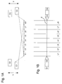
- the Figure 1A shows a front view, in the axis of a finish line, of a plurality of cameras used according to a preferred embodiment of the present invention.
- the stereoscopic images are formed from two images taken at the same reference time by two cameras offset in height relative to one another.
- a first camera C1 and a second camera C2 both aligned on the finish line, are mutually offset by a first height h and similarly and a third camera C3 and fourth camera C4, both aligned on the line of arrival, are mutually offset by a second height h '.
- the advantage of having two pairs of cameras located on either side of the finish line, that is to say to form the pairs C1-C2 and C3-C4, consists in being able to choose the pair of most advantageous camera depending on the position of the various competitors on the finish line to avoid any masking.
- the Figure 1B illustrating the same eight lanes L1-L8 as well as the finish line 0, shows the alignment of the four cameras C1, C2, C3, C4 on this finish line 0 as well as their grouping in pairs C1-C2 and C3 -C4 on both sides of the finish line 0.
- the cameras of each pair are represented with a slight axial shift in order to be able to better distinguish between them.
- the height difference between the cameras of each of the pairs is chosen, for practical reasons, much greater than the spacing interocular to facilitate their installation.
- a first spacing h and a second spacing h ' preferably between 40 and 50 centimeters, in order to allow sufficient space for installation of the 2nd pair the camera when the first has already been positioned, and at the same time be able to correct the multiplicative factor of the distance between the cameras of each pair relative to the average interocular space by zooming effect, that is to say by modifying the focal distance of the camera lens.
- the first spacing h and the second spacing h ' need not be equal, and may be adjusted according to the constraints of the venue where the competition is held, so as not to require any adjustment of the existing infrastructure and thus minimize the constraints congestion of the proposed imaging system.
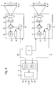
- the figure 2 illustrates a diagram of the imaging device for photofinish system according to a preferred embodiment of the invention, showing in detail the physical architecture of the two cameras C1 and C2, illustrated on the figure 1 B previous, and their interaction with the timing system 6 and the stereoscopic display system 3.
- Each of the two cameras C1 and C2 comprises a lens (referenced respectively 10 and 20 for each camera) at the end of an objective forming the image of a narrow band (referenced respectively 1 and 2 for each camera, and also commonly referred to as "frames") of height H and width 1 via matrix sensors of the LS-CCD type (ie Line-Scan Charge Coupled Device), or CMOS referenced respectively 11 and 21 for each camera C1 and C2, whose size can reach several thousand pixels.
- the objective is preferably set at the finish line to display an image of a predefined height H, which is done using a number N of pixels of the matrix, visible in the figures 3A and 3B below.
- the LS-CCD / CMOS sensor may preferably consist of a matrix of a single column of pixels, so that the width l corresponding of the image bands 1 and 2 is completely determined according to the height H of the image to be displayed and the number N of pixels of the column of this sensor. According to one variant, it is possible to use a matrix CCD / CMOS sensor comprising several columns, of which only one predefined column is used to form the images at the finish line.
- An image sampler controller (referenced respectively 15-25 on each camera C1, C2) detects the brightness levels at each of the LS-CCD / CMOS sensors 11-21 at regular time intervals, and then amplifies the signals. with controlled gain gain amplifiers (referenced respectively 12 and 22 on each of the cameras C1-C2) and converts them in digital form using analog-digital converters (A / D, respectively referenced 13-23 for each of the cameras C1 and C2) and saves them in a memory area (referenced respectively 14-24 for each of the cameras C1 and C2).
- a / D analog-digital converters
- Memory areas also called “buffers" preferably contain several hundred megabytes of RAM, for example SDRAM (synchronous dynamic random access memory) to contain several hours of images.
- each of the cameras C1 and C2 on a relative reference time that is to say with respect to the start of a race, and not just an absolute time, they will each be connected to the system. 6.
- Each of the transmitted pixel columns corresponding to a reference time can be saved with a marker ("flag" in English) corresponding to this reference time and thus allow easier subsequent processing of the data.
- the first camera C1 and the second camera C2 are each connected to an image management system 4, for example a computer server, comprising a processor 41 and a memory unit 42 for processing the data recovered at the output of the memory areas 14-24 cameras C1 and C2 and form a stereoscopic image 30.
- the image management system 4 is also connected to a control screen 5 to allow an operator to view the images before transmitting them via a line transmission 31 for example of the broadcast type, to television receivers (for example via a digital radio network, compliant with the DVB standard) or to a group of computers connected to the Internet via an IP-multicast network.
- the stereoscopic display system 3 illustrated in FIG. figure 2 which includes the image management system 4 and the connection to the transmission line 31, thus makes it possible on the one hand to form a stereoscopic image 30 from the frames received from the cameras C1 and C2, and also to transmit this image for display on remote receivers (not shown in this figure).
- the figures 3 shows a preferred variant of method according to which a stereoscopic image of photofinish type can be generated.
- the method for forming a three-dimensional photofinish image contains a step (A) prior to defining a shooting duration (T), which determines the size of the image that is to be displayed , or more precisely its width L. Indeed, if each image band or frame corresponds to a width /, the sampling frequency, for example every thousandths of a second, as well as the time T of the duration of the capture of view, which is chosen as a multiple of the thousandth, such as for example a second, determines a number of pixels M which conditions the width L of the corresponding image.
- the time axis t extends from right to left from a chosen reference moment To which corresponds to the time of shooting of the rightmost image bands, all the other image bands having been taken after this reference moment.
- the time axis t would extend from left to right, that is to say always in the opposite direction to that of the course of the race.
- the first and second images taken by the first and second cameras C1 and C2 are respectively referenced I1 and I2; they are digitized in the form of a matrix of pixels N * M, corresponding to a height H and a width L.
- the pixel matrix is obtained by aggregation of the different pixel columns 101 and 102 respectively corresponding to the image bands (or frames) 1 and 2.
- each image I1 and I2 of each camera C1 and C2 In order for each image I1 and I2 of each camera C1 and C2 to correspond to the same instant T0, it is necessary to perform a temporal synchronization step (B0) of the first camera C1 and the second camera C2, which are both aligned on the finish line 0, before forming the stereoscopic image 30, because according to this mode of Preferred embodiment each of the images composing the stereoscopic image must correspond to what each eye sees simultaneously.
- this synchronization is performed by connecting each of the cameras to the timing system 6, the first image I1 obtained from said first camera C1 is formed for said reference time To and the second image 12 obtained from the second camera C2 for the reference time To during steps B1 and B2, performed alternately or simultaneously by the image management system 4.
- the axis of the two cameras C1, C2 - and also that of the cameras C3, C4 opposite side of the finish line - is vertical in the plane of the finish line, and it determines the orientation line. eyes perceiving the stereoscopic image.
- the stereoscopic image is formed as if the first camera C1 was the left or right eye, and the second camera C2 was the other eye, which would force a viewer to lean his head 90 degrees to the right or the right.
- an additional image recovery step C will be carried out, consisting for example of C 'unstacking sub-steps and C' matrix transposition when this rectification operation is performed by the system.
- the sub-step of rendering C ' makes it possible to perform a central symmetry by saving all the columns of pixels corresponding to the frames of the images I1 and I2 in LIFO mode (last in first out) in a new image.
- step C 'followed by step C makes it possible to assign virtually a one eye camera and determine the axis of view: step C 'followed by step C "will match the first camera C1 to the right eye and straighten the images I1 and I2 to produce a stereoscopic image 30 with a view the opposite sequence, that is, step C "followed by step C 'will match the first camera C1 to the left eye, with a view of the competitors from the back. the reason why the images obtained after the recovery step C are referenced I1 / I2 and I2 / I1 on the figure 3 , according to the chosen sequence.
- the stereoscopic image 30 can be formed by the computer image management system 4 by aggregating the two rectified images during the aggregation step D, and then the stereoscopic display system 3. can emit, during a subsequent step E, the stereoscopic image 30 on a transmission network 31, for example broadcast, for remote display on remote receivers after verification by an operator on a control screen.
- a display iteration can already be performed by the operator of the photofinish system on the control screen 5; this preliminary step will also determine the possible masking on the first camera C1 and the need to switch to the pair of third and fourth cameras C3, C4 on the opposite side of the finish line.
- digital image processing means are used for image recovery before forming a stereoscopic image via the computer image management system 4; according to an alternative embodiment one could imagine using optical means of the periscopic type with reference to 45 degrees, which would remove a data processing step. In order not to change the existing camera structure used at the finish line, one could use periscopic glasses mounted in a modular way on their objective.
- the device and method above also have the advantage of requiring very little modification of the physical architecture of existing photofinish type systems, with the possible addition of additional cameras for image capture under other angles of view.
- all the intelligence of the system and of the proposed method is transferred in the back-end of the infrastructure, that is to say a part not visible for the spectators, with additional modules for the post-processing of the images conventional photofinish obtained by the camera or cameras on the finish line, and specific stereoscopic display means for forming three-dimensional images.
Landscapes
- Physics & Mathematics (AREA)
- General Physics & Mathematics (AREA)
- Engineering & Computer Science (AREA)
- Multimedia (AREA)
- Signal Processing (AREA)
- Stereoscopic And Panoramic Photography (AREA)
- Testing, Inspecting, Measuring Of Stereoscopic Televisions And Televisions (AREA)
- Studio Devices (AREA)
- Length Measuring Devices By Optical Means (AREA)
- Closed-Circuit Television Systems (AREA)
Claims (10)
- Bildgebungsvorrichtung für ein System des Photofinish-Typs, die eine erste Kamera (C1) umfasst, die auf eine Ziellinie (0) ausgerichtet ist, dadurch gekennzeichnet, dass sie Folgendes umfasst:eine zweite Kamera (C2), die ebenfalls auf die Ziellinie (0) ausgerichtet ist, wobei die zweite Kamera (C2) um eine erste Höhe (h) in Bezug auf die erste Kamera (C1) versetzt ist, um Bilder in drei Dimensionen des stereoskopischen Typs anzuzeigen.
- Bildgebungsvorrichtung für ein System des Photofinish-Typs nach dem vorhergehenden Anspruch, dadurch gekennzeichnet, dass der Höhenversatz (h) zwischen der ersten und der zweiten Kamera (C1, C2) größer ist als der Interokularabstand.
- Bildgebungssystem für ein System des Photofinish-Typs nach einem der vorhergehenden Ansprüche, dadurch gekennzeichnet, dass sie eine dritte Kamera (C3) umfasst, die ebenfalls auf die Ziellinie (0) ausgerichtet ist und auf der in Bezug auf die erste Kamera (C1) gegenüberliegenden Seite der Ziellinie (0) angeordnet ist, und eine vierte Kamera (C4) umfasst, die ebenfalls auf die Ziellinie (0) ausgerichtet ist und auf derselben Seite der Ziellinie wie die dritte Kamera (C3) angeordnet ist, wobei die vierte Kamera (C4) um eine zweite Höhe (h') in Bezug auf die dritte Kamera (C3) versetzt ist.
- Bildgebungsvorrichtung für ein System des Photofinish-Typs nach Anspruch 1, dadurch gekennzeichnet, dass sie außerdem Bildverbesserungsmittel umfasst, wobei die Bildverbesserungsmittel vom optischen Typ oder Mittel zur digitalen Bearbeitung sind.
- Bildgebungsvorrichtung für ein System des Photofinish-Typs nach einem der vorhergehenden Ansprüche, dadurch gekennzeichnet, dass sowohl die erste als auch die zweite Kamera (C1, C2) Sensoren (11, 21) des Linienabtasttyps (LS-CCD/CMOS) verwendet.
- Bildgebungsvorrichtung für ein System des Photofinish-Typs nach einem der vorhergehenden Ansprüche, dadurch gekennzeichnet, dass sie ein Bildsteuerungs-Datenverarbeitungssystem (4) umfasst, das einerseits sowohl mit der ersten als auch mit der zweiten Kamera (C1, C2) verbunden ist, um ein stereo-skopisches Bild (30) zu erzeugen, und andererseits mit einem Steuerbildschirm (5) und mit einem Übertragungsnetz (31) verbunden ist.
- Verfahren zum Erzeugen eines Bildes des Photofinish-Typs in drei Dimensionen, dadurch gekennzeichnet, dass es die folgenden Schritte umfasst:- (A) Definieren einer Bildaufnahmedauer (T);- (B0) zeitliches Synchronisieren einer ersten Kamera (C1), die auf eine Ziellinie (0) ausgerichtet ist, und einer zweiten Kamera (C2), die auf die Ziellinie (0) ausgerichtet ist, wobei die zweite Kamera (C2) um eine erste Höhe (h) in Bezug auf die erste Kamera (C1) auf Höhe der Ziellinie (0) auf einer Zeitbasis (To) versetzt ist;- (B1) Erzeugen eines ersten Bildes (I1), das von der ersten Kamera (C1) für die Zeitbasis (To) erhalten wird;- (B2) Erzeugen eines zweiten Bildes (I2), das anhand der zweiten Kamera (C2) für die Zeitbasis (To) erhalten wird;- (D) Vereinigen des ersten und des zweiten Bildes (11, 12), um ein Bild (30) des stereoskopischen Typs zu erzeugen.
- Verfahren nach Anspruch 7, dadurch gekennzeichnet, dass es einen zusätzlichen Schritt der Bildverbesserung (C) umfasst.
- Verfahren nach Anspruch 8, wobei der Bildverbesserungsschritt (C) einen ersten Entstapelungsschritt (C') und einen zweiten Matrixtranspositions-Unterschritt (C") umfasst.
- Verfahren nach einem der Ansprüche 7 bis 9, dadurch gekennzeichnet, dass es den folgenden zusätzlichen Schritt umfasst:- (E) Aussenden des Bildes (30) des stereoskopischen Typs zu einem Übertragungsnetz (31) für die Fernanzeige auf entfernten Empfängern.
Priority Applications (1)
| Application Number | Priority Date | Filing Date | Title |
|---|---|---|---|
| EP13704090.3A EP2817675B1 (de) | 2012-02-22 | 2013-02-11 | 3d fotofinish bildanzeiger |
Applications Claiming Priority (3)
| Application Number | Priority Date | Filing Date | Title |
|---|---|---|---|
| EP12156514 | 2012-02-22 | ||
| EP13704090.3A EP2817675B1 (de) | 2012-02-22 | 2013-02-11 | 3d fotofinish bildanzeiger |
| PCT/EP2013/052698 WO2013124180A2 (fr) | 2012-02-22 | 2013-02-11 | Dispositif d'affichage en 3d d'une image photofinish |
Publications (2)
| Publication Number | Publication Date |
|---|---|
| EP2817675A2 EP2817675A2 (de) | 2014-12-31 |
| EP2817675B1 true EP2817675B1 (de) | 2016-04-20 |
Family
ID=47714090
Family Applications (1)
| Application Number | Title | Priority Date | Filing Date |
|---|---|---|---|
| EP13704090.3A Active EP2817675B1 (de) | 2012-02-22 | 2013-02-11 | 3d fotofinish bildanzeiger |
Country Status (8)
| Country | Link |
|---|---|
| US (1) | US9774842B2 (de) |
| EP (1) | EP2817675B1 (de) |
| JP (1) | JP6110883B2 (de) |
| CN (1) | CN104246598A (de) |
| AU (1) | AU2013224324B2 (de) |
| CA (1) | CA2865015C (de) |
| HK (1) | HK1204084A1 (de) |
| WO (1) | WO2013124180A2 (de) |
Families Citing this family (8)
| Publication number | Priority date | Publication date | Assignee | Title |
|---|---|---|---|---|
| US9398196B2 (en) | 2014-04-28 | 2016-07-19 | Lynx System Developers, Inc. | Methods for processing event timing images |
| US9413926B2 (en) | 2014-04-28 | 2016-08-09 | Lynx System Developers, Inc. | Systems for processing event timing images |
| US10375300B2 (en) | 2014-04-28 | 2019-08-06 | Lynx System Developers, Inc. | Methods for processing event timing data |
| WO2020019248A1 (zh) * | 2018-07-26 | 2020-01-30 | 威超智能股份有限公司 | 影像评选方法、影像评选服务器及影像评选系统 |
| EP3667415B1 (de) * | 2018-12-12 | 2022-03-02 | Swiss Timing Ltd. | Anzeigeverfahren und -system eines sofortbilds des zieleinlaufs eines rennens mithilfe eines zeitlichen bilds vom typ fotofinish |
| EP3933787A1 (de) * | 2020-07-02 | 2022-01-05 | Swiss Timing Ltd | System zur beurteilung oder bestimmung einer position auf einer überschreitungslinie in einem sportwettbewerb, und verfahren zu seiner umsetzung |
| EP3982337B1 (de) * | 2020-10-09 | 2023-09-27 | Swiss Timing Ltd | Verfahren und system zur verbesserten messung der durchlaufzeit über eine zeitmesslinie |
| CN114373249A (zh) * | 2022-01-11 | 2022-04-19 | 西安菲猫创达智能技术有限公司 | 一种先拍摄后对准的终点摄像计时系统及其工作方法 |
Family Cites Families (14)
| Publication number | Priority date | Publication date | Assignee | Title |
|---|---|---|---|---|
| US3502009A (en) * | 1967-12-22 | 1970-03-24 | Fred J Connors | Race timer system |
| US4488794A (en) * | 1982-06-28 | 1984-12-18 | Joanne Dolgow | Photographic apparatus for making simultaneous exposures |
| JPH07298307A (ja) * | 1994-04-28 | 1995-11-10 | Canon Inc | 画像記録再生装置 |
| JP3183318B2 (ja) * | 1994-05-20 | 2001-07-09 | 日立電子株式会社 | 着順およびタイム判定装置 |
| JP3222333B2 (ja) * | 1994-10-17 | 2001-10-29 | セイコーインスツルメンツ株式会社 | 着順判定装置 |
| US5974272A (en) * | 1997-10-29 | 1999-10-26 | Eastman Kodak Company | Parallax corrected image capture system |
| US6545705B1 (en) * | 1998-04-10 | 2003-04-08 | Lynx System Developers, Inc. | Camera with object recognition/data output |
| US6433817B1 (en) * | 2000-03-02 | 2002-08-13 | Gavin Guerra | Apparatus and method for determining the winner of a race |
| JP3729818B2 (ja) * | 2003-05-14 | 2005-12-21 | 株式会社日立国際電気 | 着順およびタイム判定装置 |
| JP2006339703A (ja) * | 2005-05-31 | 2006-12-14 | Furoobell:Kk | 画像処理装置および方法、プログラム、並びに記録媒体 |
| US8442304B2 (en) * | 2008-12-29 | 2013-05-14 | Cognex Corporation | System and method for three-dimensional alignment of objects using machine vision |
| US8090251B2 (en) * | 2009-10-13 | 2012-01-03 | James Cameron | Frame linked 2D/3D camera system |
| JP2013048334A (ja) * | 2011-08-29 | 2013-03-07 | Sony Corp | 画像処理装置および方法、画像処理システム、並びにプログラム |
| US9390752B1 (en) * | 2011-09-06 | 2016-07-12 | Avid Technology, Inc. | Multi-channel video editing |
-
2013
- 2013-02-11 EP EP13704090.3A patent/EP2817675B1/de active Active
- 2013-02-11 JP JP2014558061A patent/JP6110883B2/ja not_active Expired - Fee Related
- 2013-02-11 WO PCT/EP2013/052698 patent/WO2013124180A2/fr not_active Ceased
- 2013-02-11 AU AU2013224324A patent/AU2013224324B2/en not_active Ceased
- 2013-02-11 CA CA2865015A patent/CA2865015C/en not_active Expired - Fee Related
- 2013-02-11 US US14/380,208 patent/US9774842B2/en active Active
- 2013-02-11 HK HK15104693.5A patent/HK1204084A1/xx unknown
- 2013-02-11 CN CN201380010526.1A patent/CN104246598A/zh active Pending
Also Published As
| Publication number | Publication date |
|---|---|
| JP2015515605A (ja) | 2015-05-28 |
| CA2865015C (en) | 2017-12-05 |
| AU2013224324B2 (en) | 2016-01-28 |
| CN104246598A (zh) | 2014-12-24 |
| WO2013124180A3 (fr) | 2014-10-23 |
| US20150015675A1 (en) | 2015-01-15 |
| CA2865015A1 (en) | 2013-08-29 |
| AU2013224324A1 (en) | 2014-09-04 |
| JP6110883B2 (ja) | 2017-04-05 |
| WO2013124180A2 (fr) | 2013-08-29 |
| US9774842B2 (en) | 2017-09-26 |
| EP2817675A2 (de) | 2014-12-31 |
| HK1204084A1 (en) | 2015-11-06 |
Similar Documents
| Publication | Publication Date | Title |
|---|---|---|
| EP2817675B1 (de) | 3d fotofinish bildanzeiger | |
| KR102181735B1 (ko) | 옴니스테레오 이미징 | |
| US7567271B2 (en) | Shared color sensors for high-resolution 3-D camera | |
| FR2882160A1 (fr) | Procede de capture d'images comprenant une mesure de mouvements locaux | |
| EP3005296B1 (de) | Zusammenfügen von mehreren videoströmen | |
| TW201205308A (en) | Combining data from multiple image sensors | |
| EP2984815A1 (de) | Fusion mehrerer videoströme | |
| WO2009043923A1 (fr) | Procede de synchronisation de flux video | |
| EP2789166B1 (de) | Verfahren zur 3d-rekonstruktion eines szenenaufrufs mit asynchronen sensoren | |
| WO2011142062A1 (ja) | 3次元撮像装置 | |
| WO2018025001A1 (fr) | Procede d'elaboration d'une image numerique, produit programme d'ordinateur et systeme optique associes | |
| EP2469868B1 (de) | Verfahren zur Korrektur der Hyperstereoskopie, und entsprechendes Visualisierungssystem mit Helm | |
| US10728524B2 (en) | Imaging apparatus, imaging method, image generation apparatus, image generation method, and program | |
| CH706165A2 (fr) | Dispositif d'affichage en 3D d'une image photofinish. | |
| JP2024180460A (ja) | 画像処理装置、画像処理方法、及びコンピュータプログラム | |
| EP2887655A1 (de) | Adaptiver Farbfilter für digitalen Sensor | |
| WO2012014695A1 (ja) | 立体撮像装置およびその撮像方法 | |
| US20150035988A1 (en) | Video imaging system including a plurality of cameras and a plurality of beamsplitters | |
| EP4664423A1 (de) | Bilddatenverarbeitung von tribünen zur identifizierung eines aufmerksamkeitsbereichs | |
| WO2015075085A1 (fr) | Procédé d'estimation du mouvement d'un objet | |
| FR2964203A1 (fr) | Acquisition d'image par synthese progressive | |
| FR2983996A1 (fr) | Dispositif et procede d'affichage d'une image | |
| Narabu | A new function of the optical-multiplex image-acquisition system | |
| FR2962871A3 (fr) | Acquisition d'image par synthese progressive | |
| EP2661731A1 (de) | Verfahren und vorrichtung zur unterstützung der aufnahme eines digitalfotos mit einem weitwinkelobjektiv |
Legal Events
| Date | Code | Title | Description |
|---|---|---|---|
| PUAI | Public reference made under article 153(3) epc to a published international application that has entered the european phase |
Free format text: ORIGINAL CODE: 0009012 |
|
| 17P | Request for examination filed |
Effective date: 20140813 |
|
| AK | Designated contracting states |
Kind code of ref document: A2 Designated state(s): AL AT BE BG CH CY CZ DE DK EE ES FI FR GB GR HR HU IE IS IT LI LT LU LV MC MK MT NL NO PL PT RO RS SE SI SK SM TR |
|
| AX | Request for extension of the european patent |
Extension state: BA ME |
|
| DAX | Request for extension of the european patent (deleted) | ||
| REG | Reference to a national code |
Ref country code: DE Ref legal event code: R079 Ref document number: 602013006705 Country of ref document: DE Free format text: PREVIOUS MAIN CLASS: G03B0015000000 Ipc: G04F0010000000 |
|
| RIC1 | Information provided on ipc code assigned before grant |
Ipc: G07C 1/24 20060101ALI20151103BHEP Ipc: G04F 10/00 20060101AFI20151103BHEP Ipc: G03B 5/08 20060101ALI20151103BHEP Ipc: G03B 17/24 20060101ALI20151103BHEP Ipc: G03B 15/00 20060101ALI20151103BHEP Ipc: H04N 13/02 20060101ALI20151103BHEP Ipc: G03B 35/08 20060101ALI20151103BHEP Ipc: G03B 41/00 20060101ALI20151103BHEP Ipc: H04N 7/08 20060101ALI20151103BHEP Ipc: H04N 7/18 20060101ALI20151103BHEP |
|
| GRAP | Despatch of communication of intention to grant a patent |
Free format text: ORIGINAL CODE: EPIDOSNIGR1 |
|
| INTG | Intention to grant announced |
Effective date: 20160121 |
|
| GRAS | Grant fee paid |
Free format text: ORIGINAL CODE: EPIDOSNIGR3 |
|
| GRAA | (expected) grant |
Free format text: ORIGINAL CODE: 0009210 |
|
| AK | Designated contracting states |
Kind code of ref document: B1 Designated state(s): AL AT BE BG CH CY CZ DE DK EE ES FI FR GB GR HR HU IE IS IT LI LT LU LV MC MK MT NL NO PL PT RO RS SE SI SK SM TR |
|
| REG | Reference to a national code |
Ref country code: GB Ref legal event code: FG4D Free format text: NOT ENGLISH |
|
| REG | Reference to a national code |
Ref country code: CH Ref legal event code: EP |
|
| REG | Reference to a national code |
Ref country code: AT Ref legal event code: REF Ref document number: 793088 Country of ref document: AT Kind code of ref document: T Effective date: 20160515 |
|
| REG | Reference to a national code |
Ref country code: IE Ref legal event code: FG4D Free format text: LANGUAGE OF EP DOCUMENT: FRENCH |
|
| REG | Reference to a national code |
Ref country code: CH Ref legal event code: NV Representative=s name: ICB INGENIEURS CONSEILS EN BREVETS SA, CH |
|
| REG | Reference to a national code |
Ref country code: DE Ref legal event code: R096 Ref document number: 602013006705 Country of ref document: DE |
|
| REG | Reference to a national code |
Ref country code: LT Ref legal event code: MG4D |
|
| REG | Reference to a national code |
Ref country code: NL Ref legal event code: MP Effective date: 20160420 |
|
| PG25 | Lapsed in a contracting state [announced via postgrant information from national office to epo] |
Ref country code: LT Free format text: LAPSE BECAUSE OF FAILURE TO SUBMIT A TRANSLATION OF THE DESCRIPTION OR TO PAY THE FEE WITHIN THE PRESCRIBED TIME-LIMIT Effective date: 20160420 Ref country code: NL Free format text: LAPSE BECAUSE OF FAILURE TO SUBMIT A TRANSLATION OF THE DESCRIPTION OR TO PAY THE FEE WITHIN THE PRESCRIBED TIME-LIMIT Effective date: 20160420 Ref country code: FI Free format text: LAPSE BECAUSE OF FAILURE TO SUBMIT A TRANSLATION OF THE DESCRIPTION OR TO PAY THE FEE WITHIN THE PRESCRIBED TIME-LIMIT Effective date: 20160420 Ref country code: NO Free format text: LAPSE BECAUSE OF FAILURE TO SUBMIT A TRANSLATION OF THE DESCRIPTION OR TO PAY THE FEE WITHIN THE PRESCRIBED TIME-LIMIT Effective date: 20160720 Ref country code: PL Free format text: LAPSE BECAUSE OF FAILURE TO SUBMIT A TRANSLATION OF THE DESCRIPTION OR TO PAY THE FEE WITHIN THE PRESCRIBED TIME-LIMIT Effective date: 20160420 |
|
| PG25 | Lapsed in a contracting state [announced via postgrant information from national office to epo] |
Ref country code: GR Free format text: LAPSE BECAUSE OF FAILURE TO SUBMIT A TRANSLATION OF THE DESCRIPTION OR TO PAY THE FEE WITHIN THE PRESCRIBED TIME-LIMIT Effective date: 20160721 Ref country code: LV Free format text: LAPSE BECAUSE OF FAILURE TO SUBMIT A TRANSLATION OF THE DESCRIPTION OR TO PAY THE FEE WITHIN THE PRESCRIBED TIME-LIMIT Effective date: 20160420 Ref country code: PT Free format text: LAPSE BECAUSE OF FAILURE TO SUBMIT A TRANSLATION OF THE DESCRIPTION OR TO PAY THE FEE WITHIN THE PRESCRIBED TIME-LIMIT Effective date: 20160822 Ref country code: SE Free format text: LAPSE BECAUSE OF FAILURE TO SUBMIT A TRANSLATION OF THE DESCRIPTION OR TO PAY THE FEE WITHIN THE PRESCRIBED TIME-LIMIT Effective date: 20160420 Ref country code: HR Free format text: LAPSE BECAUSE OF FAILURE TO SUBMIT A TRANSLATION OF THE DESCRIPTION OR TO PAY THE FEE WITHIN THE PRESCRIBED TIME-LIMIT Effective date: 20160420 Ref country code: RS Free format text: LAPSE BECAUSE OF FAILURE TO SUBMIT A TRANSLATION OF THE DESCRIPTION OR TO PAY THE FEE WITHIN THE PRESCRIBED TIME-LIMIT Effective date: 20160420 Ref country code: ES Free format text: LAPSE BECAUSE OF FAILURE TO SUBMIT A TRANSLATION OF THE DESCRIPTION OR TO PAY THE FEE WITHIN THE PRESCRIBED TIME-LIMIT Effective date: 20160420 |
|
| PG25 | Lapsed in a contracting state [announced via postgrant information from national office to epo] |
Ref country code: IT Free format text: LAPSE BECAUSE OF FAILURE TO SUBMIT A TRANSLATION OF THE DESCRIPTION OR TO PAY THE FEE WITHIN THE PRESCRIBED TIME-LIMIT Effective date: 20160420 |
|
| REG | Reference to a national code |
Ref country code: DE Ref legal event code: R097 Ref document number: 602013006705 Country of ref document: DE |
|
| REG | Reference to a national code |
Ref country code: FR Ref legal event code: PLFP Year of fee payment: 5 |
|
| PG25 | Lapsed in a contracting state [announced via postgrant information from national office to epo] |
Ref country code: DK Free format text: LAPSE BECAUSE OF FAILURE TO SUBMIT A TRANSLATION OF THE DESCRIPTION OR TO PAY THE FEE WITHIN THE PRESCRIBED TIME-LIMIT Effective date: 20160420 Ref country code: EE Free format text: LAPSE BECAUSE OF FAILURE TO SUBMIT A TRANSLATION OF THE DESCRIPTION OR TO PAY THE FEE WITHIN THE PRESCRIBED TIME-LIMIT Effective date: 20160420 Ref country code: CZ Free format text: LAPSE BECAUSE OF FAILURE TO SUBMIT A TRANSLATION OF THE DESCRIPTION OR TO PAY THE FEE WITHIN THE PRESCRIBED TIME-LIMIT Effective date: 20160420 Ref country code: SK Free format text: LAPSE BECAUSE OF FAILURE TO SUBMIT A TRANSLATION OF THE DESCRIPTION OR TO PAY THE FEE WITHIN THE PRESCRIBED TIME-LIMIT Effective date: 20160420 Ref country code: RO Free format text: LAPSE BECAUSE OF FAILURE TO SUBMIT A TRANSLATION OF THE DESCRIPTION OR TO PAY THE FEE WITHIN THE PRESCRIBED TIME-LIMIT Effective date: 20160420 |
|
| PLBE | No opposition filed within time limit |
Free format text: ORIGINAL CODE: 0009261 |
|
| STAA | Information on the status of an ep patent application or granted ep patent |
Free format text: STATUS: NO OPPOSITION FILED WITHIN TIME LIMIT |
|
| PG25 | Lapsed in a contracting state [announced via postgrant information from national office to epo] |
Ref country code: SM Free format text: LAPSE BECAUSE OF FAILURE TO SUBMIT A TRANSLATION OF THE DESCRIPTION OR TO PAY THE FEE WITHIN THE PRESCRIBED TIME-LIMIT Effective date: 20160420 |
|
| 26N | No opposition filed |
Effective date: 20170123 |
|
| PG25 | Lapsed in a contracting state [announced via postgrant information from national office to epo] |
Ref country code: SI Free format text: LAPSE BECAUSE OF FAILURE TO SUBMIT A TRANSLATION OF THE DESCRIPTION OR TO PAY THE FEE WITHIN THE PRESCRIBED TIME-LIMIT Effective date: 20160420 |
|
| PG25 | Lapsed in a contracting state [announced via postgrant information from national office to epo] |
Ref country code: MC Free format text: LAPSE BECAUSE OF FAILURE TO SUBMIT A TRANSLATION OF THE DESCRIPTION OR TO PAY THE FEE WITHIN THE PRESCRIBED TIME-LIMIT Effective date: 20160420 |
|
| GBPC | Gb: european patent ceased through non-payment of renewal fee |
Effective date: 20170211 |
|
| PG25 | Lapsed in a contracting state [announced via postgrant information from national office to epo] |
Ref country code: LU Free format text: LAPSE BECAUSE OF NON-PAYMENT OF DUE FEES Effective date: 20170211 |
|
| REG | Reference to a national code |
Ref country code: FR Ref legal event code: PLFP Year of fee payment: 6 |
|
| PG25 | Lapsed in a contracting state [announced via postgrant information from national office to epo] |
Ref country code: GB Free format text: LAPSE BECAUSE OF NON-PAYMENT OF DUE FEES Effective date: 20170211 Ref country code: IE Free format text: LAPSE BECAUSE OF NON-PAYMENT OF DUE FEES Effective date: 20170211 |
|
| PG25 | Lapsed in a contracting state [announced via postgrant information from national office to epo] |
Ref country code: MT Free format text: LAPSE BECAUSE OF FAILURE TO SUBMIT A TRANSLATION OF THE DESCRIPTION OR TO PAY THE FEE WITHIN THE PRESCRIBED TIME-LIMIT Effective date: 20160420 |
|
| PG25 | Lapsed in a contracting state [announced via postgrant information from national office to epo] |
Ref country code: AL Free format text: LAPSE BECAUSE OF FAILURE TO SUBMIT A TRANSLATION OF THE DESCRIPTION OR TO PAY THE FEE WITHIN THE PRESCRIBED TIME-LIMIT Effective date: 20160420 |
|
| REG | Reference to a national code |
Ref country code: AT Ref legal event code: UEP Ref document number: 793088 Country of ref document: AT Kind code of ref document: T Effective date: 20160420 |
|
| PGFP | Annual fee paid to national office [announced via postgrant information from national office to epo] |
Ref country code: AT Payment date: 20190123 Year of fee payment: 7 Ref country code: BE Payment date: 20190124 Year of fee payment: 7 |
|
| PG25 | Lapsed in a contracting state [announced via postgrant information from national office to epo] |
Ref country code: HU Free format text: LAPSE BECAUSE OF FAILURE TO SUBMIT A TRANSLATION OF THE DESCRIPTION OR TO PAY THE FEE WITHIN THE PRESCRIBED TIME-LIMIT; INVALID AB INITIO Effective date: 20130211 |
|
| PG25 | Lapsed in a contracting state [announced via postgrant information from national office to epo] |
Ref country code: BG Free format text: LAPSE BECAUSE OF FAILURE TO SUBMIT A TRANSLATION OF THE DESCRIPTION OR TO PAY THE FEE WITHIN THE PRESCRIBED TIME-LIMIT Effective date: 20160420 |
|
| PG25 | Lapsed in a contracting state [announced via postgrant information from national office to epo] |
Ref country code: CY Free format text: LAPSE BECAUSE OF FAILURE TO SUBMIT A TRANSLATION OF THE DESCRIPTION OR TO PAY THE FEE WITHIN THE PRESCRIBED TIME-LIMIT Effective date: 20160420 |
|
| PG25 | Lapsed in a contracting state [announced via postgrant information from national office to epo] |
Ref country code: MK Free format text: LAPSE BECAUSE OF FAILURE TO SUBMIT A TRANSLATION OF THE DESCRIPTION OR TO PAY THE FEE WITHIN THE PRESCRIBED TIME-LIMIT Effective date: 20160420 |
|
| PG25 | Lapsed in a contracting state [announced via postgrant information from national office to epo] |
Ref country code: TR Free format text: LAPSE BECAUSE OF FAILURE TO SUBMIT A TRANSLATION OF THE DESCRIPTION OR TO PAY THE FEE WITHIN THE PRESCRIBED TIME-LIMIT Effective date: 20160420 |
|
| PG25 | Lapsed in a contracting state [announced via postgrant information from national office to epo] |
Ref country code: IS Free format text: LAPSE BECAUSE OF FAILURE TO SUBMIT A TRANSLATION OF THE DESCRIPTION OR TO PAY THE FEE WITHIN THE PRESCRIBED TIME-LIMIT Effective date: 20160820 |
|
| REG | Reference to a national code |
Ref country code: AT Ref legal event code: MM01 Ref document number: 793088 Country of ref document: AT Kind code of ref document: T Effective date: 20200211 |
|
| REG | Reference to a national code |
Ref country code: BE Ref legal event code: MM Effective date: 20200229 |
|
| PG25 | Lapsed in a contracting state [announced via postgrant information from national office to epo] |
Ref country code: AT Free format text: LAPSE BECAUSE OF NON-PAYMENT OF DUE FEES Effective date: 20200211 |
|
| PG25 | Lapsed in a contracting state [announced via postgrant information from national office to epo] |
Ref country code: BE Free format text: LAPSE BECAUSE OF NON-PAYMENT OF DUE FEES Effective date: 20200229 |
|
| P01 | Opt-out of the competence of the unified patent court (upc) registered |
Effective date: 20230614 |
|
| REG | Reference to a national code |
Ref country code: CH Ref legal event code: U11 Free format text: ST27 STATUS EVENT CODE: U-0-0-U10-U11 (AS PROVIDED BY THE NATIONAL OFFICE) Effective date: 20260301 |
|
| PGFP | Annual fee paid to national office [announced via postgrant information from national office to epo] |
Ref country code: DE Payment date: 20260121 Year of fee payment: 14 |
|
| PGFP | Annual fee paid to national office [announced via postgrant information from national office to epo] |
Ref country code: FR Payment date: 20260121 Year of fee payment: 14 |
|
| PGFP | Annual fee paid to national office [announced via postgrant information from national office to epo] |
Ref country code: CH Payment date: 20260301 Year of fee payment: 14 |