EP2817892B1 - Procédé et agencement destinés à permettre le réglage d'une émission à partir d'antennes corrélées - Google Patents
Procédé et agencement destinés à permettre le réglage d'une émission à partir d'antennes corrélées Download PDFInfo
- Publication number
- EP2817892B1 EP2817892B1 EP12705921.0A EP12705921A EP2817892B1 EP 2817892 B1 EP2817892 B1 EP 2817892B1 EP 12705921 A EP12705921 A EP 12705921A EP 2817892 B1 EP2817892 B1 EP 2817892B1
- Authority
- EP
- European Patent Office
- Prior art keywords
- phase
- pair
- antennas
- correlated
- antenna
- Prior art date
- Legal status (The legal status is an assumption and is not a legal conclusion. Google has not performed a legal analysis and makes no representation as to the accuracy of the status listed.)
- Not-in-force
Links
- 230000002596 correlated effect Effects 0.000 title claims description 92
- 230000005540 biological transmission Effects 0.000 title claims description 47
- 238000000034 method Methods 0.000 title claims description 43
- 239000011159 matrix material Substances 0.000 claims description 43
- 238000006073 displacement reaction Methods 0.000 claims description 10
- 238000004891 communication Methods 0.000 claims description 6
- 238000013507 mapping Methods 0.000 claims description 6
- 230000004044 response Effects 0.000 claims description 5
- 230000009471 action Effects 0.000 description 28
- 238000004590 computer program Methods 0.000 description 17
- 230000001419 dependent effect Effects 0.000 description 11
- 230000015654 memory Effects 0.000 description 9
- 230000010287 polarization Effects 0.000 description 9
- 238000012545 processing Methods 0.000 description 7
- 230000000875 corresponding effect Effects 0.000 description 6
- 230000006870 function Effects 0.000 description 5
- 230000010363 phase shift Effects 0.000 description 5
- 238000010586 diagram Methods 0.000 description 4
- 239000013598 vector Substances 0.000 description 4
- 230000008859 change Effects 0.000 description 3
- 238000004088 simulation Methods 0.000 description 3
- 125000004122 cyclic group Chemical group 0.000 description 2
- 230000000694 effects Effects 0.000 description 2
- 238000005516 engineering process Methods 0.000 description 2
- 230000001965 increasing effect Effects 0.000 description 2
- 230000001939 inductive effect Effects 0.000 description 2
- 238000005259 measurement Methods 0.000 description 2
- 101000617550 Dictyostelium discoideum Presenilin-A Proteins 0.000 description 1
- 238000004364 calculation method Methods 0.000 description 1
- 230000001413 cellular effect Effects 0.000 description 1
- 238000010276 construction Methods 0.000 description 1
- 230000001276 controlling effect Effects 0.000 description 1
- 230000001066 destructive effect Effects 0.000 description 1
- 239000002355 dual-layer Substances 0.000 description 1
- 238000012423 maintenance Methods 0.000 description 1
- 230000008569 process Effects 0.000 description 1
Images






Classifications
-
- H—ELECTRICITY
- H04—ELECTRIC COMMUNICATION TECHNIQUE
- H04B—TRANSMISSION
- H04B7/00—Radio transmission systems, i.e. using radiation field
- H04B7/02—Diversity systems; Multi-antenna system, i.e. transmission or reception using multiple antennas
- H04B7/04—Diversity systems; Multi-antenna system, i.e. transmission or reception using multiple antennas using two or more spaced independent antennas
- H04B7/06—Diversity systems; Multi-antenna system, i.e. transmission or reception using multiple antennas using two or more spaced independent antennas at the transmitting station
- H04B7/0613—Diversity systems; Multi-antenna system, i.e. transmission or reception using multiple antennas using two or more spaced independent antennas at the transmitting station using simultaneous transmission
- H04B7/0615—Diversity systems; Multi-antenna system, i.e. transmission or reception using multiple antennas using two or more spaced independent antennas at the transmitting station using simultaneous transmission of weighted versions of same signal
- H04B7/0619—Diversity systems; Multi-antenna system, i.e. transmission or reception using multiple antennas using two or more spaced independent antennas at the transmitting station using simultaneous transmission of weighted versions of same signal using feedback from receiving side
- H04B7/0636—Feedback format
- H04B7/0639—Using selective indices, e.g. of a codebook, e.g. pre-distortion matrix index [PMI] or for beam selection
-
- H—ELECTRICITY
- H04—ELECTRIC COMMUNICATION TECHNIQUE
- H04B—TRANSMISSION
- H04B17/00—Monitoring; Testing
- H04B17/10—Monitoring; Testing of transmitters
- H04B17/11—Monitoring; Testing of transmitters for calibration
-
- H—ELECTRICITY
- H04—ELECTRIC COMMUNICATION TECHNIQUE
- H04B—TRANSMISSION
- H04B7/00—Radio transmission systems, i.e. using radiation field
- H04B7/02—Diversity systems; Multi-antenna system, i.e. transmission or reception using multiple antennas
- H04B7/04—Diversity systems; Multi-antenna system, i.e. transmission or reception using multiple antennas using two or more spaced independent antennas
- H04B7/0413—MIMO systems
- H04B7/0456—Selection of precoding matrices or codebooks, e.g. using matrices antenna weighting
- H04B7/046—Selection of precoding matrices or codebooks, e.g. using matrices antenna weighting taking physical layer constraints into account
-
- H—ELECTRICITY
- H04—ELECTRIC COMMUNICATION TECHNIQUE
- H04B—TRANSMISSION
- H04B7/00—Radio transmission systems, i.e. using radiation field
- H04B7/02—Diversity systems; Multi-antenna system, i.e. transmission or reception using multiple antennas
- H04B7/04—Diversity systems; Multi-antenna system, i.e. transmission or reception using multiple antennas using two or more spaced independent antennas
- H04B7/06—Diversity systems; Multi-antenna system, i.e. transmission or reception using multiple antennas using two or more spaced independent antennas at the transmitting station
- H04B7/0613—Diversity systems; Multi-antenna system, i.e. transmission or reception using multiple antennas using two or more spaced independent antennas at the transmitting station using simultaneous transmission
- H04B7/0615—Diversity systems; Multi-antenna system, i.e. transmission or reception using multiple antennas using two or more spaced independent antennas at the transmitting station using simultaneous transmission of weighted versions of same signal
- H04B7/0617—Diversity systems; Multi-antenna system, i.e. transmission or reception using multiple antennas using two or more spaced independent antennas at the transmitting station using simultaneous transmission of weighted versions of same signal for beam forming
-
- H—ELECTRICITY
- H04—ELECTRIC COMMUNICATION TECHNIQUE
- H04L—TRANSMISSION OF DIGITAL INFORMATION, e.g. TELEGRAPHIC COMMUNICATION
- H04L25/00—Baseband systems
- H04L25/02—Details ; arrangements for supplying electrical power along data transmission lines
- H04L25/03—Shaping networks in transmitter or receiver, e.g. adaptive shaping networks
- H04L25/03891—Spatial equalizers
- H04L25/03898—Spatial equalizers codebook-based design
Definitions
- the invention relates generally to adjustment of transmission from correlated antennas, and in particular to a method and arrangement for supporting the same by determining phase affecting errors.
- An antenna configuration or system can be designed with either correlated or uncorrelated antenna elements, or combinations thereof where some antenna elements are correlated and others uncorrected.
- antenna calibration is mostly important when an antenna configuration includes correlated antenna elements and for features that require well directed beams and when wideband preceding is preferred.
- FIG. 1 An example of an antenna configuration comprising correlated antenna elements is the correlated cross-pole, depicted in figure 1 .
- the correlated cross-pole is one of the most attractive four-antenna ends setups for LTE.
- the advantages of the correlated cross-pole stem mainly from the possibility of combining beam forming with dual-layer transmissions and a small physical form factor.
- the cross-polarized element, or cross-poles, 102 and 104, illustrated in figure 1 each comprises two mutually uncorrelated cross-polarized antenna elements, 1+3 (102) and 2+4 (104), respectively.
- the antenna elements 1 and 2 are illustrated as dashed lines, and the antenna elements 3 and 4 are illustrated as solid lines in Figure 1 .
- the antenna elements, 1 and 2 (dashed line) have the same polarization and compose a first pair, A, of correlated antennas.
- the antennas, 3 and 4 (solid line) have the same polarization and compose a second pair, B, of correlated antennas.
- Correlated antenna pairs have beam forming properties with beam directions dependent on the phase difference between transmissions from the antenna elements.
- the main lobe or beam during transmission is pointing in the direction where the phases of the antenna signals are added constructively.
- the main lobe direction will change.
- Timing differences between antenna branches are due e.g, to feeder length differences or delay differences in the radio chains. This type of error will henceforth be referred to as a delay error.
- a delay error between the transmissions from correlated antennas in a pair will result in a frequency dependent phase error, which in turn causes a frequency dependent beam direction.
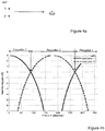
- FIG 2 shows the variations of the received power of a transmission over a pair of correlated antennas in a certain direction, over a bandwidth of 20 MHz, with a timing difference of 65 ns between the correlated antennas.
- FIG. 3a-b Another illustration can be seen in figures 3a-b , where it is shown that a UE 302 located at a fixed position may experience constructive addition of the signals (i.e. being in the main lobe) in one part of the frequency band, and experience destructive addition, e.g. a null, in another part of the frequency band.
- Two antenna pairs, such as A and B illustrated in figure 1 may in general have independent delay errors.
- absolute phase errors change the beam direction.
- An error related to the absolute phase of an antenna element is here referred to as a "absolute phase error".
- absolute phase errors may be a problem if the precoder choices are limited or if, as in figure 1 , there are two correlated pairs and the precoders are designed for specific relations between the two beams.
- the precoder choices are limited or if, as in figure 1 , there are two correlated pairs and the precoders are designed for specific relations between the two beams.
- the beam direction will be defined by the absolute phase error difference between the antennas and will not be frequency dependent (which, as previously mentioned, is the case for delay errors).
- the beams of antenna pairs A and B should preferably be aligned, i.e. have their maximum beam-forming gain in the same direction.
- P d (P 4 -P 3 ) - (P 2 -P 1 )
- P X absolute phase error on antenna element x.
- the difference in absolute phase difference between two pairs of antennas, P d is commonly referred to as a "phase error difference", and will also be referred to as such henceforth in this description.
- phase error difference (1 value) and timing errors (2 values) described above are the most important regarding system performance impact with the antenna configuration according to figure 1 .
- WO 2010/087749 A1 describes a radio base station having at least two radio chains. A relative phase error is detected between the radio chains based on compiled precoding matrix statistics. It is then possible to compensate or otherwise adjust for the detected relative phase error based on the compiled precoding matrix statistics.
- US 2010/120460 A1 describes a method and apparatus of improving the performance of a mobile radio system comprising at least one radio device having at least two transmission equipments adapted to transmit radio signals within a frequency band.
- the method comprises deriving a relative time delay of the at least two transmission equipments based on at least two sub-band transmit weight vectors, wherein a sub-band transmit weight vector comprises weight vectors applicable to the at least two transmission equipments, respectively, in a sub-band of the frequency band.
- phase affecting errors such as delay errors and phase errors, related to transmission from correlated antennas. It is an object of the invention to enable efficient determining of phase affecting errors.
- a method is provided as defined by claim 1.
- the above method and arrangement enable adjustment of transmission from the at least one pair of correlated antennas, such that said at least one phase affecting error is reduced. Further both delay errors and phase error differences could be determined in an efficient manner.
- the method and arrangement offers a solution which is direction in dependent and the determining of phase affecting errors could therefore preferably be based on reports from one single receiver, e.g. one UE. Both the magnitude and the sign of a phase error difference may be directly found by using the solution described herein.
- the accuracy and speed of the error estimation is not dependent on the error values or combination of error value.
- the most important phase and delay errors D A . D B and P d may be found from the same set of measurements. All of the above are great advantages and very useful in antenna calibration.
- the determined relation may involve one a displacement of the identified changes of selected precoder matrix over the number of controlled phase differences between frequency bands, e.g. an average of the same.
- the determined relation may be the difference in absolute phase difference, within a frequency band, between the identified changes in selected precoder matrix for two pairs of correlated antennas, for a corresponding (2-antenna) precoder matrix
- the determined phase affecting error(s) may be a delay error between transmissions from the antennas in a pair of correlated antennas, and/or a phase error difference between transmissions from two pairs of correlated antennas. Further, the transmission from the at least one pair of correlated antennas may be adjusted based on the determined phase affecting error(s).
- phase affecting errors such as, e.g., of the three phase affecting errors D A , D B and P d , e.g. for a correlated cross pole as one illustrated in figure 1 , where
- the concept described herein is based on collecting frequency selective PMI (Precoder Matrix Index) reports from a receiver while adding a phase rotation e.g. over time e.g. on a selected subset of the transmit antennas.
- the set of the PMI values available for reporting should be constructed to make the selection for each correlated pair independent of the choice for the other.
- precoder and "precoder matrix” will be used interchangeably as synonyms.
- precoder 1 For the receiving UE in figure 2 , precoder 1 will be preferred and selected, since it will produce a beam in the direction of the UE. Precoder 2, on the other hand, will make the signals from the antennas add destructively in the shown direction.
- precoder 1 for 0 ⁇ P ⁇ 90 deg.; precoder 2 for 90 ⁇ P ⁇ 270 deg., and finally precoder 1 again for 270 ⁇ P ⁇ 360 deg.
- the selection of precoder is made by the UE and signaled to the transmitting node e.g. as an indicated PMI.
- the selection of precoder is made by the UE from a set of precoders known to both the UE and the transmitting node. The selection is typically made from measurements on reference signals sent from the transmitting node without the use of any precoder from the set. That is, the reference signals are not preceded.
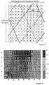
- Figure 5 shows the selected precoder as a function of the varying phase P, which is an introduced phase difference between the antennas, and also as a function of the frequency.
- a delay error is a linearly frequency dependent phase error
- the effect of the delay error may be seen in figure 5 as that the areas of selected (preferred) precoder shifts, or "moves", in relation to the controlled phase P, as the frequency changes.
- the dotted lines in figure 5 represent the borders between different selected (preferred) precoders. These borders have a slope, which, as realized by the applicant, is defined by the delay error D, which may be exploited.
- any additional non-frequency dependent phase error that is introduced between the antennas will only left- or right-shift (cyclic) the dotted lines representing the borders between different selected precoders in figure 5 , but the slope will be unaffected.
- the slope in figure 5 is therefore an estimate of the delay error D, and that estimate is independent of the direction from the transmitter to the receiving UE.
- the precoder set will handle four antennas.
- a 4-antenna precoder may be regarded as two combined 2-antenna precoders.
- the selection of a preferred (4-antenna) precoder of an entity reporting a preferred precoder to a transmitting node will then be the combination (of 2-antenna precoders) that is simultaneously preferable for both correlated pairs. This is in general not the same as the best (2-antenna) precoder for each pair.
- the properties of the used precoder set should be controlled, such that the beam forming properties of the two pairs can be separated.
- the set of available 4-antenna precoders should include all combinations of the beam-forming alternatives of the separate antenna pairs.
- the 2-antenna precoders shown above may be extended to a 4-antenna precoder set or book using all combinations of them: 1. [ 1 1 ⁇ A 1 1 ] T ⁇ B 2. [ 1 1 1 ⁇ 1 ] T 3. [ 1 1 1 ⁇ 1 ] T 4. [ 1 ⁇ 1 1 ] T where the first two positions in each precoder matrix are related to antenna pair A, and the last two positions in each precoder matrix are related to antenna pair B.
- the precoder phase difference between the antennas in each pair is either 0° or 180°. Even though this is an advantageous construction, other precoder phase differences are possible.
- the controlled phase P is now added to both antenna 2 and antenna 4, which are co-positioned but cross-polarized.
- the controlled phase P could alternatively be added to antennas 1 and 3, or divided between both antennas in each pair, such as to create the same phase difference between the two antennas.
- precoder 1 & 3 For antenna pair A, precoder 1 & 3 have the same beam forming properties ([1 1] T ) and precoder 2 & 4 together represent the other beam alternative ([1 -1] T ) for pair A.
- precoder 1 & 4 For antenna pair B, precoder 1 & 4 have the same beam forming properties ([1 1] T ) and precoder 2 & 3 together represent the other beam alternative ([1 -1] T ).
- the two leftmost dotted lines represent the same (2-antenna) precoder matrix properties, or in other words, the same (equal) precoder phase difference, e.g. 0° or 180°, between the reference signals from each correlated pair seen from the receiver.
- the introduced controlled phase difference, or phase rotation value P that results in this precoder phase difference i.e. a phase difference corresponding to the precoder matrix properties
- P d can be estimated as the difference in the compensating value P or distance between said lines, as illustrated in figure 6 .
- any lines representing the same precoder phase difference (or shift) between the reference signals from each correlated pair seen from the receiver can be used for estimating P d .
- the two leftmost dotted lines represent a precoder phase difference of 90 degrees (a selected precoder right between [1 1] T and [1 -1] T ) and the two rightmost dotted lines represent a precoder phase difference of 270 degrees (a selected precoder right between [1 -1] T and [1 1] T ).
- both the delay values D A and D B , as well as the fixed phase difference P d may be derived from a map or mapping, such as the one illustrated in figure 6 , or corresponding representation.
- precoder reports from a receiving entity are used in order to determine which precoder that is preferred or selected by the UE for each correlated antenna pair.
- the UE may be configured to send "per sub-band" precoder reports, i.e. reports in which a preferred selected precoder is indicated for each of a number of frequency sub-bands.
- the phase dependency of the precoder selection is found by introducing a controlled phase difference between the correlated antennas. This may be accomplished e.g. by a controlled phase rotation on antenna 2 and 4 over time, e.g. by adding an extra phase shift per ms.
- the controlled changes of the phase may alternatively be performed in any order, and not necessarily in a consecutively increasing order, as described here.
- a code multiplexing scheme may be used, where the phase differences or shifts are generated simultaneously, separated by a code.
- a UE may select a preferred precoder from a set of predefined precoders, which are designed for other purposes than the herein described.
- a set of precoders from which the UE can select should be restricted such that all available beam directions for antenna pair A are combined with all available beam directions of antenna pair B, in the remaining set, as previously described. This, as previously mentioned, may be referred to as that the remaining set should be "symmetric".
- precoders may have different polarization properties.
- Precoders having the same beam forming properties, although different polarization properties, may therefore be used together in groups, as will be illustrated below. Further, higher rank precoders with the same beam forming properties could also be included in the groups.
- the selected precoder group could be identified or noted, e.g. in a table/map, rather than an individual selected precoder.
- the table/map could be composed e.g. as illustrated in figure 7 , where each row represents a frequency sub-band and each column represents a step (of a number of steps between 0° and 360°) in a phase rotation.
- both one absolute phase error difference P d as well as two different delay errors D A and D B can be simultaneously extracted.
- the precoder set should be reduced to a symmetric subset of the LTE precoder book, which in fact is supported in the standard by the use of "codebook subset restriction".
- Precoders control both polarization and beam-forming properties, and therefore there are multiple precoders having identical beam forming properties that differ in polarization properties, as previously described.
- a map with the different PMI groups can be created, as the one illustrated in figure 7 .
- the rows represent frequency sub-bands
- the columns represent different phase rotations.
- the timing errors D A and D B can be calculated.
- the borders, or lines fitted to the borders, are also related in absolute terms, which make it possible to also find the differences of the phase (shift) differences P d between the correlated pairs.
- t x and d xn represent delay and phase error on antenna x on sub-band n:
- P A and P B represent the estimated values per sub-band, of the phase rotation value P where the phase difference between the reference signals in each correlated pair, A and B have 0 degrees phase difference.
- the sample with max absolute value from the DFT in step 15 and 16 is an estimation of how much the phase rotation value P, resulting in a phase difference of 0 degrees explained above, is changed per sub-band. That is, an estimation of the slope of the lines in e.g. figure 7 .
- Step 17 and 18 converts the result to the corresponding delay error.
- precoder groups 1 and 2 illustrated by different patterns in figure 8 , hold the same beam forming properties represented by a 0 degree phase difference between the two antenna elements.
- precoder group 3 or 4 On the other positions, where precoder group 3 or 4 is chosen, add complex values with magnitude 1 and phase 180 deg. (i.e. the real number -1) corresponding to the phase difference between the antennas in pair A for groups 3 and 4.
- the new map will then hold one of two values (1 or -1) in each of its elements.
- the pattern of "1" and “-1” will be cyclic and the values will represent a phase rotation going from left to right. In this exemplifying case the phase is quantized in two values, 0 and 180 degrees.
- the task is to estimate the position with 0 degrees phase difference, i.e. the "middle" of the field with ones, which is representing a 0 degree phase difference (shift) between the received reference signals.
- One way to do this is to take the sum of each row weighted with a fixed phase rotation.
- a slope should be estimated in order to get an indication of the delay error.
- the value that we are looking for is in fact the average phase shift (of the value change pattern) per sub-band of P and that is precisely what the Fourier transform, or DFT, of P gives us.
- the phase shift represented by the DFT output domain sample with the largest absolute value is an estimate of the delay error, steps 15-18, where e.g. Rind A is the index to the DFT output sample with the largest absolute value, S BW is the sub-band bandwidth and S is the number of sub-bands which in this case is the same as the DFT size.
- the DFT size can be larger than the number of values in P (which is the number of sub-bands) by padding P with zeros before the DFT to increase granularity.
- phase difference P d For the estimation of the phase difference P d , also the phase of the frequency domain sample Rind A is used. Comparing these phase values for the two antenna pairs will hold as an estimate of the absolute phase difference, step 19.
- P An and P Bn is the phases of DFT sample number Rind A and Rind B of antenna pair A and B, respectively, and n is the sub-band number starting with 0 for the sub-band with lowest frequency.
- Figure 9a and figure 9b show simulation results of the calibration accuracy after 72 received PMI reports per sub-band.
- the required accuracy is around 20 ns for D A and D B and around 45 degrees for P d .
- the diagram in figure 9a could be read as that 98% of the randomly chosen UEs, that were used for the calibration procedure, were able to correct the delay error of the base station antennas to a value below 20 ns after 72 PMI reports.
- the diagram in figure 9b could be read as that 96% of the randomly chosen UEs, that were used for the calibration procedure, were able to correct the difference of the phase difference P d at the base station antennas to a value below 45°.
- the results appear to be relatively insensitive to the initial error combinations or absolute values.
- the procedure(s) could be performed in a network node which is associated with or directly controls the correlated antennas, i.e. a node that uses the correlated antennas for transmission, such as e.g. an RBS, such as an eNB, or similar.
- the procedure could be performed in a network node which is not associated with or directly controls the correlated antennas, i.e. a node which does not itself use the correlated antennas for transmission, such as e.g. an OAM (Operations, Administration & Maintenance) node.
- OAM Order, Administration & Maintenance
- Reference signals are transmitted from the correlated first and second antennas in the at least one pair, in one or more actions 1002.
- the reference signals are transmitted in a set of frequency bands and a number of controlled phase differences are introduced between the antennas of a pair. That is, a number of controlled phase differences, e.g. between 0° and 360° are introduced between reference signals transmitted from the first antenna in relation to reference signals transmitted from the second antenna.
- one or more indications of a selected precoder matrix are received, in one or more actions 1004, from another entity, such as a mobile terminal, in a direction from the antennas.
- the one or more indications are received in response to the transmitted reference signals, and relate to a number of the controlled phase differences. For example, one indication per controlled phase difference and frequency band could be received (cf. e.g. one indication per row for each column in figures 7 and 8 ).
- changes of selected precoder matrix are identified in one or more actions 1006, based on the one or more received indications. Changes between different controlled phase differences and over the set of frequency bands are identified. At least one relation between the identified changes is determined in an action 1008.
- At least one phase affecting error associated with the transmission from the at least one pair of correlated antennas is determined in one or more actions 1010, based on the at least one determined relation.
- the at least one phase affecting error could be a delay error between transmissions from the antennas in a pair, and/or a phase error difference between two pairs of correlated antennas. This enables adjustment of the transmission from the correlated antennas, such that the determined error or errors may be reduced, which may result in a number of advantages.
- transmitting may refer e.g. to inducing or triggering transmission from the antennas, etc.
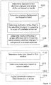
- the displacement, between frequency bands, of the identified changes may be determined e.g. in an action 1102 (c.f. how the border between selected precoder shifts between rows in figures 7 and 8 .)
- the average displacement in phase difference (phase shift) per frequency band of the changes of selected precoder matrix may be determined e.g. in an action 1104.
- the term "displacement" refers to what in a graphical representation, e.g. figure 6 or 7 , may be seen as a displacement or movement along the x-axis.
- the average displacement in phase difference per frequency band refers to what in a graphical representation, e.g. figure 6 or 7 , may be seen as the slope of a line fitted to a border between different selected precoders.
- a relation may be determined, e.g. in an action 1106, as the inclination of a line fitted to the identified changes of selected precoder matrix in a map, such as a controlled phase difference vs. frequency band mapping, for a pair of correlated antennas.
- the difference in absolute phase difference, within a frequency band, between the identified changes in selected precoder matrix for two pairs of correlated antennas may be determined e.g. in an action 1108.
- This relation may be determined e.g. as the distance, in phase difference, between lines fitted to the identified changes of selected precoder for two pairs of correlated antennas in a map as the ones illustrated in figures 7 and 8 .
- the lines should be fitted to equal precoder properties for both antenna pairs, e.g. changes to or from a corresponding precoder matrix for both antenna pairs, i.e. a (2-antenna) precoder matrix having the same beam forming properties (phase shift), e.g. [1 1] T .
- one or more phase affecting errors may be determined. For example, a delay error between transmissions from the antennas in a pair of correlated antennas may be determined in an action 1110, based on a relation determined in one of actions 1102-1106. Further, a phase error may be determined in an action 1112, based on a relation determined in action 1108.
- a phase error may be determined from a relation determined for only one frequency band. However, for determining a delay error, information related to at least two frequency bands is required.
- a set of precoder matrices, from which the precoder matrix is selected, is preferably configured such that precoder matrix selections for different antenna pairs are made independent of each other.
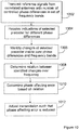
- Figure 12 illustrates a procedure according to an exemplifying embodiment, wherein a relation associated with delay error is determined in an action 1202. When said relation is determined, a delay error is determined in an action 1204. If the procedure is performed for more than one pair of correlated antennas, a relation associated with phase error may be determined in an action 1208. A phase error between pairs of antennas may be determined in an action 1210, and the transmission may then be adjusted in an action 1212, based on the estimated delay error and/or phase error.
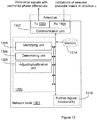
- the arrangement is suitable for use in a network node and is illustrated as being located in a network node 1301 in figure 13 .
- the network node could be e.g. an eNB or similar, a mobile terminal, or an OAM node in a communication system.
- the arrangement 1300 is further illustrated as to communicate with other entities via a communication unit 1302 which may be regarded as part of the arrangement 1300.
- the arrangement or network node may further comprise other functional units 1316, such as e.g. functional units providing regular eNB or mobile terminal functions, and may further comprise one or more storage units 1314.
- the arrangement is adapted for use in a transmitting network node, which directly controls the correlated antennas in question.
- the arrangement could alternatively be adapted for use in another node, which does not directly control the correlated antennas in question, as previously described.
- the actions of transmitting etc. from the antennas would then be performed by inducing or triggering a node controlling the antennas to perform said actions in an explicit or implicit manner.
- the arrangement 1300 could be implemented e.g. by one or more of: a processor or a micro processor and adequate software and memory for storing thereof, a Programmable Logic Device (PLD) or other electronic component(s) or processing circuitry configured to perform the actions described above.
- PLD Programmable Logic Device
- the arrangement comprises a transmitter 1303, adapted to transmit reference signals from the correlated first and second antennas in the at least one pair, in a set of frequency bands, wherein a number of controlled phase differences are introduced between reference signals transmitted from the first antenna in relation to reference signals transmitted from the second antenna.
- the arrangement further comprises a receiver 1304, adapted to receive, from another entity, such as a mobile terminal in response to the transmitted reference signals, for a number of the controlled phase differences, one or more indications of a selected precoder matrix.
- the arrangement further comprises an identifying unit 1305, adapted to identify changes of selected precoder matrix over the controlled number of phase differences, over the set of frequency bands, wherein the identifying is based on the received one or more indications.
- the arrangement further comprises a determining unit 1306, adapted to determine at least one relation between the identified changes of selected precoder matrix over the number of controlled phase differences and set of frequency bands; and further adapted to determine at least one phase affecting error associated with the transmission from the at least one pair of correlated antennas based on said at least one relation.
- the arrangement may further comprise an adjusting or calibrating unit 1308, adapted to adjust the transmission from the at least one pair of correlated antennas, such that said at least one phase affecting error is reduced.
- FIG 14 schematically shows a possible embodiment of an arrangement 1400, which also can be an alternative way of disclosing an embodiment of the arrangement illustrated in figure 13 .
- a processing unit 1406 e.g. with a DSP (Digital Signal Processor).
- the processing unit 1406 may be a single unit or a plurality of units to perform different actions of procedures described herein.
- the arrangement 1400 may also comprise an input unit 1402 for receiving signals from other entities, and an output unit 1404 for providing signal(s) to other entities.
- the input unit 1402 and the output unit 1404 may be arranged as an integrated entity.
- the arrangement 1400 comprises at least one computer program product 1408 in the form of a non-volatile memory, e.g. an EEPROM (Electrically Erasable Programmable Read-Only Memory), a flash memory and a hard derive.
- the computer program product 1408 comprises a computer program 1410, which comprises code means, which when executed in the processing unit 1406 in the arrangement 1400 causes the arrangement and/or a node in which the arrangement is comprised to perform the actions e.g. of the procedure described earlier in conjunction with figures 10-12 .
- the computer program 1410 may be configured as a computer program code structured in computer program modules.
- the code means in the computer program 1410 of the arrangement 1400 may comprise a control module 1410a for arranging transmission of reference signals from the correlated first and second antennas in the at least one pair, in a set of frequency bands, wherein a number of controlled phase differences are introduced between reference signals transmitted from the first antenna in relation to reference signals transmitted from the second antenna.
- the arrangement 1400 may further comprise a receiving module 1410b for receiving, in response to the transmitted reference signals one or more indications of a selected precoder matrix;
- the computer program may further comprise an identifying module 1410c for identifying changes of selected precoder matrix over the controlled number of phase differences, over the set of frequency bands.
- the computer program 1410 may further comprise a determining module 1410d for determining at least one relation between the ideritified changes of selected precoder matrix over the number of controlled phase differences and set of frequency bands; and further adapted to determine at least one phase affecting error associated with the transmission from the at least one pair of correlated antennas based on said at least one relation.
- the modules 1410a-d could essentially perform the actions of the flows illustrated in figures 10-12 , to emulate the arrangement illustrated in figure 13 .
- code means in the embodiment disclosed above in conjunction with figure 14 are implemented as computer program modules which when executed in the processing unit causes the decoder to perform the actions described above in the conjunction with figures mentioned above, at least one of the code means may in alternative embodiments be implemented at least partly as hardware circuits.
- the processor may be a shingle CPU (Central processing unit), but could also comprise two or more processing units.
- the processor may include general purpose microprocessors; instruction set processors and/or related chips sets and/or special purpose microprocessors such as ASPICs (Application Specific Integrated Circuit).
- the processor may also comprise board memory for caching purposes.
- the computer program may be carried by a computer program product connected to the processor.
- the computer program product may comprise a computer readable medium on which the computer program is stored.
- the computer program product may be a flash memory, a RAM (Random-access memory) ROM (Read-Only Memory) or an EEPROM, and the computer program modules described above could in alternative embodiments be distributed on different computer program products in the form of memories within the network node.
Landscapes
- Engineering & Computer Science (AREA)
- Computer Networks & Wireless Communication (AREA)
- Signal Processing (AREA)
- Physics & Mathematics (AREA)
- Mathematical Physics (AREA)
- Power Engineering (AREA)
- Electromagnetism (AREA)
- Radio Transmission System (AREA)
- Variable-Direction Aerials And Aerial Arrays (AREA)
Claims (15)
- Procédé dans un noeud d'émission dans un système de communication sans fil pour déterminer au moins une erreur affectant une phase associée à une émission à partir d'au moins une paire d'antennes corrélées comprenant des première et deuxième antennes, le procédé comprenant :- l'émission (1002) de signaux de référence à partir des première et deuxième antennes corrélées de ladite au moins une paire, dans un ensemble de bandes de fréquence, dans lequel un certain nombre de différences de phase commandées sont introduites entre les signaux de référence émis à partir de la première antenne par rapport aux signaux de référence émis à partir la deuxième antenne ;- la réception (1004), à partir d'une autre entité, en réponse aux signaux de référence émis, pour un certain nombre des différences de phase commandées, d'une indication ou plus d'une matrice de précodeur sélectionnée ;- l'identification (1006) des changements de la matrice de précodeur sélectionnée sur le nombre de différences de phase commandées, sur l'ensemble de bandes de fréquence, dans lequel l'identification est basée sur lesdites une ou plusieurs indications reçues ;- la détermination (1008) d'au moins une relation entre les changements identifiés de la matrice de précodeur sélectionnée sur le nombre de différences de phase commandées et sur l'ensemble de bandes de fréquence ; et- la détermination (1010) d'au moins une erreur affectant une phase associée à l'émission à partir de ladite au moins une paire d'antennes corrélées sur la base de ladite au moins une relation, dans lequel l'une de ladite au moins une relation déterminée est l'inclinaison d'une droite ajustée aux changements identifiés de la matrice de précodeur sélectionnée dans un mappage de la différence de phase commandée vers la bande de fréquence pour une paire d'antennes corrélées,permettant ainsi l'ajustement de l'émission à partir de ladite au moins une paire d'antennes corrélées, de sorte que ladite au moins une erreur affectant une phase soit réduite.
- Procédé selon la revendication 1, dans lequel l'une de ladite au moins une relation déterminée implique le déplacement des changements identifiés de la matrice de précodeur sélectionnée sur le nombre de différences de phase commandées entre les bandes de fréquence.
- Procédé selon la revendication 1 ou 2, dans lequel l'une de ladite au moins une relation déterminée est le déplacement moyen de la différence de phase par bande de fréquence, des changements de la matrice de précodeur sélectionnée.
- Procédé selon l'une quelconque des revendications précédentes, dans lequel l'au moins une des erreurs affectant une phase est une erreur de retard entre les émissions à partir des antennes dans ladite au moins une paire d'antennes corrélées.
- Procédé selon l'une quelconque des revendications précédentes, dans lequel une relation déterminée est la différence de la différence de phase absolue, dans une bande de fréquence, entre les changements identifiés de la matrice de précodeur sélectionnée pour deux paires d'antennes corrélées.
- Procédé selon l'une quelconque des revendications précédentes, dans lequel l'au moins une des erreurs affectant une phase est une différence d'erreur de phase entre les émissions à partir de deux paires d'antennes corrélées.
- Procédé selon l'une quelconque des revendications précédentes, dans lequel un ensemble de matrices de précodeur, dans lequel la matrice de précodeur est sélectionnée, est configuré de sorte que les sélections de matrice de précodeur pour différentes paires d'antennes soient effectuées de manière indépendantes les unes des autres.
- Procédé selon l'une quelconque des revendications précédentes, comprenant en outre :- l'ajustement (1012) de l'émission à partir de ladite au moins une paire d'antennes corrélées sur la base de l'erreur affectant une phase déterminée.
- Agencement (1300) pour un noeud d'émission (1301) dans un système de communication sans fil pour déterminer au moins une erreur affectant une phase concernant une émission à partir d'au moins une paire d'antennes corrélées comprenant des première et deuxième antennes, ledit agencement comprenant :- un émetteur (1303), conçu pour émettre des signaux de référence à partir des première et deuxième antennes corrélées de ladite au moins une paire, dans un ensemble de bandes de fréquence, dans lequel un certain nombre de différences de phase commandées sont introduites entre les signaux de référence émis à partir de la première antenne par rapport aux signaux de référence émis à partir de la deuxième antenne ;- un récepteur (1304), conçu pour recevoir, d'une autre entité, en réponse aux signaux de référence émis, pour un certain nombre des différences de phase commandées, une ou plusieurs indications d'une matrice de précodeur sélectionnée ;- une unité d'identification (1305), conçue pour identifier les changements de la matrice de précodeur sélectionnée sur le nombre de différences de phase commandées, sur l'ensemble des bandes de fréquence, dans lequel l'identification est basée sur lesdites une ou plusieurs indications reçues ;- une unité de détermination (1306), conçue pour déterminer au moins une relation entre les changements identifiés de la matrice de précodeur sélectionnée sur le nombre de différences de phase commandées et sur l'ensemble de bandes de fréquence ; et en outre conçue pour déterminer au moins une erreur affectant une phase associée à l'émission à partir de ladite au moins une paire d'antennes corrélées sur la base de ladite au moins une relation, dans lequel l'unité de détermination est en outre conçue pour déterminer une relation sous la forme de l'inclinaison d'une droite ajustée aux changements identifiés de la matrice de précodeur sélectionnée dans un mappage de la différence de phase commandée vers la bande de fréquence pour une paire d'antennes corrélées,permettant ainsi l'ajustement de l'émission à partir de ladite au moins une paire d'antennes corrélées, de sorte que ladite au moins une erreur affectant une phase soit réduite.
- Agencement selon la revendication 9, dans lequel l'unité de détermination est conçue pour déterminer une relation sous la forme du déplacement des changements identifiés de la matrice de précodeur sélectionnée sur le nombre de différences de phase commandées entre les bandes de fréquence.
- Agencement selon la revendication 9 ou 10, dans lequel l'unité de détermination est conçue pour déterminer une relation sous la forme du déplacement moyen de la différence de phase par bande de fréquence, des changements de la matrice de précodeur sélectionnée.
- Agencement selon l'une quelconque des revendications 9 à 11, dans lequel l'unité de détermination est conçue pour déterminer une erreur affectant une phase sous la forme d'une erreur de retard entre les émissions à partir des antennes dans une paire d'antennes corrélées sur la base d'une relation déterminée pour ladite paire d'antennes corrélées.
- Agencement selon l'une quelconque des revendications 9 à 12, dans lequel l'unité de détermination est conçue pour déterminer une différence de la différence de phase absolue, dans une bande de fréquence, entre les changements identifiés de la matrice de précodeur sélectionnée pour deux paires d'antennes corrélées.
- Agencement selon l'une quelconque des revendications 9 à 13, dans lequel l'unité de détermination est conçue pour déterminer une erreur affectant une phase sous la forme d'une différence d'erreur de phase entre les émissions à partir de deux paires d'antennes corrélées sur la base de ladite au moins une relation déterminée.
- Agencement selon l'une quelconque des revendications 9 à 14, comprenant en outre une unité d'ajustement (1308), conçue pour ajuster l'émission à partir de ladite au moins une paire d'antennes corrélées sur la base de l'erreur affectant une phase déterminée.
Applications Claiming Priority (1)
| Application Number | Priority Date | Filing Date | Title |
|---|---|---|---|
| PCT/SE2012/050120 WO2013119152A1 (fr) | 2012-02-08 | 2012-02-08 | Procédé et agencement destinés à permettre le réglage d'une émission à partir d'antennes corrélées |
Publications (2)
| Publication Number | Publication Date |
|---|---|
| EP2817892A1 EP2817892A1 (fr) | 2014-12-31 |
| EP2817892B1 true EP2817892B1 (fr) | 2017-07-19 |
Family
ID=45757762
Family Applications (1)
| Application Number | Title | Priority Date | Filing Date |
|---|---|---|---|
| EP12705921.0A Not-in-force EP2817892B1 (fr) | 2012-02-08 | 2012-02-08 | Procédé et agencement destinés à permettre le réglage d'une émission à partir d'antennes corrélées |
Country Status (3)
| Country | Link |
|---|---|
| US (1) | US9143217B2 (fr) |
| EP (1) | EP2817892B1 (fr) |
| WO (1) | WO2013119152A1 (fr) |
Cited By (1)
| Publication number | Priority date | Publication date | Assignee | Title |
|---|---|---|---|---|
| WO2024164102A1 (fr) * | 2023-02-06 | 2024-08-15 | Telefonaktiebolaget Lm Ericsson (Publ) | Procédés, appareil et supports lisibles par ordinateur associés à l'estimation d'erreur de phase |
Families Citing this family (14)
| Publication number | Priority date | Publication date | Assignee | Title |
|---|---|---|---|---|
| JP5908307B2 (ja) * | 2012-03-06 | 2016-04-26 | シャープ株式会社 | プリコーディング装置、無線送信装置、無線受信装置、無線通信システムおよび集積回路 |
| KR20150035705A (ko) * | 2012-07-03 | 2015-04-07 | 엘지전자 주식회사 | 무선 통신 시스템에서 3차원 빔포밍을 위한 채널 상태 정보를 보고하는 방법 및 이를 위한 장치 |
| CN103944621B (zh) * | 2013-01-18 | 2017-12-05 | 上海贝尔股份有限公司 | 确定适用于4Tx交叉极化天线配置的两级码本集合的方法 |
| CN105765931B (zh) * | 2013-08-16 | 2019-02-15 | 瑞典爱立信有限公司 | 保持相位相干性以用于频率偏移估算 |
| US9848428B2 (en) | 2013-08-27 | 2017-12-19 | Telefonaktiebolaget Lm Ericsson (Publ) | Positioning of wireless devices |
| US10123362B2 (en) | 2013-12-18 | 2018-11-06 | Telefonaktiebolaget Lm Ericsson (Publ) | Operation of a multi-standard base station site supporting at least two different radio access technologies |
| WO2015126289A1 (fr) | 2014-02-19 | 2015-08-27 | Telefonaktiebolaget L M Ericsson (Publ) | Transmission de données sur un nombre réduit d'antennes physiques |
| CN110463069A (zh) * | 2017-04-07 | 2019-11-15 | 瑞典爱立信有限公司 | 用于无线通信网络中的预编码控制的方法和装置 |
| CN110521129B (zh) | 2017-04-07 | 2022-05-17 | 瑞典爱立信有限公司 | 用于无线通信网络中的预编码控制的方法和装置 |
| CN110365380B (zh) * | 2018-04-10 | 2021-12-14 | 成都华为技术有限公司 | 数据传输的方法、通信装置及系统 |
| US11095348B2 (en) | 2019-08-16 | 2021-08-17 | Lg Electronics Inc. | Method and apparatus for uplink signal transmission based on codebook in a wireless communication system |
| US11101856B2 (en) * | 2019-08-16 | 2021-08-24 | Lg Electronics Inc. | Method and apparatus for uplink signal transmission based on codebook in a wireless communication system |
| WO2021079173A1 (fr) * | 2019-10-23 | 2021-04-29 | Telefonaktiebolaget Lm Ericsson (Publ) | Compensation d'erreur de phase destinée à des systèmes de liaison descendante avec quatre antennes corrélées et non étalonnées |
| WO2021171167A1 (fr) | 2020-02-26 | 2021-09-02 | Telefonaktiebolaget Lm Ericsson (Publ) | Estimation/compensation d'erreur de synchronisation pour systèmes de liaison descendante 5g nr avec des antennes non étalonnées |
Family Cites Families (5)
| Publication number | Priority date | Publication date | Assignee | Title |
|---|---|---|---|---|
| JP4845640B2 (ja) | 2006-08-23 | 2011-12-28 | 富士通株式会社 | 無線通信システムおよび無線通信方法 |
| WO2008082344A1 (fr) | 2007-01-04 | 2008-07-10 | Telefonaktiebolaget L M Ericsson (Publ) | Procédé et appareil d'amélioration du rendement de transmission dans un système de radiocommunication mobile |
| WO2010087749A1 (fr) * | 2009-01-30 | 2010-08-05 | Telefonaktiebolaget Lm Ericsson (Publ) | Étalonnage de phase et détection de câblage erroné pour station de base radio à antennes multiples |
| US8687555B2 (en) * | 2010-09-29 | 2014-04-01 | Lg Electronics Inc. | Method and apparatus for performing effective feedback in wireless communication system supporting multiple antennas |
| US9380466B2 (en) * | 2013-02-07 | 2016-06-28 | Commscope Technologies Llc | Radio access networks |
-
2012
- 2012-02-08 WO PCT/SE2012/050120 patent/WO2013119152A1/fr not_active Ceased
- 2012-02-08 EP EP12705921.0A patent/EP2817892B1/fr not_active Not-in-force
- 2012-02-08 US US14/376,064 patent/US9143217B2/en active Active
Non-Patent Citations (1)
| Title |
|---|
| None * |
Cited By (1)
| Publication number | Priority date | Publication date | Assignee | Title |
|---|---|---|---|---|
| WO2024164102A1 (fr) * | 2023-02-06 | 2024-08-15 | Telefonaktiebolaget Lm Ericsson (Publ) | Procédés, appareil et supports lisibles par ordinateur associés à l'estimation d'erreur de phase |
Also Published As
| Publication number | Publication date |
|---|---|
| EP2817892A1 (fr) | 2014-12-31 |
| US20150215023A1 (en) | 2015-07-30 |
| US9143217B2 (en) | 2015-09-22 |
| WO2013119152A1 (fr) | 2013-08-15 |
Similar Documents
| Publication | Publication Date | Title |
|---|---|---|
| EP2817892B1 (fr) | Procédé et agencement destinés à permettre le réglage d'une émission à partir d'antennes corrélées | |
| CN114128161B (zh) | 在无线通信系统中用于csi报告的方法和设备 | |
| US11652515B2 (en) | Method and device for feeding back channel state information, and method and device for determining channel state information | |
| CN107196749B (zh) | 一种信道状态信息测量、参考信号的发送方法和装置 | |
| CN107836089B (zh) | 混合波束成形多天线无线系统 | |
| EP2553823B1 (fr) | Livres de codage de précodeur pour des canaux efficaces ayant une sélectivité de fréquence structurée | |
| EP2950458A1 (fr) | Procédé de renvoi d'informations d'état de canal, procédé d'émission d'un signal de référence d'informations d'état de canal, équipement d'utilisateur et station de base | |
| US8861639B2 (en) | Method for determining precoding matrix and corresponding communication methods and devices | |
| WO2016051792A1 (fr) | Procédé et système de communication mimo | |
| EP3537620B1 (fr) | Procédé et appareil de rétroaction de quantification d'informations de canal, dispositif électronique et support d'informations | |
| US20250226865A1 (en) | Port-group specific precoding parameter sets for cjt with m-trp | |
| US20130114654A1 (en) | Precoding feedback for cross-polarized antennas with magnitude information | |
| US20200274597A1 (en) | Feedback method and device for channel information | |
| EP3343791B1 (fr) | Procédés et appareils pour transmettre des informations d'indication de codage et déterminer une matrice de précodage | |
| CN105245310A (zh) | 一种下行导频信号的处理方法及系统 | |
| CN110149129B (zh) | 确定波束赋型权值的方法、装置及设备 | |
| CN109075904A (zh) | 一种预编码矩阵指示的反馈方法及装置 | |
| US10020857B2 (en) | Precoding a transmission from an antenna array that includes co-polarized antenna elements aligned in a given spatial dimension | |
| US9484997B2 (en) | Determining a precoder of a codebook | |
| CN108270473B (zh) | 一种数据处理方法、用户设备和无线接入设备 | |
| EP2731277B1 (fr) | Procédé, dispositif et système d'émission multi-antenne | |
| US20140376600A1 (en) | Low Complexity and Accurate Cluster of Beams Selection | |
| EP3383089A1 (fr) | Procédé et dispositif d'acquisition d'informations de canal | |
| EP2775563A1 (fr) | N'ud de réseau et procédé | |
| US9780849B2 (en) | Method and system for performance testing |
Legal Events
| Date | Code | Title | Description |
|---|---|---|---|
| PUAI | Public reference made under article 153(3) epc to a published international application that has entered the european phase |
Free format text: ORIGINAL CODE: 0009012 |
|
| 17P | Request for examination filed |
Effective date: 20140812 |
|
| AK | Designated contracting states |
Kind code of ref document: A1 Designated state(s): AL AT BE BG CH CY CZ DE DK EE ES FI FR GB GR HR HU IE IS IT LI LT LU LV MC MK MT NL NO PL PT RO RS SE SI SK SM TR |
|
| AX | Request for extension of the european patent |
Extension state: BA ME |
|
| DAX | Request for extension of the european patent (deleted) | ||
| GRAP | Despatch of communication of intention to grant a patent |
Free format text: ORIGINAL CODE: EPIDOSNIGR1 |
|
| STAA | Information on the status of an ep patent application or granted ep patent |
Free format text: STATUS: GRANT OF PATENT IS INTENDED |
|
| RIC1 | Information provided on ipc code assigned before grant |
Ipc: H04B 7/06 20060101ALI20170130BHEP Ipc: H04L 25/03 20060101ALI20170130BHEP Ipc: H04B 7/04 20170101AFI20170130BHEP Ipc: H04B 17/00 20150101ALI20170130BHEP Ipc: H04B 17/11 20150101ALI20170130BHEP |
|
| INTG | Intention to grant announced |
Effective date: 20170214 |
|
| GRAS | Grant fee paid |
Free format text: ORIGINAL CODE: EPIDOSNIGR3 |
|
| GRAA | (expected) grant |
Free format text: ORIGINAL CODE: 0009210 |
|
| STAA | Information on the status of an ep patent application or granted ep patent |
Free format text: STATUS: THE PATENT HAS BEEN GRANTED |
|
| AK | Designated contracting states |
Kind code of ref document: B1 Designated state(s): AL AT BE BG CH CY CZ DE DK EE ES FI FR GB GR HR HU IE IS IT LI LT LU LV MC MK MT NL NO PL PT RO RS SE SI SK SM TR |
|
| REG | Reference to a national code |
Ref country code: GB Ref legal event code: FG4D |
|
| REG | Reference to a national code |
Ref country code: CH Ref legal event code: EP |
|
| REG | Reference to a national code |
Ref country code: IE Ref legal event code: FG4D |
|
| REG | Reference to a national code |
Ref country code: AT Ref legal event code: REF Ref document number: 911326 Country of ref document: AT Kind code of ref document: T Effective date: 20170815 |
|
| REG | Reference to a national code |
Ref country code: DE Ref legal event code: R096 Ref document number: 602012034675 Country of ref document: DE |
|
| REG | Reference to a national code |
Ref country code: NL Ref legal event code: MP Effective date: 20170719 |
|
| REG | Reference to a national code |
Ref country code: LT Ref legal event code: MG4D |
|
| REG | Reference to a national code |
Ref country code: AT Ref legal event code: MK05 Ref document number: 911326 Country of ref document: AT Kind code of ref document: T Effective date: 20170719 |
|
| PG25 | Lapsed in a contracting state [announced via postgrant information from national office to epo] |
Ref country code: NL Free format text: LAPSE BECAUSE OF FAILURE TO SUBMIT A TRANSLATION OF THE DESCRIPTION OR TO PAY THE FEE WITHIN THE PRESCRIBED TIME-LIMIT Effective date: 20170719 Ref country code: LT Free format text: LAPSE BECAUSE OF FAILURE TO SUBMIT A TRANSLATION OF THE DESCRIPTION OR TO PAY THE FEE WITHIN THE PRESCRIBED TIME-LIMIT Effective date: 20170719 Ref country code: SE Free format text: LAPSE BECAUSE OF FAILURE TO SUBMIT A TRANSLATION OF THE DESCRIPTION OR TO PAY THE FEE WITHIN THE PRESCRIBED TIME-LIMIT Effective date: 20170719 Ref country code: FI Free format text: LAPSE BECAUSE OF FAILURE TO SUBMIT A TRANSLATION OF THE DESCRIPTION OR TO PAY THE FEE WITHIN THE PRESCRIBED TIME-LIMIT Effective date: 20170719 Ref country code: AT Free format text: LAPSE BECAUSE OF FAILURE TO SUBMIT A TRANSLATION OF THE DESCRIPTION OR TO PAY THE FEE WITHIN THE PRESCRIBED TIME-LIMIT Effective date: 20170719 Ref country code: HR Free format text: LAPSE BECAUSE OF FAILURE TO SUBMIT A TRANSLATION OF THE DESCRIPTION OR TO PAY THE FEE WITHIN THE PRESCRIBED TIME-LIMIT Effective date: 20170719 Ref country code: NO Free format text: LAPSE BECAUSE OF FAILURE TO SUBMIT A TRANSLATION OF THE DESCRIPTION OR TO PAY THE FEE WITHIN THE PRESCRIBED TIME-LIMIT Effective date: 20171019 |
|
| PG25 | Lapsed in a contracting state [announced via postgrant information from national office to epo] |
Ref country code: BG Free format text: LAPSE BECAUSE OF FAILURE TO SUBMIT A TRANSLATION OF THE DESCRIPTION OR TO PAY THE FEE WITHIN THE PRESCRIBED TIME-LIMIT Effective date: 20171019 Ref country code: ES Free format text: LAPSE BECAUSE OF FAILURE TO SUBMIT A TRANSLATION OF THE DESCRIPTION OR TO PAY THE FEE WITHIN THE PRESCRIBED TIME-LIMIT Effective date: 20170719 Ref country code: RS Free format text: LAPSE BECAUSE OF FAILURE TO SUBMIT A TRANSLATION OF THE DESCRIPTION OR TO PAY THE FEE WITHIN THE PRESCRIBED TIME-LIMIT Effective date: 20170719 Ref country code: LV Free format text: LAPSE BECAUSE OF FAILURE TO SUBMIT A TRANSLATION OF THE DESCRIPTION OR TO PAY THE FEE WITHIN THE PRESCRIBED TIME-LIMIT Effective date: 20170719 Ref country code: PL Free format text: LAPSE BECAUSE OF FAILURE TO SUBMIT A TRANSLATION OF THE DESCRIPTION OR TO PAY THE FEE WITHIN THE PRESCRIBED TIME-LIMIT Effective date: 20170719 Ref country code: IS Free format text: LAPSE BECAUSE OF FAILURE TO SUBMIT A TRANSLATION OF THE DESCRIPTION OR TO PAY THE FEE WITHIN THE PRESCRIBED TIME-LIMIT Effective date: 20171119 Ref country code: GR Free format text: LAPSE BECAUSE OF FAILURE TO SUBMIT A TRANSLATION OF THE DESCRIPTION OR TO PAY THE FEE WITHIN THE PRESCRIBED TIME-LIMIT Effective date: 20171020 |
|
| REG | Reference to a national code |
Ref country code: DE Ref legal event code: R097 Ref document number: 602012034675 Country of ref document: DE |
|
| PG25 | Lapsed in a contracting state [announced via postgrant information from national office to epo] |
Ref country code: CZ Free format text: LAPSE BECAUSE OF FAILURE TO SUBMIT A TRANSLATION OF THE DESCRIPTION OR TO PAY THE FEE WITHIN THE PRESCRIBED TIME-LIMIT Effective date: 20170719 Ref country code: RO Free format text: LAPSE BECAUSE OF FAILURE TO SUBMIT A TRANSLATION OF THE DESCRIPTION OR TO PAY THE FEE WITHIN THE PRESCRIBED TIME-LIMIT Effective date: 20170719 Ref country code: DK Free format text: LAPSE BECAUSE OF FAILURE TO SUBMIT A TRANSLATION OF THE DESCRIPTION OR TO PAY THE FEE WITHIN THE PRESCRIBED TIME-LIMIT Effective date: 20170719 |
|
| PLBE | No opposition filed within time limit |
Free format text: ORIGINAL CODE: 0009261 |
|
| STAA | Information on the status of an ep patent application or granted ep patent |
Free format text: STATUS: NO OPPOSITION FILED WITHIN TIME LIMIT |
|
| PG25 | Lapsed in a contracting state [announced via postgrant information from national office to epo] |
Ref country code: SM Free format text: LAPSE BECAUSE OF FAILURE TO SUBMIT A TRANSLATION OF THE DESCRIPTION OR TO PAY THE FEE WITHIN THE PRESCRIBED TIME-LIMIT Effective date: 20170719 Ref country code: EE Free format text: LAPSE BECAUSE OF FAILURE TO SUBMIT A TRANSLATION OF THE DESCRIPTION OR TO PAY THE FEE WITHIN THE PRESCRIBED TIME-LIMIT Effective date: 20170719 Ref country code: SK Free format text: LAPSE BECAUSE OF FAILURE TO SUBMIT A TRANSLATION OF THE DESCRIPTION OR TO PAY THE FEE WITHIN THE PRESCRIBED TIME-LIMIT Effective date: 20170719 Ref country code: IT Free format text: LAPSE BECAUSE OF FAILURE TO SUBMIT A TRANSLATION OF THE DESCRIPTION OR TO PAY THE FEE WITHIN THE PRESCRIBED TIME-LIMIT Effective date: 20170719 |
|
| 26N | No opposition filed |
Effective date: 20180420 |
|
| PG25 | Lapsed in a contracting state [announced via postgrant information from national office to epo] |
Ref country code: SI Free format text: LAPSE BECAUSE OF FAILURE TO SUBMIT A TRANSLATION OF THE DESCRIPTION OR TO PAY THE FEE WITHIN THE PRESCRIBED TIME-LIMIT Effective date: 20170719 |
|
| REG | Reference to a national code |
Ref country code: CH Ref legal event code: PL |
|
| PG25 | Lapsed in a contracting state [announced via postgrant information from national office to epo] |
Ref country code: MC Free format text: LAPSE BECAUSE OF FAILURE TO SUBMIT A TRANSLATION OF THE DESCRIPTION OR TO PAY THE FEE WITHIN THE PRESCRIBED TIME-LIMIT Effective date: 20170719 |
|
| REG | Reference to a national code |
Ref country code: IE Ref legal event code: MM4A |
|
| REG | Reference to a national code |
Ref country code: BE Ref legal event code: MM Effective date: 20180228 |
|
| PG25 | Lapsed in a contracting state [announced via postgrant information from national office to epo] |
Ref country code: LU Free format text: LAPSE BECAUSE OF NON-PAYMENT OF DUE FEES Effective date: 20180208 Ref country code: LI Free format text: LAPSE BECAUSE OF NON-PAYMENT OF DUE FEES Effective date: 20180228 Ref country code: CH Free format text: LAPSE BECAUSE OF NON-PAYMENT OF DUE FEES Effective date: 20180228 |
|
| REG | Reference to a national code |
Ref country code: FR Ref legal event code: ST Effective date: 20181031 |
|
| PG25 | Lapsed in a contracting state [announced via postgrant information from national office to epo] |
Ref country code: IE Free format text: LAPSE BECAUSE OF NON-PAYMENT OF DUE FEES Effective date: 20180208 |
|
| PG25 | Lapsed in a contracting state [announced via postgrant information from national office to epo] |
Ref country code: FR Free format text: LAPSE BECAUSE OF NON-PAYMENT OF DUE FEES Effective date: 20180228 Ref country code: BE Free format text: LAPSE BECAUSE OF NON-PAYMENT OF DUE FEES Effective date: 20180228 |
|
| PGFP | Annual fee paid to national office [announced via postgrant information from national office to epo] |
Ref country code: GB Payment date: 20190227 Year of fee payment: 8 Ref country code: DE Payment date: 20190227 Year of fee payment: 8 |
|
| PG25 | Lapsed in a contracting state [announced via postgrant information from national office to epo] |
Ref country code: MT Free format text: LAPSE BECAUSE OF NON-PAYMENT OF DUE FEES Effective date: 20180208 |
|
| PG25 | Lapsed in a contracting state [announced via postgrant information from national office to epo] |
Ref country code: TR Free format text: LAPSE BECAUSE OF FAILURE TO SUBMIT A TRANSLATION OF THE DESCRIPTION OR TO PAY THE FEE WITHIN THE PRESCRIBED TIME-LIMIT Effective date: 20170719 |
|
| PG25 | Lapsed in a contracting state [announced via postgrant information from national office to epo] |
Ref country code: HU Free format text: LAPSE BECAUSE OF FAILURE TO SUBMIT A TRANSLATION OF THE DESCRIPTION OR TO PAY THE FEE WITHIN THE PRESCRIBED TIME-LIMIT; INVALID AB INITIO Effective date: 20120208 Ref country code: PT Free format text: LAPSE BECAUSE OF FAILURE TO SUBMIT A TRANSLATION OF THE DESCRIPTION OR TO PAY THE FEE WITHIN THE PRESCRIBED TIME-LIMIT Effective date: 20170719 |
|
| PG25 | Lapsed in a contracting state [announced via postgrant information from national office to epo] |
Ref country code: CY Free format text: LAPSE BECAUSE OF FAILURE TO SUBMIT A TRANSLATION OF THE DESCRIPTION OR TO PAY THE FEE WITHIN THE PRESCRIBED TIME-LIMIT Effective date: 20170719 Ref country code: MK Free format text: LAPSE BECAUSE OF NON-PAYMENT OF DUE FEES Effective date: 20170719 |
|
| PG25 | Lapsed in a contracting state [announced via postgrant information from national office to epo] |
Ref country code: AL Free format text: LAPSE BECAUSE OF FAILURE TO SUBMIT A TRANSLATION OF THE DESCRIPTION OR TO PAY THE FEE WITHIN THE PRESCRIBED TIME-LIMIT Effective date: 20170719 |
|
| REG | Reference to a national code |
Ref country code: DE Ref legal event code: R119 Ref document number: 602012034675 Country of ref document: DE |
|
| GBPC | Gb: european patent ceased through non-payment of renewal fee |
Effective date: 20200208 |
|
| PG25 | Lapsed in a contracting state [announced via postgrant information from national office to epo] |
Ref country code: DE Free format text: LAPSE BECAUSE OF NON-PAYMENT OF DUE FEES Effective date: 20200901 Ref country code: GB Free format text: LAPSE BECAUSE OF NON-PAYMENT OF DUE FEES Effective date: 20200208 |