EP2818082A1 - Mécanisme d'activation de la porte d'un verrou dans l'armoire permettant d'envoyer et de recevoir du courrier, particulièrement des lettres - Google Patents
Mécanisme d'activation de la porte d'un verrou dans l'armoire permettant d'envoyer et de recevoir du courrier, particulièrement des lettres Download PDFInfo
- Publication number
- EP2818082A1 EP2818082A1 EP13004721.0A EP13004721A EP2818082A1 EP 2818082 A1 EP2818082 A1 EP 2818082A1 EP 13004721 A EP13004721 A EP 13004721A EP 2818082 A1 EP2818082 A1 EP 2818082A1
- Authority
- EP
- European Patent Office
- Prior art keywords
- door
- axis
- servomotor
- rocker
- locker
- Prior art date
- Legal status (The legal status is an assumption and is not a legal conclusion. Google has not performed a legal analysis and makes no representation as to the accuracy of the status listed.)
- Withdrawn
Links
- 230000007246 mechanism Effects 0.000 title claims abstract description 17
- 230000003213 activating effect Effects 0.000 title claims description 5
- 238000005192 partition Methods 0.000 claims abstract description 9
- 230000008878 coupling Effects 0.000 claims abstract description 7
- 238000010168 coupling process Methods 0.000 claims abstract description 7
- 238000005859 coupling reaction Methods 0.000 claims abstract description 7
- 230000005355 Hall effect Effects 0.000 claims description 3
- 239000003795 chemical substances by application Substances 0.000 description 3
- 230000002349 favourable effect Effects 0.000 description 2
- 230000009286 beneficial effect Effects 0.000 description 1
- 230000000903 blocking effect Effects 0.000 description 1
- 239000012634 fragment Substances 0.000 description 1
- 238000009434 installation Methods 0.000 description 1
- 230000002452 interceptive effect Effects 0.000 description 1
Images


Classifications
-
- A—HUMAN NECESSITIES
- A47—FURNITURE; DOMESTIC ARTICLES OR APPLIANCES; COFFEE MILLS; SPICE MILLS; SUCTION CLEANERS IN GENERAL
- A47G—HOUSEHOLD OR TABLE EQUIPMENT
- A47G29/00—Supports, holders, or containers for household use, not provided for in groups A47G1/00-A47G27/00 or A47G33/00
- A47G29/12—Mail or newspaper receptacles, e.g. letter-boxes; Openings in doors or the like for delivering mail or newspapers
- A47G29/1201—Letter-box assemblies for apartment buildings
-
- A—HUMAN NECESSITIES
- A47—FURNITURE; DOMESTIC ARTICLES OR APPLIANCES; COFFEE MILLS; SPICE MILLS; SUCTION CLEANERS IN GENERAL
- A47G—HOUSEHOLD OR TABLE EQUIPMENT
- A47G29/00—Supports, holders, or containers for household use, not provided for in groups A47G1/00-A47G27/00 or A47G33/00
- A47G29/14—Deposit receptacles for food, e.g. breakfast, milk, or large parcels; Similar receptacles for food or large parcels with appliances for preventing unauthorised removal of the deposited articles, i.e. food or large parcels
- A47G29/141—Deposit receptacles for food, e.g. breakfast, milk, or large parcels; Similar receptacles for food or large parcels with appliances for preventing unauthorised removal of the deposited articles, i.e. food or large parcels comprising electronically controlled locking means
Definitions
- the object of the invention is the mechanism of activating the door of a locker in the cabinet for sending and receiving parcels, particularly letters, electronically controlled with the signal of a letter and number code or a biometric code.
- the mechanism presented in description FR2941732 has an electromagnetic motor, which blocks the cam bolt in the opening of the door casing in the closed door position.
- the bolt in the closed door position is blocked with a pivot pushed out by a servomotor controlled from the electronic system with the number and letter or biometric access code, or a transponder. It is only possible to open the lock after the servomotor's movement frees the bolt.
- devices for example from description FR2845718 , in which the bolt of the door wing is blocked with a linear electromechanical servomotor coupled by a system of leveraging agents, which are connected with joints in the flat kinematic chain.
- the mechanism of activating the door of the locker in the sending and receiving cabinet based on this invention has a linear electromagnetic servomotor coupled with the door wing by a system of leveraging agents, connected with joints in the flat kinematic chain.
- the essence of the solution is that the height of the door is greater than the height of the locker, while the system of agents is embedded into the partition of the top locker and composed of the following: the connector of the servomotor with a double-arm rocker, whose active arm is equipped with the driving pin cooperating with the grooved cam made in the exterior arm, which is connected to the door.
- the cam which is formed into a rounded broken line, is oriented with the longitudinal axis - which connects the end of the block and the end of the opening - generally perpendicularly to the door plane, while the servomotor is installed in the top partition with its axis perpendicular to the door casing.
- the projection of the joints of the kinematic system on the plane of the door casing situates the following one next to the other in order: the driving pin axis, the hinge axis, the axis of the coupling socket in the rocker, the servomotor axis, and the rocker extension axis.
- the driving pin of the servomotor is weighed down with a tension spring, the other end of which is connected in a point, whose location allows the axis of the tension spring to run along the rocker extension axis on the side of the servomotor.
- the axis of the tension spring with the door open and the servomotor situated in its extreme external location runs along the rocker extension axis on the side of the door casing.
- the mechanism is equipped with a closed door sensor, which is favourably a hall effect sensor.
- the shut door is blocked by the system of levers, which is immobilised in attempts of external opening by the driver of the servomotor positioned against the body in its extreme back position. It is only possible to open the door with the servomotor, which moves forward the driving pin from the blocking area to the opening area of the cam. It is possible to close the door both with the servomotor driver and manually.
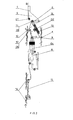
- Fig. 2 presents the view of the mechanism with the door open from above
- Fig. 3 presents the mechanism fragment with the door closed from above
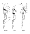
- Fig. 4a, 4b, and 4c present the following positions of the mechanism: closed door, semi-closed door, and open door.
- the height h1 of the door 4 is greater than the height h2 of the locker 1.
- the element system of the motor of door 4 is embedded in the top partition 2 of the locker 1 and is composed of the following: servomotor 8, joint 9, and two-armed rocker 10, with the interactive arm with the driving pin 11.
- the driving pin 11 interacts with the grooved cam 6 executed in the exterior arm 5, which is stiffly fixed to the door 4.
- the cam 6 is shaped as a rounded broken line, the longitudinal axis O5 of which - which connects its block end kb and opening end ko - is directed perpendicularly to the plane of the door 4.
- the length I of the cam 6 is greater than the pitch s of the servomotor 8, and contains the closing socket 7, which is marked with the pressure surfaces Pn inclined towards each other and the surface of the block end Pb, near the end of block end kb, which is located farther than the hinge axis O1.
- the pressure surface With the servomotor 8 in the extreme back position "a" and closed “A” door, the pressure surface is oriented so that the straight line "n" perpendicular to it passes through the extension axis of the cam O2.
- This geometry of the force system present during a break-in attempt prevents the opening of the door 4 from the outside.
- the axes of the block end kb and the opening end ko in the cam 6 are inclined towards the hinge axis 01 and are situated in opposite directions. In the middle segment, the groove of cam 6 is marked on the side of the hinge axis 01 with an arched opening surface and opposite closing surface pz.
- the electromechanical servomotor 8 is fixed on the top partition 2 with its axis O4 perpendicular to the door casing 3. In the position of the servomotor 8 extremely back "a” and closed “A” door 4, the projection of the joints of the kinematic system on the plane of the door casing 3 situates the following in order: the driving pin axis O3, the hinge axis O1, the coupling socket axis O6 in the cam 10, the servomotor axis O4, and the rocker extension axis 2.
- the driving pin 11 of the rocker 10 is weighed down with the tension spring 13, the other end of which is fixed in point "z", which is located so that the axis of the tension spring 13 runs along the rocker extension axis O2 on the side of the servomotor 8.
- the axis of the tension spring 13 runs along the rocker extension axis O2 on the side of the door casing 3.
- the mechanism is equipped with the hall effect sensor 14, which initiates a signal in the closed "A" position of the door 4.
Landscapes
- Engineering & Computer Science (AREA)
- Food Science & Technology (AREA)
- Power-Operated Mechanisms For Wings (AREA)
Priority Applications (1)
| Application Number | Priority Date | Filing Date | Title |
|---|---|---|---|
| PCT/PL2013/000127 WO2014209139A1 (fr) | 2013-06-27 | 2013-10-04 | Mécanisme d'activation de la porte d'un casier dans une armoire destiné à envoyer et recevoir du courrier, en particulier des lettres |
Applications Claiming Priority (1)
| Application Number | Priority Date | Filing Date | Title |
|---|---|---|---|
| PL404473A PL221479B1 (pl) | 2013-06-27 | 2013-06-27 | Mechanizm uruchamiania drzwiczek skrytki w szafie odbiorczo-nadawczej przesyłek, zwłaszcza listowych |
Publications (1)
| Publication Number | Publication Date |
|---|---|
| EP2818082A1 true EP2818082A1 (fr) | 2014-12-31 |
Family
ID=49356155
Family Applications (1)
| Application Number | Title | Priority Date | Filing Date |
|---|---|---|---|
| EP13004721.0A Withdrawn EP2818082A1 (fr) | 2013-06-27 | 2013-09-30 | Mécanisme d'activation de la porte d'un verrou dans l'armoire permettant d'envoyer et de recevoir du courrier, particulièrement des lettres |
Country Status (3)
| Country | Link |
|---|---|
| EP (1) | EP2818082A1 (fr) |
| PL (1) | PL221479B1 (fr) |
| WO (1) | WO2014209139A1 (fr) |
Citations (7)
| Publication number | Priority date | Publication date | Assignee | Title |
|---|---|---|---|---|
| US5566991A (en) * | 1994-10-28 | 1996-10-22 | R R Brink Locking Systems, Inc. | Lock with cam operated mechanism |
| FR2770117A1 (fr) * | 1997-10-29 | 1999-04-30 | Electrobox | Dispositif de verrouillage-deverrouillage electrique individuel et collectif d'un ensemble de boites aux lettres |
| EP1066783A1 (fr) * | 1999-07-07 | 2001-01-10 | Hitaction S.A. | Bloc de boítes aux lettres à ouverture totale |
| FR2845718A1 (fr) | 2002-10-10 | 2004-04-16 | Laperche Sa | Serrure et huisserie correspondante |
| DE20302161U1 (de) * | 2003-02-10 | 2004-06-17 | Dewert Antriebs- Und Systemtechnik Gmbh & Co. Kg | Antriebsbaueinheit |
| DE202004008071U1 (de) | 2004-05-14 | 2004-08-19 | Erwin Renz Metallwarenfabrik Gmbh & Co. Kg | Verschließbares Aufbewahrungsbehältnis |
| FR2941732A1 (fr) | 2009-01-30 | 2010-08-06 | Decayeux Ets | Installation de porte collective |
-
2013
- 2013-06-27 PL PL404473A patent/PL221479B1/pl unknown
- 2013-09-30 EP EP13004721.0A patent/EP2818082A1/fr not_active Withdrawn
- 2013-10-04 WO PCT/PL2013/000127 patent/WO2014209139A1/fr not_active Ceased
Patent Citations (7)
| Publication number | Priority date | Publication date | Assignee | Title |
|---|---|---|---|---|
| US5566991A (en) * | 1994-10-28 | 1996-10-22 | R R Brink Locking Systems, Inc. | Lock with cam operated mechanism |
| FR2770117A1 (fr) * | 1997-10-29 | 1999-04-30 | Electrobox | Dispositif de verrouillage-deverrouillage electrique individuel et collectif d'un ensemble de boites aux lettres |
| EP1066783A1 (fr) * | 1999-07-07 | 2001-01-10 | Hitaction S.A. | Bloc de boítes aux lettres à ouverture totale |
| FR2845718A1 (fr) | 2002-10-10 | 2004-04-16 | Laperche Sa | Serrure et huisserie correspondante |
| DE20302161U1 (de) * | 2003-02-10 | 2004-06-17 | Dewert Antriebs- Und Systemtechnik Gmbh & Co. Kg | Antriebsbaueinheit |
| DE202004008071U1 (de) | 2004-05-14 | 2004-08-19 | Erwin Renz Metallwarenfabrik Gmbh & Co. Kg | Verschließbares Aufbewahrungsbehältnis |
| FR2941732A1 (fr) | 2009-01-30 | 2010-08-06 | Decayeux Ets | Installation de porte collective |
Also Published As
| Publication number | Publication date |
|---|---|
| PL221479B1 (pl) | 2016-04-29 |
| WO2014209139A1 (fr) | 2014-12-31 |
| PL404473A1 (pl) | 2015-01-05 |
Similar Documents
| Publication | Publication Date | Title |
|---|---|---|
| EP2784251B1 (fr) | Serrure de véhicule automobile | |
| CN104420741B (zh) | 机动车锁件 | |
| EP2784252B1 (fr) | Serrure de véhicule automobile | |
| EP3260636A1 (fr) | Appareil de verrouillage de portière d'automobile | |
| KR20190141182A (ko) | 차량용 록 | |
| US20190234122A1 (en) | Handle device with a surface-flush handle | |
| CN107575085B (zh) | 能够调整门边距的放大门插锁及具备其的数码门锁装置 | |
| US9732544B2 (en) | Motor vehicle lock | |
| KR102165338B1 (ko) | 플랩 또는 도어용 록 | |
| EP3260635A1 (fr) | Appareil de verrouillage de portière d'automobile | |
| EP1721802A1 (fr) | Dispositif d'ouverture et de fermeture avec un dispositif de verrouillage | |
| US11466499B2 (en) | Manipulator for an access member, access member comprising the manipulator, system and method | |
| CN204081787U (zh) | 用于可动的家具部件的驱动装置和家具 | |
| EP2851494A2 (fr) | Serrure de véhicule automobile | |
| CN109415912A (zh) | 用于机动车的锁闭装置 | |
| CN108699873B (zh) | 用于连接可滑动且可翻转的扇的装配总成 | |
| WO2003024730A3 (fr) | Toit de vehicule ouvrant | |
| EP2818082A1 (fr) | Mécanisme d'activation de la porte d'un verrou dans l'armoire permettant d'envoyer et de recevoir du courrier, particulièrement des lettres | |
| US10508475B2 (en) | Motor vehicle lock | |
| EP3702560B1 (fr) | Mécanisme de fonctionnement de clé d'automobile | |
| US10501983B2 (en) | Electromagnetic door opener | |
| KR20150009970A (ko) | 플랩 또는 도어용 록 | |
| US11648829B2 (en) | Assembly and method for moving a cover | |
| EP2412902B1 (fr) | Porte sectionnelle avec porte d'entrée dotée d'un système de fermeture | |
| EP2843161B1 (fr) | Disposittif de verrouillage des casiers à courrier, notamment pour des lettres |
Legal Events
| Date | Code | Title | Description |
|---|---|---|---|
| PUAI | Public reference made under article 153(3) epc to a published international application that has entered the european phase |
Free format text: ORIGINAL CODE: 0009012 |
|
| 17P | Request for examination filed |
Effective date: 20130930 |
|
| AK | Designated contracting states |
Kind code of ref document: A1 Designated state(s): AL AT BE BG CH CY CZ DE DK EE ES FI FR GB GR HR HU IE IS IT LI LT LU LV MC MK MT NL NO PL PT RO RS SE SI SK SM TR |
|
| AX | Request for extension of the european patent |
Extension state: BA ME |
|
| STAA | Information on the status of an ep patent application or granted ep patent |
Free format text: STATUS: THE APPLICATION HAS BEEN WITHDRAWN |
|
| 18W | Application withdrawn |
Effective date: 20150407 |