EP2818092A1 - Lave-vaisselle - Google Patents
Lave-vaisselle Download PDFInfo
- Publication number
- EP2818092A1 EP2818092A1 EP14171655.5A EP14171655A EP2818092A1 EP 2818092 A1 EP2818092 A1 EP 2818092A1 EP 14171655 A EP14171655 A EP 14171655A EP 2818092 A1 EP2818092 A1 EP 2818092A1
- Authority
- EP
- European Patent Office
- Prior art keywords
- basket
- plate
- unit
- case
- auxiliary
- Prior art date
- Legal status (The legal status is an assumption and is not a legal conclusion. Google has not performed a legal analysis and makes no representation as to the accuracy of the status listed.)
- Granted
Links
Images





Classifications
-
- A—HUMAN NECESSITIES
- A47—FURNITURE; DOMESTIC ARTICLES OR APPLIANCES; COFFEE MILLS; SPICE MILLS; SUCTION CLEANERS IN GENERAL
- A47L—DOMESTIC WASHING OR CLEANING; SUCTION CLEANERS IN GENERAL
- A47L15/00—Washing or rinsing machines for crockery or tableware
- A47L15/42—Details
- A47L15/50—Racks ; Baskets
- A47L15/507—Arrangements for extracting racks, e.g. roller supports
-
- A—HUMAN NECESSITIES
- A47—FURNITURE; DOMESTIC ARTICLES OR APPLIANCES; COFFEE MILLS; SPICE MILLS; SUCTION CLEANERS IN GENERAL
- A47L—DOMESTIC WASHING OR CLEANING; SUCTION CLEANERS IN GENERAL
- A47L15/00—Washing or rinsing machines for crockery or tableware
- A47L15/42—Details
- A47L15/50—Racks ; Baskets
- A47L15/506—Arrangements for lifting racks for loading or unloading purposes
-
- A—HUMAN NECESSITIES
- A47—FURNITURE; DOMESTIC ARTICLES OR APPLIANCES; COFFEE MILLS; SPICE MILLS; SUCTION CLEANERS IN GENERAL
- A47L—DOMESTIC WASHING OR CLEANING; SUCTION CLEANERS IN GENERAL
- A47L15/00—Washing or rinsing machines for crockery or tableware
-
- A—HUMAN NECESSITIES
- A47—FURNITURE; DOMESTIC ARTICLES OR APPLIANCES; COFFEE MILLS; SPICE MILLS; SUCTION CLEANERS IN GENERAL
- A47L—DOMESTIC WASHING OR CLEANING; SUCTION CLEANERS IN GENERAL
- A47L15/00—Washing or rinsing machines for crockery or tableware
- A47L15/42—Details
- A47L15/50—Racks ; Baskets
Definitions
- the following description relates to a dishwasher having an improved structure by which a basket is easily withdrawn.
- a dishwasher is a device spraying high pressure wash water onto one or more objected to be washed such as dishes to wash the objects and typically undergoes a preliminary washing process, for example, a main washing process, a rinsing process, and a drying process.
- Dishwashing is performed by spraying only wash water without detergent to wash contaminants off of the objects in the preliminary washing process, and then simultaneously inserting detergent using a detergent supply unit while spraying wash water in the main washing process.
- the dishwasher typically includes a cabinet provided with a washing bath therein, a pump to generate a wash water pressure, a basket which receives objects to be washed and is installed movably in a forward and backward direction within the washing bath, spray units to spray wash water onto the basket, a connection passage through which the pump and the spray units are connected, and a passage switching valve to selectively move wash water from the pump to the multiple spray units, thereby washing the objects to be washed by the wash water sprayed from the spray units.
- the basket includes an upper basket provided at an upper portion of the washing bath and a lower basket provided at a lower portion thereof.
- the lower basket Since the lower basket has a structure to store the objects to be washed in a state of being arranged at the lower portion of the washing bath and moving forward, the objects may be inserted into or withdrawn from the lower basket in a state in which a user bends down. Therefore, this may very inconvenient for the user and may not be good for the user's health.
- the lower basket in terms of a structure of the dishwasher, the lower basket is relatively larger in size than the upper basket and heavy objects are received in the lower basket and washed. Accordingly, it may be hard to insert or withdraw these objects into or from the lower basket.
- a dishwasher having a structure capable of improving user experience when a basket is withdrawn. It is another aspect of the present disclosure to provide a dishwasher having an improved structure capable of stably storing objects to be washed such as dishes by stably and fixedly maintaining a basket in a state in which the basket is lifted.
- a dishwasher includes a case, a basket arranged within the case to receive objects to be washed, a rail provided on an inner wall of the case in order to guide the basket such that the basket is withdrawn forward of the case, a link unit mounted to the basket to lift the basket, and an auxiliary unit connected to the link unit such that lifting force acts on the basket based on a position of the basket.
- the link unit may include a first plate coupled to a plurality of first rollers moving forward of the case along the rail, a second plate provided, at an end portion thereof, with a basket holder portion coupled to the basket, a first rotation shaft being formed at a position at which the first plate and the second plate are coupled, and a third plate coupled to the second plate by a fixing member so as to be rotated together with the second plate, a second rotation shaft being formed at a position at which the first plate and the third plate are coupled.
- the dishwasher may further include an auxiliary rail installed on the inner wall of the case in parallel with the rail, the auxiliary rail having a front end portion positioned farther rearward than that of a support.
- the third plate may have a second roller, which moves forward of the case along the auxiliary rail and is formed at an end portion thereof in a direction away from the second rotation shaft.
- the third plate may be rotated about the second rotation shaft toward the front of the case in order to lift the basket when the second roller is decoupled from the auxiliary rail toward the front of the case such that the link unit lifts the basket at a distal end portion of the rail withdrawn outward of the case.
- the dishwasher may further include a first coupling shaft by which the auxiliary unit is mounted to the third plat, and a second coupling shaft by which the auxiliary unit is mounted to the first plate, wherein when the first coupling shaft is positioned below a reference line defined by the second coupling shaft and the second rotation shaft, the basket may be lifted as the third plate is rotated about the second rotation shaft toward the front of the case.
- the dishwasher may further include a lever unit which is provided between the auxiliary unit and the third plate and is mounted to the first plate, the lever unit being moved down to a position reaching the auxiliary rail when the third plate is rotated about the second rotation shaft toward the front of the case.
- the lever unit When external force is applied to the lifted basket toward the rear of the case, the lever unit may contact a front surface portion of the auxiliary rail in order to prevent the basket from moving rearward of the case.
- the dishwasher may further include a locking unit mounted outside the basket holder portion so as to fix or secure the lifted basket.
- the locking unit may be mounted, at one end portion thereof, outside the basket holder portion, and be provided, at the other end portion thereof, with a fixing groove opened in a direction opposite to a withdrawal direction of the basket such that the fixing groove engages with a fixing portion, which is formed at the third plate and protrudes in a direction away from the basket.
- the dishwasher may further include a release unit, which is connected to the locking unit and moves the locking unit in the withdrawal direction of the basket, thereby allowing the fixing groove to be moved away from the fixing portion.
- the fixing portion may be decoupled from the fixing groove when the release unit is operated, thereby allowing the third plate to enter a state rotatable about the second rotation shaft, and when external force is applied to the basket, the basket may drop or moves downward until a first coupling shaft is positioned above a reference line defined by a second coupling shaft and the second rotation shaft.
- the auxiliary unit may use at least one of expansion forces of a gas, a fluid, and a spring compressed within a cylinder, in order to relieve vibration or shock applied to the basket.
- the auxiliary unit may be configured such that at least one auxiliary unit is provided at the link unit.
- a dishwasher in accordance with another aspect of the present disclosure, includes a case, a basket arranged within the case to receive objects to be washed, rails which engage with supports installed at both inner walls of the case to move forward and rearward of the case, in order to guide the basket such that the basket is withdrawn forward of the case, a first link unit and a second link unit which are mounted to both side surface portions of the basket so as to lift the basket, and a first auxiliary unit and a second auxiliary unit which are connected to the first link unit and the second link unit such that lifting force acts on the basket based on a position of the basket.
- Each of the first link unit and the second link unit may include a first plate coupled to a plurality of first rollers moving forward of the case along the corresponding rail, a second plate provided, at an end portion thereof, with a basket holder portion coupled to the basket, a first rotation shaft being formed at a position at which the first plate and the second plate are coupled, and a third plate coupled to the second plate so as to be rotated together with the second plate, a second rotation shaft being formed at a position at which the first plate and the third plate are coupled, and when a first coupling shaft by which the first auxiliary unit or the second auxiliary unit is mounted to the third plate is positioned below a reference line defined by a second coupling shaft by which the first auxiliary unit or the second auxiliary unit is mounted to the first plate and the second rotation shaft, the basket may be lifted as the third plate is rotated about the second rotation shaft toward the front of the case.
- the first coupling shaft moving closer to the reference line may differ according to the first auxiliary unit and the second auxiliary unit.
- the dishwasher may further include auxiliary rails installed at both inner walls of the case in parallel with the rails, the auxiliary rails having front ends positioned farther rearward than those of the supports.
- the dishwasher may further include a lever unit which is provided between the first or second auxiliary unit and the third plate and is mounted to the first plate, the lever unit being moved down to a position reaching the corresponding auxiliary rail when the third plate is rotated about the second rotation shaft toward the front of the case.
- the dishwasher may further include a locking unit, which is mounted, at one end portion thereof, outside the basket holder portion so as to fix or secure the lifted basket, and is provided, at the other end portion thereof, with a fixing groove opened in a direction opposite to a withdrawal direction of the basket such that the fixing groove engages with a fixing portion, which is formed at the third plate and protrudes in a direction away from the basket.
- a locking unit which is mounted, at one end portion thereof, outside the basket holder portion so as to fix or secure the lifted basket, and is provided, at the other end portion thereof, with a fixing groove opened in a direction opposite to a withdrawal direction of the basket such that the fixing groove engages with a fixing portion, which is formed at the third plate and protrudes in a direction away from the basket.
- the dishwasher may further include a release unit, which is connected to the locking unit by a connection member and has a shape protruding toward a front upper end portion of the basket, wherein when the release unit is operated, the fixing groove may be pulled in the withdrawal direction of the basket by the connection member so as to be away from the fixing portion.
- a release unit which is connected to the locking unit by a connection member and has a shape protruding toward a front upper end portion of the basket, wherein when the release unit is operated, the fixing groove may be pulled in the withdrawal direction of the basket by the connection member so as to be away from the fixing portion.
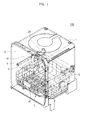
- FIG. 1 is a perspective view illustrating a configuration of a dishwasher according to an embodiment of the present disclosure.
- a dishwasher 100 includes a case 1 defining an external appearance thereof and a washing bath 2 provided inside the case 1 to perform dishwashing.
- the washing bath 2 is provided, at a lower portion thereof, with a sump (not shown) to store wash water.
- the case 1 is opened at a front surface portion thereof so that one or more objects to be washed such as dishes may be received in or withdrawn from the washing bath 2, and a door (not shown) is installed to the front surface portion of the case 1 so as to open and close the washing bath 2.
- the door is hinge-coupled to and pivoted about a front lower portion of the case 1 so that the washing bath 2 is opened and closed.
- a plurality of of baskets 3 provided with storage portions, upper portions of which are opened to receive the objects, are respectively installed to the upper and lower portions of the washing bath 2 so as to be movable in a forward and backward direction.
- Each of the baskets 3 is withdrawn or inserted through the opened front surface portion of the case 1 by at least one rail 4 to slidably move the basket 3.
- the rail 4 engages with a support 5 fixed to an inner wall of the case 1, and may move along the inner wall of the case 1 in the forward and backward direction by at least one roller (not shown) provided between the rail 4 and the support 5.
- the basket 3 is formed by wires 37 arranged in a lattice form such that the dishes received in the basket 3 may be washed by being exposed outward thereof.
- a spray unit (not shown) to spray wash water onto the basket 3 is mounted on at least one surface portion of the washing bath 2.
- the spray unit may include an upper spray unit and a lower spray unit to respectively spray water onto the upper and lower baskets, but the present disclosure is not limited thereto.
- the washing bath 2 may be provided with link units 10, auxiliary units 20, and auxiliary rails 6.
- the link units 10 may be fixed to an outer portion of the basket 3 and lift the basket 3.
- the auxiliary units 20 may be connected to the corresponding link unit 10 such that lifting force acts on the basket 3 based on a position of the basket 3.
- the auxiliary rails 6 may prevent the basket 3 from being lifted within the case 1 in a state of being improperly withdrawn, and may be installed on the inner wall of the case 1 in parallel with the rail 4.
- the auxiliary rail 6 may have a shorter length than the support 5 in the front of the case 1. In other words, the auxiliary rail 6 may have a front end portion positioned farther rearward of the case 1 than that of the support 5.
- the auxiliary rail 6 may be formed in a bead shape recessed toward the inside of the case 1 as well as being a separate member.
- FIG. 2 is a perspective view illustrating a basket holder portion in the dishwasher according to an embodiment of the present disclosure.
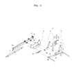
- FIG. 3 is an exploded perspective view illustrating a partial configuration of the dishwasher according to an embodiment of the present disclosure.
- the link unit 10 may include a first plate 11, a second plate 12, and a third plate 13.
- the first plate 11 is coupled to a plurality of first rollers 14 moving forward of the case 1 along the rail 4, and thus may move in a longitudinal direction of the rail 4.
- the rail 4 may be provided, at end portions thereof, with stoppers 15 so as not to decouple the plurality of first rollers 14.
- the stoppers 15 may include a first stopper 15a and a second stopper 15b.
- a first stopper 15a formed at an end portion of the rail 4 located forward of the case 1, may have a projection portion 16 bent in a withdrawal direction of the basket 3 to engage with the corresponding first roller 14.
- a second stopper 15b is formed at the other end portion of the rail 4, and the rail 4 may move forward of the case 1 until the second stopper 15b reaches an end portion of the support 5.
- the first plate 11 may be formed, on a surface portion thereof, with a plurality of fixing holes 17 corresponding to positions and numbers of the plurality of first rollers 14 such that the first plate 11 may be coupled to the plurality of first rollers 14.
- the second plate 12 may be mounted to the first plate 11, and may be provided, at one end portion thereof, with a basket holder portion 30 coupled to the basket 3.
- the basket holder portion 30 may include a first cover 31, a second cover 32, and a third cover 33.
- the first cover 31 may be formed with a plurality of protrusion portions 34 protruding toward the inner wall of the case 1, and the second cover 32 may be formed with a plurality of first mounting holes 35 corresponding to the plurality of protrusion portions 34.
- the third cover 33 may be formed with a plurality of second mounting holes 36 corresponding to the first mounting holes 35 so as to fix the first and second covers 31 and 32.
- the plurality of protrusion portions 34 and the plurality of first mounting holes 35 face each other while interposing the lattice shaped wires 37 configuring the basket 3 therebetween.
- the first cover 31 arranged at an inner portion of the basket 3 and the second cover 32 arranged at an outer portion of the basket 3 are mounted to each other inside the basket 3.
- the third cover 33 is arranged outside the second cover 32, and fixing members (not shown) pass through the plurality of second mounting holes 36 arranged at the third cover 33 and the plurality of first mounting holes 35 arranged at the second cover 32 and are then inserted into the plurality of protrusion portions 34 arranged at the first cover 31, respectively. Consequently, the first cover 31 and the second cover 32 are fixed while interposing the wires 37 of the basket 3 therebetween.
- a first rotation shaft 38 may be formed at a position at which the second and first plates 12 and 11 are coupled.
- the third plate 13 is coupled to the first plate 11, and a second rotation shaft 39 may be formed at a position at which the third and first plates 13 and 11 are coupled.
- One end portion of the third plate 33 is positioned between the second and third covers 32 and 33 of the basket holder portion 30, and is fixed to the third cover 33 by a fixing member 73.
- the second and third plates 12 and 13 may share the load of the basket 3 mounted to the basket holder portion 30.
- the third plate 13 may be coupled to the second plate 12 by a fixing member 40 provided between the second and third plates 12 and 13.
- the second plate 12 is rotatable about the first rotation shaft 38
- the third plate 13 is rotatable about the second rotation shaft 39.
- the second and third plates 12 and 13 may be rotated together about the first and second rotation shafts 38 and 39 since the second and third plates 12 and 13 are coupled by the fixing member 40.
- the third plate 13 may be formed, at an end portion thereof, with a second roller 41.
- the second roller 41 may be provided at the end portion of the third plate 13 in a direction away from the second rotation shaft 39, and may forwardly and backwardly move along the auxiliary rail 6 in a longitudinal direction thereof.
- At least one second roller 41 may be provided.
- the auxiliary unit 20 may be mounted to the third plate 13.
- the auxiliary unit 20 prevents vibration or shock from being applied to the basket 3 and the objects received in the basket 3 when the basket 3 is lifted or dropped.
- the auxiliary unit 20 may be mounted, at one end portion thereof, to the third plate 13, and be mounted, at the other end portion thereof, to the first plate 11.
- a first coupling shaft 21 is formed by mounting of the auxiliary unit 20 to the third plate 13, and a second coupling shaft 22 is formed by mounting of the auxiliary unit 20 to the first plate 11.
- the first coupling shaft 21 and the second coupling shaft 22 may be integrated to the auxiliary unit 20.
- the first coupling shaft 21 may be provided at one end portion of the auxiliary unit 20, and the second coupling shaft 22 may be provided at the other end portion of the auxiliary unit 20.
- the auxiliary unit 20 may use at least one of expansion force of a gas, a fluid, and a spring compressed within a cylinder.
- At least one auxiliary unit 20 may be provided at the link unit 10.
- the first plate 11 may be mounted with a lever unit 50.
- the lever unit 50 prevents the basket 3 from moving rearward of the case 1 when external force is applied to the lifted basket 3 toward the rear of the case 1.
- the lever unit 50 fixed to the first plate 11 may be positioned between the auxiliary unit 20 and the third plate 13.
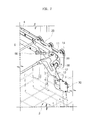
- FIG. 4 is a perspective view illustrating a state in which the basket is withdrawn from the dishwasher according to an embodiment of the present disclosure.
- FIG. 5 is a perspective view illustrating a state in which the basket is lifted in the dishwasher according to an embodiment of the present disclosure.
- the basket 3 may be withdrawn outward of the case 1 along the rail 4.
- the plurality of first rollers 14 coupled to the first plate 11 move forward of the case 1 along the rail 4, and the second roller 41 coupled to the third plate 13 moves forward of the case 1 along the auxiliary rail 6.
- the plurality of first rollers 14 move forward of the case 1 until the first rollers 14 are caught by the projection portion 16 formed at the first stopper 15a provided at one end portion of the rail.
- the second roller 41 is decoupled from a position at which the auxiliary rail 6 ends in a longitudinal direction thereof.
- the auxiliary rail 6 may have a distal end portion which is at a position equal to or shorter than that of the support 5 in the front portion of the case 1.
- the rail 4 may move forward of the case 1 until the second stopper 15b provided at the other end portion of the rail 4 is caught by the end portion of the support 5.
- the second roller 41 may already be decoupled from the auxiliary rail 6.
- the basket 3 may be lifted as the third plate 13 is rotated about the second rotation shaft 39 toward the front portion of the case 1.
- the respective link units 10 and the respective auxiliary units 20 may be provided at both inner walls of the case 1.
- the link units 10 provided at both inner walls of the case 1 are respectively referred to as a first link unit 10a and a second link unit 10b.
- the auxiliary unit 20 mounted to the first link unit 10a is referred to as a first auxiliary unit 20a and the auxiliary unit 20 mounted to the second link unit 10b is referred to as a second auxiliary unit (not shown).
- the first auxiliary unit 20a and the second auxiliary unit (not shown) are connected to each other by a first shaft 51, and a third plate 13a of the first link unit 10a is connected to a third plate 13b of the second link unit 10b by a second shaft 52.
- the first coupling shaft 21 rapidly moves upward or downward of the reference line 53 as the first coupling shaft 21 moves closer to the reference line 53. Therefore, a point of time to lift the basket 3 may be advanced, whereas greater force may be needed to lift the basket 3.
- the first coupling shaft 21 moving closer to the reference line 53 may differ according to the first auxiliary unit 20a and the second auxiliary unit (not shown).
- first auxiliary unit 20a and the second auxiliary unit may have different expansion forces from each other.
- FIG. 6 is a perspective view illustrating a state in which the second roller is decoupled from the auxiliary rail in the dishwasher according to an embodiment of the present disclosure.
- FIG. 7 is a perspective view illustrating a state in which external force is applied to the lifted basket toward the rear of the case in the dishwasher according to an embodiment of the present disclosure.
- the second roller 41 is decoupled from the auxiliary rail 6, and thus the third plate 13 enters a state rotatable about the second rotation shaft 39 toward the front of the case 1.
- the second and third plates 12 and 13 are rotated about the first and second rotation shafts 38 and 39 toward the front portion of the case 1 while the first coupling shaft 21 moves downward of the reference line 53, thereby allowing the basket 3 mounted to the basket holder portion 30 to be lifted.
- the lever unit 50 mounted to the first plate 11 may be positioned between the rail 4 and the auxiliary rail 6 when the second roller 41 moves along the auxiliary rail 6, and may be moved down to a position reaching the auxiliary rail 6 when the second roller 41 is decoupled from the auxiliary rail 6 and is rotated about the second rotation shaft 39 toward the front portion of the case 1.
- the lever unit 50 may contact a front surface portion of the auxiliary rail 6 in order to prevent the basket 3 from moving rearward of the case 1.
- FIG. 8 is a perspective view illustrating a state of fastening a locking unit in the dishwasher according to an embodiment of the present disclosure while a partial configuration thereof is omitted.
- FIG. 9 is a perspective view illustrating a state of releasing the locking unit in the dishwasher according to an embodiment of the present disclosure while a partial configuration thereof is omitted.
- FIG. 10 is a perspective view illustrating a release unit in the dishwasher according to an embodiment of the present disclosure.
- the dishwasher 100 may include a locking unit 60 and a release unit 70.
- the locking unit 60 fixes or secures the lifted basket 3, and may be mounted outer portion of the basket holder portion 30.
- the locking unit 60 may be mounted, at one end portion thereof, to the third cover 33 of the basket holder portion 30, and may be provided, at the other end portion thereof, with a fixing groove 61 opened in a direction opposite to the withdrawal direction of the basket 3.
- the fixing groove 61 engages with a fixing portion 62, which is formed at the third plate 13 and protrudes in a direction away from the basket 3, thereby enabling the lifted basket 3 to be fixed or secured.
- the release unit 70 may move the locking unit 70 in the left and right directions.
- the release unit 70 is connected to the locking unit and moves the locking unit 70 in the withdrawal direction of the basket 3, thereby allowing the fixing groove 61 to be moved away from the fixing portion 62.
- the locking units 60 may be respectively installed to the link units 10 mounted at both inner wall of the case 1.
- the release unit 70 may be connected to the locking unit 60 by a connection member 71, and may have a shape protruding toward a front upper end portion of the basket 3.
- connection member 71 is connected to the locking unit 60 by passing through a connection hole 72 provided at a side lower portion of the basket 3 from the release unit 70.
- connection member 71 pulls the locking unit 60 in the withdrawal direction of the basket 3 when the release unit 70 is pushed, and thus the third plate 13 enters a movable state.
- the release unit 70 may be realized in the form of a lever or a button.
- the locking unit 60 may be released by manually moving the same.
- the fixing portion 62 is decoupled from the fixing groove 61 when the release unit 70 is operated, thereby enabling the third plate 13 to enter a state rotatable about the second rotation shaft 39.
- the first coupling shaft 21 moves upward of the reference line 53 when external force is applied to the basket 3, thereby enabling the basket 3 to drop or move downward.
- a user may withdraw a lower basket without bending down and store objects to be washed by providing a lifting unit in a dishwasher.
Landscapes
- Washing And Drying Of Tableware (AREA)
Applications Claiming Priority (1)
| Application Number | Priority Date | Filing Date | Title |
|---|---|---|---|
| KR1020130074299A KR102002419B1 (ko) | 2013-06-27 | 2013-06-27 | 식기세척기 |
Publications (2)
| Publication Number | Publication Date |
|---|---|
| EP2818092A1 true EP2818092A1 (fr) | 2014-12-31 |
| EP2818092B1 EP2818092B1 (fr) | 2022-02-16 |
Family
ID=50896188
Family Applications (1)
| Application Number | Title | Priority Date | Filing Date |
|---|---|---|---|
| EP14171655.5A Not-in-force EP2818092B1 (fr) | 2013-06-27 | 2014-06-09 | Lave-vaisselle |
Country Status (3)
| Country | Link |
|---|---|
| US (1) | US9549660B2 (fr) |
| EP (1) | EP2818092B1 (fr) |
| KR (1) | KR102002419B1 (fr) |
Cited By (16)
| Publication number | Priority date | Publication date | Assignee | Title |
|---|---|---|---|---|
| EP3085294A1 (fr) | 2015-04-24 | 2016-10-26 | BSH Hausgeräte GmbH | Dispositif de levage et lave-vaisselle |
| DE102015207564A1 (de) | 2015-04-24 | 2016-10-27 | BSH Hausgeräte GmbH | Hebevorrichtung und Geschirrspülmaschine |
| EP3092936A1 (fr) | 2015-05-11 | 2016-11-16 | BSH Hausgeräte GmbH | Lave-vaisselle |
| DE102015208909A1 (de) | 2015-05-13 | 2016-11-17 | BSH Hausgeräte GmbH | Geschirrspülmaschine |
| DE102015208654A1 (de) | 2015-05-11 | 2016-11-17 | BSH Hausgeräte GmbH | Hebevorrichtung und Geschirrspülmaschine |
| WO2016188554A1 (fr) * | 2015-05-22 | 2016-12-01 | Electrolux Appliances Aktiebolag | Mécanisme de déverrouillage d'un panier inférieur d'un lave-vaisselle verrouillé à une position supérieure |
| DE102015211362A1 (de) | 2015-06-19 | 2016-12-22 | BSH Hausgeräte GmbH | Hebevorrichtung und Geschirrspülmaschine |
| DE102015218271A1 (de) | 2015-09-23 | 2017-03-23 | BSH Hausgeräte GmbH | Hebevorrichtung und Geschirrspülmaschine |
| DE102015226559A1 (de) | 2015-12-22 | 2017-06-22 | BSH Hausgeräte GmbH | Hebevorrichtung, Verfahren zum Betreiben einer Hebevorrichtung und Geschirrspülmaschine |
| DE102016201727A1 (de) | 2016-02-04 | 2017-08-10 | BSH Hausgeräte GmbH | Hebevorrichtung, Verfahren zum Betreiben einer Hebevorrichtung und Geschirrspülmaschine |
| DE102016209384A1 (de) | 2016-05-31 | 2017-11-30 | BSH Hausgeräte GmbH | Nachrüstbare Hebevorrichtung und Geschirrspülmaschine |
| DE102016217975A1 (de) | 2016-09-20 | 2018-03-22 | BSH Hausgeräte GmbH | Haushaltsgeschirrspülmaschine |
| DE102016225807A1 (de) | 2016-12-21 | 2018-06-21 | BSH Hausgeräte GmbH | Haushaltsgeschirrspülmaschine |
| DE102017211203A1 (de) | 2017-06-30 | 2019-01-03 | BSH Hausgeräte GmbH | Hebesystem für eine Haushaltsgeschirrspülmaschine oder ein Möbel |
| DE102018132800A1 (de) * | 2018-05-15 | 2019-11-21 | Paul Hettich Gmbh & Co. Kg | Schiebe-Schwenkmechanik einer Ablage eines Möbels oder Haushaltsgerätes und Möbel oder Haushaltsgerät |
| US10638913B2 (en) | 2014-12-22 | 2020-05-05 | BSH Hausgeräte GmbH | Lower rack for a domestic dishwasher having a lower-rack raising means |
Families Citing this family (15)
| Publication number | Priority date | Publication date | Assignee | Title |
|---|---|---|---|---|
| DE102012107993A1 (de) * | 2012-08-29 | 2014-03-06 | Paul Hettich Gmbh & Co. Kg | Schiebe-Schwenkmechanik einer Ablage eines Möbels, Möbel und Geschirrspüler |
| DE102014107962A1 (de) * | 2014-06-05 | 2015-12-17 | Paul Hettich Gmbh & Co. Kg | Schiebe-Schwenkmechanik einer Ablage eines Möbels oder Haushaltsgerätes, Möbel und Haushaltsgerät |
| DE102014107959A1 (de) * | 2014-06-05 | 2015-12-17 | Paul Hettich Gmbh & Co. Kg | Schiebe-Schwenkmechanik einer Ablage eines Möbels oder Haushaltsgerätes, Möbel und Haushaltsgerät |
| DE102015208645A1 (de) * | 2015-05-11 | 2016-11-17 | BSH Hausgeräte GmbH | Hebevorrichtung und Geschirrspülmaschine |
| DE102015211495B4 (de) * | 2015-06-22 | 2017-12-14 | BSH Hausgeräte GmbH | Hebevorrichtung und Geschirrspülmaschine |
| CN106551670B (zh) * | 2015-09-24 | 2019-11-15 | Lg电子株式会社 | 洗碗机 |
| US10729305B2 (en) * | 2016-03-18 | 2020-08-04 | Samsung Electronics Co., Ltd. | Collapsible dish rack for dishwasher |
| KR101902105B1 (ko) * | 2017-03-03 | 2018-09-27 | 엘지전자 주식회사 | 조리 기기 |
| CN108478160B (zh) * | 2018-05-09 | 2024-02-02 | 火星人厨具股份有限公司 | 一种厨具中升降碗篮的升降锁死机构 |
| DE102019107385A1 (de) * | 2019-03-22 | 2020-09-24 | Paul Hettich Gmbh & Co. Kg | Schiebe-Schwenkmechanik für eine Ablage eines Möbels oder Haushaltsgerätes und Möbel bzw. Haushaltsgerät |
| KR102701611B1 (ko) * | 2019-05-14 | 2024-09-03 | 삼성전자주식회사 | 식기세척기 |
| KR102729085B1 (ko) * | 2019-07-30 | 2024-11-13 | (주)세고스 | 식기세척기용 레일장치 |
| KR102753284B1 (ko) * | 2019-09-18 | 2025-01-14 | (주)세고스 | 식기세척기용 레일장치 |
| EP4048130B1 (fr) * | 2019-10-25 | 2023-08-23 | Electrolux Appliances Aktiebolag | Lave-vaisselle |
| CN116509303A (zh) * | 2023-03-07 | 2023-08-01 | 深圳市宝嘉智能有限公司 | 一种上拉式搁架结构及使用该结构的洗碗机 |
Citations (3)
| Publication number | Priority date | Publication date | Assignee | Title |
|---|---|---|---|---|
| US20060066189A1 (en) * | 2004-09-30 | 2006-03-30 | Steve Bond | Shelf extending and lifting system |
| US20080129168A1 (en) * | 2006-11-30 | 2008-06-05 | General Electric Company | Dishwasher rack lift system |
| DE202009004771U1 (de) * | 2009-04-30 | 2010-09-09 | Paul Hettich Gmbh & Co. Kg | Vorrichtung zur Höhenverstellung einer in einem Haushaltsgerät über mindestens eine Auszugsführung geführten Ablage |
Family Cites Families (11)
| Publication number | Priority date | Publication date | Assignee | Title |
|---|---|---|---|---|
| GB1284993A (en) * | 1970-01-13 | 1972-08-09 | Kenwood Mfg Working Ltd | Receptacle for retractable mounting and assembly incorporating the same |
| US3822085A (en) * | 1971-12-27 | 1974-07-02 | Gen Electric | Dishwashing machine rack level adjustment system |
| KR950010068B1 (ko) | 1993-10-09 | 1995-09-06 | 엘지전자주식회사 | 식기세척기의 식기선반 높이조절장치 |
| IT235034Y1 (it) * | 1994-07-15 | 2000-03-31 | Zanussi Elettrodomestici | Lavastoviglie con cesto regolabile in altezza |
| US6247771B1 (en) * | 2000-08-18 | 2001-06-19 | Evelyn J. Miller | Lower rack lifting device for a dishwasher |
| KR20040076668A (ko) * | 2003-02-26 | 2004-09-03 | 삼성전자주식회사 | 식기 세척기 |
| KR101054403B1 (ko) | 2004-02-13 | 2011-08-04 | 엘지전자 주식회사 | 식기 세척기의 선반 설치 구조 |
| SE0401122D0 (sv) * | 2004-04-29 | 2004-04-29 | Electrolux Home Prod Corp | Basket lifting arrangement for a dishwasher |
| KR100604613B1 (ko) * | 2004-08-20 | 2006-08-02 | 씨티엠(주) | 식기세척기 |
| US8303053B2 (en) * | 2004-09-30 | 2012-11-06 | Easy Lift, Llc | Shelf extending and lifting system |
| JP2006141699A (ja) * | 2004-11-19 | 2006-06-08 | Matsushita Electric Ind Co Ltd | 食器洗い機 |
-
2013
- 2013-06-27 KR KR1020130074299A patent/KR102002419B1/ko active Active
-
2014
- 2014-05-20 US US14/282,307 patent/US9549660B2/en active Active
- 2014-06-09 EP EP14171655.5A patent/EP2818092B1/fr not_active Not-in-force
Patent Citations (3)
| Publication number | Priority date | Publication date | Assignee | Title |
|---|---|---|---|---|
| US20060066189A1 (en) * | 2004-09-30 | 2006-03-30 | Steve Bond | Shelf extending and lifting system |
| US20080129168A1 (en) * | 2006-11-30 | 2008-06-05 | General Electric Company | Dishwasher rack lift system |
| DE202009004771U1 (de) * | 2009-04-30 | 2010-09-09 | Paul Hettich Gmbh & Co. Kg | Vorrichtung zur Höhenverstellung einer in einem Haushaltsgerät über mindestens eine Auszugsführung geführten Ablage |
Cited By (27)
| Publication number | Priority date | Publication date | Assignee | Title |
|---|---|---|---|---|
| US10638913B2 (en) | 2014-12-22 | 2020-05-05 | BSH Hausgeräte GmbH | Lower rack for a domestic dishwasher having a lower-rack raising means |
| EP3085294A1 (fr) | 2015-04-24 | 2016-10-26 | BSH Hausgeräte GmbH | Dispositif de levage et lave-vaisselle |
| DE102015207564A1 (de) | 2015-04-24 | 2016-10-27 | BSH Hausgeräte GmbH | Hebevorrichtung und Geschirrspülmaschine |
| EP3092936A1 (fr) | 2015-05-11 | 2016-11-16 | BSH Hausgeräte GmbH | Lave-vaisselle |
| DE102015208654A1 (de) | 2015-05-11 | 2016-11-17 | BSH Hausgeräte GmbH | Hebevorrichtung und Geschirrspülmaschine |
| DE102015208661A1 (de) | 2015-05-11 | 2016-11-17 | BSH Hausgeräte GmbH | Geschirrspülmaschine |
| DE102015208909A1 (de) | 2015-05-13 | 2016-11-17 | BSH Hausgeräte GmbH | Geschirrspülmaschine |
| DE102015208909B4 (de) * | 2015-05-13 | 2025-10-23 | BSH Hausgeräte GmbH | Geschirrspülmaschine |
| CN107580469A (zh) * | 2015-05-22 | 2018-01-12 | 伊莱克斯电器股份公司 | 用于解锁洗碗机的升高后的下搁架的机构 |
| RU2674871C1 (ru) * | 2015-05-22 | 2018-12-13 | Электролюкс Апплайнсиз Актиеболаг | Механизм отпирания поднятой нижней корзины посудомоечной машины |
| WO2016188554A1 (fr) * | 2015-05-22 | 2016-12-01 | Electrolux Appliances Aktiebolag | Mécanisme de déverrouillage d'un panier inférieur d'un lave-vaisselle verrouillé à une position supérieure |
| US10729306B2 (en) | 2015-05-22 | 2020-08-04 | Electrolux Appliances Aktiebolag | Mechanism for unlocking an elevated lower rack of a dishwasher |
| CN107580469B (zh) * | 2015-05-22 | 2020-03-17 | 伊莱克斯电器股份公司 | 用于解锁洗碗机的升高后的下搁架的机构 |
| DE102015211362A1 (de) | 2015-06-19 | 2016-12-22 | BSH Hausgeräte GmbH | Hebevorrichtung und Geschirrspülmaschine |
| DE102015218271A1 (de) | 2015-09-23 | 2017-03-23 | BSH Hausgeräte GmbH | Hebevorrichtung und Geschirrspülmaschine |
| DE102015226559B4 (de) | 2015-12-22 | 2025-03-20 | BSH Hausgeräte GmbH | Hebevorrichtung, Verfahren zum Betreiben einer Hebevorrichtung und Geschirrspülmaschine |
| DE102015226559A1 (de) | 2015-12-22 | 2017-06-22 | BSH Hausgeräte GmbH | Hebevorrichtung, Verfahren zum Betreiben einer Hebevorrichtung und Geschirrspülmaschine |
| DE102016201727B4 (de) * | 2016-02-04 | 2018-02-15 | BSH Hausgeräte GmbH | Hebevorrichtung, Verfahren zum Betreiben einer Hebevorrichtung und Geschirrspülmaschine |
| DE102016201727A1 (de) | 2016-02-04 | 2017-08-10 | BSH Hausgeräte GmbH | Hebevorrichtung, Verfahren zum Betreiben einer Hebevorrichtung und Geschirrspülmaschine |
| DE102016209384A1 (de) | 2016-05-31 | 2017-11-30 | BSH Hausgeräte GmbH | Nachrüstbare Hebevorrichtung und Geschirrspülmaschine |
| DE102016209384B4 (de) | 2016-05-31 | 2026-03-26 | BSH Hausgeräte GmbH | Nachrüstbare Hebevorrichtung und Geschirrspülmaschine |
| DE102016217975A1 (de) | 2016-09-20 | 2018-03-22 | BSH Hausgeräte GmbH | Haushaltsgeschirrspülmaschine |
| EP3338613A1 (fr) | 2016-12-21 | 2018-06-27 | BSH Hausgeräte GmbH | Lave-vaisselle domestique |
| DE102016225807A1 (de) | 2016-12-21 | 2018-06-21 | BSH Hausgeräte GmbH | Haushaltsgeschirrspülmaschine |
| DE102017211203A1 (de) | 2017-06-30 | 2019-01-03 | BSH Hausgeräte GmbH | Hebesystem für eine Haushaltsgeschirrspülmaschine oder ein Möbel |
| DE102017211203B4 (de) * | 2017-06-30 | 2025-06-18 | BSH Hausgeräte GmbH | Hebesystem für eine Haushaltsgeschirrspülmaschine oder ein Möbel |
| DE102018132800A1 (de) * | 2018-05-15 | 2019-11-21 | Paul Hettich Gmbh & Co. Kg | Schiebe-Schwenkmechanik einer Ablage eines Möbels oder Haushaltsgerätes und Möbel oder Haushaltsgerät |
Also Published As
| Publication number | Publication date |
|---|---|
| KR20150001306A (ko) | 2015-01-06 |
| US9549660B2 (en) | 2017-01-24 |
| KR102002419B1 (ko) | 2019-07-23 |
| EP2818092B1 (fr) | 2022-02-16 |
| US20150002005A1 (en) | 2015-01-01 |
Similar Documents
| Publication | Publication Date | Title |
|---|---|---|
| EP2818092A1 (fr) | Lave-vaisselle | |
| US20040163687A1 (en) | Dishwasher | |
| US20080072630A1 (en) | Washing machine | |
| CN106413477A (zh) | 家具或家用电器的搁架的滑动枢转机构、家具以及家用电器 | |
| US9408462B1 (en) | Support rack locking apparatus | |
| EP2891447A1 (fr) | Lave-vaisselle | |
| US20100018242A1 (en) | Basket for refrigerator and mounting apparatus for the basket | |
| CN102821666A (zh) | 餐具清洗机 | |
| EP2387640B1 (fr) | Machine à laver comportant un tiroir à détergents | |
| JP2009207795A (ja) | 食器洗い機 | |
| CN101991396B (zh) | 洗碗机、尤其家用洗碗机 | |
| US10660501B2 (en) | Domestic dishwasher | |
| WO2011023808A1 (fr) | Machine à laver à distributeur d'agent de nettoyage | |
| CN102961102B (zh) | 洗碗机 | |
| CN111374618B (zh) | 洗碗机 | |
| JP3546809B2 (ja) | 食器洗浄機 | |
| EP1982633A1 (fr) | Lave-vaisselle à bâti monté sur rails et chaînes à rouleaux correspondantes | |
| JP4135604B2 (ja) | 食器洗い機 | |
| KR102413327B1 (ko) | 높이 조절이 가능한 수납부 및 이를 이용한 식기 세척기 | |
| JP3656643B2 (ja) | 食器洗浄機 | |
| KR20210014941A (ko) | 식기세척기 | |
| KR20060095353A (ko) | 식기세척기 | |
| EP3151716B1 (fr) | Lave-vaisselle comprenant un moyen d'élévation | |
| WO2020136260A1 (fr) | Lave-vaisselle | |
| JP4412083B2 (ja) | 食器洗浄機の設置方法 |
Legal Events
| Date | Code | Title | Description |
|---|---|---|---|
| PUAI | Public reference made under article 153(3) epc to a published international application that has entered the european phase |
Free format text: ORIGINAL CODE: 0009012 |
|
| 17P | Request for examination filed |
Effective date: 20140609 |
|
| AK | Designated contracting states |
Kind code of ref document: A1 Designated state(s): AL AT BE BG CH CY CZ DE DK EE ES FI FR GB GR HR HU IE IS IT LI LT LU LV MC MK MT NL NO PL PT RO RS SE SI SK SM TR |
|
| AX | Request for extension of the european patent |
Extension state: BA ME |
|
| R17P | Request for examination filed (corrected) |
Effective date: 20150630 |
|
| RBV | Designated contracting states (corrected) |
Designated state(s): AL AT BE BG CH CY CZ DE DK EE ES FI FR GB GR HR HU IE IS IT LI LT LU LV MC MK MT NL NO PL PT RO RS SE SI SK SM TR |
|
| STAA | Information on the status of an ep patent application or granted ep patent |
Free format text: STATUS: EXAMINATION IS IN PROGRESS |
|
| 17Q | First examination report despatched |
Effective date: 20210420 |
|
| GRAP | Despatch of communication of intention to grant a patent |
Free format text: ORIGINAL CODE: EPIDOSNIGR1 |
|
| STAA | Information on the status of an ep patent application or granted ep patent |
Free format text: STATUS: GRANT OF PATENT IS INTENDED |
|
| INTG | Intention to grant announced |
Effective date: 20211025 |
|
| GRAS | Grant fee paid |
Free format text: ORIGINAL CODE: EPIDOSNIGR3 |
|
| GRAA | (expected) grant |
Free format text: ORIGINAL CODE: 0009210 |
|
| STAA | Information on the status of an ep patent application or granted ep patent |
Free format text: STATUS: THE PATENT HAS BEEN GRANTED |
|
| AK | Designated contracting states |
Kind code of ref document: B1 Designated state(s): AL AT BE BG CH CY CZ DE DK EE ES FI FR GB GR HR HU IE IS IT LI LT LU LV MC MK MT NL NO PL PT RO RS SE SI SK SM TR |
|
| REG | Reference to a national code |
Ref country code: GB Ref legal event code: FG4D |
|
| REG | Reference to a national code |
Ref country code: CH Ref legal event code: EP |
|
| REG | Reference to a national code |
Ref country code: DE Ref legal event code: R096 Ref document number: 602014082498 Country of ref document: DE |
|
| REG | Reference to a national code |
Ref country code: AT Ref legal event code: REF Ref document number: 1468375 Country of ref document: AT Kind code of ref document: T Effective date: 20220315 |
|
| REG | Reference to a national code |
Ref country code: IE Ref legal event code: FG4D |
|
| REG | Reference to a national code |
Ref country code: LT Ref legal event code: MG9D |
|
| REG | Reference to a national code |
Ref country code: NL Ref legal event code: MP Effective date: 20220216 |
|
| REG | Reference to a national code |
Ref country code: AT Ref legal event code: MK05 Ref document number: 1468375 Country of ref document: AT Kind code of ref document: T Effective date: 20220216 |
|
| PG25 | Lapsed in a contracting state [announced via postgrant information from national office to epo] |
Ref country code: SE Free format text: LAPSE BECAUSE OF FAILURE TO SUBMIT A TRANSLATION OF THE DESCRIPTION OR TO PAY THE FEE WITHIN THE PRESCRIBED TIME-LIMIT Effective date: 20220216 Ref country code: RS Free format text: LAPSE BECAUSE OF FAILURE TO SUBMIT A TRANSLATION OF THE DESCRIPTION OR TO PAY THE FEE WITHIN THE PRESCRIBED TIME-LIMIT Effective date: 20220216 Ref country code: PT Free format text: LAPSE BECAUSE OF FAILURE TO SUBMIT A TRANSLATION OF THE DESCRIPTION OR TO PAY THE FEE WITHIN THE PRESCRIBED TIME-LIMIT Effective date: 20220616 Ref country code: NO Free format text: LAPSE BECAUSE OF FAILURE TO SUBMIT A TRANSLATION OF THE DESCRIPTION OR TO PAY THE FEE WITHIN THE PRESCRIBED TIME-LIMIT Effective date: 20220516 Ref country code: NL Free format text: LAPSE BECAUSE OF FAILURE TO SUBMIT A TRANSLATION OF THE DESCRIPTION OR TO PAY THE FEE WITHIN THE PRESCRIBED TIME-LIMIT Effective date: 20220216 Ref country code: LT Free format text: LAPSE BECAUSE OF FAILURE TO SUBMIT A TRANSLATION OF THE DESCRIPTION OR TO PAY THE FEE WITHIN THE PRESCRIBED TIME-LIMIT Effective date: 20220216 Ref country code: HR Free format text: LAPSE BECAUSE OF FAILURE TO SUBMIT A TRANSLATION OF THE DESCRIPTION OR TO PAY THE FEE WITHIN THE PRESCRIBED TIME-LIMIT Effective date: 20220216 Ref country code: ES Free format text: LAPSE BECAUSE OF FAILURE TO SUBMIT A TRANSLATION OF THE DESCRIPTION OR TO PAY THE FEE WITHIN THE PRESCRIBED TIME-LIMIT Effective date: 20220216 Ref country code: BG Free format text: LAPSE BECAUSE OF FAILURE TO SUBMIT A TRANSLATION OF THE DESCRIPTION OR TO PAY THE FEE WITHIN THE PRESCRIBED TIME-LIMIT Effective date: 20220516 |
|
| PGFP | Annual fee paid to national office [announced via postgrant information from national office to epo] |
Ref country code: DE Payment date: 20220520 Year of fee payment: 9 |
|
| PG25 | Lapsed in a contracting state [announced via postgrant information from national office to epo] |
Ref country code: PL Free format text: LAPSE BECAUSE OF FAILURE TO SUBMIT A TRANSLATION OF THE DESCRIPTION OR TO PAY THE FEE WITHIN THE PRESCRIBED TIME-LIMIT Effective date: 20220216 Ref country code: LV Free format text: LAPSE BECAUSE OF FAILURE TO SUBMIT A TRANSLATION OF THE DESCRIPTION OR TO PAY THE FEE WITHIN THE PRESCRIBED TIME-LIMIT Effective date: 20220216 Ref country code: GR Free format text: LAPSE BECAUSE OF FAILURE TO SUBMIT A TRANSLATION OF THE DESCRIPTION OR TO PAY THE FEE WITHIN THE PRESCRIBED TIME-LIMIT Effective date: 20220517 Ref country code: FI Free format text: LAPSE BECAUSE OF FAILURE TO SUBMIT A TRANSLATION OF THE DESCRIPTION OR TO PAY THE FEE WITHIN THE PRESCRIBED TIME-LIMIT Effective date: 20220216 Ref country code: AT Free format text: LAPSE BECAUSE OF FAILURE TO SUBMIT A TRANSLATION OF THE DESCRIPTION OR TO PAY THE FEE WITHIN THE PRESCRIBED TIME-LIMIT Effective date: 20220216 |
|
| PG25 | Lapsed in a contracting state [announced via postgrant information from national office to epo] |
Ref country code: IS Free format text: LAPSE BECAUSE OF FAILURE TO SUBMIT A TRANSLATION OF THE DESCRIPTION OR TO PAY THE FEE WITHIN THE PRESCRIBED TIME-LIMIT Effective date: 20220616 |
|
| PG25 | Lapsed in a contracting state [announced via postgrant information from national office to epo] |
Ref country code: SM Free format text: LAPSE BECAUSE OF FAILURE TO SUBMIT A TRANSLATION OF THE DESCRIPTION OR TO PAY THE FEE WITHIN THE PRESCRIBED TIME-LIMIT Effective date: 20220216 Ref country code: SK Free format text: LAPSE BECAUSE OF FAILURE TO SUBMIT A TRANSLATION OF THE DESCRIPTION OR TO PAY THE FEE WITHIN THE PRESCRIBED TIME-LIMIT Effective date: 20220216 Ref country code: RO Free format text: LAPSE BECAUSE OF FAILURE TO SUBMIT A TRANSLATION OF THE DESCRIPTION OR TO PAY THE FEE WITHIN THE PRESCRIBED TIME-LIMIT Effective date: 20220216 Ref country code: EE Free format text: LAPSE BECAUSE OF FAILURE TO SUBMIT A TRANSLATION OF THE DESCRIPTION OR TO PAY THE FEE WITHIN THE PRESCRIBED TIME-LIMIT Effective date: 20220216 Ref country code: DK Free format text: LAPSE BECAUSE OF FAILURE TO SUBMIT A TRANSLATION OF THE DESCRIPTION OR TO PAY THE FEE WITHIN THE PRESCRIBED TIME-LIMIT Effective date: 20220216 Ref country code: CZ Free format text: LAPSE BECAUSE OF FAILURE TO SUBMIT A TRANSLATION OF THE DESCRIPTION OR TO PAY THE FEE WITHIN THE PRESCRIBED TIME-LIMIT Effective date: 20220216 |
|
| REG | Reference to a national code |
Ref country code: DE Ref legal event code: R097 Ref document number: 602014082498 Country of ref document: DE |
|
| PG25 | Lapsed in a contracting state [announced via postgrant information from national office to epo] |
Ref country code: AL Free format text: LAPSE BECAUSE OF FAILURE TO SUBMIT A TRANSLATION OF THE DESCRIPTION OR TO PAY THE FEE WITHIN THE PRESCRIBED TIME-LIMIT Effective date: 20220216 |
|
| PLBE | No opposition filed within time limit |
Free format text: ORIGINAL CODE: 0009261 |
|
| STAA | Information on the status of an ep patent application or granted ep patent |
Free format text: STATUS: NO OPPOSITION FILED WITHIN TIME LIMIT |
|
| 26N | No opposition filed |
Effective date: 20221117 |
|
| PG25 | Lapsed in a contracting state [announced via postgrant information from national office to epo] |
Ref country code: MC Free format text: LAPSE BECAUSE OF FAILURE TO SUBMIT A TRANSLATION OF THE DESCRIPTION OR TO PAY THE FEE WITHIN THE PRESCRIBED TIME-LIMIT Effective date: 20220216 |
|
| REG | Reference to a national code |
Ref country code: CH Ref legal event code: PL |
|
| REG | Reference to a national code |
Ref country code: BE Ref legal event code: MM Effective date: 20220630 |
|
| PG25 | Lapsed in a contracting state [announced via postgrant information from national office to epo] |
Ref country code: SI Free format text: LAPSE BECAUSE OF FAILURE TO SUBMIT A TRANSLATION OF THE DESCRIPTION OR TO PAY THE FEE WITHIN THE PRESCRIBED TIME-LIMIT Effective date: 20220216 |
|
| GBPC | Gb: european patent ceased through non-payment of renewal fee |
Effective date: 20220609 |
|
| PG25 | Lapsed in a contracting state [announced via postgrant information from national office to epo] |
Ref country code: LU Free format text: LAPSE BECAUSE OF NON-PAYMENT OF DUE FEES Effective date: 20220609 Ref country code: LI Free format text: LAPSE BECAUSE OF NON-PAYMENT OF DUE FEES Effective date: 20220630 Ref country code: IE Free format text: LAPSE BECAUSE OF NON-PAYMENT OF DUE FEES Effective date: 20220609 Ref country code: FR Free format text: LAPSE BECAUSE OF NON-PAYMENT OF DUE FEES Effective date: 20220630 Ref country code: CH Free format text: LAPSE BECAUSE OF NON-PAYMENT OF DUE FEES Effective date: 20220630 |
|
| PG25 | Lapsed in a contracting state [announced via postgrant information from national office to epo] |
Ref country code: GB Free format text: LAPSE BECAUSE OF NON-PAYMENT OF DUE FEES Effective date: 20220609 Ref country code: BE Free format text: LAPSE BECAUSE OF NON-PAYMENT OF DUE FEES Effective date: 20220630 |
|
| PG25 | Lapsed in a contracting state [announced via postgrant information from national office to epo] |
Ref country code: IT Free format text: LAPSE BECAUSE OF FAILURE TO SUBMIT A TRANSLATION OF THE DESCRIPTION OR TO PAY THE FEE WITHIN THE PRESCRIBED TIME-LIMIT Effective date: 20220216 |
|
| REG | Reference to a national code |
Ref country code: DE Ref legal event code: R119 Ref document number: 602014082498 Country of ref document: DE |
|
| PG25 | Lapsed in a contracting state [announced via postgrant information from national office to epo] |
Ref country code: HU Free format text: LAPSE BECAUSE OF FAILURE TO SUBMIT A TRANSLATION OF THE DESCRIPTION OR TO PAY THE FEE WITHIN THE PRESCRIBED TIME-LIMIT; INVALID AB INITIO Effective date: 20140609 |
|
| PG25 | Lapsed in a contracting state [announced via postgrant information from national office to epo] |
Ref country code: MK Free format text: LAPSE BECAUSE OF FAILURE TO SUBMIT A TRANSLATION OF THE DESCRIPTION OR TO PAY THE FEE WITHIN THE PRESCRIBED TIME-LIMIT Effective date: 20220216 Ref country code: DE Free format text: LAPSE BECAUSE OF NON-PAYMENT OF DUE FEES Effective date: 20240103 Ref country code: CY Free format text: LAPSE BECAUSE OF FAILURE TO SUBMIT A TRANSLATION OF THE DESCRIPTION OR TO PAY THE FEE WITHIN THE PRESCRIBED TIME-LIMIT Effective date: 20220216 |
|
| PG25 | Lapsed in a contracting state [announced via postgrant information from national office to epo] |
Ref country code: TR Free format text: LAPSE BECAUSE OF FAILURE TO SUBMIT A TRANSLATION OF THE DESCRIPTION OR TO PAY THE FEE WITHIN THE PRESCRIBED TIME-LIMIT Effective date: 20220216 |
|
| PG25 | Lapsed in a contracting state [announced via postgrant information from national office to epo] |
Ref country code: MT Free format text: LAPSE BECAUSE OF FAILURE TO SUBMIT A TRANSLATION OF THE DESCRIPTION OR TO PAY THE FEE WITHIN THE PRESCRIBED TIME-LIMIT Effective date: 20220216 |