EP2818302A1 - Procédé et dispositif de déformation d'ébauches en plastique en conteneurs en plastique - Google Patents
Procédé et dispositif de déformation d'ébauches en plastique en conteneurs en plastique Download PDFInfo
- Publication number
- EP2818302A1 EP2818302A1 EP20140174602 EP14174602A EP2818302A1 EP 2818302 A1 EP2818302 A1 EP 2818302A1 EP 20140174602 EP20140174602 EP 20140174602 EP 14174602 A EP14174602 A EP 14174602A EP 2818302 A1 EP2818302 A1 EP 2818302A1
- Authority
- EP
- European Patent Office
- Prior art keywords
- blow mold
- blowing
- stretch rod
- sterilization
- cleaning
- Prior art date
- Legal status (The legal status is an assumption and is not a legal conclusion. Google has not performed a legal analysis and makes no representation as to the accuracy of the status listed.)
- Withdrawn
Links
- 238000000034 method Methods 0.000 title claims abstract description 56
- 230000001954 sterilising effect Effects 0.000 claims abstract description 99
- 239000003206 sterilizing agent Substances 0.000 claims abstract description 51
- 238000007664 blowing Methods 0.000 claims description 134
- 238000004659 sterilization and disinfection Methods 0.000 claims description 83
- 238000004519 manufacturing process Methods 0.000 claims description 29
- 238000004140 cleaning Methods 0.000 claims description 28
- 239000007921 spray Substances 0.000 claims description 22
- 230000008859 change Effects 0.000 claims description 20
- 239000012459 cleaning agent Substances 0.000 claims description 9
- 230000005855 radiation Effects 0.000 claims description 6
- 238000003780 insertion Methods 0.000 claims description 4
- 230000037431 insertion Effects 0.000 claims description 4
- 238000007599 discharging Methods 0.000 claims description 3
- 230000008569 process Effects 0.000 description 19
- 239000003795 chemical substances by application Substances 0.000 description 7
- MHAJPDPJQMAIIY-UHFFFAOYSA-N Hydrogen peroxide Chemical compound OO MHAJPDPJQMAIIY-UHFFFAOYSA-N 0.000 description 6
- 238000007493 shaping process Methods 0.000 description 6
- 238000000071 blow moulding Methods 0.000 description 5
- 244000052616 bacterial pathogen Species 0.000 description 3
- 239000007789 gas Substances 0.000 description 3
- 230000007246 mechanism Effects 0.000 description 3
- 238000007789 sealing Methods 0.000 description 3
- CBENFWSGALASAD-UHFFFAOYSA-N Ozone Chemical compound [O-][O+]=O CBENFWSGALASAD-UHFFFAOYSA-N 0.000 description 2
- KFSLWBXXFJQRDL-UHFFFAOYSA-N Peracetic acid Chemical compound CC(=O)OO KFSLWBXXFJQRDL-UHFFFAOYSA-N 0.000 description 2
- 230000008901 benefit Effects 0.000 description 2
- 239000002800 charge carrier Substances 0.000 description 2
- 239000003599 detergent Substances 0.000 description 2
- 235000013305 food Nutrition 0.000 description 2
- 230000001678 irradiating effect Effects 0.000 description 2
- 239000007788 liquid Substances 0.000 description 2
- 239000000463 material Substances 0.000 description 2
- 238000010025 steaming Methods 0.000 description 2
- 239000000126 substance Substances 0.000 description 2
- 230000002421 anti-septic effect Effects 0.000 description 1
- 239000000969 carrier Substances 0.000 description 1
- 239000000470 constituent Substances 0.000 description 1
- 238000011109 contamination Methods 0.000 description 1
- 238000007796 conventional method Methods 0.000 description 1
- 230000003111 delayed effect Effects 0.000 description 1
- 238000009826 distribution Methods 0.000 description 1
- 230000002349 favourable effect Effects 0.000 description 1
- 238000011010 flushing procedure Methods 0.000 description 1
- 239000006260 foam Substances 0.000 description 1
- 235000015203 fruit juice Nutrition 0.000 description 1
- 238000002347 injection Methods 0.000 description 1
- 239000007924 injection Substances 0.000 description 1
- 239000002245 particle Substances 0.000 description 1
- 230000002035 prolonged effect Effects 0.000 description 1
- 239000002689 soil Substances 0.000 description 1
- 238000005507 spraying Methods 0.000 description 1
- 238000003892 spreading Methods 0.000 description 1
- 230000007480 spreading Effects 0.000 description 1
- 238000003860 storage Methods 0.000 description 1
- XLYOFNOQVPJJNP-UHFFFAOYSA-N water Substances O XLYOFNOQVPJJNP-UHFFFAOYSA-N 0.000 description 1
Images



Classifications
-
- B—PERFORMING OPERATIONS; TRANSPORTING
- B29—WORKING OF PLASTICS; WORKING OF SUBSTANCES IN A PLASTIC STATE IN GENERAL
- B29C—SHAPING OR JOINING OF PLASTICS; SHAPING OF MATERIAL IN A PLASTIC STATE, NOT OTHERWISE PROVIDED FOR; AFTER-TREATMENT OF THE SHAPED PRODUCTS, e.g. REPAIRING
- B29C33/00—Moulds or cores; Details thereof or accessories therefor
- B29C33/70—Maintenance
- B29C33/72—Cleaning
-
- B—PERFORMING OPERATIONS; TRANSPORTING
- B29—WORKING OF PLASTICS; WORKING OF SUBSTANCES IN A PLASTIC STATE IN GENERAL
- B29C—SHAPING OR JOINING OF PLASTICS; SHAPING OF MATERIAL IN A PLASTIC STATE, NOT OTHERWISE PROVIDED FOR; AFTER-TREATMENT OF THE SHAPED PRODUCTS, e.g. REPAIRING
- B29C49/00—Blow-moulding, i.e. blowing a preform or parison to a desired shape within a mould; Apparatus therefor
- B29C49/08—Biaxial stretching during blow-moulding
- B29C49/10—Biaxial stretching during blow-moulding using mechanical means for prestretching
- B29C49/12—Stretching rods
- B29C49/1205—Stretching rods relative rotation between the preform and the stretch rod
-
- B—PERFORMING OPERATIONS; TRANSPORTING
- B29—WORKING OF PLASTICS; WORKING OF SUBSTANCES IN A PLASTIC STATE IN GENERAL
- B29C—SHAPING OR JOINING OF PLASTICS; SHAPING OF MATERIAL IN A PLASTIC STATE, NOT OTHERWISE PROVIDED FOR; AFTER-TREATMENT OF THE SHAPED PRODUCTS, e.g. REPAIRING
- B29C49/00—Blow-moulding, i.e. blowing a preform or parison to a desired shape within a mould; Apparatus therefor
- B29C49/08—Biaxial stretching during blow-moulding
- B29C49/10—Biaxial stretching during blow-moulding using mechanical means for prestretching
- B29C49/122—Drive means therefor
-
- B—PERFORMING OPERATIONS; TRANSPORTING
- B29—WORKING OF PLASTICS; WORKING OF SUBSTANCES IN A PLASTIC STATE IN GENERAL
- B29C—SHAPING OR JOINING OF PLASTICS; SHAPING OF MATERIAL IN A PLASTIC STATE, NOT OTHERWISE PROVIDED FOR; AFTER-TREATMENT OF THE SHAPED PRODUCTS, e.g. REPAIRING
- B29C49/00—Blow-moulding, i.e. blowing a preform or parison to a desired shape within a mould; Apparatus therefor
- B29C49/08—Biaxial stretching during blow-moulding
- B29C49/10—Biaxial stretching during blow-moulding using mechanical means for prestretching
- B29C49/122—Drive means therefor
- B29C49/123—Electric drives, e.g. linear motors
-
- B—PERFORMING OPERATIONS; TRANSPORTING
- B29—WORKING OF PLASTICS; WORKING OF SUBSTANCES IN A PLASTIC STATE IN GENERAL
- B29C—SHAPING OR JOINING OF PLASTICS; SHAPING OF MATERIAL IN A PLASTIC STATE, NOT OTHERWISE PROVIDED FOR; AFTER-TREATMENT OF THE SHAPED PRODUCTS, e.g. REPAIRING
- B29C49/00—Blow-moulding, i.e. blowing a preform or parison to a desired shape within a mould; Apparatus therefor
- B29C49/42—Component parts, details or accessories; Auxiliary operations
- B29C49/46—Component parts, details or accessories; Auxiliary operations characterised by using particular environment or blow fluids other than air
-
- B—PERFORMING OPERATIONS; TRANSPORTING
- B29—WORKING OF PLASTICS; WORKING OF SUBSTANCES IN A PLASTIC STATE IN GENERAL
- B29C—SHAPING OR JOINING OF PLASTICS; SHAPING OF MATERIAL IN A PLASTIC STATE, NOT OTHERWISE PROVIDED FOR; AFTER-TREATMENT OF THE SHAPED PRODUCTS, e.g. REPAIRING
- B29C33/00—Moulds or cores; Details thereof or accessories therefor
- B29C33/70—Maintenance
- B29C33/72—Cleaning
- B29C2033/727—Cleaning cleaning during moulding
-
- B—PERFORMING OPERATIONS; TRANSPORTING
- B29—WORKING OF PLASTICS; WORKING OF SUBSTANCES IN A PLASTIC STATE IN GENERAL
- B29C—SHAPING OR JOINING OF PLASTICS; SHAPING OF MATERIAL IN A PLASTIC STATE, NOT OTHERWISE PROVIDED FOR; AFTER-TREATMENT OF THE SHAPED PRODUCTS, e.g. REPAIRING
- B29C2949/00—Indexing scheme relating to blow-moulding
- B29C2949/07—Preforms or parisons characterised by their configuration
- B29C2949/0715—Preforms or parisons characterised by their configuration the preform having one end closed
-
- B—PERFORMING OPERATIONS; TRANSPORTING
- B29—WORKING OF PLASTICS; WORKING OF SUBSTANCES IN A PLASTIC STATE IN GENERAL
- B29C—SHAPING OR JOINING OF PLASTICS; SHAPING OF MATERIAL IN A PLASTIC STATE, NOT OTHERWISE PROVIDED FOR; AFTER-TREATMENT OF THE SHAPED PRODUCTS, e.g. REPAIRING
- B29C49/00—Blow-moulding, i.e. blowing a preform or parison to a desired shape within a mould; Apparatus therefor
- B29C49/02—Combined blow-moulding and manufacture of the preform or the parison
- B29C49/06—Injection blow-moulding
-
- B—PERFORMING OPERATIONS; TRANSPORTING
- B29—WORKING OF PLASTICS; WORKING OF SUBSTANCES IN A PLASTIC STATE IN GENERAL
- B29C—SHAPING OR JOINING OF PLASTICS; SHAPING OF MATERIAL IN A PLASTIC STATE, NOT OTHERWISE PROVIDED FOR; AFTER-TREATMENT OF THE SHAPED PRODUCTS, e.g. REPAIRING
- B29C49/00—Blow-moulding, i.e. blowing a preform or parison to a desired shape within a mould; Apparatus therefor
- B29C49/28—Blow-moulding apparatus
- B29C49/30—Blow-moulding apparatus having movable moulds or mould parts
- B29C49/36—Blow-moulding apparatus having movable moulds or mould parts rotatable about one axis
-
- B—PERFORMING OPERATIONS; TRANSPORTING
- B29—WORKING OF PLASTICS; WORKING OF SUBSTANCES IN A PLASTIC STATE IN GENERAL
- B29C—SHAPING OR JOINING OF PLASTICS; SHAPING OF MATERIAL IN A PLASTIC STATE, NOT OTHERWISE PROVIDED FOR; AFTER-TREATMENT OF THE SHAPED PRODUCTS, e.g. REPAIRING
- B29C49/00—Blow-moulding, i.e. blowing a preform or parison to a desired shape within a mould; Apparatus therefor
- B29C49/42—Component parts, details or accessories; Auxiliary operations
- B29C49/42403—Purging or cleaning the blow-moulding apparatus
-
- B—PERFORMING OPERATIONS; TRANSPORTING
- B29—WORKING OF PLASTICS; WORKING OF SUBSTANCES IN A PLASTIC STATE IN GENERAL
- B29C—SHAPING OR JOINING OF PLASTICS; SHAPING OF MATERIAL IN A PLASTIC STATE, NOT OTHERWISE PROVIDED FOR; AFTER-TREATMENT OF THE SHAPED PRODUCTS, e.g. REPAIRING
- B29C49/00—Blow-moulding, i.e. blowing a preform or parison to a desired shape within a mould; Apparatus therefor
- B29C49/42—Component parts, details or accessories; Auxiliary operations
- B29C49/42403—Purging or cleaning the blow-moulding apparatus
- B29C49/42405—Sterilizing
-
- B—PERFORMING OPERATIONS; TRANSPORTING
- B29—WORKING OF PLASTICS; WORKING OF SUBSTANCES IN A PLASTIC STATE IN GENERAL
- B29C—SHAPING OR JOINING OF PLASTICS; SHAPING OF MATERIAL IN A PLASTIC STATE, NOT OTHERWISE PROVIDED FOR; AFTER-TREATMENT OF THE SHAPED PRODUCTS, e.g. REPAIRING
- B29C49/00—Blow-moulding, i.e. blowing a preform or parison to a desired shape within a mould; Apparatus therefor
- B29C49/42—Component parts, details or accessories; Auxiliary operations
- B29C49/4252—Auxiliary operations prior to the blow-moulding operation not otherwise provided for
-
- B—PERFORMING OPERATIONS; TRANSPORTING
- B29—WORKING OF PLASTICS; WORKING OF SUBSTANCES IN A PLASTIC STATE IN GENERAL
- B29C—SHAPING OR JOINING OF PLASTICS; SHAPING OF MATERIAL IN A PLASTIC STATE, NOT OTHERWISE PROVIDED FOR; AFTER-TREATMENT OF THE SHAPED PRODUCTS, e.g. REPAIRING
- B29C49/00—Blow-moulding, i.e. blowing a preform or parison to a desired shape within a mould; Apparatus therefor
- B29C49/42—Component parts, details or accessories; Auxiliary operations
- B29C49/48—Moulds
- B29C49/52—Moulds having decorating or printing means
-
- B—PERFORMING OPERATIONS; TRANSPORTING
- B29—WORKING OF PLASTICS; WORKING OF SUBSTANCES IN A PLASTIC STATE IN GENERAL
- B29C—SHAPING OR JOINING OF PLASTICS; SHAPING OF MATERIAL IN A PLASTIC STATE, NOT OTHERWISE PROVIDED FOR; AFTER-TREATMENT OF THE SHAPED PRODUCTS, e.g. REPAIRING
- B29C49/00—Blow-moulding, i.e. blowing a preform or parison to a desired shape within a mould; Apparatus therefor
- B29C49/42—Component parts, details or accessories; Auxiliary operations
- B29C49/58—Blowing means
Definitions
- the invention relates to a method for forming plastic preforms into plastic containers, in which the plastic preforms are expanded within a blow mold with the aid of an expansion agent and a stretch rod to the plastic containers, and wherein at least the blow mold and / or the stretching rod are at least partially sterilized with sterilizing agent if necessary ,
- the invention further relates to an apparatus for converting plastic preforms to plastic containers with at least one blowing device comprising a blow mold and a stretching rod, and with a sterilization device and / or cleaning device, by means of which the blowing device is at least partially sterilizable and / or cleanable.
- sterilization and / or cleaning will be discussed in some cases only as sterilization. However, it should be noted that this term should also refer to a cleaning or at least partial sterilization. This also applies accordingly to terms which contain the constituent sterilization such as, for example, sterilization agent or sterilization device.
- the invention is based on the generic state of the art in that for sterilizing the outside of the stretch rod this is at least partially or partially displaced into the blow mold into, and that the sterilization of a arranged outside of the stretch rod dispensing element and / or a blowing nozzle at least one Part of the lateral surface of the stretch rod are brought, in particular while the stretch rod (8) in the blow mold (5) is arranged.
- the sterilizing agent is blasted or brought from outside the stretch rod on a part or all of the outer surface of the stretch rod while it moves into the blow mold and / or out of the blow mold and in particular temporarily positioned between two blow mold halves of the blow mold is a particularly effective between individual blowing processes sterilization of the stretch rod possible without the constructive complexity much must be changed.
- Sterilization can be carried out on the one hand during the production process and / or also during a separate sterilization mode in which no containers are produced and which is carried out at certain intervals before a production cycle. This depends on the particular conditions under which the containers are produced. For example, if the stretch rod is completely and constantly in a clean room, then it is not absolutely necessary to carry out sterilization of the stretch rod after each blown bottle or constantly. If the stretch rod is not in the clean room or if the machine does not have a clean room, contamination of the stretch rod is more likely. Therefore, it is advantageous to carry out sterilization more frequently. Similarly, the frequency of sterilization depends on the product to be filled.
- a region of the lateral surface of the stretching rod is cleaned and / or sterilized which is constantly covered by the blowing nozzle in a normal production operation, specifically by raising the blowing nozzle and / or by further lowering of the stretching rod than in the production mode (ie compared with a position of the stretch rod in production mode).
- the sterilizing agent can be passed via one or more Blas Kunststoffkanäle the tuyere from the outside to a part or the entire surface of the stretch rod. This could also take place with the blow mold closed, but empty, if the stretching rod is displaced unscheduled, ie not for the axial stretching of a plastic preform, into the blow mold and / or out of the blow mold.
- the stretch rod in this case by an electric motor, in particular a linear motor, driven, which then sprayed when shutting down and / or start-up and / or while staying in the lower position with sterilizing agents, can be treated or treated.
- the stretch rod can also be moved accordingly by other drive means, for example pneumatically or hydraulically or by using a guide curve.
- the guide curve could be made movable for this purpose or the stretch rod is disengaged from the fixed cam track.
- the stretching rod is moved out by a stroke which is greater than the stroke which is traveled during the production process.
- a seal or the stretch rod coaxially enclosing nozzle is sterilized.
- the stretch rod can then be driven to the bottom of the blow mold, ie by the material thickness of the preform (in the case of parisons with an injection point at the bottom, the value is more than two milimeter).
- the part of the lateral surface of the stretching rod, which is contacted by sterilizing agent larger than the part which is located in the normal production process below a blast air seal or the surrounding tuyere maximum.
- the addressed part of the stretch rod is so to speak in particular freely accessible radially.
- the stretching bar in this area can again be extended by a further distance (maximum by the maximum stroke the ground movement of the blow mold) are shut down. So again a large part of the outer surface of the stretch rod is "exposed" for sterilization. This area is usually located in a valve block and is hardly accessible.
- the term "as needed" in the sense of the invention means that in particular the stretching rod and / or the blowing nozzle of the blowing device are sterilized between individual expansion processes.
- the plastic preforms move at least temporarily during their expansion and more preferably they move along an at least partially circular path.
- blow mold is empty. In this way, in addition to the stretch rod and the blow mold can be sterilized at least partially.
- lateral surface in the sense of the present invention describes the entire outer surface of the stretch rod or the tuyere, the latter should also be sterilized in a variant of the method.
- ozone O 3
- hydrogen peroxide H 2 O 2
- gaseous or liquid other chemicals, steam or electron carrier-generated or UV light, heat, gamma radiation or the like
- other chemicals steam or electron carrier-generated or UV light, heat, gamma radiation or the like
- the means for applying or irradiating, steaming or gassing can be located on the rotating part of the machine.
- Liquid or gaseous sterilants could be sent from the stationary part via a rotary distributor in the machine.
- An example of this is the sterilization of the stretch rod by the tuyere.
- the means for applying or irradiating, steaming or gassing can alternatively or additionally also be located on the stationary part.
- the object of the invention is also achieved by a device for forming plastic preforms to plastic containers, short forming device, with the features specified in claim 9.
- the invention further builds on the generic state of the art in that at least one sterilization device is arranged opposite a blow mold such that the stretch rod can be treated from outside the stretch rod with sterilizing agent when the stretch rod is displaced into the blow mold.
- At least part of the lateral surface of the stretching rod can be treated particularly well with sterilizing agents when the stretching rod is displaced or moved unscheduled, ie not for the purpose of axial expansion of a plastic preform into the blow mold and / or out of the blow mold ,
- the method according to the invention can be advantageously carried out by means of the present shaping device.
- the method according to the invention can advantageously be further developed if, for sterilizing a blowing nozzle for introducing the expansion medium into the blow mold, this blowing nozzle is at least partially displaced into the blow mold.
- blowing nozzle is displaced only up to above the blow mold.
- the sterilization process can be incorporated in a blow cycle at a blowing station in a particularly inconspicuous manner if the sterilization agents are brought from the outside to the jacket surface of the stretching rod and / or to the jacket surface of a blowing nozzle when the blow mold is at least partially opened.
- An advantageous variant of the method also provides in this context for the stretching rod and / or a blowing nozzle to be displaced into the blow mold when the blow mold has a circulation path between a discharge region for dispensing a plastic container expanded from the plastic preform and an inlet region for introducing a plastic preform into the blow mold Blow mold passes.
- a device for forming plastic preforms into plastic containers with a blowing wheel which is equipped with a plurality of blowing stations, each of which in turn comprises a blowing device
- the blow mold of the respective blowing device in the region of such a circulation path process-related opened to a previously blown plastic container in the region of a corresponding outlet star from the open blow mold.
- the blowing wheel rotates about a vertically extending, ie towards the center of earth directed, rotation axis.
- the device has a clean room, within which the plastic preforms are formed into the plastic containers.
- This clean room can preferably surround the transport path of the plastic containers channel-like.
- sealing means may also be provided, which clean room to demarcate against an (unsterile) environment.
- hydraulic seals such as so-called. Water locks can be used.
- the blowing wheel rotates at least temporarily during the sterilization process.
- An opening and closing of the blow mold is preferably carried out in a known manner, in which the blow mold halves of each blow mold are supported on support elements of a blow mold carrier, wherein these support elements are mounted about a common axis of rotation such that they are pivotable about this axis of rotation towards or away from each other ,
- the advantage here is that for opening the blow mold an already existing ⁇ ffenund closing mechanism, which includes about corresponding cam tracks for operating an opening and closing device can be used, so that even existing in-house forming devices retrofit structurally simple by present sterilization and can be converted to the process of the invention.
- the present method can also be carried out by means of forming devices which do not have such a circulating path caused by a blowing wheel, but have a different shape, for example stationary clock machines.
- An alternative variant of the method provides that the stretch rod and / or a blowing nozzle is displaced into the blow mold when the blow mold passes through a blow mold change region in which, as required, a change from different blow molds to blow different containers is made.
- the blow molding change range is seen in a range of 20 ° in the direction of rotation of the blowing wheel behind an inlet star and 20 ° in the direction of rotation in front of the outlet star.
- a corresponding sterilization device can be structurally easily installed in a generic shaping device.
- an advantageous embodiment provides that the at least one sterilization device is arranged opposite the blow mold (or in the region of the blow mold) such that the stretch rod can be treated with sterilizing agent from outside the blow mold when the stretch rod is displaced into the blow mold.
- the blowing nozzle of the blowing device is arranged opposite the blow mold (or in the region of the blow mold) such that the stretch rod can be treated with sterilizing agent from outside the blow mold when the stretch rod is displaced into the blow mold.
- the present method can be substantially further developed if the stretching rod and / or a blowing nozzle are irradiated with sterilizing agents when they are moved out of a blowing head or blowing piston of the sterilization device and / or when they are driven into the blowing head.
- the already existing drive of the stretch rod or the blowing nozzle can be used for sterilization purposes.
- the sterilization device and / or cleaning device has at least one dispensing element for dispensing the sterilization agent and / or cleaning agent, and the dispensing device or nozzle of the sterilization device and / or the cleaning device is in height (ie along a longitudinal direction) in the region between one Valve block of the blowing station and the blow mold arranged.
- the at least one sterilization device has at least one dispensing element or applying device for dispensing the sterilizing agent, wherein the at least one dispensing element is arranged radially adjacent to the stretching rod displaced into the blow mold, the sterilizing agents can be radially extricated from the outside radially onto the stretching rod or also onto the stretching rod Blowing nozzle are passed.
- the present shaping device can be built very compact.
- the dispensing element or the loading device is preferably arranged stationary and the individual blowing stations move past it.
- a dispensing element or a plurality of dispensing elements it would also be possible for a dispensing element or a plurality of dispensing elements to be located on the carrier on which the individual blowing devices are also located. It would be possible for one discharge element to be associated with at least one blowing device or one forming station.
- the sterilizing agent can be guided particularly reliably over the entire length of the stretch rod to the stretch rod or tuyere when the at least one Ausbringelement is arranged radially and / or axially displaceable relative to the stretch rod.
- the stretch rod is designed to be freely accessible. However, this is often not the case and only parts of the stretching rod can be sterilized.
- the at least one dispensing element comprises a spray nozzle and / or a radiation emitter.
- different sterilizing agents can be used and blasted accordingly on the surfaces of the surface to be sterilized.
- the sterilizing agents may differ from each other in at least 2 dispensing elements. Also can be used by a dispensing element successively different sterilizing agents.
- the stretching rod can be unscheduledly displaced at different times in the sense of the invention in order to sterilize it in the sense of the present invention.
- the stretching rod and / or a blowing nozzle are displaced before, during or after an at least partial opening of the blow mold into a region between the two blow mold halves.
- the stretching rod or the blow nozzle is lowered into the blow mold or between the blow mold halves only after the blow mold has been opened and the plastic container removed.
- the stretch rod is at least partially displaced beyond the bottom part position of an operational blow mold.
- the bottom part is additionally lowered for this purpose, when the blow mold halves have been pivoted sufficiently far apart.
- an openable aperture could also be provided in the bottom portion for passing the stretch rod through the bottom portion to displace the stretch rod beyond the bottom portion position.
- the bottom part could also be swung horizontally away from the area of the stretch rod.
- blowing device in addition to the stretching rod and the blowing nozzle, other components of the blowing device can also be sterilized, such as the blow mold itself or its locking elements or clamping elements, the blow mold carrier, the mother mold or the like.
- the invention is further directed to a method of forming plastic preforms into plastic containers with a blowing wheel continuously driven in at least one production mode, to which a plurality of blowing stations are arranged, and each blowing station movable elements relative to the blowing wheel, such as a stretching rod for longitudinal expansion the preforms or at least one openable blow mold for discharging the expanded plastic containers, wherein the plastic preforms within the blow mold with the aid of an expansion agent and the stretching rod are expanded to the plastic containers, and wherein in a cleaning and / or sterilization mode and / or in production mode, at least a partial surface of a moving element is cleaned and / or sterilized with sterilizing and / or cleaning agents.
- At least this one moving element in the cleaning and / or sterilization mode is moved to a position or an orientation which differs from the positions and / or orientations of the normal operating mode.
- the element in the case of a rotary blowing wheel, it is meant that the element will be positioned differently (oriented) at a certain position in the circumferential direction of the blowing wheel, than would be the case at precisely this circumferential position in regular operation.
- the element can also be brought to a position (or orientation) which is never reached during normal operation.
- the blow mold to be used can be sterilized as an element moved in production operation, for example, in a change operation in a position and / or orientation when changing, in which it is not in production.
- the surface is the clamping surface to call at which the blow mold is held in a blow mold, but also the outer surface of the blow mold, which is normally in the production cycle on Blasformhalter, in particular the entire surface, rests.
- the moving element in particular the blow mold or the bottom mold, is first released from its holder, then removed therefrom, and then sterilized.
- a newly inserted element may first be moved to a position away from the holder where it is sterilized and then inserted.
- the support surface may be sterilized on the holder for the element prior to insertion of the new or after removal of the old element.
- the change is performed by a machine such as a robot, which is equipped with gripping arms for gripping the elements to be replaced.
- the robot is stationary and changes the elements at several blowing stations in succession.
- the blowing wheel on the robot can turn gradually and stop to change the elements of a blowing station briefly. Theoretically, a continuous change would be possible.
- the sterilization nozzle is arranged in particular in a region which is also arranged in the reachable region of the robot. Should an operator make the change, the sterilization nozzle is located in the access area of this operator.
- the blowing nozzle of the blowing station when used for sterilization, only the nozzle of the blowing station sprays sterilizing agent, in which even the change is made.
- the robot or an operator can arrange the blow molds below this sterilization time nozzle.
- the change robot at least in some areas and the blowing wheel can be arranged at least partially in a clean room, but the method is also very well when used only under hygienic conditions.
- An automatic machine or a robot is also understood to mean a removal and / or insertion star for transporting the elements and in particular blow molding.
- the blow molds are preferably stored in an assembled state to save as much space as possible.
- the assembly can be done before or after removing the blow molds from the blow mold.
- additional clamping means can be arranged on the blow mold, which hold the two blow mold halves and possibly additionally the soil together.
- blower at least partially and located in the production use blow molds in a clean room, it is preferred if the magazine in which the blow molds are not in use, also located in a clean room.
- the robot or at least its elements contacting the blow molds is sterilized at regular intervals.
- a clean room is characterized essentially by the fact that it is kept under pressure with sterile air so that as little air as possible can penetrate from the outside atmosphere into the clean room.
- the blowing wheel is driven continuously.
- the sterilization agent can be transported by the air turbulence to other surfaces of other elements.
- at least one blow mold preferably all, can also be opened at a time.
- the stretch rod may be formed hollow and it is made in this period, a continuous flow of sterilizing agent from the bottom open Reckstangenspitze (or side holes) to the tuyere through which the sterilant is directed toward air ducts to sterilize them also ,
- the stretch rod is also shut down in particular.
- the moving element may be e.g. around the stretching rod, the blow mold or a blow mold half, a blow molding base, a blow mold carrier, an intermediate bowl arranged between the carrier and the blow mold, a lock (eg a hook or a shaft), a blowing nozzle, a stretch stop , a pressure pad, a valve piston of the blow valves, a control cam, a clamp on the blow molding station for receiving preforms or containers, or levers or shafts with which the moving parts are driven act.
- a lock eg. a hook or a shaft
- this part can be replaced by a part of another blow mold during a mold change mode carried out between two successive production modes.
- the removed part (5) after removal and / or the newly inserted part (5) is cleaned and / or sterilized prior to insertion.
- the cleaning and / or sterilization mode may at least intermittently overlap with the mold change mode and / or the production mode.
- an element for example the stretch rod, can be sterilized in the production mode and the blow mold can be sterilized in the mold change mode.
- the interior of the machine that is, for example, the walls of the housing and the blow mold carrier and the transport stars, in particular brought to an elevated temperature, so that a introduced in the mold change mode sterilant (gaseous hydrogen peroxide) condenses little or hardly on these walls, but these sterilized.
- the gas is introduced via the blowing nozzles in the interior.
- a removed and / or at least one new blow mold to be used during this process is heated and sterilized. After sterilization, the blow mold can then be inserted into the holder.
- the removed blow mold can either be removed from the interior, in particular by a lock, and stored outside the machine in a magazine, or it remains within the interior of designated holders or storage bins.
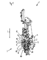
- Blowing station 1 shown is one of a plurality of blowing stations 1 in the FIG. 2 schematically shown forming device 2 for forming plastic preforms (not shown) in plastic containers (also not shown).
- the blowing stations 1 each comprise a blowing device 3, which has a main carrier 4, on which a blow mold 5 is arranged in a blow mold carrier 6 (in each case only partially shown).
- a cavity 7 is formed, within which the plastic preforms are expanded to plastic containers by applying compressed air.
- the blowing device 3 comprises a stretching rod 8, which is movable here in the longitudinal direction L, in order to additionally stretch the plastic preforms during the expansion by the compressed air.
- the blow mold 5 has a first blow mold half 9 and a second blow mold half 10 which are respectively held in corresponding blow mold carrier halves 6A and 6B of the blow mold carrier 6 are.
- the blow mold halves can be arranged on blow mold carrier shells and these in turn on the blow mold carrier halves.
- the blow mold 5 still has a bottom part 11, which closes the cavity 7 downwards in the operational state of the blow mold 5.
- the bottom part 11 is in this operational state of the blow mold 5 as shown in the FIG. 1 in a bottom part operating position 11A, in which also the bottom part 11 limits the cavity 7.
- the bottom part 11 can be lowered in the longitudinal direction L and thereby removed from the blow mold halves 9 and 10.
- the blow mold halves are swung away perpendicular to L.
- the blowing stations can also be of the type in which only one half swung away, the other is fixed.
- the blowing device 3 also comprises a pressurizing device with a blowing head or blowing piston 12 and with a blowing nozzle 13, which pressurizes the plastic preforms with compressed air, so that they can be expanded within the blow mold 5 to the respective plastic containers.
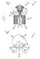
- the in the FIG. 2 Shaping device 2 shown in more detail has a blowing wheel 20, which rotates in the direction of rotation 21.
- a blowing wheel 20 With the blowing wheel 20, a total of eight blowing stations 1 so that the blow molds 5 of the individual blowing devices 3 (see, for example, FIG. FIG. 1 ) in the region of a circulation path 22 by means of an opening and closing mechanism (not shown here) can be opened and closed again.
- the circulation path 22 is in this embodiment in the region of an outlet star 23 for removing the finished blown plastic containers from each passing, open blow molds 5 and an inlet star 24 for inserting the plastic preforms in each case passing, open blow molds 5.
- both the Inlet star 24 and the outlet star 23 corresponding handling elements 25 (only exemplified), by means of which either the plastic preforms (inlet star 24) or the plastic containers (outlet star 23) can be handled.
- the dispensing elements 31 each comprise a spray nozzle 33 (see in particular FIG FIGS. 4 . 7 . 8th . 10 or 11) to the sterilizing agent 32 from outside the stretch rod 8 and the respective blow mold 5 on the lateral surface 35 (see, in particular FIG. 1 ) of the stretch rod 8, so that the outer side 36 of the stretch rod 8 can be sterilized in a sterilization process which is simply integrated into a blowing cycle.
- the spray nozzle 33 can also spray detergent. Cleaning and sterilization are used interchangeably here and beyond.
- the stretch rod 8 is displaced in the region of the circulation path 22 into the cavity 7 of the blow mold 5, as shown in the illustration according to FIG. 3 easy to recognize.
- the stretch rod 8 is displaced with its lower end 37 to above the bottom part functional position 11A addition, so that areas at the upper end 38 of the stretch rod 8 are no longer covered by the pressurizing device and thus achieved and sterilized by the externally sprayed sterilizing agent 32 can be.
- sterilization of the lateral surface 39 of the blowing nozzle 13 could also take place if, alternatively or subsequently, it is at least partially displaced cumulatively into the blow mold 5.
- FIG. 3 you can see how the tuyere 13 has been brought into a position within the blow mold 5, in which it is not encountered in the normal blowing process. Normally, the tuyere sets on the surface of the blow mold 5 or on the preform to be blown for sealing in the blowing process. For sterilization, the tuyere can be driven down even further than is the case in the sealing position.
- the spray nozzle or the sterilizing agent 33 is only out of a valve block 41 of a blow head 12 of the pressurizing device in the direction of the blow mold 5 out to get into the effective range of the spray nozzle 33.
- the stretching rod 8 can thus be moved past the spray nozzle 33, while the spray nozzle 33 sprays the sterilizing agent 32.
- a plurality of spray nozzles 33 arranged one above the other along the longitudinal direction can also be placed radially next to the stretch rod 8.
- the spray nozzle 33 can be displaceable along the longitudinal direction L, so that it can also travel along the stretch rod 8 in order to spray it from top to bottom with sterilizing agent 32.
- the spray nozzle could also be displaceable with a motor drive and / or rotatable about the same or an additional drive.
- an adjustment in three axes is conceivable to spray the stretch rod "from behind", ie from the Blasradmitte radially outward or from the stretch rod holder in the direction of the central axis of the blow mold.
- At least two or more spray nozzles may be positioned around the stretch rod (not shown).
- stretching rod and blowing nozzle can be moved at least once during spraying to each other to clean / sterilize different areas along the longitudinal axis of the stretching rod and / or the blowing nozzle with cleaning and / or sterilizing agent.
- the tuyere and / or stretch rod could be rotatable about its longitudinal axis and rotated by a drive during the sterilization process (not shown). So you could also reach all surfaces in the circumferential direction of the stretch rod or tuyere with only one applicator or nozzle.
- the circulation path 22 relevant here along which the blow molds 5 are open, extends in an angle section 46 between an angle of> 300 ° and an angle of ⁇ 60 °.
- the stretch rod 8 and the tuyere 13 are normally retracted upwardly into the valve block 41.
- at least the stretch rod 8 has moved down from the valve block 41, so that it can be sprayed with sterilizing agent 32, as already explained.
- the sterilization according to the invention can also be carried out in a different circumferential region of the blowing wheel 20 when the shaping device 2 is designed accordingly. This is especially true if, for example, the blow mold carrier 6 or the bottom part 11 are driven by electric motors (not shown here). Also, more guide curves could be provided for this purpose.
- the angle section 46 it is advantageous for the angle section 46 that the blow molds 5 there have to be opened anyway for removal of the plastic containers or assembly of the plastic preforms.
- the blow mold bottom is usually shut down in this area to demold the containers.
- this angular range 46 is advantageous because then the drives anyway already exist at this point. This can thus be used very advantageously for the present sterilization process.
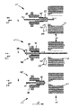
- the blow mold 5 is still closed at an angular position of 300 °.
- the blower wheel 20 continues to rotate in the direction of rotation 21 and the blow mold 5 reaches an angular position of 350 ° (FIG. FIG. 7 ), the blow mold 5 is already open.
- the stretching rod 8 is displaced unscheduled into the blow mold 5 between the two blow mold halves 9 and 10, so that the stretching rod 8 can be sprayed with sterilizing agents 32 from the spray nozzle 33.
- the blowing nozzle 13 is fully retracted into the blowing head 12 of the pressurizing device, so that the blowing nozzle 13 no longer protrudes in front of the valve block 41.
- the stretch rod 8 can be further sterilized during extension and retraction to its upper end 38. Is the blow mold up to an angular position of 10 ° ( FIG. 8 ), the stretch rod 8 moves in again and the tuyere 13, so that in this case now the lateral surface 39 of the tuyere 13 can be sterilized.
- the spray nozzle 33 is displaceably arranged on the sterilization device 30, so that, for example, with respect to the angular positions 350 ° (FIG. FIG. 10) and FIG. 10 ° ( FIG. 11 ) can be arranged centrally above the blow mold 5 so that sterilizing agent 32 can be sprayed from top to bottom in the longitudinal direction L on the blow mold 5 (or radiation lbs..Ladungscht can be directed thereto).
- FIGS. 9-11 show a method for sterilizing the mother mold inner walls during a blow mold change. Here also the outsides of the blow molds can be sterilized.
- the blow mold 5 is still closed at the angular position of 300 °.
- the stretch rod 8 and the tuyere 13 are retracted into the valve block 41.
- the blower wheel 20 continues to rotate in the direction of rotation 21 and the blow mold 5 hereby reaches the angular position of 350 ° (FIG. FIG. 10 ), the blow mold 5 is already open, and between the blowing head 12 and the blow mold 5, the spray nozzle 33 is arranged.
- the stretch rod 8 and the tuyere 13 remain retracted.
- the sterilization means 32 can now be applied from above onto the blow mold 5 and onto the inner mold side 50.
- the blow mold 5 can still be rotated according to the direction of rotation 51 about a horizontal axis in order to be treated both externally and internally with sterilizing agents 32 can. Subsequently, the blow mold 5 (or a new blow mold) at the height of the angular position of 10 ° ( FIG. 11 ) is moved back to the blow mold 6 and is thus ready for another blow process ready.
- a robot or automatic machine is suitable for changing, which accordingly moves the blow molds past sterilization nozzles so that all the surfaces can be sterilized or cleaned (not shown).
- a radiation emitter can also be used as dispensing element 31 for sterilizing agent 32 in order to be able to emit sterilizing agents in the form of charge carriers.
- the sterilizing agent 32 are in this case passed through a first Blas Kunststoffkanal 58 to the outer surface 35 of the stretch rod 8, if this moves out of the alternative valve block 57.
- this is done with the blow mold 5 closed so that the sterilizing agent 32 introduced through the first blown air duct 58 can immediately be led out of the blow mold 5 from a further blown air duct 59.
- these channels can, as stated above, serve to apply blown air to the plastic preforms.
- sterilizing agent is passed from at least one, preferably from both channels 58, 59, in order to sterilize the stretched rod 8 which has been lowered and / or lowered or raised.
- the sterilizing agent used in this case in particular is gaseous H 2 O 2 which, after reaching the stretching rod outer surface, also spreads further to the blow molds and possibly outside the blow mold in the machine. It is only important that the stretch rod is extended at least at one time, while the sterilizing agent flows out of the valve block.
- the tuyere can be fully extended at least one time, so that the outer walls of the tuyere are also sterilized as much as possible.
- the tuyere is movable together with the valve block 57. Here it is actually the surfaces of the valve block that can be sterilized during extension.
- the tuyere is movable relative to the valve block.
- the blow mold can be opened or closed during sterilization, or opened and closed alternately.
- the unmarked black quadrilaterals between stretch rod 8 and block 57 constitute the above-mentioned blast air seal.
- stretch rod 8 which is just above this seal at maximum extension of the stretch rod during stretching, is at Sterilizing or cleaning so far away from the seal, down here from the seal, so that it is also sterilized. In blow stations in which is stretched upward, ie away from the center of the earth, this small part is then up.
- the blast air seal is in the Figures 1-11 not shown, but may be present in all embodiments.
Landscapes
- Engineering & Computer Science (AREA)
- Mechanical Engineering (AREA)
- Manufacturing & Machinery (AREA)
- Blow-Moulding Or Thermoforming Of Plastics Or The Like (AREA)
Applications Claiming Priority (1)
| Application Number | Priority Date | Filing Date | Title |
|---|---|---|---|
| DE201310106694 DE102013106694A1 (de) | 2013-06-26 | 2013-06-26 | Verfahren und Vorrichtung zum Umformen von Kunststoffvorformlingen zu Kunststoffbehältnissen |
Publications (1)
| Publication Number | Publication Date |
|---|---|
| EP2818302A1 true EP2818302A1 (fr) | 2014-12-31 |
Family
ID=51176907
Family Applications (1)
| Application Number | Title | Priority Date | Filing Date |
|---|---|---|---|
| EP20140174602 Withdrawn EP2818302A1 (fr) | 2013-06-26 | 2014-06-26 | Procédé et dispositif de déformation d'ébauches en plastique en conteneurs en plastique |
Country Status (4)
| Country | Link |
|---|---|
| US (1) | US10456954B2 (fr) |
| EP (1) | EP2818302A1 (fr) |
| CN (1) | CN104275792B (fr) |
| DE (1) | DE102013106694A1 (fr) |
Cited By (4)
| Publication number | Priority date | Publication date | Assignee | Title |
|---|---|---|---|---|
| EP2987732B1 (fr) * | 2014-08-20 | 2018-05-02 | Krones AG | Remplisseuse de moule |
| WO2018125721A1 (fr) * | 2016-12-29 | 2018-07-05 | Graham Packaging Company, L.P. | Dispositif de nettoyage de moule de soufflage en ligne et méthode d'utilisation |
| WO2018206752A3 (fr) * | 2017-05-11 | 2019-12-05 | Krones Ag | Procédé destiné à stériliser une machine de moulage par soufflage et machine de moulage par soufflage |
| WO2020070097A3 (fr) * | 2018-10-02 | 2020-06-18 | Khs Corpoplast Gmbh | Procédé et dispositif pour la stérilisation de préformes ou de récipients formés à partir de celles-ci |
Families Citing this family (4)
| Publication number | Priority date | Publication date | Assignee | Title |
|---|---|---|---|---|
| CN108500184A (zh) * | 2013-07-10 | 2018-09-07 | 奥科宁克有限公司 | 用于制作锻造产品和其他加工产品的方法 |
| CN111546606B (zh) * | 2015-03-09 | 2022-05-27 | 大日本印刷株式会社 | 吹塑成型机及其杀菌方法 |
| CN117774275A (zh) * | 2024-02-28 | 2024-03-29 | 山东顺恒塑业有限公司 | 一种塑料桶吹塑成型设备 |
| DE102024106891A1 (de) | 2024-03-11 | 2025-09-11 | Krones Aktiengesellschaft | Vorrichtung und Verfahren zum Umformen von Kunststoffvorformlingen zu Kunststoffbehältnissen mit Reinraum und Partikelentfernungseinrichtung |
Citations (4)
| Publication number | Priority date | Publication date | Assignee | Title |
|---|---|---|---|---|
| WO2012092921A1 (fr) * | 2011-01-04 | 2012-07-12 | Khs Corpoplast Gmbh & Co Kg | Procédé et dispositif de moulage par soufflage de récipients stériles |
| WO2012156013A1 (fr) * | 2011-05-19 | 2012-11-22 | Khs Gmbh | Procédé et dispositif pour nettoyer et/ou désinfecter un dispositif pour la fabrication de contenants remplis d'une matière de remplissage liquide |
| EP2540473A2 (fr) * | 2011-06-27 | 2013-01-02 | Krones AG | Dispositif et procédé de transformation d'ébauches en matière synthétique pour devenir des conteneurs en plastique avec mouvements de tige d'étirage étanches grâce à une membrane enroulable |
| WO2013093634A2 (fr) * | 2011-12-21 | 2013-06-27 | Amcor Limited | Système de moulage avec nettoyage de buse de soufflage |
Family Cites Families (15)
| Publication number | Priority date | Publication date | Assignee | Title |
|---|---|---|---|---|
| FR2774912B1 (fr) * | 1998-02-16 | 2000-09-01 | Sidel Sa | Procede pour steriliser des corps creux et dispositif pour la mise en oeuvre |
| EP2143545A1 (fr) * | 2008-07-07 | 2010-01-13 | Nestec S.A. | Procédé et dispositif de conditionnement d'un liquide alimentaire |
| DE102008032635A1 (de) * | 2008-07-11 | 2010-01-14 | Krones Ag | Blasmaschine und Verfahren zur mikrobioloisch optimierten Herstellung von Kunststoffbehältern |
| DE102009023406A1 (de) * | 2009-05-29 | 2010-12-02 | Krones Ag | Blasmaschine mit CIP-Reinigungssystem zur Herstellung von Kunststoff-Flaschen, insbesondere PET-Flaschen |
| DE102009036922A1 (de) * | 2009-08-11 | 2011-02-17 | Krones Ag | Blasformmaschine mit Reinigungssystem |
| DE102009036920A1 (de) | 2009-08-11 | 2011-02-17 | Krones Ag | Blasformmaschine mit Anordnung zum Reinigen der Blasform |
| ES2390752T3 (es) * | 2009-09-10 | 2012-11-16 | Gea Procomac S.P.A. | Dispositivo de insuflación y estiramiento de una preforma de plástico para obtener un contenedor |
| DE102009040978A1 (de) | 2009-09-11 | 2011-03-17 | Krones Ag | Magazinvorrichtung für Blasformen mit Reinigungseinrichtung |
| DE102010022130A1 (de) * | 2010-05-20 | 2011-11-24 | Krones Ag | Vorrichtung zum Umformen von Kunststoffvorformlingen mit Sterilraum |
| DE102010022128B4 (de) * | 2010-05-20 | 2012-03-15 | Krones Aktiengesellschaft | Vorrichtung zum Umformen von Kunststoffvorformlingen mit Sterilraum |
| DE102010022131A1 (de) * | 2010-05-20 | 2011-11-24 | Krones Ag | Sterilisierbare Blasform |
| DE102010021446A1 (de) * | 2010-05-25 | 2011-12-01 | Krones Ag | Verfahren und Vorrichtung zur Temperierung von Vorformlingen |
| DE202010017218U1 (de) * | 2010-06-01 | 2010-06-09 | Krones Ag, 93073 | Vorrichtung zum Überprüfen der Reinigungswirkung einer Reinigungsvorrichtung |
| DE102011105744A1 (de) * | 2011-06-24 | 2013-01-10 | Krones Aktiengesellschaft | Vorrichtung und Verfahren zum Umformen von Kunststoffvorformlingen zu Kunststoffbehältnissen mit abgedichteter Reckstangenbewegung |
| DE102013013591A1 (de) * | 2013-08-19 | 2015-02-19 | Khs Corpoplast Gmbh | Verfahren und Vorrichtung zur blasformenden Herstellung von zumindest bereichsweise sterilen Behältern |
-
2013
- 2013-06-26 DE DE201310106694 patent/DE102013106694A1/de not_active Withdrawn
-
2014
- 2014-06-25 US US14/314,529 patent/US10456954B2/en not_active Expired - Fee Related
- 2014-06-26 EP EP20140174602 patent/EP2818302A1/fr not_active Withdrawn
- 2014-06-26 CN CN201410294738.3A patent/CN104275792B/zh not_active Expired - Fee Related
Patent Citations (4)
| Publication number | Priority date | Publication date | Assignee | Title |
|---|---|---|---|---|
| WO2012092921A1 (fr) * | 2011-01-04 | 2012-07-12 | Khs Corpoplast Gmbh & Co Kg | Procédé et dispositif de moulage par soufflage de récipients stériles |
| WO2012156013A1 (fr) * | 2011-05-19 | 2012-11-22 | Khs Gmbh | Procédé et dispositif pour nettoyer et/ou désinfecter un dispositif pour la fabrication de contenants remplis d'une matière de remplissage liquide |
| EP2540473A2 (fr) * | 2011-06-27 | 2013-01-02 | Krones AG | Dispositif et procédé de transformation d'ébauches en matière synthétique pour devenir des conteneurs en plastique avec mouvements de tige d'étirage étanches grâce à une membrane enroulable |
| WO2013093634A2 (fr) * | 2011-12-21 | 2013-06-27 | Amcor Limited | Système de moulage avec nettoyage de buse de soufflage |
Cited By (5)
| Publication number | Priority date | Publication date | Assignee | Title |
|---|---|---|---|---|
| EP2987732B1 (fr) * | 2014-08-20 | 2018-05-02 | Krones AG | Remplisseuse de moule |
| WO2018125721A1 (fr) * | 2016-12-29 | 2018-07-05 | Graham Packaging Company, L.P. | Dispositif de nettoyage de moule de soufflage en ligne et méthode d'utilisation |
| WO2018206752A3 (fr) * | 2017-05-11 | 2019-12-05 | Krones Ag | Procédé destiné à stériliser une machine de moulage par soufflage et machine de moulage par soufflage |
| WO2020070097A3 (fr) * | 2018-10-02 | 2020-06-18 | Khs Corpoplast Gmbh | Procédé et dispositif pour la stérilisation de préformes ou de récipients formés à partir de celles-ci |
| CN112805039A (zh) * | 2018-10-02 | 2021-05-14 | Khs科波普拉斯特有限责任公司 | 用于消毒预制型坯或由此成型的容器的方法及设备 |
Also Published As
| Publication number | Publication date |
|---|---|
| DE102013106694A1 (de) | 2015-01-15 |
| CN104275792B (zh) | 2018-07-17 |
| US20150001747A1 (en) | 2015-01-01 |
| CN104275792A (zh) | 2015-01-14 |
| US10456954B2 (en) | 2019-10-29 |
Similar Documents
| Publication | Publication Date | Title |
|---|---|---|
| EP2818302A1 (fr) | Procédé et dispositif de déformation d'ébauches en plastique en conteneurs en plastique | |
| EP2283991B1 (fr) | Machine de formage par soufflage dotée d'un système de nettoyage | |
| DE102008038141B4 (de) | Vorrichtung mit Reinraum zum Umformen von Kunststoffvorformlingen zu Kunststoffbehältnissen und Anlage zum Herstellen von Kunststoffbehältnissen sowie Verfahren zum Umformen von Kunststoffvorformlingen zu Kunststoffbehältnissen | |
| EP2275214B1 (fr) | Dispositif de traitement de récipients par stérilisation de support | |
| EP2556943B1 (fr) | Souffleuse, procédé d'échange de composants de stations de soufflage ainsi qu'installation de remplissage de boissons et/ou installation de fabrication de récipients de boissons | |
| EP2709819B1 (fr) | Procédé et dispositif pour nettoyer et/ou désinfecter un dispositif pour la fabrication de contenants remplis d'une matière de remplissage liquide | |
| EP2431058B1 (fr) | Unité de stérilisation aseptisée pour une salle blanche | |
| EP3815877A1 (fr) | Changement automatique de garniture dans une installation de remplissage de boissons | |
| DE102010022130A1 (de) | Vorrichtung zum Umformen von Kunststoffvorformlingen mit Sterilraum | |
| DE102011122853B4 (de) | Blasmaschine, Verfahren zum Austauschen von Blasstationskomponenten sowie Getränkeabfüllanlage und/oder Getränkebehälterherstellanlage | |
| DE102011102056B4 (de) | Verfahren sowie Vorrichtung zum Herstellen von gefüllten Behältern aus Vorformlingen | |
| DE102012106310A1 (de) | Vorrichtung zum Erwärmen von Kunststoffvorformlingen mit Sterilraum | |
| DE102011013126A1 (de) | Blasmaschine mit Blasformverriegelung im Reinraum | |
| EP2420258B1 (fr) | Dispositif de traitement d'emballages | |
| DE202013008055U1 (de) | Vorrichtung zum Umformen von Kunststoffvorformlingen mit Reinraum | |
| EP2522485B1 (fr) | Machine et procédé de formage par soufflage aseptique avec évacuation stérile de l'air, ainsi que moule de soufflage | |
| DE102011105744A1 (de) | Vorrichtung und Verfahren zum Umformen von Kunststoffvorformlingen zu Kunststoffbehältnissen mit abgedichteter Reckstangenbewegung | |
| EP3036082A1 (fr) | Procédé et dispositif permettant de produire des contenants stériles au moins par endroits | |
| EP2832523B1 (fr) | Machine de formage par soufflage stérile et procédé | |
| EP4296034B1 (fr) | Installation et procédé de fonctionnement d'une installation de fabrication de récipients en plastique remplis à partir de préformes en plastique stériles | |
| EP2987618B1 (fr) | Remplisseuse de moule et procédé de moulage et de remplissage de récipients | |
| EP2684674A1 (fr) | Dispositif de chauffage stérile pour ébauches en plastique et le procédé | |
| EP1814603A1 (fr) | Procede et dispositif de sterilisation de bouteilles en plastique en mouvement continu | |
| DE102010064425B4 (de) | Vorrichtung zum Umformen von Kunststoffvorformlingen mit Sterilraum und Anlage zum Herstellen von Kunststoffbehältnissen | |
| DE202008018392U1 (de) | Vorrichtung zum Umformen von Kunststoffvorformlingen mit Sterilraum |
Legal Events
| Date | Code | Title | Description |
|---|---|---|---|
| PUAI | Public reference made under article 153(3) epc to a published international application that has entered the european phase |
Free format text: ORIGINAL CODE: 0009012 |
|
| 17P | Request for examination filed |
Effective date: 20140626 |
|
| AK | Designated contracting states |
Kind code of ref document: A1 Designated state(s): AL AT BE BG CH CY CZ DE DK EE ES FI FR GB GR HR HU IE IS IT LI LT LU LV MC MK MT NL NO PL PT RO RS SE SI SK SM TR |
|
| AX | Request for extension of the european patent |
Extension state: BA ME |
|
| R17P | Request for examination filed (corrected) |
Effective date: 20150630 |
|
| RBV | Designated contracting states (corrected) |
Designated state(s): AL AT BE BG CH CY CZ DE DK EE ES FI FR GB GR HR HU IE IS IT LI LT LU LV MC MK MT NL NO PL PT RO RS SE SI SK SM TR |
|
| 17Q | First examination report despatched |
Effective date: 20170713 |
|
| STAA | Information on the status of an ep patent application or granted ep patent |
Free format text: STATUS: THE APPLICATION IS DEEMED TO BE WITHDRAWN |
|
| 18D | Application deemed to be withdrawn |
Effective date: 20191203 |