EP2818622A1 - Sektionaltor, insbesondere für Ladungsträger im Frachtverkehr - Google Patents
Sektionaltor, insbesondere für Ladungsträger im Frachtverkehr Download PDFInfo
- Publication number
- EP2818622A1 EP2818622A1 EP14168609.7A EP14168609A EP2818622A1 EP 2818622 A1 EP2818622 A1 EP 2818622A1 EP 14168609 A EP14168609 A EP 14168609A EP 2818622 A1 EP2818622 A1 EP 2818622A1
- Authority
- EP
- European Patent Office
- Prior art keywords
- panels
- narrow side
- sectional door
- panel
- anschraubbänder
- Prior art date
- Legal status (The legal status is an assumption and is not a legal conclusion. Google has not performed a legal analysis and makes no representation as to the accuracy of the status listed.)
- Granted
Links
Images


Classifications
-
- E—FIXED CONSTRUCTIONS
- E06—DOORS, WINDOWS, SHUTTERS, OR ROLLER BLINDS IN GENERAL; LADDERS
- E06B—FIXED OR MOVABLE CLOSURES FOR OPENINGS IN BUILDINGS, VEHICLES, FENCES OR LIKE ENCLOSURES IN GENERAL, e.g. DOORS, WINDOWS, BLINDS, GATES
- E06B3/00—Window sashes, door leaves, or like elements for closing wall or like openings; Layout of fixed or moving closures, e.g. windows in wall or like openings; Features of rigidly-mounted outer frames relating to the mounting of wing frames
- E06B3/32—Arrangements of wings characterised by the manner of movement; Arrangements of movable wings in openings; Features of wings or frames relating solely to the manner of movement of the wing
- E06B3/48—Wings connected at their edges, e.g. foldable wings
- E06B3/485—Sectional doors
-
- B—PERFORMING OPERATIONS; TRANSPORTING
- B60—VEHICLES IN GENERAL
- B60J—WINDOWS, WINDSCREENS, NON-FIXED ROOFS, DOORS, OR SIMILAR DEVICES FOR VEHICLES; REMOVABLE EXTERNAL PROTECTIVE COVERINGS SPECIALLY ADAPTED FOR VEHICLES
- B60J5/00—Doors
- B60J5/10—Doors arranged at the vehicle rear
- B60J5/12—Doors arranged at the vehicle rear slidable; foldable
- B60J5/14—Doors arranged at the vehicle rear slidable; foldable of roller-blind type made of rigid elements
-
- E—FIXED CONSTRUCTIONS
- E05—LOCKS; KEYS; WINDOW OR DOOR FITTINGS; SAFES
- E05D—HINGES OR SUSPENSION DEVICES FOR DOORS, WINDOWS OR WINGS
- E05D15/00—Suspension arrangements for wings
- E05D15/16—Suspension arrangements for wings for wings sliding vertically more or less in their own plane
- E05D15/24—Suspension arrangements for wings for wings sliding vertically more or less in their own plane consisting of parts connected at their edges
- E05D15/242—Hinge connections between the parts
-
- E—FIXED CONSTRUCTIONS
- E05—LOCKS; KEYS; WINDOW OR DOOR FITTINGS; SAFES
- E05D—HINGES OR SUSPENSION DEVICES FOR DOORS, WINDOWS OR WINGS
- E05D15/00—Suspension arrangements for wings
- E05D15/16—Suspension arrangements for wings for wings sliding vertically more or less in their own plane
- E05D15/24—Suspension arrangements for wings for wings sliding vertically more or less in their own plane consisting of parts connected at their edges
- E05D15/244—Upper part guiding means
-
- E—FIXED CONSTRUCTIONS
- E06—DOORS, WINDOWS, SHUTTERS, OR ROLLER BLINDS IN GENERAL; LADDERS
- E06B—FIXED OR MOVABLE CLOSURES FOR OPENINGS IN BUILDINGS, VEHICLES, FENCES OR LIKE ENCLOSURES IN GENERAL, e.g. DOORS, WINDOWS, BLINDS, GATES
- E06B3/00—Window sashes, door leaves, or like elements for closing wall or like openings; Layout of fixed or moving closures, e.g. windows in wall or like openings; Features of rigidly-mounted outer frames relating to the mounting of wing frames
- E06B3/32—Arrangements of wings characterised by the manner of movement; Arrangements of movable wings in openings; Features of wings or frames relating solely to the manner of movement of the wing
- E06B3/48—Wings connected at their edges, e.g. foldable wings
- E06B3/485—Sectional doors
- E06B3/486—Sectional doors with hinges being at least partially integral part of the section panels
-
- E—FIXED CONSTRUCTIONS
- E05—LOCKS; KEYS; WINDOW OR DOOR FITTINGS; SAFES
- E05Y—INDEXING SCHEME ASSOCIATED WITH SUBCLASSES E05D AND E05F, RELATING TO CONSTRUCTION ELEMENTS, ELECTRIC CONTROL, POWER SUPPLY, POWER SIGNAL OR TRANSMISSION, USER INTERFACES, MOUNTING OR COUPLING, DETAILS, ACCESSORIES, AUXILIARY OPERATIONS NOT OTHERWISE PROVIDED FOR, APPLICATION THEREOF
- E05Y2800/00—Details, accessories and auxiliary operations not otherwise provided for
- E05Y2800/10—Additional functions
- E05Y2800/12—Sealing
-
- E—FIXED CONSTRUCTIONS
- E05—LOCKS; KEYS; WINDOW OR DOOR FITTINGS; SAFES
- E05Y—INDEXING SCHEME ASSOCIATED WITH SUBCLASSES E05D AND E05F, RELATING TO CONSTRUCTION ELEMENTS, ELECTRIC CONTROL, POWER SUPPLY, POWER SIGNAL OR TRANSMISSION, USER INTERFACES, MOUNTING OR COUPLING, DETAILS, ACCESSORIES, AUXILIARY OPERATIONS NOT OTHERWISE PROVIDED FOR, APPLICATION THEREOF
- E05Y2900/00—Application of doors, windows, wings or fittings thereof
- E05Y2900/10—Application of doors, windows, wings or fittings thereof for buildings or parts thereof
- E05Y2900/106—Application of doors, windows, wings or fittings thereof for buildings or parts thereof for garages
-
- E—FIXED CONSTRUCTIONS
- E05—LOCKS; KEYS; WINDOW OR DOOR FITTINGS; SAFES
- E05Y—INDEXING SCHEME ASSOCIATED WITH SUBCLASSES E05D AND E05F, RELATING TO CONSTRUCTION ELEMENTS, ELECTRIC CONTROL, POWER SUPPLY, POWER SIGNAL OR TRANSMISSION, USER INTERFACES, MOUNTING OR COUPLING, DETAILS, ACCESSORIES, AUXILIARY OPERATIONS NOT OTHERWISE PROVIDED FOR, APPLICATION THEREOF
- E05Y2900/00—Application of doors, windows, wings or fittings thereof
- E05Y2900/50—Application of doors, windows, wings or fittings thereof for vehicles
- E05Y2900/516—Application of doors, windows, wings or fittings thereof for vehicles for trucks or trailers
Definitions
- the invention relates to a sectional door, in particular for load carriers in freight traffic.
- the load carrier may be, for example, the loading space of a pickup truck or truck.
- the term "load carriers” also includes in particular semitrailers and swap bodies, where semitrailers are semitrailers which are separated from the cab of a motor vehicle and coupled via a fifth wheel, and swap bodies denote container-like interchangeable load carriers which can be separated from the carrier vehicle.
- the sectional door comprises a door leaf of articulated panels, which are pivotally connected by bolting and guided in lateral rails.
- the panels of the door leaf have on their upper narrow side a convex profile section, which is followed by a step-shaped shoulder on the inside of the door leaf. At its lower narrow side, the panels have a rib which engages in the Torblattschwhoschreib in the stepped shoulder on the upper narrow side of the adjacent panel.
- the Anschraubb comprise a pivot arm which is pivotally mounted between two side walls of a console and connected by an axis with the console.
- a sectional door leaf having the features described above is made DE 20 2004 013 807 U1 known.
- the sectional door leaf is especially designed for garage and industrial doors.
- the panels are assembled from sheet metal shells and filled with foam.
- the foamed sheet metal panels are heavy and, due to their weight and dimensions, unsuitable for cargo applications.
- the Blechschalenkonstrutation and the foaming of the sheet metal shells also requires deviations that the Limiting the possible use of the sectional door outside the garage and industrial door area.
- the DE 29 18 638 A1 refers to a sectional door for applications in freight transport, for example as a closure for truck trailers.
- the panels consist of plates which have a groove-shaped depression on their lower narrow side and a trapezoidal profile on their upper narrow side.
- the panels are hinged together by bolting.
- the Anschraubbs are designed as roller belts and have an axis, which are also used as an axis for the guided in the lateral rails rollers.
- the door leaf is still in need of improvement. Furthermore, there is the problem that during opening and closing movements, a gap between the pivotally connected panels opens and closes again, so that a finger clamping risk results in a manual operation of the door.
- the present invention seeks to provide a sectional door for cargo carriers in freight traffic, the door leaf is dimensionally stable and transverse forces that may occur, for example, by an insufficiently secured charge record.
- a finger trap risk should be excluded.
- both a faster and easier roller replacement as well as an exchange of individual panels should be possible.
- the door leaf having the features described above, the object is achieved in that the panels consist of extruded hollow sections, which have several limited by transverse webs chambers, wherein the rib on the lower narrow side of the panels as a single-walled projection of the hollow profile is formed and wherein the corresponding step-shaped shoulder is formed on the upper narrow side of the panels in the hollow profile.
- the panels which are manufactured in one piece as extruded hollow sections, are characterized by low weight, high dimensional stability, precise contours and high dimensional accuracy.
- the panels connected by screw-on hinges can be adjusted exactly by adjusting the bands so that only a minimal gap is created between the panels in the closed state.
- the rib on the lower narrow side of the panels is preferably supported in the Torblattsch spaschreib on the stepped shoulder which is integrally formed on the upper narrow side of the adjacent panel.
- the support of the panels with narrow sides facing each other contributes to the fact that the door leaf is dimensionally stable in the closed state.
- the hollow profiles made of aluminum, light metal alloys or plastic.
- the console of the Anschraubb is suitably arranged in a recess of the hollow profiles so that the axis of the Anschraubb an is substantially aligned with the torblattinnen solution of the panel. It is achievable, inter alia, by this arrangement, that during a pivoting movement of the panels about the axis of the fastening strips over a large pivot angle range, an overlap of the facing surfaces on the lower and upper narrow sides of the panels is ensured. Furthermore, the projection of the Anschraubb selected can be reduced to the Torblattinnen Diagram, so that the loading space of the closed by the sectional door load carrier can be used up to the door leaf for cargo.
- the console is fitted in the recess of the hollow profiles and supported at its lower end to a shoulder of the recess. Over the shoulder, axial forces can be introduced into the door leaf and screw connections, with which the console of the Anschraubb S are attached to the panels, be relieved.
- axial forces can be introduced into the door leaf and screw connections, with which the console of the Anschraubb S are attached to the panels, be relieved.
- the trained as engagement protection side cheeks of Anschraubb have a terminal edge, which preferably connects to the stepped shoulder of the hollow sections and has a convexly curved profile.
- the profile of the terminal edges is adapted to the trajectory that describes the rib in a pivotal movement of the panel about the axis of the Anschraubb selected.
- the hollow profiles have expediently for stiffening the contact surface for the consoles on a cross bar, which extends from the door leaf outer side panel surface to the door leaf inside panel surface and is formed at the level of the hinge axis of the Anschraubb selected to the contact surface.
- the panels have on their upper narrow side a seal which bridges a gap between a lower edge on the Torblattau type of the adjacent panel and a shoulder surface of the hollow profile in the closed state of the door leaf.
- the hollow profiles on its upper narrow side between the shoulder surface and the convex profile section a groove.
- the seal expediently consists of a plastic profile which has a bead which can be inserted into the groove and a freely projecting lip. The lip is dimensioned so that it rests in the Torblattschsted ein on the shoulder surface of the hollow profile and is clamped between the shoulder surface and the lower edge of the Torblattau combinites of the adjacent panel.
- the hollow profiles of the panels have on their lower narrow side on a concave profile section which extends from a lower edge of the hollow profiles on the Torblattau type to an arranged immediately in front of the rib groove for fixing a seal.
- This seal is expediently designed as a lip seal, which slides on a pivotal movement of the panels on the convex profile section of the adjacent panel and the convexly curved profile along the side cheeks Aufschraubb.
- the seals described may be provided individually or combined with each other.
- Adjacent panels of the sectional door leaf are preferably pivotably connected by at least two Anschraubb sources.
- a further advantageous embodiment provides that the axes of the two Anschraubb selected protrude on the longitudinal sides of the door leaf and that are mounted on the axles rollers or roller assemblies for guidance in the rails.
- the panels of the Se Erasmusaltorblattes are guided with roller assemblies in the rails, each having a rotatably mounted on the hinge axis of the Anschraubb selected carrier and at least one rotatably mounted on the carrier roller.
- two rollers are rotatably mounted on the carrier of the roller assemblies whose Distance from each other is adjustable.
- the roller assemblies form so-called tandem rollers and allow a particularly smooth guiding of the panels.
- the rollers are expediently made of stainless steel, are ball bearings, encapsulated and adjustable.
- the top panel of the door leaf in the closed position is also referred to below as the head panel.
- To the head panel runners may be connected, which are guided in the guide rails and having a pivotally connected to the head panel arm.
- the arm bridges a gap between the door leaf plane and an arcuately curved portion of the side rails.
- the carriage holds the head panel of the door leaf in a vertical end position.
- the head panel unlike the bottom side panels, have on its upper narrow side a flat end surface.
- the lowest in the closed position panel has on its lower narrow side positive engagement training for attachment of a bottom seal.
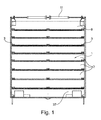
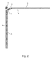
- the sectional door shown in the figures is intended for load carriers in freight traffic, for example for cargo holds of transport vehicles, semitrailer or swap bodies.
- the sectional door comprises a door leaf 1 of hinged panels 2, which are pivotally connected by bolting 3 and guided in lateral rails 4.
- the rails 4 have a vertical portion 5, a horizontal portion 6 and an arcuate connecting portion 7.
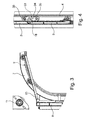
- the uppermost in the Torblattsch donated ein panel, which is also referred to as head panel 8 is connected to carriage 9, which are guided in the rails 4 and having a pivotally connected to the head panel 8 arm 10.
- the arm 10 holds the head panel 8 in the door leaf closed position in a vertical orientation.
- the door leaf 1 is connected to a weight compensation device 11 which is formed in the embodiment as a torsion spring shaft.
- the weight compensation device can also have tension springs in a manner known per se. It is connected by pull ropes to the lower end of the door leaf 1.
- the traction cables are arranged in Zargenprofilen the Torzarge and not visible from the outside.
- FIG. 5a and 5b the facing portions of two hinged panels 2 of the sectional door are shown.
- the Fig. 5a shows the closed position in which the panels 2 are vertically aligned and form a vertical Torblatt Definition.
- the panels 2 are guided along the side rail 4 and pass through the arcuate connecting portion 7 of the rails 4.
- the panels 2 perform relative pivoting movements to each other, as in Fig. 5b is shown.
- the Fig. 5b shows the maximum swivel angle ⁇ . Between the surfaces of the mutually facing narrow sides of the panels 2 remains an overlap. This overlap prevents fingers from being squeezed when opening and closing the door manually.
- the panels 2 on its upper narrow side a convex profile section 12, to which a door-shaped inner side of a stepped shoulder 13 connects.
- the panels 2 At its lower narrow side, the panels 2 have a rib 14 which engages in the Torblattschwhoschreib in the stepped shoulder 13 on the upper narrow side of the adjacent panel.
- the Anschraubb section 3 which connect the panels 2 articulated, have a pivot arm 15 which is pivotally mounted between two side walls 16 of a bracket 17 and connected by an axis 18 with the bracket 17.
- the axis 18 is hereinafter also referred to as a hinge axis.
- the side cheeks 16 form a lateral engagement protection on the inside of the door leaf 1 and prevent there also a finger trapping.
- the panels 2 consist of extruded hollow sections 21 which have a plurality of chambers 20 limited by transverse webs 19.
- a formed as a recess abutment surface 38 for the brackets 17 of the Anschraubb S is stiffened by a transverse web 19 which extends from the torblattau dry solution surface to the torblattinnen solutionen panel surface and is formed at the level of the hinge axis 18 to the contact surface 38.
- the bracket 17 of the Anschraubb testing 3 is arranged in the described recess of the hollow sections 21 so that the axis 18 of the Anschraubb S 3 is substantially aligned with the torblattinnen sketchen surface of the panel 2. Further, the bracket 17 is fitted in the recess and supported at its lower end to a shoulder 22 of the recess. As a result, the position of the Anschraubb selected 3 is exactly defined.
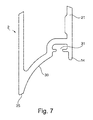
- the trained as engagement protection side cheeks 16 of the Anschraubb basic 3 also have a terminal edge 23, which connects to the stepped shoulder 13 of the hollow sections 21 and has a convexly curved profile. The profile of the terminal edges 23 is adapted to the trajectory which describes the rib 14 during a pivoting movement of the panel 2b.
- the panels 2 have on their upper narrow side a seal 24 which, in the closed state of the door leaf 1, bridges a gap between a lower edge 25 on the door leaf side of the adjacent panel and a shoulder surface 26 of the hollow profile 21.
- a groove 27 is provided, which is arranged on the upper narrow side of the hollow profiles 21 between the shoulder surface 26 and the convex profile section 12.
- the seal 24 has an insertable into the groove bead 28 and a freely projecting lip 29. In the Torblattscheuerles the lip 29 is located on the Shoulder surface 26 and is clamped between the shoulder surface 26 and the lower edge 25 of the hinged panel ( Fig. 5a ).
- the hollow profiles 21 have on their lower narrow side a concave profile section 30 which extends from a lower edge 25 of the hollow sections 21 on the Torblattau builtseite to a disposed immediately in front of the rib 14 groove 31 for fastening a seal 32.
- a lip seal 32 is arranged, which slides at a pivotal movement of the panels 2 on the convex profile section 12 of the adjacent panel and the convexly curved end edges 23 on the side cheeks 16 of 3 Anschraubb.
- the rib 14 is supported on the stepped shoulder 13 of the upper narrow side of the adjacent panel.
- the panels 2 are each pivotally connected by at least two Anschraubbs 3, wherein the Anschraubbs 3 are mounted on the sides of the door leaf.
- the hinge axes 18 of the laterally arranged Anschraubb primary 3 project on the longitudinal sides of the door leaf 1 and are used for storage of moving in the rails 4 rollers or roller assemblies 33.
- the roller assemblies 33 each have a support 34 rotatably mounted on the axle 18.
- two rollers 35 are rotatably mounted, whose distance from one another is adjustable.
- the rollers 35 are equipped with rolling bearings and allow a low-friction running.
- the head panel 8 may have a flat end surface on its upper narrow side.
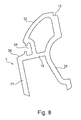
- the lowest in the closed position panel 37 has on its lower narrow side expedient positive engagement formations 36 for attachment of a bottom seal on ( Fig. 10 ).
Landscapes
- Engineering & Computer Science (AREA)
- Mechanical Engineering (AREA)
- Civil Engineering (AREA)
- Structural Engineering (AREA)
- Wing Frames And Configurations (AREA)
Abstract
Description
- Die Erfindung betrifft ein Sektionaltor, insbesondere für Ladungsträger im Frachtverkehr. Bei dem Ladungsträger kann es sich beispielsweise um den Laderaum eines Kleintransporters oder LKWs handeln. Unter den Begriff "Ladungsträger" fallen insbesondere auch Sattelkoffer und Wechselbrücken, wobei Sattelkoffer Sattelauflieger sind, die der vom Führerhaus eines Motorfahrzeuges getrennt und über eine Sattelkupplung angekuppelt werden, und wobei Wechselbrücken containerartige austauschbare Ladungsträger bezeichnen, die sich vom Trägerfahrzeug trennen lassen.
- Das Sektionaltor umfasst ein Torblatt aus gelenkig verbundenen Paneelen, die durch Anschraubbänder schwenkbeweglich verbunden und in seitlichen Laufschienen geführt sind. Die Paneele des Torblattes weisen an ihrer oberen Schmalseite einen konvexen Profilabschnitt auf, an den an der Torblatt-innenseite ein stufenförmiger Absatz anschließt. An ihrer unteren Schmalseite weisen die Paneele eine Rippe auf, die im Torblattschließzustand in den stufenförmigen Absatz an der oberen Schmalseite des benachbarten Paneels eingreift. Die Anschraubbänder umfassen einen Schwenkarm, der zwischen zwei Seitenwangen einer Konsole schwenkbar angeordnet und durch eine Achse mit der Konsole verbunden ist.
- Ein Sektionaltorblatt mit den vorstehend beschriebenen Merkmalen ist aus
DE 20 2004 013 807 U1 bekannt. Das Sektionaltorblatt ist insbesondere für Garagen- und Industrietore bestimmt. Die Paneele werden aus Blechschalen zusammengesetzt und ausgeschäumt. Die ausgeschäumten Blechpaneele sind schwer und aufgrund ihres Gewichtes und ihrer Abmessungen für Anwendungen im Frachtverkehr nicht geeignet. Die Blechschalenkonstruktion und das Ausschäumen der Blechschalen bedingt ferner Maßabweichungen, die die Einsatzmöglichkeit des Sektionaltores außerhalb des Garagen- und Industrietorbereiches einschränken. - Die
DE 29 18 638 A1 bezieht sich auf ein Sektionaltor für Anwendungen im Frachtverkehr, beispielsweise als Verschluss für LKW-Anhänger. Die Paneele bestehen aus Platten, die an ihrer unteren Schmalseite eine nutförmige Vertiefung und an ihrer oberen Schmalseite ein trapezförmiges Profil aufweisen. Im Torblattschließzustand greifen die gelenkig miteinander verbundenen Paneele an ihren Schmalseiten nach Art einer Nut- und Federverbindung ineinander. Die Paneele sind durch Anschraubbänder gelenkig miteinander verbunden. Die Anschraubbänder sind als Rollenbänder ausgebildet und weisen eine Achse auf, die zugleich als Achse für die in den seitlichen Laufschienen geführten Laufrollen genutzt werden. Hinsichtlich ihres Flächengewichtes und der Formstabilität ist das Torblatt noch verbesserungsbedürftig. Ferner ergibt sich das Problem, dass sich bei Öffnungs- und Schließbewegungen ein Spalt zwischen den schwenkbeweglich verbundenen Paneelen öffnet und wieder schließt, so dass bei einer manuellen Betätigung des Tores eine Fingerklemmgefahr resultiert. - Vor diesem Hintergrund liegt der Erfindung die Aufgabe zugrunde, ein Sektionaltor für Ladungsträger im Frachtverkehr anzugeben, dessen Torblatt formstabil ist und Querkräfte, die beispielsweise durch eine unzureichend gesicherte Ladung auftreten können, aufnehmen kann. Beim Öffnen und Schließen des Torblattes soll eine Fingerklemmgefahr ausgeschlossen sein. Ferner sollen sowohl ein schneller und einfacher Laufrollenaustausch als auch ein Austausch einzelner Paneele möglich sein.
- Gegenstand der Erfindung und Lösung dieser Aufgabe ist ein Sektionaltor nach Anspruch 1.
- Ausgehend von einem Sektionaltor, dessen Torblatt die eingangs beschriebenen Merkmale aufweist, wird die Aufgabe erfindungsgemäß dadurch gelöst, dass die Paneele aus stranggeformten Hohlprofilen bestehen, die mehrere durch Querstege begrenzte Kammern aufweisen, wobei die Rippe an der unteren Schmalseite der Paneele als einwandiger Vorsprung des Hohlprofils ausgebildet ist und wobei der korrespondierende stufenförmige Absatz an der oberen Schmalseite der Paneele in das Hohlprofil eingeformt ist. Die einteilig als stranggeformte Hohlprofile gefertigten Paneele zeichnen sich durch ein geringes Gewicht, hohe Formstabilität, exakte Konturen und große Maßgenauigkeit aus. Die durch Anschraubbänder verbundenen Paneele können durch Einstellungen an den Bändern exakt so eingestellt werden, dass sich zwischen den Paneelen im Schließzustand nur ein minimaler Spalt einstellt. Die Rippe an der unteren Schmalseite der Paneele ist im Torblattschließzustand vorzugsweise auf dem stufenförmigen Absatz, der an der oberen Schmalseite des benachbarten Paneels angeformt ist, abgestützt. Durch die Abstützung können die Anschraubbänder entlastet werden. Gleichzeitig trägt die Abstützung der Paneele mit einander zugewandten Schmalseiten dazu bei, dass das Torblatt im Schließzustand formstabil ist. Vorzugsweise bestehen die Hohlprofile aus Aluminium, Leichtmetalllegierungen oder Kunststoff.
- Die Konsole der Anschraubbänder ist zweckmäßig in einer Vertiefung der Hohlprofile so angeordnet, dass die Achse der Anschraubbänder im Wesentlichen mit der torblattinnenseitigen Fläche des Paneels fluchtet. Durch diese Anordnung ist unter anderem erreichbar, dass bei einer Schwenkbewegung der Paneele um die Achse der Anschraubbänder über einen großen Schwenkwinkelbereich eine Überdeckung der einander zugewandten Flächen an der unteren und oberen Schmalseite der Paneele gewährleistet ist. Ferner kann der Überstand der Anschraubbänder an der Torblattinnenfläche reduziert werden, so dass der Laderaum des von dem Sektionaltor verschlossenen Ladungsträgers bis zum Torblatt für Frachtgut genutzt werden kann. Vorzugsweise ist die Konsole in die Vertiefung der Hohlprofile eingepasst und an ihrem unteren Ende an einer Schulter der Vertiefung abgestützt. Über die Schulter können axiale Kräfte in das Torblatt eingeleitet und Schraubverbindungen, mit denen die Konsole der Anschraubbänder an den Paneelen befestigt sind, entlastet werden. Durch die Einpassung der Konsolen in zugeordnete Vertiefungen der stranggeformten Hohlprofile ist ferner eine exakte Position der Anschraubbänder sichergestellt. Die exakte Positionierung der Anschraubbänder an den Paneelen trägt maßgeblich dazu bei, dass zwischen den Paneelen ein geringes Spaltmaß realisiert werden kann.
- Die als Eingriffschutz ausgebildeten Seitenwangen der Anschraubbänder weisen eine Abschlusskante auf, die vorzugsweise an den stufenförmigen Absatz der Hohlprofile anschließt und ein konvex gekrümmtes Profil aufweist. Das Profil der Abschlusskanten ist an die Bahnkurve angepasst, welche die Rippe bei einer Schwenkbewegung des Paneels um die Achse der Anschraubbänder beschreibt.
- Die Hohlprofile weisen zweckmäßig zur Aussteifung der Anlagefläche für die Konsolen einen Quersteg auf, der sich von der torblattaußenseitigen Paneelfläche bis zur torblattinnenseitigen Paneelfläche erstreckt und in Höhe der Scharnierachse der Anschraubbänder an die Anlagefläche angeformt ist.
- Zur Abdichtung des Spaltes, der im Torblattschließzustand zwischen den Paneelen verbleibt, sind zweckmäßig Dichtungen vorgesehen. Gemäß einer bevorzugten Ausführung der Erfindung weisen die Paneele an ihrer oberen Schmalseite eine Dichtung auf, die im Schließzustand des Torblattes einen Spalt zwischen einem unteren Rand an der Torblattaußenseite des benachbarten Paneels und einer Schulterfläche des Hohlprofils überbrückt. Zur Befestigung der Dichtung weisen die Hohlprofile an ihrer oberen Schmalseite zwischen der Schulterfläche und dem konvexen Profilabschnitt eine Nut auf. Die Dichtung besteht zweckmäßig aus einem Kunststoffprofil, welches eine in die Nut einsetzbare Wulst sowie eine frei vorstehende Lippe aufweist. Die Lippe ist so bemessen, dass sie in der Torblattschließstellung auf der Schulterfläche des Hohlprofils aufliegt und zwischen der Schulterfläche und dem unteren Rand an der Torblattaußenseite des benachbarten Paneels eingeklemmt ist.
- Die Hohlprofile der Paneele weisen an ihrer unteren Schmalseite einen konkaven Profilabschnitt auf, der sich von einem unteren Rand der Hohlprofile an der Torblattaußenseite bis zu einer unmittelbar vor der Rippe angeordneten Nut zur Befestigung einer Dichtung erstreckt. Diese Dichtung ist zweckmäßig als Lippendichtung ausgebildet, welche bei einer Schwenkbewegung der Paneele an dem konvexen Profilabschnitt des benachbarten Paneels und dem konvex gekrümmten Profil an den Seitenwangen der Aufschraubbänder entlang gleitet. Die beschriebenen Dichtungen können einzeln vorgesehen sein oder miteinander auch kombiniert werden.
- Benachbarte Paneele des Sektionaltorblattes sind vorzugsweise durch zumindest zwei Anschraubbänder schwenkbeweglich verbunden. Eine weitere vorteilhafte Ausgestaltung sieht dabei vor, dass die Achsen der beiden Anschraubbänder an den Längsseiten des Torblattes vorstehen und dass auf den Achsen Rollen oder Rollenanordnungen zur Führung in den Laufschienen gelagert sind. Gemäß einer bevorzugten Ausführung der Erfindung sind die Paneele des Sektionaltorblattes mit Rollenanordnungen in den Laufschienen geführt, die jeweils einen auf der Scharnierachse der Anschraubbänder drehbar gelagerten Träger und mindestens eine an den Träger drehbeweglich gelagerte Rolle aufweisen. Gemäß einer besonders vorteilhaften Ausgestaltung sind an dem Träger der Rollenanordnungen zwei Rollen drehbar gelagert, deren Abstand zueinander verstellbar ist. Die Rollenanordnungen bilden sogenannte Tandemrollen und ermöglichen eine besonders leichtgängige Führung der Paneele. Die Laufrollen bestehen zweckmäßigerweise aus Edelstahl, sind kugelgelagert, gekapselt und einstellbar.
- Das in der Schließstellung oberste Paneel des Torblattes wird im Folgenden auch als Kopfpaneel bezeichnet. An das Kopfpaneel können Laufwagen angeschlossen sein, die in den Führungsschienen geführt sind und einen mit dem Kopfpaneel schwenkbeweglich verbundenen Arm aufweisen. Der Arm überbrückt einen Abstand zwischen der Torblattebene und einem bogenförmig gekrümmten Abschnitt der seitlichen Laufschienen. Der Laufwagen hält das Kopfpaneel des Torblattes in einer vertikalen Endposition. Das Kopfpaneel kann, anders als die unterseitig anschließenden Paneele, an seiner oberen Schmalseite eine ebene Abschlussfläche aufweisen.
- Das in der Schließstellung unterste Paneel weist an seiner unteren Schmalseite Formschlussausbildungen zur Befestigung einer Bodendichtung auf.
- Im Folgenden wird die Erfindung anhand einer lediglich ein Ausführungsbeispiel darstellenden Zeichnung erläutert. Es zeigen schematisch
- Fig. 1
- eine Ansicht auf die Innenseite eines Sektionaltores,
- Fig. 2
- eine Seitenansicht des in
Fig. 1 dargestellten Sektionaltores, - Fig. 3
- das Detail A aus
Fig. 2 , - Fig. 4
- das Detail B aus
Fig. 2 , - Fig. 5a und 5b
- einen Ausschnitt des Sektionaltorblattes in einer Seitenansicht in verschiedenen Funktionsstellungen,
- Fig. 6
- die Seitenansicht eines Paneels des Sektionaltorblattes,
- Fig. 7
- das Detail C aus
Fig. 6 , - Fig. 8
- das Detail D aus
Fig. 6 , - Fig. 9
- die Seitenansicht des Kopfpaneels,
- Fig. 10
- die Seitenansicht des in Schließstellung untersten Paneels des Sektionaltores.
- Das in den Figuren dargestellte Sektionaltor ist für Ladungsträger im Frachtverkehr, beispielsweise für Laderäume von Transportfahrzeugen, Sattelkoffer oder Wechselbrücken bestimmt. Das Sektionaltor umfasst ein Torblatt 1 aus gelenkig verbundenen Paneelen 2, die durch Anschraubbänder 3 schwenkbeweglich verbunden und in seitlichen Laufschienen 4 geführt sind. Die Laufschienen 4 weisen einen vertikalen Abschnitt 5, einen horizontalen Abschnitt 6 sowie einen bogenförmigen Verbindungsbereich 7 auf. Das in der Torblattschließstellung oberste Paneel, welche auch als Kopfpaneel 8 bezeichnet wird, ist an Laufwagen 9 angeschlossen, die in den Laufschienen 4 geführt sind und einen mit dem Kopfpaneel 8 schwenkbeweglich verbunden Arm 10 aufweisen. Gemäß der Darstellung in
Fig. 2 hält der Arm 10 das Kopfpaneel 8 in der Torblattschließstellung in einer vertikalen Ausrichtung. Das Torblatt 1 ist an eine Gewichtsausgleichsvorrichtung 11 angeschlossen, die im Ausführungsbeispiel als Torsionsfederwelle ausgebildet ist. Die Gewichtsausgleichsvorrichtung kann in an sich bekannter Weise auch Zugfedern aufweisen. Sie ist durch Zugseile an das untere Ende des Torblattes 1 angeschlossen. Die Zugseile sind in Zargenprofilen der Torzarge angeordnet und von außen nicht sichtbar. - In den
Fig. 5a und 5b sind die einander zugewandten Abschnitte von zwei gelenkig verbundenen Paneelen 2 des Sektionaltores dargestellt. DieFig. 5a zeigt die Schließstellung, in der die Paneele 2 vertikal ausgerichtet sind und eine senkrechte Torblattfläche bilden. Beim Öffnen und Schließen des Tores werden die Paneele 2 entlang den seitlichen Laufschiene 4 geführt und durchlaufen den bogenförmigen Verbindungsbereich 7 der Laufschienen 4. Dabei führen die Paneele 2 relative Schwenkbewegungen zueinander aus, wie dies inFig. 5b dargestellt ist. DieFig. 5b zeigt den maximalen Schwenkwinkel α. Zwischen den Flächen der einander zugewandten Schmalseiten der Paneele 2 verbleibt eine Überlappung. Diese Überlappung verhindert, dass beim manuellen Öffnen und Schließen des Torblattes Finger gequetscht werden können. - Gemäß der Darstellung in den
Fig. 5a und 5b weisen die Paneele 2 an ihrer oberen Schmalseite einen konvexen Profilabschnitt 12 auf, an den an der Torblattinnenseite ein stufenförmiger Absatz 13 anschließt. An ihrer unteren Schmalseite weisen die Paneele 2 eine Rippe 14 auf, die im Torblattschließzustand in den stufenförmigen Absatz 13 an der oberen Schmalseite des benachbarten Paneels eingreift. Die Anschraubbänder 3, welche die Paneele 2 gelenkbeweglich verbinden, weisen einen Schwenkarm 15 auf, der zwischen zwei Seitenwangen 16 einer Konsole 17 schwenkbar angeordnet und durch eine Achse 18 mit der Konsole 17 verbunden ist. Die Achse 18 wird nachfolgend auch als Scharnierachse bezeichnet. Die Seitenwangen 16 bilden einen seitlichen Eingriffschutz an der Innenseite des Torblattes 1 und verhindern auch dort eine Fingerklemmgefahr. Gemäß der Darstellung in denFig. 6 bis 8 bestehen die Paneele 2 aus stranggeformten Hohlprofilen 21, die mehrere durch Querstege 19 begrenzte Kammern 20 aufweisen. Eine als Vertiefung ausgebildete Anlagefläche 38 für die Konsolen 17 der Anschraubbänder ist durch einen Quersteg 19 ausgesteift, der sich von der torblattaußenseitigen Paneelfläche bis zur torblattinnenseitigen Paneelfläche erstreckt und in Höhe der Scharnierachse 18 an die Anlagefläche 38 angeformt ist. - In Verbindung mit den
Fig. 5a und 5b ist ersichtlich, dass die Konsole 17 der Anschraubbänder 3 in der beschriebenen Vertiefung der Hohlprofile 21 so angeordnet ist, dass die Achse 18 der Anschraubbänder 3 im Wesentlichen mit der torblattinnenseitigen Fläche des Paneels 2 fluchtet. Ferner ist die Konsole 17 in die Vertiefung eingepasst und an ihrem unteren Ende an einer Schulter 22 der Vertiefung abgestützt. Hierdurch ist die Position der Anschraubbänder 3 exakt festgelegt. Die als Eingriffschutz ausgebildeten Seitenwangen 16 der Anschraubbänder 3 weisen ferner eine Abschlusskante 23 auf, die an den stufenförmigen Absatz 13 der Hohlprofile 21 anschließt und ein konvex gekrümmtes Profil aufweist. Das Profil der Abschlusskanten 23 ist an die Bahnkurve, welche die Rippe 14 bei einer Schwenkbewegung des Paneels 2b beschreibt, angepasst. - Die Paneele 2 weisen an ihrer oberen Schmalseite eine Dichtung 24 auf, die im Schließzustand des Torblattes 1 einen Spalt zwischen einem unteren Rand 25 an der Torblattseite des benachbarten Paneels und einer Schulterfläche 26 des Hohlprofils 21 überbrückt. Zur Befestigung der Dichtung 24 ist eine Nut 27 vorgesehen, die an der oberen Schmalseite der Hohlprofile 21 zwischen der Schulterfläche 26 und dem konvexen Profilabschnitt 12 angeordnet ist. Die Dichtung 24 weist eine in die Nut einsetzbare Wulst 28 sowie eine frei vorstehende Lippe 29 auf. In der Torblattschließstellung liegt die Lippe 29 auf der Schulterfläche 26 auf und ist zwischen der Schulterfläche 26 und dem unteren Rand 25 des gelenkig angeschlossenen Paneels eingeklemmt (
Fig. 5a ). - Die Hohlprofile 21 weisen an ihrer unteren Schmalseite einen konkaven Profilabschnitt 30 auf, der sich von einem unteren Rand 25 der Hohlprofile 21 an der Torblattaußenseite bis zu einer unmittelbar vor der Rippe 14 angeordneten Nut 31 zur Befestigung einer Dichtung 32 erstreckt. In der Nut 31 an der unteren Schmalseite des Paneels ist eine Lippendichtung 32 angeordnet, die bei einer Schwenkbewegung der Paneele 2 an dem konvexen Profilabschnitt 12 des benachbarten Paneels und den konvex gekrümmten Abschlusskanten 23 an den Seitenwangen 16 der Anschraubbänder 3 entlang gleitet.
- In der Torblattschließstellung ist die Rippe 14 an dem stufenförmigen Absatz 13 der oberen Schmalseite des benachbarten Paneels abgestützt. Durch die Abstützung können die Anschraubbänder 3 und Schraubverbindungen, mit denen die Anschraubbänder 3 an den Paneelen 2 befestigt sind, entlastet werden.
- Aus den Figuren geht auch hervor, dass die Paneele 2 jeweils durch zumindest zwei Anschraubbänder 3 schwenkbeweglich verbunden sind, wobei die Anschraubbänder 3 an den Seiten des Torblattes montiert sind. Die Scharnierachsen 18 der seitlich angeordneten Anschraubbänder 3 stehen an den Längsseiten des Torblattes 1 vor und werden zur Lagerung der in den Laufschienen 4 bewegten Rollen bzw. Rollenanordnungen 33 genutzt. Die Rollenanordnungen 33 weisen jeweils einen auf der Achse 18 drehbar gelagerten Träger34 auf. An dem Träger 34 sind zwei Rollen 35 drehbeweglich gelagert, deren Abstand zueinander verstellbar ist. Die Rollen 35 sind mit Wälzlagern ausgestattet und ermöglichen einen reibungsarmen Lauf.
- Aus der
Fig. 9 ist ersichtlich, dass das Kopfpaneel 8 an seiner oberen Schmalseite eine ebene Abschlussfläche aufweisen kann. Das in der Schließstellung unterste Paneel 37 weist an seiner unteren Schmalseite zweckmäßig Formschlussausbildungen 36 zur Befestigung einer Bodendichtung auf (Fig. 10 ).
Claims (15)
- Sektionaltor, insbesondere für Ladungsträger im Frachtverkehr, mit einem Torblatt (1) aus gelenkig verbundenen Paneelen (2), die durch Anschraubbänder (3) schwenkbeweglich verbunden und in seitlichen Laufschienen (4) geführt sind,
wobei die Paneele (2) an ihrer oberen Schmalseite einen konvexen Profilabschnitt (12) aufweisen, an den an der Torblattinnenseite ein stufenförmiger Absatz (13) anschließt,
wobei die Paneele (2) an ihrer unteren Schmalseite eine Rippe (14) aufweisen, die im Torblattschließzustand in den stufenförmigen Absatz (13) an der oberen Schmalseite des benachbarten Paneels (2) eingreift, und
wobei die Anschraubbänder (3) einen Schwenkarm (15) aufweisen, der zwischen zwei Seitenwangen (16) einer Konsole (17) schwenkbar angeordnet und durch eine Achse(18) mit der Konsole (17) verbunden ist,
dadurch gekennzeichnet, dass die Paneele (2) aus stranggeformten Hohlprofilen (21) bestehen, die mehrere durch Querstege (19) begrenzte Kammern (20) aufweisen, wobei die Rippe (14) an der unteren Schmalseite der Paneele (2) als einwandiger Vorsprung des Hohlprofils (21) ausgebildet ist und wobei der korrespondierende stufenförmige Absatz (13) an der oberen Schmalseite der Paneele (2) in das Hohlprofil (21) eingeformt ist. - Sektionaltor nach Anspruch 1, dadurch gekennzeichnet, dass die Konsole (17) der Anschraubbänder (3) in einer Vertiefung der Hohlprofile (21) so angeordnet ist, dass die Achse (18) der Anschraubbänder (3) im Wesentlichen mit der torblattinnenseitigen Fläche des Paneels (2) fluchtet.
- Sektionaltor nach Anspruch 2, dadurch gekennzeichnet, dass die Konsole (17) in die Vertiefung eingepasst ist und an ihrem unteren Ende an einer Schulter (22) der Vertiefung abgestützt ist.
- Sektionaltor nach einem der Ansprüche 1 bis 3, dadurch gekennzeichnet, dass die als Eingriffschutz ausgebildeten Seitenwangen (16) der Anschraubbänder (3) eine Abschlusskante (23) aufweisen, die an den stufenförmigen Absatz (13) der Hohlprofile (21) anschließt und ein konvex gekrümmtes Profil aufweist, wobei das Profil der Abschlusskanten (23) an die Bahnkurve, welche die Rippe (14) bei einer Schwenkbewegung des Paneels (2) beschreibt, angepasst ist
- Sektionaltor nach einem der Ansprüche 1 bis 4, dadurch gekennzeichnet, dass das Hohlprofil (21) zur Aussteifung einer Anlagefläche (38) für die Konsolen einen Quersteg (19) aufweist, der sich von der torblattaußenseitigen Paneelfläche bis zur torblattinnenseitigen Paneelfläche erstreckt und in Höhe der Achse (18) der Anschraubbänder an die Anlagefläche (38) für die Konsolen angeformt ist.
- Sektionaltor nach einem der Ansprüche 1 bis 5, dadurch gekennzeichnet, dass die Paneele (2) an ihrer oberen Schmalseite eine Dichtung (24) aufweisen, die im Schließzustand des Torblatts einen Spalt zwischen einem unteren Rand (25) an der Torblattaußenseite des benachbarten Paneels und einer Schulterfläche (26) des Hohlprofils (21) überbrückt.
- Sektionaltor nach Anspruch 6, dadurch gekennzeichnet, dass die Hohlprofile (21) an ihrer oberen Schmalseite zwischen der Schulterfläche (26) und dem konvexen Profilabschnitt (12) eine Nut (27) zur Befestigung der Dichtung (24) aufweisen und dass die Dichtung (24) eine in die Nut (27) eingesetzte Wulst (28) sowie eine frei vorstehende Lippe (29) aufweist, wobei die Lippe (29) in der Torblattschließstellung auf der Schulterfläche (26) aufliegt.
- Sektionaltor nach einem der Ansprüche 1 bis 7, dadurch gekennzeichnet, dass die Hohlprofile (21) an ihrer unteren Schmalseite einen konkaven Profilabschnitt (30) aufweisen, der sich von einem unteren Rand (25) der Hohlprofile (21) an der Torblattaußenseite bis zu einer unmittelbar vor der Rippe (14) angeordneten Nut (31) zur Befestigung einer Dichtung erstreckt.
- Sektionaltor nach Anspruch 8, dadurch gekennzeichnet, dass in der Nut (31) an der unteren Schmalseite der Paneele eine Lippendichtung (32) angeordnet ist, die bei einer Schwenkbewegung der Paneele an dem konvexen Profilabschnitt (12) des benachbarten Paneels und der konvex gekrümmten Abschlusskante (23) an den Seitenwangen (16) der Anschraubbänder (3) entlang gleitet.
- Sektionaltor nach einem der Ansprüche 1 bis 9, dadurch gekennzeichnet, dass benachbarte Paneele durch zumindest zwei Anschraubbänder (3) schwenkbeweglich verbunden sind, wobei die Achsen (18) der beiden Anschraubbänder (3) an den Längsseiten des Torblatts (1) vorstehen und auf den Achsen (18) Rollen oder Rollenanordnungen (33) zur Führung in den Laufschienen (4) gelagert sind.
- Sektionaltor nach Anspruch 10, dadurch gekennzeichnet, dass die Rollen-anordnungen (33) jeweils einen auf der Achse (18) drehbar gelagerten Träger (34) und mindestens eine an den Träger (34) drehbeweglich gelagerte Rolle aufweisen.
- Sektionaltor nach Anspruch 11, dadurch gekennzeichnet, dass an dem Träger (34) zwei Rollen (35) drehbar gelagert sind, deren Abstand zueinander verstellbar ist.
- Sektionaltor nach einem der Ansprüche 1 bis 12, dadurch gekennzeichnet, dass an das in der Schließstellung oberste Paneel (8) des Torblatts (1) Laufwagen (9) angeschlossen sind, die in den Laufschienen (4) geführt sind und einen mit dem obersten Paneel (8) schwenkbeweglich verbundenen Arm (10) aufweisen.
- Sektionaltor nach Anspruch 13, dadurch gekennzeichnet, dass das oberste Paneel (8) an seiner oberen Schmalseite eine ebene Abschlussfläche aufweist.
- Sektionaltor nach einem der Ansprüche 1 bis 14, dadurch gekennzeichnet, dass das in der Schließstellung unterste Paneel (37) an seiner unteren Schmalseite Formschlussausbildungen (36) zur Befestigung einer Bodendichtung aufweist.
Applications Claiming Priority (1)
| Application Number | Priority Date | Filing Date | Title |
|---|---|---|---|
| DE102013106836.7A DE102013106836A1 (de) | 2013-06-28 | 2013-06-28 | Sektionaltor, insbesondere für Ladungsträger im Frachtverkehr |
Publications (2)
| Publication Number | Publication Date |
|---|---|
| EP2818622A1 true EP2818622A1 (de) | 2014-12-31 |
| EP2818622B1 EP2818622B1 (de) | 2019-10-30 |
Family
ID=50721687
Family Applications (1)
| Application Number | Title | Priority Date | Filing Date |
|---|---|---|---|
| EP14168609.7A Active EP2818622B1 (de) | 2013-06-28 | 2014-05-16 | Sektionaltor für Ladungsträger im Frachtverkehr |
Country Status (3)
| Country | Link |
|---|---|
| EP (1) | EP2818622B1 (de) |
| DE (1) | DE102013106836A1 (de) |
| ES (1) | ES2766800T3 (de) |
Citations (6)
| Publication number | Priority date | Publication date | Assignee | Title |
|---|---|---|---|---|
| DE2918638A1 (de) | 1978-05-22 | 1979-11-29 | Overhead Door Corp | Nach oben oeffnende gelenkig gegliederte tuer zum verschliessen einer vertikalen oeffnung |
| DE3930419A1 (de) * | 1989-09-12 | 1991-03-21 | Gross Aluminium Gmbh | Rolltor fuer wechselaufbauten von fahrzeugen und paneel fuer derartige tore |
| DE9405483U1 (de) * | 1994-03-31 | 1994-08-04 | Hild Tortechnik GmbH, 35745 Herborn | Sektionaltor |
| DE29706530U1 (de) * | 1997-04-11 | 1997-08-28 | Weil, Lothar, 65558 Flacht | Tor, insbesondere Sektionaltor, mit einem Torblatt und einer Führungseinrichtung |
| DE19749948A1 (de) * | 1997-11-03 | 1999-05-20 | Winfried Wrede | Drehgelenk insbesondere für gegeneinander zu verschwenkende Bauteile, bei denen die Breite b einer zwischen den Bauteilen gebildeten Fuge kleiner ist als die Dicke d der Bauteile |
| DE202004013807U1 (de) | 2004-09-02 | 2005-01-05 | Stanztechnik Hain Gmbh | Sektionaltorblatt für Garagen- und Industrietore |
Family Cites Families (3)
| Publication number | Priority date | Publication date | Assignee | Title |
|---|---|---|---|---|
| DE3726699C5 (de) * | 1987-08-11 | 2009-05-28 | Hörmann KG Brockhagen | Sektionaltorblatt |
| CA2424156A1 (en) * | 2003-01-21 | 2004-07-21 | Fleet Engineers, Inc. | Roll-up door assembly |
| PT104106A (pt) * | 2008-06-23 | 2009-12-23 | Tecno Pan Lda | Painel e respectivo método de aplicação para uso em portões |
-
2013
- 2013-06-28 DE DE102013106836.7A patent/DE102013106836A1/de not_active Withdrawn
-
2014
- 2014-05-16 ES ES14168609T patent/ES2766800T3/es active Active
- 2014-05-16 EP EP14168609.7A patent/EP2818622B1/de active Active
Patent Citations (6)
| Publication number | Priority date | Publication date | Assignee | Title |
|---|---|---|---|---|
| DE2918638A1 (de) | 1978-05-22 | 1979-11-29 | Overhead Door Corp | Nach oben oeffnende gelenkig gegliederte tuer zum verschliessen einer vertikalen oeffnung |
| DE3930419A1 (de) * | 1989-09-12 | 1991-03-21 | Gross Aluminium Gmbh | Rolltor fuer wechselaufbauten von fahrzeugen und paneel fuer derartige tore |
| DE9405483U1 (de) * | 1994-03-31 | 1994-08-04 | Hild Tortechnik GmbH, 35745 Herborn | Sektionaltor |
| DE29706530U1 (de) * | 1997-04-11 | 1997-08-28 | Weil, Lothar, 65558 Flacht | Tor, insbesondere Sektionaltor, mit einem Torblatt und einer Führungseinrichtung |
| DE19749948A1 (de) * | 1997-11-03 | 1999-05-20 | Winfried Wrede | Drehgelenk insbesondere für gegeneinander zu verschwenkende Bauteile, bei denen die Breite b einer zwischen den Bauteilen gebildeten Fuge kleiner ist als die Dicke d der Bauteile |
| DE202004013807U1 (de) | 2004-09-02 | 2005-01-05 | Stanztechnik Hain Gmbh | Sektionaltorblatt für Garagen- und Industrietore |
Also Published As
| Publication number | Publication date |
|---|---|
| EP2818622B1 (de) | 2019-10-30 |
| DE102013106836A1 (de) | 2014-12-31 |
| ES2766800T3 (es) | 2020-06-15 |
Similar Documents
| Publication | Publication Date | Title |
|---|---|---|
| DE19634369C1 (de) | Vorrichtung zum Führen einer ausschwenkbaren Schiebetür an einer Fahrzeugkarosserie | |
| DE10124283C1 (de) | Dachhaut | |
| EP2853460A1 (de) | Seilbahnanlage zur Beförderung von Personen bzw. Gütern | |
| DE3526766C2 (de) | Lastkraftwagen mit einer aus mindestens zwei Teilen bestehenden Kabine | |
| EP0940278B1 (de) | Teleskop für Schwenkschiebetüren von Fahrzeugen | |
| EP0882614B1 (de) | Verschiebbare Seitenplane für Nutzfahrzeuge | |
| DE102013007876B4 (de) | Fahrzeugtüranordnung | |
| EP2818622B1 (de) | Sektionaltor für Ladungsträger im Frachtverkehr | |
| DE4237410C2 (de) | Pritschenaufbau für LKW-Wechselbehälter und Festaufbauten | |
| EP3558731B1 (de) | Hecktür von aufbauten von lkws oder lkw-anhängern | |
| EP3064385B1 (de) | Fahrzeugaufbau mit einer schiebeplane | |
| EP3159288A1 (de) | Sortierförderer | |
| DE3334889C2 (de) | ||
| DE19719011C2 (de) | Führungsschiene für ein Laufwerk mit am Laufwerk hängend gelagerten Trennwänden oder dergleichen | |
| DE19620150C2 (de) | Fahrwerk, insbesondere für Kettenzüge, Lastaufnahmemittel und/oder Schleppkabel | |
| DE102009011473B3 (de) | Deckelelementträger mit Stegführung | |
| EP1637377A2 (de) | Vorrichtung zum Anheben und zum Absenken eines Daches eines Nutzfahrzeugaufbaus | |
| EP1034999B1 (de) | Güterwaggon mit einer Schiebewand | |
| DE3345962C2 (de) | Zusammenschieb-bzw. faltbares Verdeck für Fahrzeugaufbauten oder Container | |
| DE1163360B (de) | Aus Faltenbaelgen mit Mittelportal bestehender UEbergangsschutz fuer Gelenkzuege, insbesondere fuer Schwebebahnen | |
| DE102004011903B4 (de) | Vorrichtung zum Führen einer ausschwenkbaren Schiebetür an einer Fahrzeugkarosserie | |
| DE20204495U1 (de) | Toranlage mit einem entlang mindestens eines ortsfesten Rollenbocks geführten Tragprofil | |
| DE10350441A1 (de) | Kraftfahrzeug mit zumindest einer Schiebetür | |
| DE9313144U1 (de) | Dichtung des Spaltes zwischen dem Rand einer Gebäudeöffnung und dem Heck eines andockenden Fahrzeuges | |
| DE102013108126B3 (de) | Staubox-Vorrichtung für Kraftfahrzeuge |
Legal Events
| Date | Code | Title | Description |
|---|---|---|---|
| PUAI | Public reference made under article 153(3) epc to a published international application that has entered the european phase |
Free format text: ORIGINAL CODE: 0009012 |
|
| 17P | Request for examination filed |
Effective date: 20140516 |
|
| AK | Designated contracting states |
Kind code of ref document: A1 Designated state(s): AL AT BE BG CH CY CZ DE DK EE ES FI FR GB GR HR HU IE IS IT LI LT LU LV MC MK MT NL NO PL PT RO RS SE SI SK SM TR |
|
| AX | Request for extension of the european patent |
Extension state: BA ME |
|
| R17P | Request for examination filed (corrected) |
Effective date: 20150624 |
|
| RBV | Designated contracting states (corrected) |
Designated state(s): AL AT BE BG CH CY CZ DE DK EE ES FI FR GB GR HR HU IE IS IT LI LT LU LV MC MK MT NL NO PL PT RO RS SE SI SK SM TR |
|
| STAA | Information on the status of an ep patent application or granted ep patent |
Free format text: STATUS: EXAMINATION IS IN PROGRESS |
|
| 17Q | First examination report despatched |
Effective date: 20170130 |
|
| REG | Reference to a national code |
Ref country code: DE Ref legal event code: R079 Ref document number: 502014012934 Country of ref document: DE Free format text: PREVIOUS MAIN CLASS: E06B0003480000 Ipc: E05D0015240000 |
|
| GRAP | Despatch of communication of intention to grant a patent |
Free format text: ORIGINAL CODE: EPIDOSNIGR1 |
|
| STAA | Information on the status of an ep patent application or granted ep patent |
Free format text: STATUS: GRANT OF PATENT IS INTENDED |
|
| RAP1 | Party data changed (applicant data changed or rights of an application transferred) |
Owner name: NOVOFERM GMBH |
|
| RIC1 | Information provided on ipc code assigned before grant |
Ipc: E06B 3/48 20060101ALI20190529BHEP Ipc: E05D 15/24 20060101AFI20190529BHEP |
|
| INTG | Intention to grant announced |
Effective date: 20190614 |
|
| GRAS | Grant fee paid |
Free format text: ORIGINAL CODE: EPIDOSNIGR3 |
|
| GRAA | (expected) grant |
Free format text: ORIGINAL CODE: 0009210 |
|
| STAA | Information on the status of an ep patent application or granted ep patent |
Free format text: STATUS: THE PATENT HAS BEEN GRANTED |
|
| AK | Designated contracting states |
Kind code of ref document: B1 Designated state(s): AL AT BE BG CH CY CZ DE DK EE ES FI FR GB GR HR HU IE IS IT LI LT LU LV MC MK MT NL NO PL PT RO RS SE SI SK SM TR |
|
| REG | Reference to a national code |
Ref country code: GB Ref legal event code: FG4D Free format text: NOT ENGLISH |
|
| REG | Reference to a national code |
Ref country code: CH Ref legal event code: EP |
|
| REG | Reference to a national code |
Ref country code: AT Ref legal event code: REF Ref document number: 1196303 Country of ref document: AT Kind code of ref document: T Effective date: 20191115 |
|
| REG | Reference to a national code |
Ref country code: DE Ref legal event code: R096 Ref document number: 502014012934 Country of ref document: DE |
|
| REG | Reference to a national code |
Ref country code: IE Ref legal event code: FG4D Free format text: LANGUAGE OF EP DOCUMENT: GERMAN |
|
| REG | Reference to a national code |
Ref country code: SE Ref legal event code: TRGR |
|
| REG | Reference to a national code |
Ref country code: NL Ref legal event code: FP |
|
| REG | Reference to a national code |
Ref country code: LT Ref legal event code: MG4D |
|
| PG25 | Lapsed in a contracting state [announced via postgrant information from national office to epo] |
Ref country code: LT Free format text: LAPSE BECAUSE OF FAILURE TO SUBMIT A TRANSLATION OF THE DESCRIPTION OR TO PAY THE FEE WITHIN THE PRESCRIBED TIME-LIMIT Effective date: 20191030 Ref country code: GR Free format text: LAPSE BECAUSE OF FAILURE TO SUBMIT A TRANSLATION OF THE DESCRIPTION OR TO PAY THE FEE WITHIN THE PRESCRIBED TIME-LIMIT Effective date: 20200131 Ref country code: PT Free format text: LAPSE BECAUSE OF FAILURE TO SUBMIT A TRANSLATION OF THE DESCRIPTION OR TO PAY THE FEE WITHIN THE PRESCRIBED TIME-LIMIT Effective date: 20200302 Ref country code: BG Free format text: LAPSE BECAUSE OF FAILURE TO SUBMIT A TRANSLATION OF THE DESCRIPTION OR TO PAY THE FEE WITHIN THE PRESCRIBED TIME-LIMIT Effective date: 20200130 Ref country code: FI Free format text: LAPSE BECAUSE OF FAILURE TO SUBMIT A TRANSLATION OF THE DESCRIPTION OR TO PAY THE FEE WITHIN THE PRESCRIBED TIME-LIMIT Effective date: 20191030 Ref country code: NO Free format text: LAPSE BECAUSE OF FAILURE TO SUBMIT A TRANSLATION OF THE DESCRIPTION OR TO PAY THE FEE WITHIN THE PRESCRIBED TIME-LIMIT Effective date: 20200130 Ref country code: PL Free format text: LAPSE BECAUSE OF FAILURE TO SUBMIT A TRANSLATION OF THE DESCRIPTION OR TO PAY THE FEE WITHIN THE PRESCRIBED TIME-LIMIT Effective date: 20191030 Ref country code: LV Free format text: LAPSE BECAUSE OF FAILURE TO SUBMIT A TRANSLATION OF THE DESCRIPTION OR TO PAY THE FEE WITHIN THE PRESCRIBED TIME-LIMIT Effective date: 20191030 |
|
| PG25 | Lapsed in a contracting state [announced via postgrant information from national office to epo] |
Ref country code: IS Free format text: LAPSE BECAUSE OF FAILURE TO SUBMIT A TRANSLATION OF THE DESCRIPTION OR TO PAY THE FEE WITHIN THE PRESCRIBED TIME-LIMIT Effective date: 20200229 Ref country code: RS Free format text: LAPSE BECAUSE OF FAILURE TO SUBMIT A TRANSLATION OF THE DESCRIPTION OR TO PAY THE FEE WITHIN THE PRESCRIBED TIME-LIMIT Effective date: 20191030 Ref country code: HR Free format text: LAPSE BECAUSE OF FAILURE TO SUBMIT A TRANSLATION OF THE DESCRIPTION OR TO PAY THE FEE WITHIN THE PRESCRIBED TIME-LIMIT Effective date: 20191030 |
|
| REG | Reference to a national code |
Ref country code: ES Ref legal event code: FG2A Ref document number: 2766800 Country of ref document: ES Kind code of ref document: T3 Effective date: 20200615 |
|
| PG25 | Lapsed in a contracting state [announced via postgrant information from national office to epo] |
Ref country code: AL Free format text: LAPSE BECAUSE OF FAILURE TO SUBMIT A TRANSLATION OF THE DESCRIPTION OR TO PAY THE FEE WITHIN THE PRESCRIBED TIME-LIMIT Effective date: 20191030 |
|
| PG25 | Lapsed in a contracting state [announced via postgrant information from national office to epo] |
Ref country code: DK Free format text: LAPSE BECAUSE OF FAILURE TO SUBMIT A TRANSLATION OF THE DESCRIPTION OR TO PAY THE FEE WITHIN THE PRESCRIBED TIME-LIMIT Effective date: 20191030 Ref country code: EE Free format text: LAPSE BECAUSE OF FAILURE TO SUBMIT A TRANSLATION OF THE DESCRIPTION OR TO PAY THE FEE WITHIN THE PRESCRIBED TIME-LIMIT Effective date: 20191030 Ref country code: RO Free format text: LAPSE BECAUSE OF FAILURE TO SUBMIT A TRANSLATION OF THE DESCRIPTION OR TO PAY THE FEE WITHIN THE PRESCRIBED TIME-LIMIT Effective date: 20191030 Ref country code: CZ Free format text: LAPSE BECAUSE OF FAILURE TO SUBMIT A TRANSLATION OF THE DESCRIPTION OR TO PAY THE FEE WITHIN THE PRESCRIBED TIME-LIMIT Effective date: 20191030 |
|
| REG | Reference to a national code |
Ref country code: DE Ref legal event code: R097 Ref document number: 502014012934 Country of ref document: DE |
|
| PG25 | Lapsed in a contracting state [announced via postgrant information from national office to epo] |
Ref country code: SK Free format text: LAPSE BECAUSE OF FAILURE TO SUBMIT A TRANSLATION OF THE DESCRIPTION OR TO PAY THE FEE WITHIN THE PRESCRIBED TIME-LIMIT Effective date: 20191030 Ref country code: SM Free format text: LAPSE BECAUSE OF FAILURE TO SUBMIT A TRANSLATION OF THE DESCRIPTION OR TO PAY THE FEE WITHIN THE PRESCRIBED TIME-LIMIT Effective date: 20191030 Ref country code: IT Free format text: LAPSE BECAUSE OF FAILURE TO SUBMIT A TRANSLATION OF THE DESCRIPTION OR TO PAY THE FEE WITHIN THE PRESCRIBED TIME-LIMIT Effective date: 20191030 |
|
| PGFP | Annual fee paid to national office [announced via postgrant information from national office to epo] |
Ref country code: GB Payment date: 20200603 Year of fee payment: 7 |
|
| PLBE | No opposition filed within time limit |
Free format text: ORIGINAL CODE: 0009261 |
|
| STAA | Information on the status of an ep patent application or granted ep patent |
Free format text: STATUS: NO OPPOSITION FILED WITHIN TIME LIMIT |
|
| 26N | No opposition filed |
Effective date: 20200731 |
|
| PG25 | Lapsed in a contracting state [announced via postgrant information from national office to epo] |
Ref country code: SI Free format text: LAPSE BECAUSE OF FAILURE TO SUBMIT A TRANSLATION OF THE DESCRIPTION OR TO PAY THE FEE WITHIN THE PRESCRIBED TIME-LIMIT Effective date: 20191030 |
|
| REG | Reference to a national code |
Ref country code: NL Ref legal event code: MM Effective date: 20200601 |
|
| PG25 | Lapsed in a contracting state [announced via postgrant information from national office to epo] |
Ref country code: MC Free format text: LAPSE BECAUSE OF FAILURE TO SUBMIT A TRANSLATION OF THE DESCRIPTION OR TO PAY THE FEE WITHIN THE PRESCRIBED TIME-LIMIT Effective date: 20191030 Ref country code: LI Free format text: LAPSE BECAUSE OF NON-PAYMENT OF DUE FEES Effective date: 20200531 Ref country code: CH Free format text: LAPSE BECAUSE OF NON-PAYMENT OF DUE FEES Effective date: 20200531 Ref country code: SE Free format text: LAPSE BECAUSE OF NON-PAYMENT OF DUE FEES Effective date: 20200517 |
|
| PG25 | Lapsed in a contracting state [announced via postgrant information from national office to epo] |
Ref country code: NL Free format text: LAPSE BECAUSE OF NON-PAYMENT OF DUE FEES Effective date: 20200601 |
|
| REG | Reference to a national code |
Ref country code: BE Ref legal event code: MM Effective date: 20200531 |
|
| PG25 | Lapsed in a contracting state [announced via postgrant information from national office to epo] |
Ref country code: LU Free format text: LAPSE BECAUSE OF NON-PAYMENT OF DUE FEES Effective date: 20200516 |
|
| PG25 | Lapsed in a contracting state [announced via postgrant information from national office to epo] |
Ref country code: IE Free format text: LAPSE BECAUSE OF NON-PAYMENT OF DUE FEES Effective date: 20200516 |
|
| PG25 | Lapsed in a contracting state [announced via postgrant information from national office to epo] |
Ref country code: BE Free format text: LAPSE BECAUSE OF NON-PAYMENT OF DUE FEES Effective date: 20200531 |
|
| REG | Reference to a national code |
Ref country code: AT Ref legal event code: MM01 Ref document number: 1196303 Country of ref document: AT Kind code of ref document: T Effective date: 20200516 |
|
| PGFP | Annual fee paid to national office [announced via postgrant information from national office to epo] |
Ref country code: FR Payment date: 20210525 Year of fee payment: 8 Ref country code: DE Payment date: 20210507 Year of fee payment: 8 |
|
| PG25 | Lapsed in a contracting state [announced via postgrant information from national office to epo] |
Ref country code: AT Free format text: LAPSE BECAUSE OF NON-PAYMENT OF DUE FEES Effective date: 20200516 |
|
| REG | Reference to a national code |
Ref country code: ES Ref legal event code: FD2A Effective date: 20210929 |
|
| PG25 | Lapsed in a contracting state [announced via postgrant information from national office to epo] |
Ref country code: ES Free format text: LAPSE BECAUSE OF NON-PAYMENT OF DUE FEES Effective date: 20200517 |
|
| GBPC | Gb: european patent ceased through non-payment of renewal fee |
Effective date: 20210516 |
|
| PG25 | Lapsed in a contracting state [announced via postgrant information from national office to epo] |
Ref country code: GB Free format text: LAPSE BECAUSE OF NON-PAYMENT OF DUE FEES Effective date: 20210516 |
|
| PG25 | Lapsed in a contracting state [announced via postgrant information from national office to epo] |
Ref country code: TR Free format text: LAPSE BECAUSE OF FAILURE TO SUBMIT A TRANSLATION OF THE DESCRIPTION OR TO PAY THE FEE WITHIN THE PRESCRIBED TIME-LIMIT Effective date: 20191030 Ref country code: MT Free format text: LAPSE BECAUSE OF FAILURE TO SUBMIT A TRANSLATION OF THE DESCRIPTION OR TO PAY THE FEE WITHIN THE PRESCRIBED TIME-LIMIT Effective date: 20191030 Ref country code: CY Free format text: LAPSE BECAUSE OF FAILURE TO SUBMIT A TRANSLATION OF THE DESCRIPTION OR TO PAY THE FEE WITHIN THE PRESCRIBED TIME-LIMIT Effective date: 20191030 |
|
| PG25 | Lapsed in a contracting state [announced via postgrant information from national office to epo] |
Ref country code: MK Free format text: LAPSE BECAUSE OF FAILURE TO SUBMIT A TRANSLATION OF THE DESCRIPTION OR TO PAY THE FEE WITHIN THE PRESCRIBED TIME-LIMIT Effective date: 20191030 |
|
| REG | Reference to a national code |
Ref country code: DE Ref legal event code: R119 Ref document number: 502014012934 Country of ref document: DE |
|
| PG25 | Lapsed in a contracting state [announced via postgrant information from national office to epo] |
Ref country code: FR Free format text: LAPSE BECAUSE OF NON-PAYMENT OF DUE FEES Effective date: 20220531 |
|
| PG25 | Lapsed in a contracting state [announced via postgrant information from national office to epo] |
Ref country code: DE Free format text: LAPSE BECAUSE OF NON-PAYMENT OF DUE FEES Effective date: 20221201 |
|
| PG25 | Lapsed in a contracting state [announced via postgrant information from national office to epo] |
Ref country code: IS Free format text: LAPSE BECAUSE OF NON-PAYMENT OF DUE FEES Effective date: 20200229 |