EP2819021A1 - Terminal de communication sans fil - Google Patents
Terminal de communication sans fil Download PDFInfo
- Publication number
- EP2819021A1 EP2819021A1 EP12874514.8A EP12874514A EP2819021A1 EP 2819021 A1 EP2819021 A1 EP 2819021A1 EP 12874514 A EP12874514 A EP 12874514A EP 2819021 A1 EP2819021 A1 EP 2819021A1
- Authority
- EP
- European Patent Office
- Prior art keywords
- housing
- usb
- heat source
- usb component
- source module
- Prior art date
- Legal status (The legal status is an assumption and is not a legal conclusion. Google has not performed a legal analysis and makes no representation as to the accuracy of the status listed.)
- Withdrawn
Links
Images


Classifications
-
- H—ELECTRICITY
- H05—ELECTRIC TECHNIQUES NOT OTHERWISE PROVIDED FOR
- H05K—PRINTED CIRCUITS; CASINGS OR CONSTRUCTIONAL DETAILS OF ELECTRIC APPARATUS; MANUFACTURE OF ASSEMBLAGES OF ELECTRICAL COMPONENTS
- H05K5/00—Casings, cabinets or drawers for electric apparatus
- H05K5/0091—Housing specially adapted for small components
-
- G—PHYSICS
- G06—COMPUTING OR CALCULATING; COUNTING
- G06F—ELECTRIC DIGITAL DATA PROCESSING
- G06F1/00—Details not covered by groups G06F3/00 - G06F13/00 and G06F21/00
- G06F1/16—Constructional details or arrangements
- G06F1/20—Cooling means
- G06F1/203—Cooling means for portable computers, e.g. for laptops
-
- H—ELECTRICITY
- H05—ELECTRIC TECHNIQUES NOT OTHERWISE PROVIDED FOR
- H05K—PRINTED CIRCUITS; CASINGS OR CONSTRUCTIONAL DETAILS OF ELECTRIC APPARATUS; MANUFACTURE OF ASSEMBLAGES OF ELECTRICAL COMPONENTS
- H05K1/00—Printed circuits
- H05K1/18—Printed circuits structurally associated with non-printed electric components
- H05K1/189—Printed circuits structurally associated with non-printed electric components characterised by the use of flexible or folded printed circuits
-
- H—ELECTRICITY
- H05—ELECTRIC TECHNIQUES NOT OTHERWISE PROVIDED FOR
- H05K—PRINTED CIRCUITS; CASINGS OR CONSTRUCTIONAL DETAILS OF ELECTRIC APPARATUS; MANUFACTURE OF ASSEMBLAGES OF ELECTRICAL COMPONENTS
- H05K5/00—Casings, cabinets or drawers for electric apparatus
- H05K5/02—Details
- H05K5/0217—Mechanical details of casings
- H05K5/0226—Hinges
-
- H—ELECTRICITY
- H05—ELECTRIC TECHNIQUES NOT OTHERWISE PROVIDED FOR
- H05K—PRINTED CIRCUITS; CASINGS OR CONSTRUCTIONAL DETAILS OF ELECTRIC APPARATUS; MANUFACTURE OF ASSEMBLAGES OF ELECTRICAL COMPONENTS
- H05K5/00—Casings, cabinets or drawers for electric apparatus
- H05K5/02—Details
- H05K5/0247—Electrical details of casings, e.g. terminals, passages for cables or wiring
-
- H—ELECTRICITY
- H05—ELECTRIC TECHNIQUES NOT OTHERWISE PROVIDED FOR
- H05K—PRINTED CIRCUITS; CASINGS OR CONSTRUCTIONAL DETAILS OF ELECTRIC APPARATUS; MANUFACTURE OF ASSEMBLAGES OF ELECTRICAL COMPONENTS
- H05K5/00—Casings, cabinets or drawers for electric apparatus
- H05K5/02—Details
- H05K5/0256—Details of interchangeable modules or receptacles therefor, e.g. cartridge mechanisms
- H05K5/026—Details of interchangeable modules or receptacles therefor, e.g. cartridge mechanisms having standardized interfaces
- H05K5/0278—Details of interchangeable modules or receptacles therefor, e.g. cartridge mechanisms having standardized interfaces of USB type
Definitions
- the present utility model relates to the field of electronics manufacturing technology, and more particularly, to a wireless communication terminal.
- this functional module comprises: an electrostatic protection circuit whose function is to discharge the static electricity come from the Universal serial bus (USB) interface to the card, and prevent the static electricity from breaking down the devices in the card; it further comprises: a slow start circuit whose role is to suppress the instantaneous large current on the USB interface power at the moment that it is powered on; and it comprises a DCDC conversion circuit, and the circuit comprises a DCDC chip and its peripheral circuits, and its role is to convert the 5V voltage at the USB interface to the main voltage of the circuit, for example, converting the 5V voltage to the 3.6V voltage which works as the main voltage of the circuit, or to other voltage values.
- USB Universal serial bus
- the thermal-power consumption of the DCDC functional module can not be ignored, and currently the conversion efficiency of the DCDC chip is mostly below 90%, and if the power consumption of the wireless communication terminal module is calculated with 3.4W, a conclusion is drawn that the thermal power consumption of the DCDC functional module is 340mW, and this part of thermal power consumption can be converted into heat which leads to high surface temperature of the wireless communication terminal module, unstable performance of the wireless communication terminal module, and many other negative factors, so that the user experience becomes worse.
- the embodiment of the present utility model provides a wireless communication terminal, to reduce the volume of the wireless communication terminal module and the number of heat source devices within the housing of the wireless communication terminal module, thus reducing the surface temperature of the housing.
- said voltage conversion module comprises: a direct current to direct current (DCDC) conversion circuit, an electrostatic protection circuit and a slow start circuit, wherein, said DCDC conversion circuit, said electrostatic protection circuit and said slow start circuit are integrated on a same circuit board.
- DCDC direct current to direct current
- said heat source module further comprises: any one or any combination of a USB electrostatic protection circuit, a USB filter circuit, a power management circuit, and a baseband chip; any one or any combination of said USB electrostatic protection circuit, said USB filter circuit, said power management circuit and said baseband chip are integrated with said voltage conversion module on said same circuit board.
- said circuit board is a printed circuit board (PCB) or a thick film circuit board.
- the straight plug of said USB component and said heat source module are configured to be electrically connected in the following manner:
- said heat source module and said mainboard assembly use an electrical connection structure in the following manner:
- USB component and said housing are connected in the following manner:
- said housing is provided with a groove matching with said USB component, and said groove is configured to place said USB component.
- one end of said USB component is configured within said groove via said connecting shaft, and the other end of said USB component is rotationally folded by said connecting shaft and also placed within said groove.
- said heat source module configured within said USB component and said mainboard assembly configured in said housing are connected via a leading wire of said USB component, and said leading wire is led from a rotational shaft of said USB component and is connected to an upper contact point of said mainboard assembly.
- said heat source module configured within said USB component and said mainboard assembly configured within said housing are connected to a contact point of said mainboard assembly through cables.
- said housing comprises an upper housing and a lower housing, and said upper housing and said lower housing mutually fit and form said housing.
- the structure of the wireless communication terminal provided in the embodiment of the present utility model is simple, easy to be implemented, and it does not additionally increase the cost.
- the present utility model provides a wireless communication terminal to reduce the volume of the wireless communication terminal module and to reduce the number of heat source devices within the housing of said wireless communication terminal module, thus reducing the surface temperature of said housing and improving the user experience.
- Said wireless communication terminal comprises a housing and a mainboard assembly configured within said housing, further comprising a universal serial bus (USB) component in which a heat source module is configured, and said USB component is configured outside said housing, and the straight plug of said USB component is connected with said heat source module, and said heat source module comprises at least a voltage conversion module; said heat source module and said mainboard assembly use a electrical connection structure, and said USB component is connected to said housing.
- USB universal serial bus
- said voltage conversion module comprises: a DC to DC (DCDC) conversion circuit, an electrostatic protection circuit and a slow start circuit, and said DCDC conversion circuit, said electrostatic protection circuit and said slow start circuit are integrated on the same circuit board.
- DCDC DC to DC
- said heat source module further comprises: any one or any combination of a USB electrostatic protection circuit, a USB filter circuit, a power management circuitry, and a baseband chip; any one or any combination of said USB electrostatic protection circuit, said USB filter circuit, said power management circuit and said baseband chip is integrated with said voltage conversion module on the same circuit board.
- said circuit board is a printed circuit board (PCB) or a thick film circuit board.
- the straight plug of said USB component and said heat source module are configured to be electrically connected in the following manner:
- said heat source module and said mainboard assembly use the electrical connection structure in the following manner:
- USB component and said housing are connected in the following manner:
- said housing is provided with a groove to match said USB component, and said groove is configured to place said USB component.
- one end of said USB component is configured within said groove via said connecting shaft, and the other end of said USB component is rotationally folded by said connecting shaft and also placed within said groove.
- said heat source module configured within said USB component and said mainboard assembly configured within said housing are connected with a leading wire of said USB component, and said leading wire is led from a rotational shaft of said USB component and is connected to an upper contact point of said mainboard assembly.
- said heat source module configured within said USB component and said mainboard assembly configured within said housing are connected to a contact point of said mainboard assembly via cables.
- said housing comprises an upper housing and a lower housing, and said upper housing and said lower housing mutually fit and form said housing.
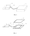
- FIG. 2 shows a diagram of structure decomposition of the first embodiment of the present utility model, comprising the housing 11, wherein the housing is divided into the upper housing 21 and the lower housing 22, and the mainboard assembly 23 configured within the housing 11, further comprising: the USB component 12 in which the heat source module is configured, and the straight plug 13 is configured at the front end of the USB component 12, wherein said USB component 12 and said housing 11 are connected through the rotational shaft 24, further comprising the leading wire 25 of said USB component 12 to connect the heat source module with the mainboard assembly 23, and said leading wire 25 is led from the center of the rotational shaft 24 and is connected to the contact point 26 of the mainboard assembly 23.
- FIG. 3 shows a schematic diagram of the external structure of the second embodiment of the present utility model, and in the present embodiment, it comprises the housing 11, and the mainboard assembly configured within said housing 11, and it further comprises: the USB component 12 in which the heat source module is configured, wherein the straight plug 13 is configured at the front end of the USB component 12, and the difference is that the USB component 12 and the housing 11 are connected through the cable 31, and said cable 31 on the one hand plays the role of physically connecting the USB component 12 and the housing 11, and on the other hand it is also the electrical connection wire between the heat source module and the mainboard assembly 23.
- FIG. 4 is the exploded view of FIG. 3 , and it further illustrates the internal structure of the housing 11 and the wiring mode, comprising the housing 11 and the mainboard assembly provided within the housing 11, further comprising: the USB component 12 in which the heat source module is configured, and the straight plug 13 is provided at the front end of the USB component 12, wherein the housing 11 comprises the upper housing 21 and the lower housing 22, and the mainboard assembly 23 provided within the housing 11, further comprising: the USB component 12 in which the heat source module is configured, and the heat source module and the mainboard assembly 23 are connected to the contact point 41 on the mainboard assembly 23 through the signal leading wire 31.
- Said signal leading wire 31 can be a cable.
- FIG. 1 to FIG. 4 only show two external structure diagrams according to the embodiments of the present utility model, of course there are also other external structures, for example: the push-pull structure is used between the USB component and the housing, and when idle, the USB component can be retracted inside the housing, and when the device is in use, the USB component is pushed out, and no matter what appearance is applied, as long as the scheme is consistent with the technical solution of the embodiment of the present utility model, it should belong to the protection scope of the present utility model.
- the push-pull structure is used between the USB component and the housing, and when idle, the USB component can be retracted inside the housing, and when the device is in use, the USB component is pushed out, and no matter what appearance is applied, as long as the scheme is consistent with the technical solution of the embodiment of the present utility model, it should belong to the protection scope of the present utility model.
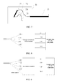
- FIG. 5 is a schematic diagram of the USB component 12 in the first embodiment of the present utility model, comprising: the USB component body 51, the USB straight plug 13 provided at the front end, and said USB component body 51 is connected to the housing of the wireless communication terminal via the rotational shaft 24, and the signal leading wire 25 connecting the heat source module with the mainboard assembly within the USB component body 51 extends to the outside of the USB component body 51 through the center of the rotational shaft 24, and the leading wire 25 may be a general wire, or may also be of the flexible printed circuit (FPC) material.
- FPC flexible printed circuit
- Said heat source module comprises a voltage conversion module, an electrostatic protection circuit unit, a power management circuit unit and a baseband chip, and said electrostatic protection circuit unit, said power management circuit unit and said baseband chip are integrated with said voltage conversion module on the same circuit board.
- said circuit board is specifically a PCB or a thick film circuit board.
- FIG. 6 shows the structure of the USB component in accordance with the second embodiment of the present utility model, comprising the USB straight plug 13, the USB component body 62 and the signal leading wire 31 connecting the heat source module with the mainboard assembly within the USB component body, and the leading wire 31 extends to the outside of the USB component body and is connected with the main body in the housing, wherein the heat source module is shown in FIG. 5 and is not repeated here.
- the signal leading wire 31 can be a cable.
- FIG. 7 is a cross-sectional view of the USB component in accordance with the first embodiment of the present utility model, and shows the mounting mode and the wire connection mode of the heat source module inside the USB component, in FIG. 7 , it comprises: the USB component body 51, the USB straight plug 13, the heat source module 71 and the connecting wire 72 connecting the heat source module 71 and the USB straight plug 13, and in the present embodiment, said connecting wire 72 is specifically a wire or FPC, of course, other connection modes may be used, for example, the straight plug and the heat source module are configured on the same PCB board and are connected with lines configured on said PCB board; wherein, the USB component body 51 is connected to the housing of the wireless communication terminal via the rotational shaft 24, and the signal leading wire 25 connecting the heat source module with the mainboard assembly within the USB component body 51 extends to the outside of the USB component body 51 through the center of rotational shaft 24. Specifically, the USB component body and the housing are mechanically connected or connected with cables, and they are connected via the rotational shaft in the present embodiment, to achieve the
- FIG. 8 is a diagram showing the internal wiring of the USB component in accordance with the first embodiment of the present utility model, wherein the four signals 5V, USB-, USB+ and GND of the straight plug of USB component are connected to the voltage conversion circuit module in the heat source module, and the voltage conversion circuit module converts 5V to VPH, and said VPH may be 3.6V or other voltage values, and the USB- and USB+ are connected to the voltage conversion circuit module to perform electrostatic protection and filtering, and then VPH, USB-, USB+ and GND are bundled together as one leading wire extending to the outside of the USB component, and said leading wire can be the wire or flexible printed circuit (FPC).
- FPC flexible printed circuit
- FIG. 9 is a diagram showing the internal wiring of the USB component in accordance with the second embodiment of the present utility model, and different from the internal wiring shown in FIG. 8 , besides the signals VPH, USB-, USB+ and GND, there are other signals in the leading wire of the voltage conversion circuit module.
- the leading wire of the heat source module may also comprise other signal lines besides the power supply and the USB signal.
- FIG. 8 and FIG. 9 only show two internal wiring modes of the USB component, and of course, there are other wiring modes, for example, the USB- and USB+ do not pass through the DCDC voltage conversion circuit module, but go directly across the DCDC voltage conversion circuit module and are bundled with VPH and GND as one leading wire extending to the outside of the USB component, regardless of the wiring mode, as long as the technical solution is consistent with the technical solution of the embodiment of the present utility model, it should belong to the protection scope of the present utility model.
- the wireless communication terminal provided in the embodiment of the present utility model has a small, tiny and beautiful structure whose surface temperature is lowered, thus greatly improving the user experience; in addition, the structure of the wireless communication terminal provided in the embodiment of the present utility model is simple, easy to be implemented, and it does not additionally increase the cost. Therefore, the present utility model has a strong industrial applicability.
Landscapes
- Engineering & Computer Science (AREA)
- Microelectronics & Electronic Packaging (AREA)
- Theoretical Computer Science (AREA)
- Computer Hardware Design (AREA)
- Human Computer Interaction (AREA)
- Physics & Mathematics (AREA)
- General Engineering & Computer Science (AREA)
- General Physics & Mathematics (AREA)
- Cooling Or The Like Of Electrical Apparatus (AREA)
- Transceivers (AREA)
- Telephone Set Structure (AREA)
- Arrangements For Transmission Of Measured Signals (AREA)
Applications Claiming Priority (2)
| Application Number | Priority Date | Filing Date | Title |
|---|---|---|---|
| CN2012201587090U CN202736489U (zh) | 2012-04-16 | 2012-04-16 | 一种无线通讯终端 |
| PCT/CN2012/078674 WO2013155802A1 (fr) | 2012-04-16 | 2012-07-16 | Terminal de communication sans fil |
Publications (2)
| Publication Number | Publication Date |
|---|---|
| EP2819021A1 true EP2819021A1 (fr) | 2014-12-31 |
| EP2819021A4 EP2819021A4 (fr) | 2015-05-06 |
Family
ID=47662164
Family Applications (1)
| Application Number | Title | Priority Date | Filing Date |
|---|---|---|---|
| EP12874514.8A Withdrawn EP2819021A4 (fr) | 2012-04-16 | 2012-07-16 | Terminal de communication sans fil |
Country Status (7)
| Country | Link |
|---|---|
| US (1) | US20150070809A1 (fr) |
| EP (1) | EP2819021A4 (fr) |
| JP (1) | JP5947452B2 (fr) |
| CN (1) | CN202736489U (fr) |
| AU (1) | AU2012377229A1 (fr) |
| RU (1) | RU2592397C2 (fr) |
| WO (1) | WO2013155802A1 (fr) |
Cited By (1)
| Publication number | Priority date | Publication date | Assignee | Title |
|---|---|---|---|---|
| CN113791679A (zh) * | 2021-09-29 | 2021-12-14 | 深圳市智仁科技有限公司 | 一种具有自启动功能的嵌入式主板系统及方法 |
Families Citing this family (2)
| Publication number | Priority date | Publication date | Assignee | Title |
|---|---|---|---|---|
| CN111328230B (zh) * | 2020-03-31 | 2025-03-25 | 广州视源电子科技股份有限公司 | 无线传屏装置 |
| CN112307523B (zh) * | 2020-11-09 | 2024-09-24 | 维沃移动通信有限公司 | 芯片模组、信息处理方法、装置及电子设备 |
Family Cites Families (17)
| Publication number | Priority date | Publication date | Assignee | Title |
|---|---|---|---|---|
| ES2285812T3 (es) * | 1998-11-10 | 2007-11-16 | Aladdin Knowledge Systems Ltd. | Metodo de interaccion usuario-ordenador para ser usado por sistemas de ordenador conectables de forma flexible. |
| JP2004171427A (ja) * | 2002-11-22 | 2004-06-17 | Sourcenext Corp | USB(UniversalSerialBus)ケーブル |
| TWM277043U (en) * | 2005-04-27 | 2005-10-01 | Wing Span Entpr Co Ltd | PC card structure with of USB connector ports and interfaces |
| JP4603957B2 (ja) * | 2005-08-26 | 2010-12-22 | キヤノン株式会社 | 無線装置 |
| DE602005013394D1 (de) * | 2005-11-11 | 2009-04-30 | Lite On Technology Corp | Kühlung von einem kleinen elektronischen Gerät mit einem USB Verbinder. |
| JP2007156682A (ja) * | 2005-12-02 | 2007-06-21 | Toshiba Corp | 携帯型記憶装置 |
| US8058840B2 (en) * | 2006-05-25 | 2011-11-15 | Moxia Energy Holdings Limited | Rechargeable battery assembly with movable connector and power conversion circuitry |
| CN201114118Y (zh) * | 2007-10-24 | 2008-09-10 | 中兴通讯股份有限公司 | 一种具有usb接口的数据卡 |
| CN101242047B (zh) * | 2008-02-26 | 2010-06-09 | 华为终端有限公司 | Usb连接件及usb装置 |
| TWI355576B (en) * | 2009-02-20 | 2012-01-01 | Quanta Comp Inc | Electronic device |
| TWM364398U (en) * | 2009-05-18 | 2009-09-01 | Quanta Comp Inc | Electronic device |
| CN101609954B (zh) * | 2009-07-16 | 2011-04-06 | 中兴通讯股份有限公司 | 一种双转轴旋转无线网卡 |
| CN101969264B (zh) * | 2009-07-28 | 2012-10-17 | 联芯科技有限公司 | 一种电源供电方法、装置及系统 |
| CN101674674B (zh) * | 2009-09-18 | 2013-09-11 | 华为终端有限公司 | 无线终端设备 |
| CN101694596A (zh) * | 2009-10-29 | 2010-04-14 | 深圳华为通信技术有限公司 | 数据卡的供电芯片和数据卡 |
| CN201718153U (zh) * | 2010-06-11 | 2011-01-19 | 华为终端有限公司 | 一种旋转数据卡 |
| CN101964711B (zh) * | 2010-09-20 | 2013-01-16 | 华为终端有限公司 | 数据卡的供电电路、供电芯片及数据卡 |
-
2012
- 2012-04-16 CN CN2012201587090U patent/CN202736489U/zh not_active Expired - Lifetime
- 2012-07-16 EP EP12874514.8A patent/EP2819021A4/fr not_active Withdrawn
- 2012-07-16 RU RU2014141527/08A patent/RU2592397C2/ru active
- 2012-07-16 AU AU2012377229A patent/AU2012377229A1/en not_active Abandoned
- 2012-07-16 JP JP2015506074A patent/JP5947452B2/ja not_active Expired - Fee Related
- 2012-07-16 WO PCT/CN2012/078674 patent/WO2013155802A1/fr not_active Ceased
- 2012-07-16 US US14/389,842 patent/US20150070809A1/en not_active Abandoned
Cited By (2)
| Publication number | Priority date | Publication date | Assignee | Title |
|---|---|---|---|---|
| CN113791679A (zh) * | 2021-09-29 | 2021-12-14 | 深圳市智仁科技有限公司 | 一种具有自启动功能的嵌入式主板系统及方法 |
| CN113791679B (zh) * | 2021-09-29 | 2022-04-19 | 深圳市智仁科技有限公司 | 一种具有自启动功能的嵌入式主板系统及方法 |
Also Published As
| Publication number | Publication date |
|---|---|
| RU2014141527A (ru) | 2016-05-10 |
| WO2013155802A1 (fr) | 2013-10-24 |
| JP5947452B2 (ja) | 2016-07-06 |
| EP2819021A4 (fr) | 2015-05-06 |
| RU2592397C2 (ru) | 2016-07-20 |
| US20150070809A1 (en) | 2015-03-12 |
| CN202736489U (zh) | 2013-02-13 |
| AU2012377229A1 (en) | 2014-10-30 |
| JP2015516771A (ja) | 2015-06-11 |
Similar Documents
| Publication | Publication Date | Title |
|---|---|---|
| US8040686B2 (en) | Power supply apparatus having DC-DC converter module mounted on individual printed circuit board | |
| CN207200326U (zh) | 低功耗唤醒电路、供电控制器、供电装置和电动工具 | |
| EP2819021A1 (fr) | Terminal de communication sans fil | |
| CN107490161A (zh) | 控制盒组件与空调器 | |
| CN102955546A (zh) | 电脑对外接设备的供电电路 | |
| CN201918590U (zh) | Usb连接线 | |
| CN103001081A (zh) | 一种新型usb集线器 | |
| CN209913724U (zh) | 一种多功能电源适配器 | |
| CN203102090U (zh) | 一种带有移动电源的多功能平板电脑保护套 | |
| CN201167284Y (zh) | 单元变频器 | |
| CN211959675U (zh) | 一种基于锂电池的电动文具专用电路板 | |
| CN203871999U (zh) | 包含发电机emc电路的汽车发电机后壳 | |
| CN2833684Y (zh) | 配置于摩托车的多功能电源插座 | |
| CN204795861U (zh) | 无线路由器电路板 | |
| CN223625765U (zh) | 一种多功能电源转换器 | |
| CN219739114U (zh) | 带外部接口的替铅电池包 | |
| CN203250953U (zh) | 一种便携式多功能电源 | |
| CN203617879U (zh) | 适配器电源 | |
| CN214254886U (zh) | 一种防脱落电源适配器 | |
| CN202771297U (zh) | 集成低压差三端稳压器的安装结构 | |
| CN217468967U (zh) | 电动升降插座 | |
| CN202997049U (zh) | 一种含触压接口的柔性电路板天线 | |
| CN202513225U (zh) | 一种电池电极接触组件 | |
| CN201252306Y (zh) | 将计算机内电源引出机外供其他设备使用的电源供应装置 | |
| KR200305622Y1 (ko) | 직류 잭과 유에스비 잭을 장착한 커넥터 |
Legal Events
| Date | Code | Title | Description |
|---|---|---|---|
| PUAI | Public reference made under article 153(3) epc to a published international application that has entered the european phase |
Free format text: ORIGINAL CODE: 0009012 |
|
| 17P | Request for examination filed |
Effective date: 20140926 |
|
| AK | Designated contracting states |
Kind code of ref document: A1 Designated state(s): AL AT BE BG CH CY CZ DE DK EE ES FI FR GB GR HR HU IE IS IT LI LT LU LV MC MK MT NL NO PL PT RO RS SE SI SK SM TR |
|
| AX | Request for extension of the european patent |
Extension state: BA ME |
|
| RA4 | Supplementary search report drawn up and despatched (corrected) |
Effective date: 20150410 |
|
| RIC1 | Information provided on ipc code assigned before grant |
Ipc: G06F 1/20 20060101ALI20150405BHEP Ipc: G11C 7/24 20060101ALI20150405BHEP Ipc: H04L 12/02 20060101ALI20150405BHEP Ipc: H05K 5/02 20060101ALI20150405BHEP Ipc: G06F 13/00 20060101AFI20150405BHEP |
|
| DAX | Request for extension of the european patent (deleted) | ||
| STAA | Information on the status of an ep patent application or granted ep patent |
Free format text: STATUS: EXAMINATION IS IN PROGRESS |
|
| 17Q | First examination report despatched |
Effective date: 20181023 |
|
| STAA | Information on the status of an ep patent application or granted ep patent |
Free format text: STATUS: THE APPLICATION HAS BEEN WITHDRAWN |
|
| 18W | Application withdrawn |
Effective date: 20190205 |