EP2819325B1 - Verteiltes basisstations-signalübertragungssystem und kommunikationssystem - Google Patents
Verteiltes basisstations-signalübertragungssystem und kommunikationssystem Download PDFInfo
- Publication number
- EP2819325B1 EP2819325B1 EP13798015.7A EP13798015A EP2819325B1 EP 2819325 B1 EP2819325 B1 EP 2819325B1 EP 13798015 A EP13798015 A EP 13798015A EP 2819325 B1 EP2819325 B1 EP 2819325B1
- Authority
- EP
- European Patent Office
- Prior art keywords
- signal
- multiplexing
- optical module
- demultiplexing unit
- colorless optical
- Prior art date
- Legal status (The legal status is an assumption and is not a legal conclusion. Google has not performed a legal analysis and makes no representation as to the accuracy of the status listed.)
- Active
Links
Images



Classifications
-
- H—ELECTRICITY
- H04—ELECTRIC COMMUNICATION TECHNIQUE
- H04B—TRANSMISSION
- H04B10/00—Transmission systems employing electromagnetic waves other than radio-waves, e.g. infrared, visible or ultraviolet light, or employing corpuscular radiation, e.g. quantum communication
- H04B10/25—Arrangements specific to fibre transmission
- H04B10/2575—Radio-over-fibre, e.g. radio frequency signal modulated onto an optical carrier
- H04B10/25752—Optical arrangements for wireless networks
- H04B10/25758—Optical arrangements for wireless networks between a central unit and a single remote unit by means of an optical fibre
-
- H—ELECTRICITY
- H04—ELECTRIC COMMUNICATION TECHNIQUE
- H04B—TRANSMISSION
- H04B10/00—Transmission systems employing electromagnetic waves other than radio-waves, e.g. infrared, visible or ultraviolet light, or employing corpuscular radiation, e.g. quantum communication
- H04B10/25—Arrangements specific to fibre transmission
-
- H—ELECTRICITY
- H04—ELECTRIC COMMUNICATION TECHNIQUE
- H04B—TRANSMISSION
- H04B10/00—Transmission systems employing electromagnetic waves other than radio-waves, e.g. infrared, visible or ultraviolet light, or employing corpuscular radiation, e.g. quantum communication
- H04B10/25—Arrangements specific to fibre transmission
- H04B10/2575—Radio-over-fibre, e.g. radio frequency signal modulated onto an optical carrier
- H04B10/25752—Optical arrangements for wireless networks
-
- H—ELECTRICITY
- H04—ELECTRIC COMMUNICATION TECHNIQUE
- H04B—TRANSMISSION
- H04B10/00—Transmission systems employing electromagnetic waves other than radio-waves, e.g. infrared, visible or ultraviolet light, or employing corpuscular radiation, e.g. quantum communication
- H04B10/27—Arrangements for networking
-
- H—ELECTRICITY
- H04—ELECTRIC COMMUNICATION TECHNIQUE
- H04J—MULTIPLEX COMMUNICATION
- H04J14/00—Optical multiplex systems
- H04J14/02—Wavelength-division multiplex systems
- H04J14/0227—Operation, administration, maintenance or provisioning [OAMP] of WDM networks, e.g. media access, routing or wavelength allocation
- H04J14/0241—Wavelength allocation for communications one-to-one, e.g. unicasting wavelengths
- H04J14/0242—Wavelength allocation for communications one-to-one, e.g. unicasting wavelengths in WDM-PON
- H04J14/0245—Wavelength allocation for communications one-to-one, e.g. unicasting wavelengths in WDM-PON for downstream transmission, e.g. optical line terminal [OLT] to ONU
- H04J14/0246—Wavelength allocation for communications one-to-one, e.g. unicasting wavelengths in WDM-PON for downstream transmission, e.g. optical line terminal [OLT] to ONU using one wavelength per ONU
-
- H—ELECTRICITY
- H04—ELECTRIC COMMUNICATION TECHNIQUE
- H04J—MULTIPLEX COMMUNICATION
- H04J14/00—Optical multiplex systems
- H04J14/02—Wavelength-division multiplex systems
- H04J14/0227—Operation, administration, maintenance or provisioning [OAMP] of WDM networks, e.g. media access, routing or wavelength allocation
- H04J14/0241—Wavelength allocation for communications one-to-one, e.g. unicasting wavelengths
- H04J14/0242—Wavelength allocation for communications one-to-one, e.g. unicasting wavelengths in WDM-PON
- H04J14/0249—Wavelength allocation for communications one-to-one, e.g. unicasting wavelengths in WDM-PON for upstream transmission, e.g. ONU-to-OLT or ONU-to-ONU
- H04J14/025—Wavelength allocation for communications one-to-one, e.g. unicasting wavelengths in WDM-PON for upstream transmission, e.g. ONU-to-OLT or ONU-to-ONU using one wavelength per ONU, e.g. for transmissions from-ONU-to-OLT or from-ONU-to-ONU
-
- H—ELECTRICITY
- H04—ELECTRIC COMMUNICATION TECHNIQUE
- H04J—MULTIPLEX COMMUNICATION
- H04J14/00—Optical multiplex systems
- H04J14/02—Wavelength-division multiplex systems
- H04J14/0278—WDM optical network architectures
- H04J14/0279—WDM point-to-point architectures
-
- H—ELECTRICITY
- H04—ELECTRIC COMMUNICATION TECHNIQUE
- H04J—MULTIPLEX COMMUNICATION
- H04J14/00—Optical multiplex systems
- H04J14/02—Wavelength-division multiplex systems
- H04J14/0278—WDM optical network architectures
- H04J14/0282—WDM tree architectures
-
- H—ELECTRICITY
- H04—ELECTRIC COMMUNICATION TECHNIQUE
- H04J—MULTIPLEX COMMUNICATION
- H04J14/00—Optical multiplex systems
- H04J14/02—Wavelength-division multiplex systems
- H04J14/0227—Operation, administration, maintenance or provisioning [OAMP] of WDM networks, e.g. media access, routing or wavelength allocation
- H04J14/0241—Wavelength allocation for communications one-to-one, e.g. unicasting wavelengths
- H04J14/0242—Wavelength allocation for communications one-to-one, e.g. unicasting wavelengths in WDM-PON
- H04J2014/0253—Allocation of downstream wavelengths for upstream transmission
Definitions
- the present invention relates to the field of communications, and in particular, to a distributed base station signal transmission system and a communication system.
- EP 2 144 388 A2 refers to a hybrid network optical communication system.
- the system may include a central office and at least one network group coupled to the central office.
- the network group may include a plurality of external rings, and each of the external rings may include a plurality of nodes having a ring connection.
- US 2011/0033187 A1 refers in an example embodiment to a dual split passive optical network (PON) that includes an optical splitting device, and a first and second distribution fibers connected to the optical splitting device.
- a first cyclic AWG may be coupled to the optical splitting device via the first distribution fiber and a second cyclic AWG may be coupled to the optical splitting device via the second distribution fiber.
- an asymmetric power splitting ratio may be used for the splitting device, or optical seeds and/or optical data signals may be allocated to each of the cyclic AWGs based on a performance of the optical data signals and/or power loss/attenuation of the respective distribution fibers.
- XP 008090837 refers to a low-cost WDM-PON with colorless bidirectional transceivers.
- WO 2011/018054 A1 refers to an apparatus comprising a plurality of laser transmitters each comprising a polarization rotator, a polarization rotator mirror coupled to the laser transmitters, and a multiplexer positioned between the laser transmitters and the polarization rotator mirror. Also included is an apparatus comprising a first rotator configured to rotate light polarization by about 45 or about - 45 degrees, a second rotator configured to rotate light polarization by about 45 or about -45 degrees, a mirror coupled to one side of the second rotator and configured to reflect at least a portion of the light, and a wavelength division multiplexing (WDM) filter positioned between the first rotator and the second rotator.
- WDM wavelength division multiplexing
- XP 32173997 refers to a infrastructure for convergence of radio, fibre and DSL technologies.
- US 2012/0106963 A1 discloses a system, a method and a related device for signal transmission in order to improve utilization efficiency of the fiber.
- the system includes an optical line terminal (OLT), a plurality of optical network units (ONU), a base band unit (BBU), a plurality of remote radio units (RRU), a first signal-processing device and a plurality of second signal-processing devices, wherein the first signal-processing device sends a multiplexed signal to a plurality of second signal-processing devices after a plurality of signals sent by the OLT and the BBU are multiplexed, and demultiplexes a signal sent by the second signal-processing device in order to obtain a plurality of signals sent by the ONU and a plurality of different RRUs and sends these demultiplexed signals to the OLT and the BBU.
- OLT optical line terminal
- ONU optical network units
- BBU base band unit
- RRU remote radio units
- One of a plurality of second signal processing devices sends a multiplexed signal to the first signal-processing device after a plurality of signals sent by the ONU and a plurality of different RRUs are multiplexed, and demultiplexes a signal sent by the first signal-processing device in order to obtain a signal sent by the OLT and a plurality of signals sent to a plurality of different RRUs by the BBU and sends these demultiplexed signals to the ONU and the RRUs.
- a distributed base station compared with a conventional macro base station, is divided into a Base Band Unit (BBU) and a Remote Radio Unit (RRU).
- BBU Base Band Unit
- RRU Remote Radio Unit
- BBU Base Band Unit
- RRU Remote Radio Unit
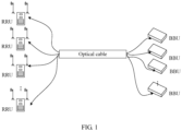
- a first method is using fibers for connection, that is, using fibers to directly connect BBUs and RRUs, and a network structure thereof is illustrated in FIG. 1 .
- the network structure is simple, but many fiber resources need to be occupied. Therefore, the method is inapplicable to a scenario where fiber resources are insufficient, and features a high cost.
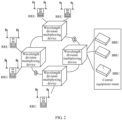
- a second method is using a metro wavelength division multiplexing (WDM) network for bearing, that is, using a metro wavelength division multiplexing network to bear a Common Public Radio Interface (CPRI) service between BBUs and RRUs, and a network structure thereof is illustrated in FIG. 2 .
- the method uses an existing metro wavelength division multiplexing device to bear services, features high reliability, and is flexible in networking and service upgrade.
- the method requires that the wavelength division multiplexing device is placed in a dedicated outdoor cabinet or a wavelength division multiplexing device suitable for an outdoor scenario is developed separately, and features a high cost in networking. Therefore, a problem of large resource consumption and high costs in interconnection between BBUs and RRUs exists in the prior art.
- An objective of embodiments of the present invention is to provide a distributed base station signal transmission system, in order to solve a problem of large resource consumption and high costs in interconnection between BBUs and RRUs in the prior art.
- a first multiplexing and demultiplexing unit and a second multiplexing and demultiplexing unit respectively multiplex signals transmitted by a BBU and an RRU, and output the signals to each other
- uplink and downlink multiplexed signals are transmitted between the first multiplexing and demultiplexing unit and the second multiplexing and demultiplexing unit, where the uplink and downlink multiplexed signals each require one fiber for transmission, and the uplink and downlink multiplexed signals may also be transmitted in a same fiber.
- the embodiments of the present invention only one trunk fiber or a pair of trunk fibers is required, and it is unnecessary to use a large number of fibers to interconnect BBUs and RRUs one by one, and unnecessary to use an expensive metro wavelength division multiplexing network for bearing services.
- the embodiments are applicable to a scenario where fiber resources are insufficient, facilitate network construction, and significantly save costs.
- a colorless optical module is used to generate a downlink or uplink signal.
- a colorless optical module can provide a random wavelength, and different BBUs and RRUs may be configured with a same type of colorless optical module, which has high adaptability, is easy to install and maintain, and significantly saves a networking cost.
- the system may be implemented based on the existing network architecture, and may reuse fiber resources in an existing passive optical transmission system to interconnect the BBUs and the RRUs, thereby significantly simplifying network construction and saving costs.
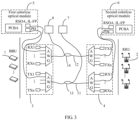
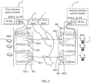
- FIG. 3 to FIG. 5 are schematic structural diagrams of a distributed base station signal transmission system according to Embodiment 1 not part of the present invention. For ease of description, only parts related to the embodiment are illustrated.
- the distributed base station signal transmission system includes a BBU1 and a RRU2, where the system further includes a first multiplexing and demultiplexing unit 3, a second multiplexing and demultiplexing unit 4, a first colorless optical module 5, a second colorless optical module 6, a first broad-spectrum light source 7, and a second broad-spectrum light source 8.
- the first multiplexing and demultiplexing unit 3 transmits signals with the base band unit 1 by using the first colorless optical module 5.
- the second multiplexing and demultiplexing unit 4 transmits signals with the remote radio unit 2 by using the second colorless optical module 6. Multiplex signals are transmitted between the first multiplexing and demultiplexing unit 3 and the second multiplexing and demultiplexing unit 4.
- the first broad-spectrum light source 7 outputs a broad-spectrum optical signal to the first multiplexing and demultiplexing unit 3, where the broad-spectrum optical signal, after being filtered by the first multiplexing and demultiplexing unit 3, is divided into a variety of monochromatic waves or a variety of narrowband light waves, so as to provide exciting light for the corresponding first colorless optical module 5.
- the first colorless optical module 5 under modulation of an electrical signal transmitted by the BBU 1, generates a downlink signal whose wavelength is the same as that of the exciting light.
- the downlink signal, after being multiplexed by the first multiplexing and demultiplexing unit 3, is output to the RRU 2.
- the second multiplexing and demultiplexing unit 4 at the RRU 2 side demultiplexes the multiplexed downlink signal, and the demultiplexed downlink signal, after being parsed by the second colorless optical module 6, is finally transmitted to the RRU 2, thereby completing signal transmission from the BBU 1 to the RRU 2.
- the second broad-spectrum light source 8 outputs a broad-spectrum optical signal to the second multiplexing and demultiplexing unit 4, where the broad-spectrum optical signal, after being filtered by the second multiplexing and demultiplexing unit 4, is divided into a variety of monochromatic waves or a variety of narrowband light waves, so as to provide exciting light for the corresponding second colorless optical module 6, and the second colorless optical module 6, under modulation of an electrical signal transmitted by the RRU 2, generates an uplink signal whose wavelength is the same as that of the exciting light.
- the uplink signal after being multiplexed by the second multiplexing and demultiplexing unit 4, is output to the BBU 1, the first multiplexing and demultiplexing unit 3 at the BBU 1 side demultiplexes the multiplexed uplink signal, and the demultiplexed uplink signal, after being parsed by the first colorless optical module 5, is finally transmitted to the BBU 1, thereby completing signal transmission from the RRU 2 to the BBU 1. In this way, interconnection between the BBU 1 and the RRU 2 is implemented.
- a first multiplexing and demultiplexing unit 3 and a second multiplexing and demultiplexing unit 4 respectively multiplex signals transmitted by a BBU 1 and an RRU 2 which are respectively connected to the first multiplexing and demultiplexing unit 3 and the second multiplexing and demultiplexing unit 4, and output the signals to each other
- uplink and downlink multiplexed signals are transmitted between the first multiplexing and demultiplexing unit 3 and the second multiplexing and demultiplexing unit 4, where the uplink and downlink multiplexed signals each require one fiber for transmission, and the uplink and downlink multiplexed signals may even be transmitted in a same fiber.
- the embodiment of the present invention it is unnecessary to use a large number of fibers to interconnect BBUs 1 and RRUs 2 one by one, and unnecessary to use an expensive metro wavelength division multiplexing network for bearing services.
- the embodiment is not only applicable to a scenario where fiber resources are insufficient, but also facilitates network construction and significantly saves costs.
- the system may be implemented based on an existing network architecture, and may use fiber resources in an existing passive optical network (and an existing multiplexing and demultiplexing device) to transmit an uplink or downlink signal, thereby further simplifying network construction and saving costs.
- an optical signal is injected by an external broad-spectrum light source; a first colorless optical module and a second colorless optical module are used to generate a downlink signal and an uplink signal.
- a colorless optical module may provide a signal of a random wavelength, and no matter which service band is used by the BBU and RRU, a same type of colorless optical module may be configured, which has high adaptability, is easy to install and maintain, and significantly saves a networking cost.
- the first colorless optical module 5 may be embedded in the BBU 1
- the second colorless optical module 6 may be embedded in the RRU 2.
- the uplink signal and the downlink signal use different bands, may respectively use L-band (1570.42 nm to 1603.57 nm or 190.90 THz to 186.95 THz) and C-band (1529.16 nm to 1560.61 nm or 196.05 THz to 192.10 THz), or respectively use two different sub-bands of L-band or C-band.
- types of the first and second multiplexing and demultiplexing units and specific composition structures thereof may be determined according to the specific bands which are used by the uplink signal and the downlink signal.
- a multiplexing and demultiplexing device can implement wavelength division multiplexing for a certain bandwidth, for example, L-band or C-band, but cannot implement multiplexing for a band whose bandwidth is too broad, for example, a relatively broad band including L-band and C-band.
- the first multiplexing and demultiplexing unit 3 and the second multiplexing and demultiplexing unit 4 may be formed by one multiplexing and demultiplexing device each; when the uplink signal and the downlink signal respectively use L-band and C-band, the first and second multiplexing and demultiplexing units may preferably be formed by two multiplexing and demultiplexing devices each, in order to satisfy a service requirement of a relatively broad band.
- the uplink signal and the downlink signal respectively use L-band and C-band, which have relatively large capacities, facilitates signal transmission, and facilitates configuration of a broad-spectrum light source.
- the first multiplexing and demultiplexing unit 3 may be formed by two multiplexing and demultiplexing devices, where one of the two devices is a first transmitting end device 301, which may multiplex and output a C-band downlink signal, and the other is a first receiving end device 302, which may receive and demultiplex an L-band uplink signal.
- the first transmitting end device 301 has a first common port 3011
- the first receiving end device 302 has a second common port 3021.
- the first transmitting end device 301 outputs the multiplexed downlink signal through the first common port 3011, and the first receiving end device 302 receives the multiplexed uplink signal through the second common port 3021.
- the second multiplexing and demultiplexing unit 4 is formed by two multiplexing and demultiplexing devices, where one of the two devices is a second transmitting end device 401, which may multiplex and output an L-band uplink signal, and the other is a second receiving end device 402, which may receive and demultiplex a C-band downlink signal.
- the second transmitting end device 401 has a third common port 4011, and the second receiving end device 402 has a fourth common port 4021.
- the second transmitting end device 401 outputs the multiplexed uplink signal through the third common port 4011, and the second receiving end device 402 receives the multiplexed downlink signal through the fourth common port 4021.
- the first multiplexing and demultiplexing unit 3 also includes multiple branch ports.
- the first transmitting end device 301 has multiple first branch ports 3012, which are correspondingly connected to multiple first colorless optical modules 5 in a one-to-one manner, and further downlink signals generated by the first colorless optical modules 5 may be transmitted to the first transmitting end device 301, multiplexed by the first transmitting end device 301, and output through the first common port 3011, thereby implementing multiplexing and outputting of the downlink signals.
- the first receiving end device 302 has multiple second branch ports 3022, which are correspondingly connected to multiple first colorless optical modules 5 in a one-to-one manner, and uplink signals demultiplexed by the first receiving end device 302 are transmitted to the corresponding first colorless optical modules 5, thereby implementing receiving and parsing of the uplink signals.
- the second multiplexing and demultiplexing unit 4 also includes multiple branch ports.
- the second transmitting end device 401 has multiple third branch ports 4012
- the second receiving end device 402 has multiple fourth branch ports 4022, which are all correspondingly connected to the second colorless optical modules 6 in a one-to-one manner.
- Uplink signals generated by the second colorless optical modules 6 may be transmitted to the second transmitting end device 401 through the corresponding third branch ports 4012, multiplexed by the second transmitting end device 401, and output through the third common port 4011, thereby implementing multiplexing and outputting of the uplink signals.
- the second receiving end device 402 demultiplexes multiplexed downlink signals, and the downlink signals are transmitted to the corresponding second colorless optical modules 6 through the fourth branch ports 4022, thereby implementing receiving and parsing of the downlink signals.
- an uplink signal may also use C-band, and that a downlink signal may use L-band.
- the uplink signal and the downlink signal may also use other bands, which is not strictly limited. In practical networking, it is appropriate to choose multiplexing and demultiplexing units reasonably according to specific bands.
- the first common port 3011 of the first transmitting end device 301 is connected to the fourth common port 4021 of the second receiving end device 402 through a first fiber 11, to provide a transmission path for the downlink signal.
- the second common port 3021 of the first receiving end device 302 is connected to the third common port 4011 of the second transmitting end device 401 through a second fiber 12, to provide a transmission path for the uplink signal. Therefore, only two trunk fibers need to be disposed in the system.
- a coupler may be disposed on the first fiber 11 and the second fiber 12 each.
- the couplers are respectively a first coupler 13 and a second coupler 14.
- the first broad-spectrum light source 7 outputs a broad-spectrum optical signal to the first common port 3011 through the first coupler 13, and the first transmitting end device 301 demultiplexes the broad-spectrum optical signal and outputs the broad-spectrum optical signal to each of the first colorless optical modules 5, to provide exciting light for the first colorless optical module 5, so as to generate a downlink signal.
- the second broad-spectrum light source 8 outputs a broad-spectrum optical signal to the third common port 4011 through the second coupler 14, and the second transmitting end device 401 decomposes the broad-spectrum optical signal to each of the second colorless optical modules 6, so as to generate an uplink signal.
- two WDMs may be added to the system, where both the first common port 3011 and the second common port 3021 are connected to a first wavelength division multiplexer 15, both the third common port 4011 and the fourth common port 4021 are connected to a second wavelength division multiplexer 16, and the first wavelength division multiplexer 15 and the second wavelength division multiplexer 16 are connected by using a single fiber 17.
- an uplink signal band for example, L-band
- a downlink signal band for example, C-band
- the uplink signal band and the downlink signal band can be transmitted in the single fiber 17.
- only one trunk fiber needs to be configured in the system. This solution is particularly applicable to a scenario where fiber resources are insufficient.
- the first broad-spectrum light source 7 and the second broad-spectrum light source 8 may output a broad-spectrum optical signal respectively to the first common port 3011 and the third common port 4011through a same third coupler 18, where the third coupler 18 is disposed on the single fiber 17.
- the WDMs after the WDMs are used, not only fibers are saved, but also the number of used couplers decreases, and further costs are reduced.
- both the first multiplexing and demultiplexing unit 3 and the second multiplexing and demultiplexing unit 4 may use an Array Waveguide Grating (AWG) or an Optical Add-Drop Multiplexer (OADM) formed by optical filters.
- AMG Array Waveguide Grating
- OADM Optical Add-Drop Multiplexer
- both the first colorless optical module 5 and the second colorless optical module 6 include a signal transmitter and a signal receiver, where a Photo Diode (PD) is disposed in the signal receiver.
- a light-emitting medium in the signal transmitter may spontaneously radiate, or may generate an optical signal under an action of exciting light.
- the signal transmitter may use a reflective semi-conductor optical amplifier (RSOA), or may use an injection-locked Fabry-Perot laser (IL-FP) and the like. After the signal transmitter performs modulation by using electrical data from the BBU 1 side, a corresponding downlink signal is generated.
- RSOA reflective semi-conductor optical amplifier
- IL-FP injection-locked Fabry-Perot laser
- the signal receiver in the second colorless optical module 6 of the RRU 2 side parses the downlink signal, and restores data that is carried in the downlink signal, thereby completing data transmission from the BBU 1 to the RRU 2.
- Data transmission from the RRU 2 to the BBU 1 is the same as above.
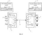
- FIG. 6 is a schematic structural diagram of a distributed base station signal transmission system according to Embodiment 2 of the present invention. For ease of description, only parts related to the embodiment are illustrated.
- a multiplexing and demultiplexing unit 3 in this embodiment may use a cyclic multiplexing and demultiplexing device, which specifically may be a cyclic AWG.
- the cyclic AWG device may input and output both light of C-band and L-band (respectively an uplink band and a downlink band) at a same port. Therefore, by using only one AWG device, transmission of uplink and downlink signals can be implemented through one port, thereby decreasing the number of multiplexing and demultiplexing devices and further saving costs.
- a first multiplexing and demultiplexing unit only includes one common port.
- a fifth common port 31 in this embodiment, where the fifth common port 31 is mainly configured to output a downlink signal multiplexed by a first multiplexing and demultiplexing unit 3 and receive an uplink signal multiplexed and output by a second multiplexing and demultiplexing unit 4.
- the second multiplexing and demultiplexing unit 4 includes a sixth common port 41, which outputs an uplink signal multiplexed by the second multiplexing and demultiplexing unit 4 and receive a downlink signal multiplexed and output by the first multiplexing and demultiplexing unit 3.
- the fifth common port 31 and the sixth common port 41 are still connected by using a single fiber 17.
- a first broad-spectrum light source 7 and a second broad-spectrum light source 8 still output a broad-spectrum optical signal respectively to the fifth common port 31 and the sixth common port 41 through a same third coupler 18, and the broad-spectrum optical signal is output to a corresponding colorless optical module through the multiplexing and demultiplexing unit.
- the first multiplexing and demultiplexing unit 3 also has several branch ports that may perform input and output at the same time, for example, C1-band and L1-band signals are transmitted upward and downward respectively through one branch port, C2-band and L2-band signals are transmitted upward and downward respectively through another branch port, and so on.
- the first multiplexing and demultiplexing unit 3 in the embodiment further includes fifth branch ports 32, which are correspondingly connected to first colorless optical modules 5 in a one-to-one manner, and transmit downlink signals generated by the first colorless optical modules 5 to the first multiplexing and demultiplexing unit 3 and transmit uplink signals demultiplexed by the first multiplexing and demultiplexing unit 3 to the corresponding first colorless optical modules 5.
- the second multiplexing and demultiplexing unit 4 further includes sixth branch ports 42, which are correspondingly connected to second colorless optical modules 6 in a one-to-one manner, and configured to transmit uplink signals generated by the second colorless optical modules 6 to the second multiplexing and demultiplexing unit 4 and transmit downlink signals demultiplexed by the second multiplexing and demultiplexing unit 4 to the corresponding second colorless optical modules 6.
- a wavelength division multiplexer is disposed in the first colorless optical module 5 and the second colorless optical module 6 each.
- the wavelength division multiplexers are respectively a third wavelength division multiplexer 19 and a fourth wavelength division multiplexer 20, where one end of the third wavelength division multiplexer 19 is connected to a corresponding fifth branch port 32, and the other end is connected to a signal transmitter and a signal receiver in the first colorless optical module 5, and the third wavelength division multiplexer 19 is configured to combine or divide uplink and downlink signals.
- one end of the fourth wavelength division multiplexer 20 is connected to a corresponding sixth branch port 42, and the other end is connected to a signal transmitter and a signal receiver in the second colorless optical module 6.
- the number of multiplexing and demultiplexing devices decreases, and only one trunk fiber is required to perform transmission. Therefore, the system structure is simpler and costs are lower.
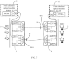
- FIG. 7 and FIG. 8 are schematic structural diagrams of a distributed base station signal transmission system according to Embodiment 3 not part of the present invention. For ease of description, only parts related to the embodiment are illustrated.
- the distributed base station signal transmission system provided in the embodiment of the present invention is largely the same as the system described in the foregoing Embodiment 1.
- the system provided in the embodiment of the present invention includes a BBU1 and a RRU 2, and further includes a first multiplexing and demultiplexing unit 3, a second multiplexing and demultiplexing unit 4, a first colorless optical module 5, and a second colorless optical module 6.
- the foregoing devices have same structures and operating principles as the corresponding devices described in Embodiment 1, and are core components of the system.
- the system does not use an external broad-spectrum light source to inject light into the first colorless optical module 5 and the second colorless optical module 6, but uses spontaneous radiation of the first colorless optical module 5 and the second colorless optical module 6 with reflectors to form self-injected or self-seeding light, which means that this embodiment differs from the foregoing embodiments in a source of exciting light of the first colorless optical module 5 and the second colorless optical module 6.
- the system may connect an end where the first multiplexing and demultiplexing unit 3 outputs a multiplexed signal, to a first partial reflector 9, and connect an end where the second multiplexing and demultiplexing unit 4 outputs a multiplexed signal, to a second partial reflector 10.
- the first partial reflector 9, the first multiplexing and demultiplexing unit 3, and a light-emitting medium in the first colorless optical module 5 form an external cavity laser, where the first colorless optical module 5 spontaneously radiates to emit white light.
- the white light is filtered by the first multiplexing and demultiplexing unit 3
- a required monochrome or narrow-band light wave is output, and the light wave is reflected by the first partial reflector 9 to form a reverse self-injected optical signal.
- the optical signal is passed back by the first multiplexing and demultiplexing unit 3 to a corresponding first colorless optical module 5, gain amplification is implemented in the first colorless optical module 5, and the first colorless optical module 5 generates, under modulation of an electrical signal transmitted by the BBU 1, a downlink signal whose wavelength is the same as that of the optical signal.
- the downlink signal is output by the first multiplexing and demultiplexing unit 3
- a part of the optical signal is reflected by the first partial reflector 9 again, to provide exciting light for the first colorless optical module 5 again.
- intra-cavity laser resonance is formed, so that the first colorless optical module 5 can output downlink signals continuously.
- the second colorless optical module 6 outputs uplink signals under a reflection action of the second partial reflector 10 and modulation of the RRU 2.
- a first multiplexing and demultiplexing unit 3 and a second multiplexing and demultiplexing unit 4 respectively multiplex signals transmitted by a BBU 1 and an RRU 2 which are respectively connected to the first multiplexing and demultiplexing unit 3 and the second multiplexing and demultiplexing unit 4, and output the signals to each other.
- Uplink and downlink multiplexed signals are transmitted between the first multiplexing and demultiplexing unit 3 and the second multiplexing and demultiplexing unit 4, where the uplink and downlink multiplexed signals each require one fiber for transmission, and the uplink and downlink multiplexed signals may even be transmitted in a same fiber.
- the embodiment of the present invention it is unnecessary to use a large number of fibers to interconnect BBUs 1 and RRUs 2 one by one, and unnecessary to use an expensive metro wavelength division multiplexing network for bearing.
- the embodiment is not only applicable to a scenario where fiber resources are insufficient, but also facilitates network construction and significantly saves costs.
- the system may be implemented based on an existing network architecture, and may use fiber resources in an existing passive optical network (and an existing multiplexing and demultiplexing device) to transmit an uplink or downlink signal, thereby further simplifying network construction and saving costs.
- the embodiment of the present invention uses a first colorless optical module and a second colorless optical module, with partial reflectors, to constantly generate downlink signals and uplink signals.
- a colorless optical module may provide a signal of a random wavelength, and no matter which service band is used by the BBU and RRU, a same type of colorless optical module may be configured, which has high adaptability, is easy to install and maintain, and significantly saves a networking cost.
- the embodiment of the present invention uses a partial reflector to provide a self-seeding light source. Therefore, compared with the solution using an external light source, the system structure is simpler and costs are lower.
- the system may also be refined and improved as described in Embodiment 1, for example, a used band of uplink and downlink signals, types and structures of the first and second multiplexing and demultiplexing units, a connection relationship between the first and second multiplexing and demultiplexing units, and a composition structure of a colorless optical module, which are not described herein again.
- the present invention may provide, based on this embodiment, another improved embodiment.
- the multiplexing and demultiplexing unit 3 may use a cyclic multiplexing and demultiplexing device, which can implement transmission of uplink and downlink signals through one port, thereby decreasing the number of multiplexing and demultiplexing devices and further saving costs.
- improvements of the system are similar to the foregoing Embodiment 2, and not described herein again.
- the foregoing embodiments of the present invention apply a colorless wavelength division multiplexing technology to implement interconnection between BBUs and RRUs, use only one or a pair of fibers to implement interconnection between multiple BBUs and RRUs, effectively solve a problem of long-distance transmission between BBUs and RRUs, and facilitate centralized management of the BBUs; therefore, on the one hand, fiber resources are saved, and on the other hand, costs are saved significantly.
- the signal transmission system may be combined with an existing passive optical network (PON) to implement interconnection between the BBUs and the RRUs based on existing PON resources, thereby facilitating system construction and significantly saving costs.
- PON passive optical network
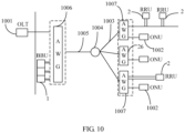
- the passive optical transmission system includes a network side optical line terminal (OLT) 1001 and a user side optical network unit (ONU) 1002.
- OLT network side optical line terminal
- ONU user side optical network unit
- each of three ONUs 1002 is connected to a branch fiber 1003, the three branch fibers 1003 are together connected to an optical splitter 1004, the optical splitter 1004 is connected to a trunk fiber 1005, and the other end of the trunk fiber 1005 is connected to the OLT 1001.
- a first multiplexing and demultiplexing device 1006 may also be disposed at the OLT 1001 side on the passive optical network, and configured to multiplex a signal sent by the OLT 1001 and output the signal to an ONU 1002, and demultiplex a signal sent by the ONU 1002 and output the signal to the OLT 1001.
- a second multiplexing and demultiplexing device 1007 may be disposed at the ONU 1002 side, and configured to multiplex a signal sent by the ONU 1002 and output the signal to the OLT 1001, and demultiplex a signal sent by the OLT 1001 to the ONU 1002.
- RRUs 2 are distributed at the ONU 1002 side, and BBUs 1 are distributed at the OLT 1001 side.
- the RRU 2 and BBU 1 may be respectively connected to the existing second multiplexing and demultiplexing device 1007 and the first multiplexing and demultiplexing device 1006.
- Uplink signals emitted by RRUs 2 are output after being multiplexed by the second multiplexing and demultiplexing device 1007, and are transmitted to the trunk fiber 1005 through corresponding branch fibers 1003; the first multiplexing and demultiplexing device 1006 at the OLT 1001 side demultiplexes the multiplexed signals from the trunk fiber 1005, to colorless optical modules in corresponding BBUs 1.
- downlink signals emitted by BBUs 1 are output, after being multiplexed by the first multiplexing and demultiplexing device 1006 at the OLT 1001 side, to the trunk fiber 1005, and are transmitted to colorless optical modules in corresponding RRUs 2 through the branch fibers 1003 and the second multiplexing and demultiplexing device 1007 at ONU 1002 side.
- BBUs and RRUs can perform signal transmission based on an existing network, so long as no signal interference is caused.
- multiplexing and demultiplexing devices may be added based on the existing fiber resources, where the multiplexing and demultiplexing devices are connected to the existing optical network, so that the BBU 1 and RRU 2 use the existing fiber resources to perform signal transmission.
- service bands used by the BBU 1 and RRU 2 may be different from service bands of an existing passive optical transmission system; when the configured multiplexing and demultiplexing devices disposed in the existing passive optical transmission system are not applicable to bands of the BBU 1 and RRU 2, usually corresponding multiplexing and demultiplexing devices are added based on existing fiber resources (for example, the trunk fiber 1005 and the branch fibers 1003), for signal transmission between the BBU 1 and the RRU 2.
- existing fiber resources for example, the trunk fiber 1005 and the branch fibers 1003
- the base station signal transmission system may be constructed based on an existing passive optical transmission system, and reuse existing fiber resources to transmit signals, thereby implementing an effective combination between this system and the existing network, significantly saving invested material and human resources, and effectively reducing costs.
Landscapes
- Engineering & Computer Science (AREA)
- Computer Networks & Wireless Communication (AREA)
- Signal Processing (AREA)
- Physics & Mathematics (AREA)
- Electromagnetism (AREA)
- Computing Systems (AREA)
- Optical Communication System (AREA)
Claims (1)
- Verteiltes Basisstations-Signalübertragungssystem, umfassend eine Basisbandeinheit (1) und eine Fernfunkeinheit (2) und ferner umfassend:• eine erste Multiplex- und Demultiplexeinheit (3), die zum Multiplexen eines zweiten Downlink-Signals, das von einem ersten farblosen optischen Modul (5) empfangen wird, um dadurch zu einem dritten Downlink-Signal zu gelangen, und Ausgeben des dritten Downlink-Signals an eine zweite Multiplex- und Demultiplexeinheit (4) und Demultiplexen eines dritten Uplink-Signals, das von der zweiten Multiplex- und Demultiplexeinheit (4) empfangen wird, um dadurch zu einem vierten Uplink-Signal zu gelangen, und Ausgeben des vierten Uplink-Signals an das erste farblose optische Modul (5) ausgelegt ist,
wobei die erste Multiplex- und Demultiplexeinheit (3) umfasst:o einen ersten gemeinsamen Anschluss (31), der zum Ausgeben des dritten Downlink-Signals und Empfangen des dritten Uplink-Signals ausgelegt ist, undo einen ersten Zweiganschluss (32), der eins zu eins mit dem ersten farblosen optischen Modul (5) verbunden und zum Senden des durch das erste farblose optische Modul (5) erzeugten zweiten Downlink-Signals an die erste Multiplex- und Demultiplexeinheit (3) und Senden des vierten Uplink-Signals an das erste farblose optische Modul (5) ausgelegt ist;• die zweite Multiplex- und Demultiplexeinheit (4), die zum Multiplexen eines zweiten Uplink-Signals, das von einem zweiten farblosen optischen Modul (6) empfangen wird, um dadurch zum dritten Uplink-Signal zu gelangen, und Ausgeben des dritten Uplink-Signals an die erste Multiplex- und Demultiplexeinheit (3) und Demultiplexen des dritten Downlink-Signals, um dadurch zu einem vierten Downlink-Signal zu gelangen, und Ausgeben des vierten Downlink-Signals an das zweite farblose optische Modul (6) ausgelegt ist, wobei die zweite Multiplex- und Demultiplexeinheit (4) umfasst:o einen zweiten gemeinsamen Anschluss (41), der zum Ausgeben des dritten Uplink-Signals und Empfangen des dritten Downlink-Signals ausgelegt ist,o einen zweiten Zweiganschluss (42), der eins zu eins mit dem zweiten farblosen optischen Modul (6) verbunden und zum Senden des durch das zweite farblose optische Modul (6) erzeugten zweiten Uplink-Signals an die zweite Multiplex- und Demultiplexeinheit (4) und Senden des vierten Downlink-Signals an das zweite farblose optische Modul (6) ausgelegt ist,
wobei der erste gemeinsame Anschluss (31) und der zweite gemeinsame Anschluss (41) durch Verwenden einer einzigen Faser (17) verbunden sind;• das erste farblose optische Modul (5), das zum Empfangen und Parsen des vierten Uplink-Signals und Ausgeben eines fünften Uplink-Signals, das ein elektrisches Signal ist, an die Basisbandeinheit (1) und Erzeugen mittels Modulation eines ersten Downlink-Signals, das ein elektrisches Signal ist, das von einer Basisbandeinheit (1) ausgeben wird, des zweiten Downlink-Signals und Ausgeben des zweiten Downlink-Signals an die erste Multiplex- und Demultiplexeinheit (3) ausgelegt ist;• das zweite farblose optische Modul (6), das zum Empfangen und Parsen des vierten Downlink-Signals und Ausgeben eines fünften Downlink-Signals, das ein elektrisches Signal ist, an die Fernfunkeinheit (2) und Erzeugen mittels Modulation eines ersten Uplink-Signals, das ein elektrisches Signal ist, das von einer Fernfunkeinheit ausgeben wird, des zweiten Uplink-Signals und Ausgeben des zweiten Uplink-Signals an die zweite Multiplex- und Demultiplexeinheit (6) ausgelegt ist;• eine erste Breitspektrum-Lichtquelle (7), die zum Ausgeben eines optischen Breitspektrum-Signals an die erste Multiplex- und Demultiplexeinheit (3) und Bereitstellen von Anregungslicht für das erste farblose optische Modul (5) ausgelegt ist, um das zweite Downlink-Signal zu erzeugen, das ein optisches Signal ist; und• eine zweite Breitspektrum-Lichtquelle (8), die zum Ausgeben eines optischen Breitspektrum-Signals an die zweite Multiplex- und Demultiplexeinheit (4) und Bereitstellen von Anregungslicht für das zweite farblose optische Modul (6) ausgelegt ist, um das zweite Uplink-Signal zu erzeugen, das ein optisches Signal ist; und• wobei ein erster Wellenlängenmultiplexer im ersten farblosen optischen Modul (5) angeordnet ist, ein Ende des ersten Wellenlängenmultiplexers mit dem ersten Zweiganschluss (32) verbunden ist, und das andere Ende mit einem Signalsender und einem Signalempfänger im ersten farblosen optischen Modul (5) verbunden ist;• wobei ein zweiter Wellenlängenmultiplexer im zweiten farblosen optischen Modul (6) angeordnet ist, ein Ende des zweiten Wellenlängenmultiplexers mit dem zweiten Zweiganschluss (42) verbunden ist, und das andere Ende mit einem Signalsender und einem Signalempfänger im zweiten farblosen optischen Modul (6) verbunden ist.
Applications Claiming Priority (2)
| Application Number | Priority Date | Filing Date | Title |
|---|---|---|---|
| CN201210179083.6A CN102710361B (zh) | 2012-06-01 | 2012-06-01 | 一种分布式基站信号传输系统及通信系统 |
| PCT/CN2013/070270 WO2013177957A1 (zh) | 2012-06-01 | 2013-01-09 | 一种分布式基站信号传输系统及通信系统 |
Publications (3)
| Publication Number | Publication Date |
|---|---|
| EP2819325A1 EP2819325A1 (de) | 2014-12-31 |
| EP2819325A4 EP2819325A4 (de) | 2015-04-29 |
| EP2819325B1 true EP2819325B1 (de) | 2023-06-28 |
Family
ID=46902941
Family Applications (1)
| Application Number | Title | Priority Date | Filing Date |
|---|---|---|---|
| EP13798015.7A Active EP2819325B1 (de) | 2012-06-01 | 2013-01-09 | Verteiltes basisstations-signalübertragungssystem und kommunikationssystem |
Country Status (4)
| Country | Link |
|---|---|
| US (1) | US9479254B2 (de) |
| EP (1) | EP2819325B1 (de) |
| CN (1) | CN102710361B (de) |
| WO (1) | WO2013177957A1 (de) |
Families Citing this family (22)
| Publication number | Priority date | Publication date | Assignee | Title |
|---|---|---|---|---|
| CN102710361B (zh) | 2012-06-01 | 2015-09-30 | 华为技术有限公司 | 一种分布式基站信号传输系统及通信系统 |
| EP2770655A1 (de) * | 2013-02-22 | 2014-08-27 | Alcatel Lucent | Verfahren zur Übertragung eines Signals in einem mobilen Netzwerk |
| CN103516429B (zh) * | 2013-09-13 | 2016-03-16 | 北京邮电大学 | 基于本振广播的w波段宽带毫米波全双工接入方法和系统 |
| CN103684867B (zh) * | 2013-12-18 | 2017-03-15 | 烽火通信科技股份有限公司 | 基于固移网接入的管理方法及管理系统 |
| JP6522659B2 (ja) * | 2014-04-29 | 2019-05-29 | 華為技術有限公司Huawei Technologies Co.,Ltd. | 無線通信システムおよび無線ラジオ周波数装置 |
| CN105337666B (zh) * | 2015-10-13 | 2018-10-16 | 安徽理工大学 | Mmc子模块控制器与上层控制器的通信方法及通信系统 |
| US10397355B2 (en) * | 2015-10-30 | 2019-08-27 | American University Of Beirut | System and method for multi-device continuum and seamless sensing platform for context aware analytics |
| CN105472750B (zh) * | 2015-12-08 | 2018-12-14 | 江苏鑫软图无线技术股份有限公司 | 一种基于单天线地铁覆盖场景下的lte频率资源复用方法 |
| CN106304419B (zh) * | 2016-08-15 | 2020-06-12 | 上海交通大学 | 基于多芯光纤的数字光传输的无线前传系统 |
| CN106302291A (zh) * | 2016-08-15 | 2017-01-04 | 上海交通大学 | 基于滤波的正交频分复用技术的前传光网络下行传输系统 |
| CN106304420B (zh) * | 2016-08-15 | 2020-06-12 | 上海交通大学 | 面向5g功率复用的模拟光传输的无线前传系统 |
| CN106358202A (zh) * | 2016-10-13 | 2017-01-25 | 北京邮电大学 | 一种改进的c‑ran网络架构及资源调度方法 |
| CN110226329B (zh) * | 2017-01-27 | 2021-09-21 | 阿帕里奥全球咨询股份有限公司 | 用于将物理显示器的替代图像内容发送到不同观看者的方法和系统 |
| US10009673B1 (en) * | 2017-09-15 | 2018-06-26 | Futurewei Technologies, Inc. | Efficient CPRI transmission |
| CN108092722B (zh) * | 2017-12-14 | 2020-05-12 | 武汉电信器件有限公司 | 一种c-ran多路传输模块的电路及其控制方法 |
| WO2019205173A1 (zh) * | 2018-04-28 | 2019-10-31 | 华为技术有限公司 | 一种无线接入网络、构建方法及通信装置 |
| CN109168277A (zh) * | 2018-10-29 | 2019-01-08 | 深圳市科信通信技术股份有限公司 | 一种c-ran户外机柜 |
| CN112134712B (zh) * | 2019-06-25 | 2021-12-31 | 华为技术有限公司 | 一种信号处理方法以及相关设备 |
| US11289095B2 (en) | 2019-12-30 | 2022-03-29 | Yandex Europe Ag | Method of and system for translating speech to text |
| CN111083808B (zh) * | 2019-12-31 | 2024-02-27 | 京信网络系统股份有限公司 | 基于波分复用的基站系统、数据传输方法和存储介质 |
| CN113872695B (zh) * | 2021-12-06 | 2022-04-01 | 罗森伯格技术有限公司 | 一种分布式天线系统和通信系统 |
| CN215871428U (zh) * | 2021-12-27 | 2022-02-18 | 罗森伯格技术有限公司 | 一种分布式天线系统及通信系统 |
Citations (4)
| Publication number | Priority date | Publication date | Assignee | Title |
|---|---|---|---|---|
| WO2009082113A2 (en) * | 2007-12-21 | 2009-07-02 | Electronics And Telecommunications Research Institute | Wavelength division multiplexing-passive optical network using external seed light source |
| US20110064410A1 (en) * | 2009-09-14 | 2011-03-17 | Nortel Networks Limited | Color free wdm pon based on broadband optical transmitters |
| EP2398166A2 (de) * | 2009-02-13 | 2011-12-21 | Korea Advanced Institute of Science and Technology | Geräuscharmer optischer signalsender mit geräuscharmer lichtquelle mit mehreren wellenlängen, rundfunksignalsender mit der geräuscharmen lichtquelle mit mehreren wellenlängen und optisches netzwerk damit |
| EP2429100A2 (de) * | 2009-04-30 | 2012-03-14 | Korea Advanced Institute of Science and Technology | Lichtquelle für optische kommunikation mit wellenlängenteilungsmultiplexing zur hochgeschwindigkeitsübertragung eines optischen signals mithilfe einer unpolarisierten lichtquelle sowie passives optisches netzwerk mit wellenlängenteilungsmultiplexing |
Family Cites Families (23)
| Publication number | Priority date | Publication date | Assignee | Title |
|---|---|---|---|---|
| US20030027597A1 (en) * | 2001-07-31 | 2003-02-06 | Lagrotta James T. | Use of over-the-air optical link within a geographically distributed base station |
| CN101043287B (zh) * | 2006-03-24 | 2012-02-22 | 华为技术有限公司 | 波分复用的无源光网络的传输方法和系统 |
| KR100819034B1 (ko) | 2006-05-11 | 2008-04-03 | 한국전자통신연구원 | 반사형 반도체 광증폭기 기반 수동형 광가입자망 |
| US7965947B2 (en) | 2006-12-05 | 2011-06-21 | Nec Laboratories America, Inc. | Wavelength division multiplexing passive optical network architecture with source-free optical network units |
| WO2009123571A1 (en) | 2008-03-31 | 2009-10-08 | Agency For Science, Technology And Research | A wdm-pon architecture based on externally seeded optical source |
| IE20090412A1 (en) | 2008-05-27 | 2009-12-09 | Univ College Cork Nat Univ Ie | A reflective optical transmitter |
| WO2009151355A1 (en) * | 2008-06-10 | 2009-12-17 | Telefonaktiebolaget Lm Ericsson (Publ) | Method and arrangement for performing handover in a wireless communication system |
| KR100969741B1 (ko) * | 2008-07-11 | 2010-07-13 | 엘지노텔 주식회사 | 환형 혼성 성형망을 제공하기 위한 광통신 시스템 |
| KR100987793B1 (ko) | 2008-10-10 | 2010-10-13 | 한국전자통신연구원 | 반사형 반도체 광 증폭기 및 이를 이용하는 광신호 처리방법 |
| US20100111533A1 (en) | 2008-11-06 | 2010-05-06 | Nortel Networks Limited | Wdm pon system |
| CN101841748B (zh) * | 2009-03-17 | 2013-06-12 | 中国移动通信集团公司 | 信号传输系统以及相关装置 |
| ES2843024T3 (es) * | 2009-07-27 | 2021-07-15 | Huawei Tech Co Ltd | Método y aparato de tratamiento de transmisión de señal y estación de base distribuida |
| US8238750B2 (en) * | 2009-08-04 | 2012-08-07 | Cisco Technology, Inc. | Split/smart channel allocated WDM-PON architecture |
| US8417118B2 (en) * | 2009-08-14 | 2013-04-09 | Futurewei Technologies, Inc. | Colorless dense wavelength division multiplexing transmitters |
| CN102065343B (zh) * | 2009-11-16 | 2013-10-02 | 华为技术有限公司 | 波长选择方法、装置及系统 |
| CN102082610B (zh) * | 2009-12-01 | 2014-07-30 | 华为技术有限公司 | 自注入锁定光源、光源自注入锁定方法和系统 |
| US20120269509A1 (en) * | 2011-04-21 | 2012-10-25 | Antonius Petrus Hultermans | Remote Electronic Component, Such As Remote Radio Head, For A Wireless Communication System, Remote Electronic Component Array And External Distributor Unit |
| BR112014003030B1 (pt) * | 2011-08-11 | 2021-09-08 | Apple Inc | Método para comutar de um download de mbms para um fornecimento com base em http de conteúdo formatado dash, método para comutar de um fornecimento com base em http de conteúdo formatado dash para um download de mbms e dispositivo móvel |
| US20140241315A1 (en) * | 2011-09-30 | 2014-08-28 | Huaning Niu | Radio access network (ran) for peer-to-peer (p2p) communication |
| EP2761972A4 (de) * | 2011-10-01 | 2015-08-12 | Intel Corp | Eintfernte funkeinheit (rru) und basisbandeinheit (bbu) |
| CN102412905B (zh) * | 2011-11-10 | 2015-04-29 | 北京邮电大学 | 波分时分混合无源光网络系统 |
| US9287987B2 (en) * | 2011-12-01 | 2016-03-15 | Futurewei Technologies, Inc. | Self-seeded colorless burst-mode transmitter using reflective semiconductor optical amplifier and injection locked Fabry-Perot laser |
| CN102710361B (zh) * | 2012-06-01 | 2015-09-30 | 华为技术有限公司 | 一种分布式基站信号传输系统及通信系统 |
-
2012
- 2012-06-01 CN CN201210179083.6A patent/CN102710361B/zh active Active
-
2013
- 2013-01-09 WO PCT/CN2013/070270 patent/WO2013177957A1/zh not_active Ceased
- 2013-01-09 EP EP13798015.7A patent/EP2819325B1/de active Active
-
2014
- 2014-09-25 US US14/496,777 patent/US9479254B2/en not_active Expired - Fee Related
Patent Citations (4)
| Publication number | Priority date | Publication date | Assignee | Title |
|---|---|---|---|---|
| WO2009082113A2 (en) * | 2007-12-21 | 2009-07-02 | Electronics And Telecommunications Research Institute | Wavelength division multiplexing-passive optical network using external seed light source |
| EP2398166A2 (de) * | 2009-02-13 | 2011-12-21 | Korea Advanced Institute of Science and Technology | Geräuscharmer optischer signalsender mit geräuscharmer lichtquelle mit mehreren wellenlängen, rundfunksignalsender mit der geräuscharmen lichtquelle mit mehreren wellenlängen und optisches netzwerk damit |
| EP2429100A2 (de) * | 2009-04-30 | 2012-03-14 | Korea Advanced Institute of Science and Technology | Lichtquelle für optische kommunikation mit wellenlängenteilungsmultiplexing zur hochgeschwindigkeitsübertragung eines optischen signals mithilfe einer unpolarisierten lichtquelle sowie passives optisches netzwerk mit wellenlängenteilungsmultiplexing |
| US20110064410A1 (en) * | 2009-09-14 | 2011-03-17 | Nortel Networks Limited | Color free wdm pon based on broadband optical transmitters |
Non-Patent Citations (2)
| Title |
|---|
| AHN J-G ET AL: "Fiber-to-the-Home Services Based on Wavelength-Division-Multiplexing Passive Optical Network", JOURNAL OF LIGHTWAVE TECHNOLOGY, IEEE, USA, vol. 22, no. 11, 1 November 2004 (2004-11-01), pages 2582 - 2591, XP011121526, ISSN: 0733-8724, DOI: 10.1109/JLT.2004.834504 * |
| KI-MAN CHOI ET AL: "An Efficient Evolution Method From TDM-PON to Next-Generation PON", IEEE PHOTONICS TECHNOLOGY LETTERS, IEEE SERVICE CENTER, PISCATAWAY, NJ, US, vol. 19, no. 9, 1 May 2007 (2007-05-01), pages 647 - 649, XP011184438, ISSN: 1041-1135, DOI: 10.1109/LPT.2007.894958 * |
Also Published As
| Publication number | Publication date |
|---|---|
| EP2819325A1 (de) | 2014-12-31 |
| CN102710361B (zh) | 2015-09-30 |
| EP2819325A4 (de) | 2015-04-29 |
| CN102710361A (zh) | 2012-10-03 |
| WO2013177957A1 (zh) | 2013-12-05 |
| US9479254B2 (en) | 2016-10-25 |
| US20150010024A1 (en) | 2015-01-08 |
Similar Documents
| Publication | Publication Date | Title |
|---|---|---|
| EP2819325B1 (de) | Verteiltes basisstations-signalübertragungssystem und kommunikationssystem | |
| KR100875922B1 (ko) | Wdm 수동형 광가입자망에서의 파장 무의존 광원을이용한 하향 광송신 장치 및 그 방법과, 그를 이용한광선로 종단 시스템 | |
| RU2562808C2 (ru) | Устройство оптического приемопередатчика и система пассивных оптических сетей с мультиплексированием с разделением по длине волны | |
| US9124368B2 (en) | Transceiver for use in fibre network | |
| Grobe et al. | PON in adolescence: from TDMA to WDM-PON | |
| US8554079B2 (en) | Wavelength division and time division multiplex mixing passive optical network system, terminal and signal transmission method | |
| KR101410158B1 (ko) | 신호 전송 시스템, 방법 및 관련 장치 | |
| EP3169010B1 (de) | Twdm-passivnetzwerk mit erweiterter reichweite und kapazität | |
| US7706688B2 (en) | Wavelength reconfigurable optical network | |
| KR20100092853A (ko) | 저잡음 다파장 광원을 구비한 저잡음 광신호의 전송 장치, 저잡음 다파장 광원을 이용한 방송 신호 전송 장치, 및 이를 구비한 광가입자망 | |
| CN101827288A (zh) | 一种基于波长可变的混合光接入系统 | |
| US20100021164A1 (en) | Wdm pon rf/video broadcast overlay | |
| CN102075819A (zh) | 一种波分时分混合复用的无源光网络系统 | |
| CN101835070B (zh) | 波分复用无源光网络实现波长重用和广播功能的系统和方法 | |
| CN104486028B (zh) | 波分复用光接入网低成本局域网业务传输的系统和方法 | |
| CN101527610B (zh) | 具有1:n波长备份功能的波分复用无源光网络系统 | |
| CA2593891C (en) | Wavelength reconfigurable optical network | |
| KR100932899B1 (ko) | Wdm-pon의 광선로 종단 시스템에서 파장 무의존 하향광송신 장치 및 방법 | |
| WO2026078825A1 (ja) | 通信システム、通信装置、及び、通信方法 | |
| Urban et al. | Simulation results of dynamically reconfigurable broadband photonic access networks (BB Photonics) | |
| CN102075281A (zh) | 基站信号的传输方法、中心基站、远程基站及系统 | |
| KR20080069068A (ko) | 파장분할다중 방식의 수동형 광가입자망 시스템 |
Legal Events
| Date | Code | Title | Description |
|---|---|---|---|
| PUAI | Public reference made under article 153(3) epc to a published international application that has entered the european phase |
Free format text: ORIGINAL CODE: 0009012 |
|
| 17P | Request for examination filed |
Effective date: 20140924 |
|
| AK | Designated contracting states |
Kind code of ref document: A1 Designated state(s): AL AT BE BG CH CY CZ DE DK EE ES FI FR GB GR HR HU IE IS IT LI LT LU LV MC MK MT NL NO PL PT RO RS SE SI SK SM TR |
|
| AX | Request for extension of the european patent |
Extension state: BA ME |
|
| RA4 | Supplementary search report drawn up and despatched (corrected) |
Effective date: 20150401 |
|
| RIC1 | Information provided on ipc code assigned before grant |
Ipc: H04J 14/02 20060101AFI20150326BHEP Ipc: H04B 10/27 20130101ALI20150326BHEP Ipc: H04B 10/2575 20130101ALI20150326BHEP Ipc: H04B 10/25 20130101ALI20150326BHEP |
|
| DAX | Request for extension of the european patent (deleted) | ||
| STAA | Information on the status of an ep patent application or granted ep patent |
Free format text: STATUS: EXAMINATION IS IN PROGRESS |
|
| 17Q | First examination report despatched |
Effective date: 20190614 |
|
| GRAP | Despatch of communication of intention to grant a patent |
Free format text: ORIGINAL CODE: EPIDOSNIGR1 |
|
| STAA | Information on the status of an ep patent application or granted ep patent |
Free format text: STATUS: GRANT OF PATENT IS INTENDED |
|
| INTG | Intention to grant announced |
Effective date: 20230111 |
|
| GRAS | Grant fee paid |
Free format text: ORIGINAL CODE: EPIDOSNIGR3 |
|
| GRAA | (expected) grant |
Free format text: ORIGINAL CODE: 0009210 |
|
| STAA | Information on the status of an ep patent application or granted ep patent |
Free format text: STATUS: THE PATENT HAS BEEN GRANTED |
|
| AK | Designated contracting states |
Kind code of ref document: B1 Designated state(s): AL AT BE BG CH CY CZ DE DK EE ES FI FR GB GR HR HU IE IS IT LI LT LU LV MC MK MT NL NO PL PT RO RS SE SI SK SM TR |
|
| REG | Reference to a national code |
Ref country code: CH Ref legal event code: EP |
|
| REG | Reference to a national code |
Ref country code: AT Ref legal event code: REF Ref document number: 1583668 Country of ref document: AT Kind code of ref document: T Effective date: 20230715 |
|
| REG | Reference to a national code |
Ref country code: IE Ref legal event code: FG4D |
|
| REG | Reference to a national code |
Ref country code: DE Ref legal event code: R096 Ref document number: 602013084130 Country of ref document: DE |
|
| P01 | Opt-out of the competence of the unified patent court (upc) registered |
Effective date: 20230727 |
|
| REG | Reference to a national code |
Ref country code: LT Ref legal event code: MG9D |
|
| PG25 | Lapsed in a contracting state [announced via postgrant information from national office to epo] |
Ref country code: SE Free format text: LAPSE BECAUSE OF FAILURE TO SUBMIT A TRANSLATION OF THE DESCRIPTION OR TO PAY THE FEE WITHIN THE PRESCRIBED TIME-LIMIT Effective date: 20230628 Ref country code: NO Free format text: LAPSE BECAUSE OF FAILURE TO SUBMIT A TRANSLATION OF THE DESCRIPTION OR TO PAY THE FEE WITHIN THE PRESCRIBED TIME-LIMIT Effective date: 20230928 |
|
| REG | Reference to a national code |
Ref country code: NL Ref legal event code: MP Effective date: 20230628 |
|
| REG | Reference to a national code |
Ref country code: AT Ref legal event code: MK05 Ref document number: 1583668 Country of ref document: AT Kind code of ref document: T Effective date: 20230628 |
|
| PG25 | Lapsed in a contracting state [announced via postgrant information from national office to epo] |
Ref country code: RS Free format text: LAPSE BECAUSE OF FAILURE TO SUBMIT A TRANSLATION OF THE DESCRIPTION OR TO PAY THE FEE WITHIN THE PRESCRIBED TIME-LIMIT Effective date: 20230628 Ref country code: NL Free format text: LAPSE BECAUSE OF FAILURE TO SUBMIT A TRANSLATION OF THE DESCRIPTION OR TO PAY THE FEE WITHIN THE PRESCRIBED TIME-LIMIT Effective date: 20230628 Ref country code: LV Free format text: LAPSE BECAUSE OF FAILURE TO SUBMIT A TRANSLATION OF THE DESCRIPTION OR TO PAY THE FEE WITHIN THE PRESCRIBED TIME-LIMIT Effective date: 20230628 Ref country code: LT Free format text: LAPSE BECAUSE OF FAILURE TO SUBMIT A TRANSLATION OF THE DESCRIPTION OR TO PAY THE FEE WITHIN THE PRESCRIBED TIME-LIMIT Effective date: 20230628 Ref country code: HR Free format text: LAPSE BECAUSE OF FAILURE TO SUBMIT A TRANSLATION OF THE DESCRIPTION OR TO PAY THE FEE WITHIN THE PRESCRIBED TIME-LIMIT Effective date: 20230628 Ref country code: GR Free format text: LAPSE BECAUSE OF FAILURE TO SUBMIT A TRANSLATION OF THE DESCRIPTION OR TO PAY THE FEE WITHIN THE PRESCRIBED TIME-LIMIT Effective date: 20230929 |
|
| PG25 | Lapsed in a contracting state [announced via postgrant information from national office to epo] |
Ref country code: FI Free format text: LAPSE BECAUSE OF FAILURE TO SUBMIT A TRANSLATION OF THE DESCRIPTION OR TO PAY THE FEE WITHIN THE PRESCRIBED TIME-LIMIT Effective date: 20230628 |
|
| PG25 | Lapsed in a contracting state [announced via postgrant information from national office to epo] |
Ref country code: SK Free format text: LAPSE BECAUSE OF FAILURE TO SUBMIT A TRANSLATION OF THE DESCRIPTION OR TO PAY THE FEE WITHIN THE PRESCRIBED TIME-LIMIT Effective date: 20230628 |
|
| PG25 | Lapsed in a contracting state [announced via postgrant information from national office to epo] |
Ref country code: ES Free format text: LAPSE BECAUSE OF FAILURE TO SUBMIT A TRANSLATION OF THE DESCRIPTION OR TO PAY THE FEE WITHIN THE PRESCRIBED TIME-LIMIT Effective date: 20230628 |
|
| PG25 | Lapsed in a contracting state [announced via postgrant information from national office to epo] |
Ref country code: IS Free format text: LAPSE BECAUSE OF FAILURE TO SUBMIT A TRANSLATION OF THE DESCRIPTION OR TO PAY THE FEE WITHIN THE PRESCRIBED TIME-LIMIT Effective date: 20231028 |
|
| PG25 | Lapsed in a contracting state [announced via postgrant information from national office to epo] |
Ref country code: SM Free format text: LAPSE BECAUSE OF FAILURE TO SUBMIT A TRANSLATION OF THE DESCRIPTION OR TO PAY THE FEE WITHIN THE PRESCRIBED TIME-LIMIT Effective date: 20230628 Ref country code: SK Free format text: LAPSE BECAUSE OF FAILURE TO SUBMIT A TRANSLATION OF THE DESCRIPTION OR TO PAY THE FEE WITHIN THE PRESCRIBED TIME-LIMIT Effective date: 20230628 Ref country code: RO Free format text: LAPSE BECAUSE OF FAILURE TO SUBMIT A TRANSLATION OF THE DESCRIPTION OR TO PAY THE FEE WITHIN THE PRESCRIBED TIME-LIMIT Effective date: 20230628 Ref country code: PT Free format text: LAPSE BECAUSE OF FAILURE TO SUBMIT A TRANSLATION OF THE DESCRIPTION OR TO PAY THE FEE WITHIN THE PRESCRIBED TIME-LIMIT Effective date: 20231030 Ref country code: IS Free format text: LAPSE BECAUSE OF FAILURE TO SUBMIT A TRANSLATION OF THE DESCRIPTION OR TO PAY THE FEE WITHIN THE PRESCRIBED TIME-LIMIT Effective date: 20231028 Ref country code: ES Free format text: LAPSE BECAUSE OF FAILURE TO SUBMIT A TRANSLATION OF THE DESCRIPTION OR TO PAY THE FEE WITHIN THE PRESCRIBED TIME-LIMIT Effective date: 20230628 Ref country code: EE Free format text: LAPSE BECAUSE OF FAILURE TO SUBMIT A TRANSLATION OF THE DESCRIPTION OR TO PAY THE FEE WITHIN THE PRESCRIBED TIME-LIMIT Effective date: 20230628 Ref country code: CZ Free format text: LAPSE BECAUSE OF FAILURE TO SUBMIT A TRANSLATION OF THE DESCRIPTION OR TO PAY THE FEE WITHIN THE PRESCRIBED TIME-LIMIT Effective date: 20230628 Ref country code: AT Free format text: LAPSE BECAUSE OF FAILURE TO SUBMIT A TRANSLATION OF THE DESCRIPTION OR TO PAY THE FEE WITHIN THE PRESCRIBED TIME-LIMIT Effective date: 20230628 |
|
| PG25 | Lapsed in a contracting state [announced via postgrant information from national office to epo] |
Ref country code: PL Free format text: LAPSE BECAUSE OF FAILURE TO SUBMIT A TRANSLATION OF THE DESCRIPTION OR TO PAY THE FEE WITHIN THE PRESCRIBED TIME-LIMIT Effective date: 20230628 |
|
| REG | Reference to a national code |
Ref country code: DE Ref legal event code: R097 Ref document number: 602013084130 Country of ref document: DE |
|
| PG25 | Lapsed in a contracting state [announced via postgrant information from national office to epo] |
Ref country code: DK Free format text: LAPSE BECAUSE OF FAILURE TO SUBMIT A TRANSLATION OF THE DESCRIPTION OR TO PAY THE FEE WITHIN THE PRESCRIBED TIME-LIMIT Effective date: 20230628 |
|
| PLBE | No opposition filed within time limit |
Free format text: ORIGINAL CODE: 0009261 |
|
| STAA | Information on the status of an ep patent application or granted ep patent |
Free format text: STATUS: NO OPPOSITION FILED WITHIN TIME LIMIT |
|
| PG25 | Lapsed in a contracting state [announced via postgrant information from national office to epo] |
Ref country code: IT Free format text: LAPSE BECAUSE OF FAILURE TO SUBMIT A TRANSLATION OF THE DESCRIPTION OR TO PAY THE FEE WITHIN THE PRESCRIBED TIME-LIMIT Effective date: 20230628 |
|
| 26N | No opposition filed |
Effective date: 20240402 |
|
| PG25 | Lapsed in a contracting state [announced via postgrant information from national office to epo] |
Ref country code: SI Free format text: LAPSE BECAUSE OF FAILURE TO SUBMIT A TRANSLATION OF THE DESCRIPTION OR TO PAY THE FEE WITHIN THE PRESCRIBED TIME-LIMIT Effective date: 20230628 |
|
| PG25 | Lapsed in a contracting state [announced via postgrant information from national office to epo] |
Ref country code: MC Free format text: LAPSE BECAUSE OF FAILURE TO SUBMIT A TRANSLATION OF THE DESCRIPTION OR TO PAY THE FEE WITHIN THE PRESCRIBED TIME-LIMIT Effective date: 20230628 |
|
| PG25 | Lapsed in a contracting state [announced via postgrant information from national office to epo] |
Ref country code: MC Free format text: LAPSE BECAUSE OF FAILURE TO SUBMIT A TRANSLATION OF THE DESCRIPTION OR TO PAY THE FEE WITHIN THE PRESCRIBED TIME-LIMIT Effective date: 20230628 |
|
| REG | Reference to a national code |
Ref country code: CH Ref legal event code: PL |
|
| PG25 | Lapsed in a contracting state [announced via postgrant information from national office to epo] |
Ref country code: LU Free format text: LAPSE BECAUSE OF NON-PAYMENT OF DUE FEES Effective date: 20240109 |
|
| GBPC | Gb: european patent ceased through non-payment of renewal fee |
Effective date: 20240109 |
|
| PG25 | Lapsed in a contracting state [announced via postgrant information from national office to epo] |
Ref country code: LU Free format text: LAPSE BECAUSE OF NON-PAYMENT OF DUE FEES Effective date: 20240109 |
|
| PG25 | Lapsed in a contracting state [announced via postgrant information from national office to epo] |
Ref country code: GB Free format text: LAPSE BECAUSE OF NON-PAYMENT OF DUE FEES Effective date: 20240109 |
|
| PG25 | Lapsed in a contracting state [announced via postgrant information from national office to epo] |
Ref country code: BE Free format text: LAPSE BECAUSE OF NON-PAYMENT OF DUE FEES Effective date: 20240131 |
|
| PG25 | Lapsed in a contracting state [announced via postgrant information from national office to epo] |
Ref country code: FR Free format text: LAPSE BECAUSE OF NON-PAYMENT OF DUE FEES Effective date: 20240131 |
|
| PG25 | Lapsed in a contracting state [announced via postgrant information from national office to epo] |
Ref country code: CH Free format text: LAPSE BECAUSE OF NON-PAYMENT OF DUE FEES Effective date: 20240131 |
|
| PG25 | Lapsed in a contracting state [announced via postgrant information from national office to epo] |
Ref country code: GB Free format text: LAPSE BECAUSE OF NON-PAYMENT OF DUE FEES Effective date: 20240109 Ref country code: FR Free format text: LAPSE BECAUSE OF NON-PAYMENT OF DUE FEES Effective date: 20240131 Ref country code: CH Free format text: LAPSE BECAUSE OF NON-PAYMENT OF DUE FEES Effective date: 20240131 Ref country code: BE Free format text: LAPSE BECAUSE OF NON-PAYMENT OF DUE FEES Effective date: 20240131 |
|
| REG | Reference to a national code |
Ref country code: BE Ref legal event code: MM Effective date: 20240131 |
|
| PG25 | Lapsed in a contracting state [announced via postgrant information from national office to epo] |
Ref country code: BG Free format text: LAPSE BECAUSE OF FAILURE TO SUBMIT A TRANSLATION OF THE DESCRIPTION OR TO PAY THE FEE WITHIN THE PRESCRIBED TIME-LIMIT Effective date: 20230628 |
|
| PG25 | Lapsed in a contracting state [announced via postgrant information from national office to epo] |
Ref country code: BG Free format text: LAPSE BECAUSE OF FAILURE TO SUBMIT A TRANSLATION OF THE DESCRIPTION OR TO PAY THE FEE WITHIN THE PRESCRIBED TIME-LIMIT Effective date: 20230628 |
|
| PG25 | Lapsed in a contracting state [announced via postgrant information from national office to epo] |
Ref country code: IE Free format text: LAPSE BECAUSE OF NON-PAYMENT OF DUE FEES Effective date: 20240109 |
|
| PG25 | Lapsed in a contracting state [announced via postgrant information from national office to epo] |
Ref country code: IE Free format text: LAPSE BECAUSE OF NON-PAYMENT OF DUE FEES Effective date: 20240109 |
|
| PGFP | Annual fee paid to national office [announced via postgrant information from national office to epo] |
Ref country code: DE Payment date: 20241203 Year of fee payment: 13 |
|
| PG25 | Lapsed in a contracting state [announced via postgrant information from national office to epo] |
Ref country code: CY Free format text: LAPSE BECAUSE OF FAILURE TO SUBMIT A TRANSLATION OF THE DESCRIPTION OR TO PAY THE FEE WITHIN THE PRESCRIBED TIME-LIMIT; INVALID AB INITIO Effective date: 20130109 |
|
| PG25 | Lapsed in a contracting state [announced via postgrant information from national office to epo] |
Ref country code: HU Free format text: LAPSE BECAUSE OF FAILURE TO SUBMIT A TRANSLATION OF THE DESCRIPTION OR TO PAY THE FEE WITHIN THE PRESCRIBED TIME-LIMIT; INVALID AB INITIO Effective date: 20130109 |
|
| PG25 | Lapsed in a contracting state [announced via postgrant information from national office to epo] |
Ref country code: TR Free format text: LAPSE BECAUSE OF FAILURE TO SUBMIT A TRANSLATION OF THE DESCRIPTION OR TO PAY THE FEE WITHIN THE PRESCRIBED TIME-LIMIT Effective date: 20230628 |