EP2819940B1 - Fabrication de papier - Google Patents
Fabrication de papier Download PDFInfo
- Publication number
- EP2819940B1 EP2819940B1 EP13754509.1A EP13754509A EP2819940B1 EP 2819940 B1 EP2819940 B1 EP 2819940B1 EP 13754509 A EP13754509 A EP 13754509A EP 2819940 B1 EP2819940 B1 EP 2819940B1
- Authority
- EP
- European Patent Office
- Prior art keywords
- trim
- duct
- web
- air jet
- inlet
- Prior art date
- Legal status (The legal status is an assumption and is not a legal conclusion. Google has not performed a legal analysis and makes no representation as to the accuracy of the status listed.)
- Active
Links
Images


Classifications
-
- D—TEXTILES; PAPER
- D21—PAPER-MAKING; PRODUCTION OF CELLULOSE
- D21F—PAPER-MAKING MACHINES; METHODS OF PRODUCING PAPER THEREON
- D21F7/00—Other details of machines for making continuous webs of paper
- D21F7/006—Cutting the edges of the paper-web
Definitions
- the present application relates to paper manufacturing, and in particular to equipment and methods for handling trim.
- Paper making machinery produces a web of paper. It is known to trim side edges of the web. It is known in the art to cut the trim using a blade, such as a rotary blade, or using a water jet. An overview of trim handling systems is described in the article, " Trim Handling Systems" presented at the TAPPI Papermaking Conference, Atlanta, Georgia, 1999 .
- trim conveying systems may be divided into five categories as follows:
- the trim material is removed from the web using a duct or chute and a source of negative pressure to draw the trim into the duct or chute.
- the trim material is typically guided into the pulper of the paper making machine and immediately returned into producing paper.
- Some paper making machines have web speeds well above 60km/h, and in fact as high as 100km/h to 140km/h. At such speeds, a number of problems arise in edge trimming, for example, the stability of the web due to air turbulence, as is described in commonly-assigned PCT publication WO 2011/121390 .
- the separating of the trim can be done on slow webs by hand, however, this is not the case for high speed webs. It is known in the art to use a water jet system to separate the trim when the trimming tool engages the web. This typically involves using a number of small water jets placed across the trim width that are pulsed to cause a break in the trim (and not in the web). In the case of a water jet trim tool, the jet is positioned over the web, and the jet is turned on to begin the trim cutting. Very shortly thereafter, the separation of the trim from itself ensues.
- EP 1445 376 A1 to Voith Paper Patent GmbH discloses a device for cutting an edge of a fibrous layer in a papermaking machine, wherein the trimming station uses means of air and/or water to separate an edge portion of the fibrous layer.
- a means of negative pressure is provided in the tube of the discharge device that receives the severed edge of the fibrous layer, to remove this severed edge and for example transfer it to a recycling device.
- WO 2009/119194 A1 to Mitsubish Heavy Industries, Ltd. discloses a trimming method and device of a machine manufacturing corrugated board sheets. Trim pieces are cut from the web by a rotary shear and sucked into a suction opening of a trim shooter, the latter having a blower that sucks the trim to propel it along the pipeline and on to a wate processing unit, for example.
- JP H07 237185A to Hitachi Chemical Co. Ltd. discloses a sheet cutting device that efficiently collects trimmings generated when the trimmings of a continuous sheet are cut.
- a suction port is arranged underneath the moving sheet, this suction portion generating negative pressure to suck the cut trimmings downwardly into and through a chute.
- Applicants have used in a trim handling duct an air amplifier jet, at the outlet of the duct in an upper part of the repulper, to create a negative pressure in the duct to draw trim along the duct.
- the same system used additionally a pair of conical air jets to push trim into the inlet of the trim handling duct.
- a wide air jet covering the width of the trim namely a jet from an air knife or air wedge, can propel trim into a trim handling duct over distances of about 2m to 3m without the use of a vacuum source in the duct.
- the trim is efficiently carried and/or propelled by the air jet and pushed out the outlet of the duct into the pulper.
- trim can be propelled farther along a duct, or heavier trim can be propelled along a duct for the same distance, using additional air knives within the trim handling duct. This propulsion of trim within the duct can be done without use of a source of negative pressure in the duct.
- the air jet is used both for separating the trim and for driving the trim into the duct or chute, it has been found that the air jet that is powerful enough to sever the trim is sufficiently strong to create a driving airflow that will guide the trim into a duct or along a chute over a distance sufficient for effective removal of the trim from the immediate area of web.
- the airflow created by the trim separating air jet can carry the trim at sufficient speed between one to five meters.
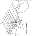
- Figure 1 shows a three-dimensional sketch of a portion of a paper production installation according to PCT publication WO 2011/121390 .
- a stabilizer 40 has attached thereto an apparatus for cutting a material web, which apparatus has an extension device 44 having a recess 45, and has a cutting device 20 (e.g. a water jet) and a cutting table 23 that has an optional inclined surface 24.
- the material web 10 runs through an edge trimming apparatus to a succeeding reel.
- the apparatus for cutting a material web 10 consists of an air guide box or stabilizer 40 having a cutting device 20, which has an extension device 44.
- a recess 45 is provided in the extension device 44.
- the structural unit 30, via a carrier beam 31 mounted transversely over the material web 10, is arranged so as to be movable transversely in relation to the material web 10.
- the material web 10 is severed by means of a high-pressure water jet 22.
- the resultant edge strip 11 is removed via the shaft 25 provided on the cutting table 23.
- the edge strip 11 in this case is already sliding into the shaft 25 because of the forward motion of the material web 10.
- the edge strip 11 is sucked away out of the plane of the material web and into the shaft 25 by a suction device attached to the shaft 25.
- the inclined surface 24 provided on the cutting table 23 effects additional stabilization of the material web 10 over the cutting table.
- the structural unit 30, consisting of the cutting device 20 and the cutting table 23, and of the elements attached thereto, is moved laterally out of the recess 45 by means of the carrier beam 31. This structural unit 30 is then moved back into the transport path of the material web 10, in order to support the newly incoming and extending web.
- Linear air nozzle and “linear air jet” are used to mean an air nozzle and an air jet air flow or stream respectively, such as an air knife or air wedge nozzle that produces a wide and thin stream at sufficient velocity to propel the paper trim.
- An air knife is a tool used typically for cleaning surfaces of objects.
- the high velocity stream can be formed by arranging a number of small nozzles in a row or by having a nozzle orifice that is a slit.
- Air wedge nozzles have a row of small nozzles. The jets from the small nozzles blend together into the stream.
- High velocity air jets also induce ambient air around the nozzle to flow with the nozzle jet, an effect known as air amplification.
- the flow rate induced by an air amplifier nozzle can be many times the flow rate fed to the high velocity nozzle.
- An air wedge nozzle can be shaped to help air amplification flow. In the case of a slit nozzle, the slit can be uniform or provide greater airflow at the side ends of the stream for better stream stability.
- the water jet cuts the edge trim, and the trim is pushed into the shaft or duct using a linear air jet 14.
- Applicants have used the Hurricane(TM) wedge 38150 from AiRTX of Cincinnati, Ohio, USA, and found it to work satisfactorily on tissue trim with an air supply at 40 psi (about 270kPa) without using any suction in the duct.
- the airflow of the nozzle in this case is about 1470 litres per minute.
- An AiRTX 80000 series air knife nozzle 16 was also arranged on both sides of the duct 25 used at 50 psi (about 325kPa) and a flow of about 425 litres per minute to drive the trim within the duct.
- the wedge has a large number of small nozzle orifices and is shaped to create a strong inverted wedge-shaped air curtain that travels with good speed and distance.
- the air knife uses higher pressure and less air flow, however, its strong air curtain travels a shorter distance.
- the combined air flow of about 1900 litres per minute was found to be less than what is required to reliably handle the trim discharge using suction flow or even using a plurality of air nozzles with a shorter nozzle dimension in the transverse direction with respect to the web transport direction.
- an arrangement of two super air nozzles from Exair at 80 psi (550kPa) and 14 CFM (400 litres per minute) each used to divert the trim into the duct, followed at the duct outlet by an AiRTX model 15000 air amplifier at 80 psi (550kPa) and 60 CFM (1700 litres per minute) has been used by Applicant and shown to perform satisfactorily for trim handling from the trim station to a repulper immediately below the trim station.
- the three nozzles consume a total of 88CFM (2500 litres per minute), namely about 30% more compressed air flow.
- the air amplifier used induces suction in the duct, creating greater air flow through the duct into the repulper.
- the use of the air knife jet, as illustrated in Figure 2 is on both sides of the trim. This provides active air flow on both sides of the trim within the duct to transport the trim to its destination, for example, a pulper.
- the duct can be substantially of rectangular cross-section as illustrated in Figure 2 .
- the duct shape while possibly initially rectangular, can transition to a circular cross-section duct.
- the cross-section of the duct can be determined in accordance with an expected trim and air flow rate. For example, reducing a cross-sectional area will increase a flow speed, while this can result in a greater chance for blockage as the cross-sectional area of the duct decreases. Likewise, a decrease in flow speed of trim can lead to a pile up of trim and blockage of the duct.
- the design of the duct and the provision of the air jets are selected to provide efficient carriage of the trim without blockage.
- the air wedge is mounted within 3 cm to 15 cm from the cutting water jet.
- the air wedge can have sufficient force to break the trim held under tension, or the air wedge can cause a break in the trim by forcing the trim against the downstream edge of the duct opening.
- a water spray can be applied to the trim to weaken it prior to causing the break and separation.
- the pulper is located below the cutting station near the winder.
- the duct can be straight or it can involve one or more bends before reaching the pulper.
- the trim cutting water jet 12 is shown with a bowl-shaped air flow stabilizer.
- the web support surface forms part of the remaining web support surface of the paper making machine.
- the air wedge 14 is positioned above the inlet to the trim discharge duct 25 having a break edge 26 on its downstream side.
- the trim cut by the jet 12 is initially separated from the web by turning on the wedge nozzle 14 with the result that the trim is pushed into the duct inlet against the edge 26.
- the trim is thereby torn and the air stream from wedge 14 propels the trim into and along duct 25.
- transport of the trim in the duct takes place without using a source of negative pressure.
- a linear jet has been shown to be particularly efficient in propelling trim into the duct without needing a source of suction or negative pressure.
Landscapes
- Advancing Webs (AREA)
- Paper (AREA)
Claims (10)
- Procédé de production de papier dans lequel une bande de papier est préparée et acheminée vers une bobine finale avec au moins un bord latéral de la bande étant rogné pour produire une rognure (11) acheminée par un conduit (25) pour recyclage, le procédé comprenant:la fourniture d'une buse (14) par-dessus la rognure et orientée transversalement par rapport à la rognure (11), positionnée par-dessus ledit conduit (25) pour souffler au moins un jet d'air linéaire de manière sensiblement perpendiculaire à la bande et diriger ledit au moins un jet linéaire dans une entrée dudit conduit (25) ;l'utilisation dudit au moins un jet d'air linéaire pour agir sur ladite rognure (11) en aval et près d'un emplacement de rognage pour propulser ladite rognure (11) dans ladite entrée dudit conduit (25) ;le transport de ladite rognure (11) par ledit au moins un jet d'air linéaire dans et le long dudit conduit (25) sans une source d'aspiration ; etl'introduction de ladite bande après rognage vers ladite bobine finale.
- Procédé selon la revendication 1, comprenant en outre : au début du rognage, l'utilisation dudit jet d'air linéaire pour initialement casser ladite rognure (11) de sorte que ladite rognure (11) puisse commencer à se déplacer dans ledit conduit (25).
- Procédé selon la revendication 2, dans lequel ladite entrée comporte un bord de cassure de rognure (26) sur un côté aval de celle-ci, ledit procédé incluant l'utilisation dudit bord de cassure de rognure (26) pour casser ladite rognure (11).
- Procédé selon la revendication 1, 2 ou 3, dans lequel ledit jet d'air linéaire est utilisé pour propulser ladite rognure (11) de ladite entrée à une décharge dudit conduit (25) sans une source d'aspiration.
- Procédé selon la revendication 4, dans lequel ladite rognure (11) est dirigée dans un désintégrateur de recyclage à une distance de moins de 4,5 m de ladite entrée dudit conduit (25).
- Procédé selon l'une quelconque des revendications 1 à 5, dans lequel ladite rognure (11) est en outre propulsée par une paire de jets d'air linéaires (16) agencés des deux côtés de ladite rognure (11) dans ledit conduit (25).
- Procédé selon l'une quelconque des revendications 1 à 6, dans lequel ladite rognure (11) est en outre propulsée par au moins un autre jet d'air agencé au niveau d'une sortie dudit conduit (25).
- Appareil pour manipuler une rognure (11) dans une machine de production de papier ayant un poste de rognage, l'appareil comprenant :un conduit (25), dans lequel aucune source d'aspiration n'est fournie dans ledit conduit (25) ;une buse (14) positionnée et montée par-dessus ledit conduit (25) et transversalement orientée par rapport à la rognure (11), pour souffler au moins un jet d'air linéaire de manière sensiblement perpendiculaire à la bande et diriger ledit au moins un jet d'air linéaire dans une entrée dudit conduit (25) pour agir sur ladite rognure (11) en aval et près d'un emplacement de rognage pour propulser et transporter ladite rognure (11) dans ladite entrée dudit conduit et le long de celui-ci.
- Appareil selon la revendication 8, dans lequel ledit jet d'air linéaire est utilisé pour propulser ladite rognure (11) de ladite entrée à une décharge dudit conduit (25).
- Appareil selon la revendication 9, dans lequel un désintégrateur de recyclage est situé au niveau de ladite décharge dudit conduit (25) et ledit conduit (25) a une longueur inférieure à 4,5 m.
Applications Claiming Priority (2)
| Application Number | Priority Date | Filing Date | Title |
|---|---|---|---|
| US13/406,852 US9217225B2 (en) | 2012-02-28 | 2012-02-28 | Paper manufacturing |
| PCT/CA2013/050141 WO2013127008A1 (fr) | 2012-02-28 | 2013-02-26 | Fabrication de papier |
Publications (3)
| Publication Number | Publication Date |
|---|---|
| EP2819940A1 EP2819940A1 (fr) | 2015-01-07 |
| EP2819940A4 EP2819940A4 (fr) | 2015-11-11 |
| EP2819940B1 true EP2819940B1 (fr) | 2018-04-04 |
Family
ID=49001585
Family Applications (1)
| Application Number | Title | Priority Date | Filing Date |
|---|---|---|---|
| EP13754509.1A Active EP2819940B1 (fr) | 2012-02-28 | 2013-02-26 | Fabrication de papier |
Country Status (3)
| Country | Link |
|---|---|
| US (1) | US9217225B2 (fr) |
| EP (1) | EP2819940B1 (fr) |
| WO (1) | WO2013127008A1 (fr) |
Families Citing this family (12)
| Publication number | Priority date | Publication date | Assignee | Title |
|---|---|---|---|---|
| US8968519B2 (en) | 2013-03-14 | 2015-03-03 | Georgia-Pacific Consumer Products Lp | Sheet edge trimming and removal from a structured paper fabric |
| DE102014219404A1 (de) | 2014-09-25 | 2016-03-31 | Voith Patent Gmbh | Maschine und Verfahren zur Herstellung und/oder Behandlung einer Materialbahn |
| DE102014221210A1 (de) * | 2014-10-20 | 2015-11-12 | Voith Patent Gmbh | Randstreifen-Abführvorrichtung |
| DE102014221275A1 (de) | 2014-10-21 | 2015-11-12 | Voith Patent Gmbh | Maschine zur Herstellung und/oder Behandlung einer Materialbahn |
| WO2016062555A1 (fr) * | 2014-10-21 | 2016-04-28 | Voith Patent Gmbh | Dispositif de coupe dans une machine à papier |
| DE102014222548A1 (de) | 2014-11-05 | 2015-10-29 | Voith Patent Gmbh | Abschlagvorrichtung zum Abschlagen eines Randstreifens einer Materialbahn, Verfahren zum Abschlagen eines Randstreifens der Materialbahn und Verwendung der Abschlagvorrichtung und des Verfahrens |
| CN107073736B (zh) * | 2014-11-05 | 2019-09-13 | 福伊特专利有限公司 | 用于导出材料幅的边角料的空气导引板和方法 |
| SE541606C2 (en) | 2017-06-21 | 2019-11-12 | Valmet Oy | A paper making machine and a method of cutting a fibrous web in a paper making machine |
| JP7059693B2 (ja) * | 2018-02-28 | 2022-04-26 | セイコーエプソン株式会社 | シート製造装置 |
| CN108677578A (zh) * | 2018-03-28 | 2018-10-19 | 金东纸业(江苏)股份有限公司 | 一种纸边收集系统 |
| CN111206408B (zh) * | 2019-12-24 | 2021-09-07 | 中国航空工业集团公司北京航空精密机械研究所 | 一种复材蜂窝消声帽胚料的自动化制备装置及方法 |
| DE102020111197B4 (de) | 2020-04-24 | 2026-01-15 | Voith Patent Gmbh | Wasserstrahl-Schneideinrichtung |
Family Cites Families (20)
| Publication number | Priority date | Publication date | Assignee | Title |
|---|---|---|---|---|
| GB391708A (en) | 1932-11-02 | 1933-05-04 | David Carlaw & Sons Ltd | Improvements relating to paper-cutting machines |
| FR840930A (fr) | 1938-01-06 | 1939-05-08 | Imprimerie Crete | Procédé de repérage des couleurs dans l'impression en continu à l'aide de rotatives |
| US4231272A (en) | 1978-10-10 | 1980-11-04 | Beloit Corporation | Trim chute and method |
| US4904344A (en) | 1989-04-17 | 1990-02-27 | Beloit Corporation | Automatic web threading apparatus and method |
| JPH07237185A (ja) | 1994-02-28 | 1995-09-12 | Hitachi Chem Co Ltd | シート切断装置 |
| US5512136A (en) | 1995-03-30 | 1996-04-30 | James River Paper Company, Inc. | Apparatus and method for removing paper web trim from a forming wire |
| US6327948B1 (en) | 1995-09-26 | 2001-12-11 | Esko Tuori | Method and apparatus for cutting the edge of a moving paper web |
| US5759350A (en) | 1996-07-25 | 1998-06-02 | Pyron; Donald R. | Papermaking process dry end slabbing method |
| US5785814A (en) | 1996-11-12 | 1998-07-28 | North Pacific Paper Corporation | Spool butt unwind system |
| CA2201990C (fr) | 1997-04-07 | 2005-10-18 | Roman C. Caspar | Poste de rognage de contour a jet d'eau pour machine a papier |
| US6358367B1 (en) | 2000-02-01 | 2002-03-19 | Voith Sulzer Paper Technology North America, Inc. | Pulping system for a paper machine |
| US20020134208A1 (en) * | 2001-03-23 | 2002-09-26 | Wilson John E. | Method and apparatus for trimming sheet metal |
| US20030183353A1 (en) | 2001-12-10 | 2003-10-02 | Metso Paper Karlstad Ab | Press section tail threading |
| US6740200B2 (en) | 2001-12-19 | 2004-05-25 | Kimberly-Clark Worldwide, Inc. | Methods and system for manufacturing and finishing web products at high speed without reeling and unwinding |
| DE10217723A1 (de) | 2002-04-20 | 2003-10-30 | Voith Paper Patent Gmbh | Wasserstrahl-Schneideinrichtung |
| FI121079B (fi) | 2002-05-28 | 2010-06-30 | Metso Paper Inc | Menetelmä ja laitteisto köydettömässä päänviennissä jälkikäsittelylaitteella |
| DE10304393A1 (de) | 2003-02-04 | 2004-08-19 | Voith Paper Patent Gmbh | Vorrichtung zum Abtrennen eines Randes von einer Faserstofflage |
| FI124385B (fi) | 2007-08-10 | 2014-08-15 | Valmet Technologies Inc | Reunanauhan leikkaus- ja poistojärjestely |
| WO2009119194A1 (fr) | 2008-03-24 | 2009-10-01 | 三菱重工業株式会社 | Procédé et dispositif de découpe pour une machine à ondulation |
| DE102009056625B9 (de) | 2009-12-02 | 2011-05-12 | Paprima Industries Inc., Dorval | Verlängerungseinrichtung für einen Luftleitkasten |
-
2012
- 2012-02-28 US US13/406,852 patent/US9217225B2/en active Active
-
2013
- 2013-02-26 EP EP13754509.1A patent/EP2819940B1/fr active Active
- 2013-02-26 WO PCT/CA2013/050141 patent/WO2013127008A1/fr not_active Ceased
Non-Patent Citations (1)
| Title |
|---|
| None * |
Also Published As
| Publication number | Publication date |
|---|---|
| US9217225B2 (en) | 2015-12-22 |
| WO2013127008A1 (fr) | 2013-09-06 |
| EP2819940A1 (fr) | 2015-01-07 |
| EP2819940A4 (fr) | 2015-11-11 |
| US20130220564A1 (en) | 2013-08-29 |
Similar Documents
| Publication | Publication Date | Title |
|---|---|---|
| US9217225B2 (en) | Paper manufacturing | |
| JP2000512968A (ja) | 走行する紙ウエブを横方向で分離させるための方法 | |
| US5072638A (en) | Apparatus for severing and dedusting webs of paper or the like | |
| FI57990B (fi) | Anordning foer sk spetsdragningsapparater foer loepande banor t ex pappersbanor | |
| WO2012088609A1 (fr) | Appareil et procédé pour couper un film de matériau | |
| US4484500A (en) | Web slitting and grooving system | |
| JP2002356272A (ja) | ウェブを移送する方法および装置 | |
| US6883409B1 (en) | Device for cross/cutting material strips, in particular cardboard strips | |
| RU2751950C1 (ru) | Установка для обработки бумаги | |
| US20080301920A1 (en) | Apparatus and method for raising the pile of a sheet of cloth web | |
| JP2004114248A (ja) | 切断除去装置 | |
| JP2006026752A (ja) | 紙粉除去装置 | |
| CN115770758B (zh) | 卷材除尘装置和卷材加工设备 | |
| CN106029537B (zh) | 用于自动切割和导出材料幅的设备及相关的方法 | |
| JP2011011844A (ja) | 断裁排出装置 | |
| US11975502B2 (en) | Method for folding a corrugated cardboard blank intended to form a folded box | |
| JP2002096327A (ja) | 積層フィルムの分離装置及び製造方法 | |
| CA2966775C (fr) | Tole de guidage pneumatique d'evacuation d'un ruban de bord d'une bande de matiere, procede d'evacuation d'un ruban de bord d'une bande de matiere et utilisation de la tole de guidage pneumatique et du procede | |
| CA2441325C (fr) | Procede et dispositif de rognage de toles metalliques | |
| JPH081834Y2 (ja) | 耳処理装置 | |
| JPH05131398A (ja) | シート状物のエツジトリミング装置 | |
| CN223102305U (zh) | 一种用于烟标生产的双侧边缘切割及废料自动排泄系统 | |
| US9669588B2 (en) | Devices and methods for starting strip material in a substrate processing machine | |
| JPH01146694A (ja) | 耳処理装置 | |
| JP5545939B2 (ja) | 裁断刃、裁断装置、裁断時のダスト捕集方法 |
Legal Events
| Date | Code | Title | Description |
|---|---|---|---|
| PUAI | Public reference made under article 153(3) epc to a published international application that has entered the european phase |
Free format text: ORIGINAL CODE: 0009012 |
|
| 17P | Request for examination filed |
Effective date: 20140819 |
|
| AK | Designated contracting states |
Kind code of ref document: A1 Designated state(s): AL AT BE BG CH CY CZ DE DK EE ES FI FR GB GR HR HU IE IS IT LI LT LU LV MC MK MT NL NO PL PT RO RS SE SI SK SM TR |
|
| AX | Request for extension of the european patent |
Extension state: BA ME |
|
| DAX | Request for extension of the european patent (deleted) | ||
| RA4 | Supplementary search report drawn up and despatched (corrected) |
Effective date: 20151012 |
|
| RIC1 | Information provided on ipc code assigned before grant |
Ipc: B65H 35/02 20060101AFI20151006BHEP Ipc: D21F 7/00 20060101ALI20151006BHEP Ipc: B26D 7/18 20060101ALI20151006BHEP |
|
| GRAP | Despatch of communication of intention to grant a patent |
Free format text: ORIGINAL CODE: EPIDOSNIGR1 |
|
| STAA | Information on the status of an ep patent application or granted ep patent |
Free format text: STATUS: GRANT OF PATENT IS INTENDED |
|
| INTG | Intention to grant announced |
Effective date: 20171106 |
|
| RAP1 | Party data changed (applicant data changed or rights of an application transferred) |
Owner name: PAPRIMA INDUSTRIES INC. |
|
| GRAS | Grant fee paid |
Free format text: ORIGINAL CODE: EPIDOSNIGR3 |
|
| GRAA | (expected) grant |
Free format text: ORIGINAL CODE: 0009210 |
|
| STAA | Information on the status of an ep patent application or granted ep patent |
Free format text: STATUS: THE PATENT HAS BEEN GRANTED |
|
| AK | Designated contracting states |
Kind code of ref document: B1 Designated state(s): AL AT BE BG CH CY CZ DE DK EE ES FI FR GB GR HR HU IE IS IT LI LT LU LV MC MK MT NL NO PL PT RO RS SE SI SK SM TR |
|
| REG | Reference to a national code |
Ref country code: GB Ref legal event code: FG4D |
|
| REG | Reference to a national code |
Ref country code: CH Ref legal event code: EP |
|
| REG | Reference to a national code |
Ref country code: AT Ref legal event code: REF Ref document number: 985368 Country of ref document: AT Kind code of ref document: T Effective date: 20180415 |
|
| REG | Reference to a national code |
Ref country code: IE Ref legal event code: FG4D |
|
| REG | Reference to a national code |
Ref country code: DE Ref legal event code: R096 Ref document number: 602013035413 Country of ref document: DE |
|
| REG | Reference to a national code |
Ref country code: SE Ref legal event code: TRGR |
|
| REG | Reference to a national code |
Ref country code: NL Ref legal event code: MP Effective date: 20180404 |
|
| REG | Reference to a national code |
Ref country code: LT Ref legal event code: MG4D |
|
| PG25 | Lapsed in a contracting state [announced via postgrant information from national office to epo] |
Ref country code: NL Free format text: LAPSE BECAUSE OF FAILURE TO SUBMIT A TRANSLATION OF THE DESCRIPTION OR TO PAY THE FEE WITHIN THE PRESCRIBED TIME-LIMIT Effective date: 20180404 |
|
| PG25 | Lapsed in a contracting state [announced via postgrant information from national office to epo] |
Ref country code: AL Free format text: LAPSE BECAUSE OF FAILURE TO SUBMIT A TRANSLATION OF THE DESCRIPTION OR TO PAY THE FEE WITHIN THE PRESCRIBED TIME-LIMIT Effective date: 20180404 Ref country code: ES Free format text: LAPSE BECAUSE OF FAILURE TO SUBMIT A TRANSLATION OF THE DESCRIPTION OR TO PAY THE FEE WITHIN THE PRESCRIBED TIME-LIMIT Effective date: 20180404 Ref country code: BG Free format text: LAPSE BECAUSE OF FAILURE TO SUBMIT A TRANSLATION OF THE DESCRIPTION OR TO PAY THE FEE WITHIN THE PRESCRIBED TIME-LIMIT Effective date: 20180704 Ref country code: NO Free format text: LAPSE BECAUSE OF FAILURE TO SUBMIT A TRANSLATION OF THE DESCRIPTION OR TO PAY THE FEE WITHIN THE PRESCRIBED TIME-LIMIT Effective date: 20180704 Ref country code: LT Free format text: LAPSE BECAUSE OF FAILURE TO SUBMIT A TRANSLATION OF THE DESCRIPTION OR TO PAY THE FEE WITHIN THE PRESCRIBED TIME-LIMIT Effective date: 20180404 Ref country code: PL Free format text: LAPSE BECAUSE OF FAILURE TO SUBMIT A TRANSLATION OF THE DESCRIPTION OR TO PAY THE FEE WITHIN THE PRESCRIBED TIME-LIMIT Effective date: 20180404 |
|
| PG25 | Lapsed in a contracting state [announced via postgrant information from national office to epo] |
Ref country code: GR Free format text: LAPSE BECAUSE OF FAILURE TO SUBMIT A TRANSLATION OF THE DESCRIPTION OR TO PAY THE FEE WITHIN THE PRESCRIBED TIME-LIMIT Effective date: 20180705 Ref country code: HR Free format text: LAPSE BECAUSE OF FAILURE TO SUBMIT A TRANSLATION OF THE DESCRIPTION OR TO PAY THE FEE WITHIN THE PRESCRIBED TIME-LIMIT Effective date: 20180404 Ref country code: LV Free format text: LAPSE BECAUSE OF FAILURE TO SUBMIT A TRANSLATION OF THE DESCRIPTION OR TO PAY THE FEE WITHIN THE PRESCRIBED TIME-LIMIT Effective date: 20180404 Ref country code: RS Free format text: LAPSE BECAUSE OF FAILURE TO SUBMIT A TRANSLATION OF THE DESCRIPTION OR TO PAY THE FEE WITHIN THE PRESCRIBED TIME-LIMIT Effective date: 20180404 |
|
| REG | Reference to a national code |
Ref country code: AT Ref legal event code: MK05 Ref document number: 985368 Country of ref document: AT Kind code of ref document: T Effective date: 20180404 |
|
| PG25 | Lapsed in a contracting state [announced via postgrant information from national office to epo] |
Ref country code: PT Free format text: LAPSE BECAUSE OF FAILURE TO SUBMIT A TRANSLATION OF THE DESCRIPTION OR TO PAY THE FEE WITHIN THE PRESCRIBED TIME-LIMIT Effective date: 20180806 |
|
| REG | Reference to a national code |
Ref country code: DE Ref legal event code: R097 Ref document number: 602013035413 Country of ref document: DE |
|
| PG25 | Lapsed in a contracting state [announced via postgrant information from national office to epo] |
Ref country code: CZ Free format text: LAPSE BECAUSE OF FAILURE TO SUBMIT A TRANSLATION OF THE DESCRIPTION OR TO PAY THE FEE WITHIN THE PRESCRIBED TIME-LIMIT Effective date: 20180404 Ref country code: RO Free format text: LAPSE BECAUSE OF FAILURE TO SUBMIT A TRANSLATION OF THE DESCRIPTION OR TO PAY THE FEE WITHIN THE PRESCRIBED TIME-LIMIT Effective date: 20180404 Ref country code: DK Free format text: LAPSE BECAUSE OF FAILURE TO SUBMIT A TRANSLATION OF THE DESCRIPTION OR TO PAY THE FEE WITHIN THE PRESCRIBED TIME-LIMIT Effective date: 20180404 Ref country code: EE Free format text: LAPSE BECAUSE OF FAILURE TO SUBMIT A TRANSLATION OF THE DESCRIPTION OR TO PAY THE FEE WITHIN THE PRESCRIBED TIME-LIMIT Effective date: 20180404 Ref country code: AT Free format text: LAPSE BECAUSE OF FAILURE TO SUBMIT A TRANSLATION OF THE DESCRIPTION OR TO PAY THE FEE WITHIN THE PRESCRIBED TIME-LIMIT Effective date: 20180404 Ref country code: SK Free format text: LAPSE BECAUSE OF FAILURE TO SUBMIT A TRANSLATION OF THE DESCRIPTION OR TO PAY THE FEE WITHIN THE PRESCRIBED TIME-LIMIT Effective date: 20180404 |
|
| PLBE | No opposition filed within time limit |
Free format text: ORIGINAL CODE: 0009261 |
|
| STAA | Information on the status of an ep patent application or granted ep patent |
Free format text: STATUS: NO OPPOSITION FILED WITHIN TIME LIMIT |
|
| PG25 | Lapsed in a contracting state [announced via postgrant information from national office to epo] |
Ref country code: IT Free format text: LAPSE BECAUSE OF FAILURE TO SUBMIT A TRANSLATION OF THE DESCRIPTION OR TO PAY THE FEE WITHIN THE PRESCRIBED TIME-LIMIT Effective date: 20180404 Ref country code: SM Free format text: LAPSE BECAUSE OF FAILURE TO SUBMIT A TRANSLATION OF THE DESCRIPTION OR TO PAY THE FEE WITHIN THE PRESCRIBED TIME-LIMIT Effective date: 20180404 |
|
| 26N | No opposition filed |
Effective date: 20190107 |
|
| PG25 | Lapsed in a contracting state [announced via postgrant information from national office to epo] |
Ref country code: SI Free format text: LAPSE BECAUSE OF FAILURE TO SUBMIT A TRANSLATION OF THE DESCRIPTION OR TO PAY THE FEE WITHIN THE PRESCRIBED TIME-LIMIT Effective date: 20180404 |
|
| REG | Reference to a national code |
Ref country code: CH Ref legal event code: PL |
|
| GBPC | Gb: european patent ceased through non-payment of renewal fee |
Effective date: 20190226 |
|
| PG25 | Lapsed in a contracting state [announced via postgrant information from national office to epo] |
Ref country code: MC Free format text: LAPSE BECAUSE OF FAILURE TO SUBMIT A TRANSLATION OF THE DESCRIPTION OR TO PAY THE FEE WITHIN THE PRESCRIBED TIME-LIMIT Effective date: 20180404 Ref country code: LU Free format text: LAPSE BECAUSE OF NON-PAYMENT OF DUE FEES Effective date: 20190226 |
|
| REG | Reference to a national code |
Ref country code: BE Ref legal event code: MM Effective date: 20190228 |
|
| REG | Reference to a national code |
Ref country code: IE Ref legal event code: MM4A |
|
| PG25 | Lapsed in a contracting state [announced via postgrant information from national office to epo] |
Ref country code: CH Free format text: LAPSE BECAUSE OF NON-PAYMENT OF DUE FEES Effective date: 20190228 Ref country code: LI Free format text: LAPSE BECAUSE OF NON-PAYMENT OF DUE FEES Effective date: 20190228 |
|
| PG25 | Lapsed in a contracting state [announced via postgrant information from national office to epo] |
Ref country code: IE Free format text: LAPSE BECAUSE OF NON-PAYMENT OF DUE FEES Effective date: 20190226 Ref country code: GB Free format text: LAPSE BECAUSE OF NON-PAYMENT OF DUE FEES Effective date: 20190226 |
|
| PG25 | Lapsed in a contracting state [announced via postgrant information from national office to epo] |
Ref country code: BE Free format text: LAPSE BECAUSE OF NON-PAYMENT OF DUE FEES Effective date: 20190228 |
|
| PG25 | Lapsed in a contracting state [announced via postgrant information from national office to epo] |
Ref country code: TR Free format text: LAPSE BECAUSE OF FAILURE TO SUBMIT A TRANSLATION OF THE DESCRIPTION OR TO PAY THE FEE WITHIN THE PRESCRIBED TIME-LIMIT Effective date: 20180404 |
|
| PG25 | Lapsed in a contracting state [announced via postgrant information from national office to epo] |
Ref country code: MT Free format text: LAPSE BECAUSE OF NON-PAYMENT OF DUE FEES Effective date: 20190226 |
|
| PG25 | Lapsed in a contracting state [announced via postgrant information from national office to epo] |
Ref country code: CY Free format text: LAPSE BECAUSE OF FAILURE TO SUBMIT A TRANSLATION OF THE DESCRIPTION OR TO PAY THE FEE WITHIN THE PRESCRIBED TIME-LIMIT Effective date: 20180404 |
|
| PG25 | Lapsed in a contracting state [announced via postgrant information from national office to epo] |
Ref country code: IS Free format text: LAPSE BECAUSE OF FAILURE TO SUBMIT A TRANSLATION OF THE DESCRIPTION OR TO PAY THE FEE WITHIN THE PRESCRIBED TIME-LIMIT Effective date: 20180804 |
|
| PG25 | Lapsed in a contracting state [announced via postgrant information from national office to epo] |
Ref country code: HU Free format text: LAPSE BECAUSE OF FAILURE TO SUBMIT A TRANSLATION OF THE DESCRIPTION OR TO PAY THE FEE WITHIN THE PRESCRIBED TIME-LIMIT; INVALID AB INITIO Effective date: 20130226 |
|
| PG25 | Lapsed in a contracting state [announced via postgrant information from national office to epo] |
Ref country code: MK Free format text: LAPSE BECAUSE OF FAILURE TO SUBMIT A TRANSLATION OF THE DESCRIPTION OR TO PAY THE FEE WITHIN THE PRESCRIBED TIME-LIMIT Effective date: 20180404 |
|
| PGFP | Annual fee paid to national office [announced via postgrant information from national office to epo] |
Ref country code: SE Payment date: 20260218 Year of fee payment: 14 |
|
| PGFP | Annual fee paid to national office [announced via postgrant information from national office to epo] |
Ref country code: DE Payment date: 20260227 Year of fee payment: 14 |
|
| PGFP | Annual fee paid to national office [announced via postgrant information from national office to epo] |
Ref country code: FI Payment date: 20260214 Year of fee payment: 14 |
|
| PGFP | Annual fee paid to national office [announced via postgrant information from national office to epo] |
Ref country code: FR Payment date: 20260223 Year of fee payment: 14 |