EP2820187B1 - Machine de production d'une bande fibreuse - Google Patents
Machine de production d'une bande fibreuse Download PDFInfo
- Publication number
- EP2820187B1 EP2820187B1 EP13712490.5A EP13712490A EP2820187B1 EP 2820187 B1 EP2820187 B1 EP 2820187B1 EP 13712490 A EP13712490 A EP 13712490A EP 2820187 B1 EP2820187 B1 EP 2820187B1
- Authority
- EP
- European Patent Office
- Prior art keywords
- roller
- optical fibre
- machine
- cross
- press roller
- Prior art date
- Legal status (The legal status is an assumption and is not a legal conclusion. Google has not performed a legal analysis and makes no representation as to the accuracy of the status listed.)
- Active
Links
Images
Classifications
-
- D—TEXTILES; PAPER
- D21—PAPER-MAKING; PRODUCTION OF CELLULOSE
- D21F—PAPER-MAKING MACHINES; METHODS OF PRODUCING PAPER THEREON
- D21F3/00—Press section of machines for making continuous webs of paper
- D21F3/02—Wet presses
- D21F3/08—Pressure rolls
-
- D—TEXTILES; PAPER
- D21—PAPER-MAKING; PRODUCTION OF CELLULOSE
- D21F—PAPER-MAKING MACHINES; METHODS OF PRODUCING PAPER THEREON
- D21F3/00—Press section of machines for making continuous webs of paper
- D21F3/02—Wet presses
- D21F3/06—Means for regulating the pressure
-
- D—TEXTILES; PAPER
- D21—PAPER-MAKING; PRODUCTION OF CELLULOSE
- D21F—PAPER-MAKING MACHINES; METHODS OF PRODUCING PAPER THEREON
- D21F5/00—Dryer section of machines for making continuous webs of paper
- D21F5/18—Drying webs by hot air
- D21F5/181—Drying webs by hot air on Yankee cylinder
-
- D—TEXTILES; PAPER
- D21—PAPER-MAKING; PRODUCTION OF CELLULOSE
- D21G—CALENDERS; ACCESSORIES FOR PAPER-MAKING MACHINES
- D21G1/00—Calenders; Smoothing apparatus
- D21G1/02—Rolls; Their bearings
- D21G1/0233—Soft rolls
-
- D—TEXTILES; PAPER
- D21—PAPER-MAKING; PRODUCTION OF CELLULOSE
- D21G—CALENDERS; ACCESSORIES FOR PAPER-MAKING MACHINES
- D21G1/00—Calenders; Smoothing apparatus
- D21G1/02—Rolls; Their bearings
- D21G1/0253—Heating or cooling the rolls; Regulating the temperature
- D21G1/0286—Regulating the axial or circumferential temperature profile of the roll
-
- G—PHYSICS
- G01—MEASURING; TESTING
- G01K—MEASURING TEMPERATURE; MEASURING QUANTITY OF HEAT; THERMALLY-SENSITIVE ELEMENTS NOT OTHERWISE PROVIDED FOR
- G01K1/00—Details of thermometers not specially adapted for particular types of thermometer
- G01K1/02—Means for indicating or recording specially adapted for thermometers
- G01K1/026—Means for indicating or recording specially adapted for thermometers arrangements for monitoring a plurality of temperatures, e.g. by multiplexing
-
- G—PHYSICS
- G01—MEASURING; TESTING
- G01K—MEASURING TEMPERATURE; MEASURING QUANTITY OF HEAT; THERMALLY-SENSITIVE ELEMENTS NOT OTHERWISE PROVIDED FOR
- G01K13/00—Thermometers specially adapted for specific purposes
- G01K13/04—Thermometers specially adapted for specific purposes for measuring temperature of moving solid bodies
- G01K13/08—Thermometers specially adapted for specific purposes for measuring temperature of moving solid bodies in rotary movement
-
- G—PHYSICS
- G01—MEASURING; TESTING
- G01L—MEASURING FORCE, STRESS, TORQUE, WORK, MECHANICAL POWER, MECHANICAL EFFICIENCY, OR FLUID PRESSURE
- G01L1/00—Measuring force or stress, in general
- G01L1/24—Measuring force or stress, in general by measuring variations of optical properties of material when it is stressed, e.g. by photoelastic stress analysis using infrared, visible light, ultraviolet
- G01L1/242—Measuring force or stress, in general by measuring variations of optical properties of material when it is stressed, e.g. by photoelastic stress analysis using infrared, visible light, ultraviolet the material being an optical fibre
- G01L1/246—Measuring force or stress, in general by measuring variations of optical properties of material when it is stressed, e.g. by photoelastic stress analysis using infrared, visible light, ultraviolet the material being an optical fibre using integrated gratings, e.g. Bragg gratings
-
- G—PHYSICS
- G01—MEASURING; TESTING
- G01L—MEASURING FORCE, STRESS, TORQUE, WORK, MECHANICAL POWER, MECHANICAL EFFICIENCY, OR FLUID PRESSURE
- G01L5/00—Apparatus for, or methods of, measuring force, work, mechanical power, or torque, specially adapted for specific purposes
- G01L5/0061—Force sensors associated with industrial machines or actuators
- G01L5/0076—Force sensors associated with manufacturing machines
- G01L5/0085—Force sensors adapted for insertion between cooperating machine elements, e.g. for measuring the nip force between rollers
-
- G—PHYSICS
- G01—MEASURING; TESTING
- G01K—MEASURING TEMPERATURE; MEASURING QUANTITY OF HEAT; THERMALLY-SENSITIVE ELEMENTS NOT OTHERWISE PROVIDED FOR
- G01K2213/00—Temperature mapping
Definitions
- the invention relates to a machine for the industrial production of a fibrous web, in particular a tissue paper or tissue web.
- a suspension is first applied to a carrier such as. B. a sieve and dewatered first. Dewatering is continued after sheet formation in subsequent sections of the machine until finally a self-supporting fibrous web is produced.
- the not yet self-supporting fibrous web is usually transferred to other carriers, such as felts or other sieves.
- the fibrous web is guided, with the respective supporting carrier through a series of nips, in which the fibrous web is pressed or pressurized.
- the pressure profile forming in the nips has a significant influence on the efficiency with which the fibrous web is dewatered and smoothed. With uneven pressure distribution in the nip, the fibrous web has an uneven moisture profile or insufficient smoothing. Paper manufacturers are therefore anxious to monitor the pressure profiles in the nips.
- the rolls used usually have a roll core which receives the load on.
- the fibrous web is processed, which must come in contact with these surfaces of the rollers have different properties. Therefore, the rollers in the region of the peripheral surface of the roller, which comes into contact with the fibrous web, usually provided with a so-called roll cover, which are the respectively desired Features.
- the roll cover can also be constructed in multiple layers.
- Sensors can be used to monitor the pressure profile in the nip during operation. This is for example in the Scriptures WO 96/25288 described.
- the sensors are arranged on the outer circumferential surface of the roll core or within the roll cover. Radial forces acting on the roll geometry are typically detected using piezoelectric or electromechanical sensors. Both types of sensors generate an electrical signal that is representative of their deformation under the respective pressure conditions. Since the rotational speed of the rolls is very high in modern paper machines, the sensor signal values are preferably transmitted by radio to external processing devices.
- sensors and fiber optic sensors can be used in which the optical properties of an optical waveguide such as a glass fiber to be changed by the transmitted to the optical waveguide deformation stress.
- fiber optic sensors for use in roll covers for paper machines which use fiber Bragg gratings inscribed in glass fibers as sensor elements. Fiber Bragg gratings are arranged in optical waveguide optical interference filter, which are written for example by means of a laser in the optical waveguide. Wavelengths that lie within the predetermined filter bandwidth by ⁇ B are reflected.
- tissue or hygiene papers In the production of so-called tissue or hygiene papers, the requirements for the monitoring of pressure and / or temperature profiles are even more difficult, since the ones used in tissue machines Deform Yankee drying cylinders during operation of the machine due to various influences. The deformations are particularly pronounced in the marginal areas seen in the cross-machine direction, so that their monitoring is particularly important and should take place with high accuracy.
- pressure and / or temperature sensors are provided, which are at least partially spaced apart in the cross-machine direction of the press roll at least partially.
- the pressure and / or temperature sensors have smaller distances to one another in regions of the press roll seen in the cross-machine direction than in a central region of the press roll seen in the cross-machine direction. This can ensure that the monitoring of the critical edge areas can be carried out closely.
- the counter-roller is a Yankee cylinder which, during operation of the machine for producing a fibrous web, has an at least sectionally curved, in particular an at least sectionally concave or convex profile in the cross-machine direction.
- some of the pressure and / or temperature sensors may be formed as fiber Bragg gratings, which are arranged on at least one optical waveguide such that portions of the at least one optical waveguide, each containing a fiber Bragg grating, with portions of the at least an optical waveguide, which are free of fiber Bragg gratings, alternating along the extension of the optical waveguide.
- sections of the at least one optical waveguide which each contain a fiber Bragg grating, enclose with a peripheral direction of the press roller an angle of less than 80 ° and in particular less than 60 ° and more particularly less than 45 °. This ensures that the deformations experienced by the roll cover during operation can optimally affect the sensors. Too large an angle leads to too little deformation and can thus lead to a falsification of measurements.
- portions of the same optical waveguide, each containing a fiber Bragg grating may be disposed in at least a portion of the cross-machine direction length of the press roll in a cross-machine direction area whose circumferential extent is less than 15 cm and in particular less than 5 cm and more particularly less than 3 cm. This makes it possible to form a line of sensors that pass the nip approximately simultaneously, thus allowing simultaneous measurements across the entire width of the press roll.
- a plurality of optical waveguides are provided, wherein adjacent portions of different optical waveguides, which each comprise a fiber Bragg grating sections, are arranged in an over the entire circumference of the press roll extending in the circumferential direction range whose extension in the cross machine direction of Press roll is less than 10 cm and in particular less than 3 cm and more particularly less than 3 cm.
- spaced fiber Bragg gratings of the same optical waveguide may be formed to reflect light of different or the same wavelength.
- At least one end of the at least one optical waveguide is led out of the press roller in order to contact an evaluation unit which processes the signals of the sensors.
- the roll cover of the press roll may comprise a plurality of layers, wherein the at least one optical waveguide is arranged between two layers of the roll cover or embedded in one of the plurality of layers.
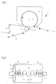
- FIG. 1 shows in a very highly schematic side view of a section of a machine 1, which is suitable for producing a fibrous web 2.
- the papers that can be produced with this type of machine 1 are referred to as hygiene or tissue papers.
- the machine 1 comprises a drying cylinder 3, which according to common nomenclature is also referred to as Yankee cylinder 3, and a drying hood 4, which encloses the Yankee cylinder 3 at least partially.
- a drying cylinder 3 which according to common nomenclature is also referred to as Yankee cylinder 3, and a drying hood 4, which encloses the Yankee cylinder 3 at least partially.
- the fibrous web 2 is - from a in Fig. 1 not shown forming part coming - in the in Fig. 1
- Direction marked with arrows on one Paper machine clothing 5 is guided in the direction of the Yankee cylinder 3 and transferred by means of a press roller 6 to the Yankee cylinder 3.
- a pre-dewatering of the fibrous web 2 takes place before it is dried on the Yankee cylinder 3.
- the main focus is on the fact that the fibrous web 2 is not compacted too much and does not lose its so-called. Bulk, which is crucial for the subsequent properties of the tissue paper.
- the Yankee cylinder 3 is heated from the inside by means not shown measures by means of steam, so that after passing through a nip 7 between the press roller 6 and Yankee cylinder 3 still existing in the fibrous web 2 water can be removed for the most part.
- the drying hood 4 serves to retain heat in the area of the Yankee cylinder 3 in order to improve the drying capacity in relation to the energy input.
- the fibrous web 2 is removed by means of a creping doctor 8 from the Yankee cylinder 3 and further guided in the direction of unrolling not shown.
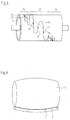
- FIG. 4 is highly schematized and for clarity exaggerated the situation between the press roller 6 and the Yankee cylinder 3 shown.
- the Yankee cylinder 3 has a convex deformation. Accordingly, the surface of the press roller 6 may have a slightly concave deformation, but not fail to the same extent as the deformation of the Yankee cylinder 3. This is due to the fact that although the roll cover 10 of the press roll 6 is designed as an elastic cover, the press roll is not cambered. Accordingly, the pressure roller 6 seen in the cross-machine direction in a central region 13, a higher pressure than in marginal areas 12, so that it is desirable to strengthen the monitoring of the marginal areas 12.
- the pressure roller 6 is provided with suitable sensors 11, which make it possible to continuously monitor the pressure and / or the temperature in the nip 7.
- a roll having an elastic roll cover 10 applied on a hard roll core 9 is provided.
- the roll cover 10 for example, rubber or polyurethane are suitable, while the roll core 9 may consist for example of metal or a fiber composite material.
- the roll cover 10 is kept soft to obtain the bulk of the fibrous web 2.
- the sensors 11 are preferably designed in the form of fiber Bragg sensors.
- 14 so-called Bragg gratings are written in an optical waveguide, which each have a reflective effect for predetermined wavelengths when light is transmitted through the optical waveguide 14.
- the optical fiber 14 is usually a glass fiber.
- an optical waveguide 14 which has sensors 11 at defined positions. Due to their characteristics, the sensors 11 must be oriented substantially in a circumferential direction of the press roller 6. An angle between the longitudinal extent of the sensors 11 and the circumferential direction should be less than 80 °, preferably less than 60 °, particularly preferably less than 45 °.
- the optical waveguide 14 is moved meandering for this reason, since glass fibers usually withstand very high tensile forces, but not under small radii may be bent.
- the meandering installation is in FIG. 2 good to see.
- the sensors 11 are arranged in a region 15 which extends substantially across the width of the press roll 6 and has an extension of less than 15 cm, preferably less than 5 cm, particularly preferably less than 3 cm.
- the sensors 11 are thus arranged substantially on a line.
- the sensors in the peripheral regions 12 are spaced apart from one another with respect to the central region 13 at different distances. How out FIG. 2 As can be seen, the distances between the individual sensors 11 in the marginal areas 12 are smaller than in the central area 13. This ensures close monitoring of the pressures and / or temperatures in the marginal areas 12. In the central region 13, the distances between the sensors 11 to each other may be somewhat further selected, since in this area, the above-mentioned deformations of the Yankee cylinder 3 are not so pronounced or partially compensated by cambering and crowning.
- the sensors 11 are formed substantially over the entire width of the fibrous web 2 and preferably over the entire width of the roll cover 10. In addition, sensors 11 may also be provided in the region of a so-called edge relief, where the radial thickness of the roll cover 10 decreases, in order to obtain measured values when the fibrous web 2 is moving.
- FIG. 3 is shown a further embodiment of the inventive measures.
- the optical waveguide 14 is arranged in a helical shape, which can extend over the entire surface of the roll cover 10. It can also be provided several turns.
- the sensors 11 are again, as already in FIG. 2 described in one narrow range 16 of similar dimensions as in FIG. 2 arranged and are essentially in line. Also, their orientation with respect to the circumferential direction of the press roll 6 follows the same requirements.
- optical waveguides 14 which can be distributed over the surface of the press roller 6. These can either be as in FIG. 2 be arranged in the cross-machine direction substantially parallel to the direction of the roll axis or as in FIG. 3 in the form of helical turns. It is conceivable, for example, to provide a number of four optical waveguides 14, which can be arranged at uniform intervals of 90 ° to each other around the press roller 6.
- the Bragg gratings can be reflective for the same or different wavelengths. If a plurality of optical waveguides 14 are laid, different wavelengths can be selected for each of the optical waveguides 14, for example, in order to simplify the evaluation.
- the arrangement of the optical waveguide 14 is preferably carried out between the roll core 9 and the roll cover 10 or between different layers of the roll cover 10, if it provides multiple layers, or even embedded in a layer.
- At least one end 17 of the at least one optical waveguide 14 is led out of the press roller 6 and connected to an evaluation unit (not shown).
Landscapes
- Physics & Mathematics (AREA)
- General Physics & Mathematics (AREA)
- Chemical & Material Sciences (AREA)
- Analytical Chemistry (AREA)
- Paper (AREA)
Claims (11)
- Machine (1) pour la production et/ou le traitement d'une bande de matière fibreuse (2), en particulier d'une bande d'essuie-tout, avec un rouleau de pression (6) et un rouleau opposé (3), qui est réalisé en forme de cylindre frictionneur (3) et qui forme avec le rouleau de pression (6) une emprise (7), dans laquelle sa surface latérale présente un contour s'étendant dans la direction transversale de la machine qui change lors du fonctionnement de la machine (1) par rapport à l'arrêt de la machine (1), et dans laquelle le rouleau de pression (6) présente un noyau de rouleau (9) et une enveloppe de rouleau (10) entourant le noyau de rouleau (9) et plusieurs capteurs de pression et/ou de température (11) sont disposés dans l'enveloppe de rouleau (10) et/ou entre le noyau de rouleau (9) et l'enveloppe de rouleau (10), dans laquelle le rouleau opposé est chauffé par l'intérieur au moyen de vapeur, et le contour du rouleau opposé (3) en fonctionnement, considéré dans la direction transversale de la machine, est au moins localement courbe, en particulier au moins localement concave ou convexe, et les capteurs de pression et/ou de température (11) dans la direction transversale de la machine du rouleau de pression (6) sont au moins localement espacés différemment l'un de l'autre, dans laquelle les capteurs de pression et/ou de température (11) présentent dans des régions de bord (12) du rouleau de pression (6) en considérant la direction transversale de la machine des distances plus petites l'un par rapport à l'autre que dans une région centrale (13) du rouleau de pression (6) considéré dans la direction transversale de la machine.
- Machine selon la revendication 1, caractérisée en ce qu'au moins quelques-uns des capteurs de pression et/ou de température (11) sont réalisés sous forme de réseau de Bragg à fibre, qui sont disposés sur au moins un guide d'ondes lumineuses (14), de telle manière que des sections dudit au moins un guide d'ondes lumineuses (14), qui contiennent respectivement un réseau de Bragg à fibre, alternent avec des sections dudit au moins un guide d'ondes lumineuses (14), qui sont dépourvues de réseaux de Bragg à fibre, le long de l'extension du guide d'ondes lumineuses (14).
- Machine selon la revendication 2, caractérisée en ce que des sections dudit au moins un guide d'ondes lumineuses (14), qui contiennent respectivement un réseau de Bragg à fibre, forment avec une direction périphérique du rouleau de pression (6) un angle inférieur à 80° et en particulier inférieur à 60° et de préférence encore inférieur à 45°.
- Machine selon la revendication 2 ou 3, caractérisée en ce que les distances entre les sections du même guide d'ondes lumineuses (14), qui contiennent respectivement un réseau de Bragg à fibre, dans les régions de bord (12) considérées dans la direction transversale de la machine, diminuent au moins localement avec l'augmentation de l'éloignement de la région centrale (13) du rouleau de pression (6) considéré dans la direction transversale de la machine.
- Machine selon l'une quelconque des revendications 2 à 4, caractérisée en ce que des sections du même guide d'ondes lumineuses (14), qui contiennent respectivement un réseau de Bragg à fibre, sont disposées de façon voisine, considérées dans la direction transversale de la machine.
- Machine selon l'une quelconque des revendications 2 à 5, caractérisée en ce que des sections du même guide d'ondes lumineuses (14), qui contiennent respectivement un réseau de Bragg à fibre, sont disposées dans une région (15) s'étendant sur au moins une partie de la longueur dans la direction transversale de la machine du rouleau de pression (6) dans une dans la direction transversale, dont l'extension dans la direction périphérique vaut moins de 15 cm et en particulier moins de 5 cm et de préférence encore moins de 3 cm.
- Machine selon l'une quelconque des revendications 2 à 5, caractérisée en ce que des sections du même guide d'ondes lumineuses (14), qui contiennent respectivement un réseau de Bragg à fibre, sont disposées le long d'une courbe hélicoïdale (16) tracée sur la surface du rouleau de pression (6), dans laquelle un écart de la courbe hélicoïdale aussi bien dans la direction transversale de la machine du rouleau de pression (6) que dans la direction périphérique du rouleau de pression (6) vaut moins de 15 cm et en particulier moins de 5 cm et de préférence encore moins de 3 cm.
- Machine selon l'une quelconque des revendications 2 à 7, caractérisée en ce que des réseaux de Bragg à fibre du même guide d'ondes lumineuses (14) espacés dans la direction d'extension dudit au moins un guide d'ondes lumineuses (14) sont réalisés de façon à réfléchir une lumière de différentes longueurs d'onde.
- Machine selon l'une quelconque des revendications 2 à 7, caractérisée en ce que des réseaux de Bragg à fibre du même guide d'ondes lumineuses (14) espacés dans la direction d'extension dudit au moins un guide d'ondes lumineuses (14) sont réalisés de façon à réfléchir une lumière de la même longueur d'onde.
- Machine selon l'une quelconque des revendications 2 à 9, caractérisée en ce qu'au moins une extrémité (17) dudit au moins un guide d'ondes lumineuses (14) est menée hors du rouleau de pression (6).
- Machine selon l'une quelconque des revendications 2 à 10, caractérisée en ce que l'enveloppe de rouleau (10) présente plusieurs couches et ledit au moins un guide d'ondes lumineuses (14) est disposé entre deux couches de l'enveloppe de rouleau (10) ou est logé dans une des multiples couches.
Applications Claiming Priority (2)
| Application Number | Priority Date | Filing Date | Title |
|---|---|---|---|
| DE201210203035 DE102012203035A1 (de) | 2012-02-28 | 2012-02-28 | Maschine zur Herstellung einer Faserstoffbahn |
| PCT/EP2013/053793 WO2013127777A1 (fr) | 2012-02-28 | 2013-02-26 | Machine de production d'une bande fibreuse |
Publications (2)
| Publication Number | Publication Date |
|---|---|
| EP2820187A1 EP2820187A1 (fr) | 2015-01-07 |
| EP2820187B1 true EP2820187B1 (fr) | 2017-08-09 |
Family
ID=47998389
Family Applications (1)
| Application Number | Title | Priority Date | Filing Date |
|---|---|---|---|
| EP13712490.5A Active EP2820187B1 (fr) | 2012-02-28 | 2013-02-26 | Machine de production d'une bande fibreuse |
Country Status (5)
| Country | Link |
|---|---|
| US (1) | US9121136B2 (fr) |
| EP (1) | EP2820187B1 (fr) |
| CN (1) | CN204343097U (fr) |
| DE (1) | DE102012203035A1 (fr) |
| WO (1) | WO2013127777A1 (fr) |
Families Citing this family (14)
| Publication number | Priority date | Publication date | Assignee | Title |
|---|---|---|---|---|
| DE102012203035A1 (de) * | 2012-02-28 | 2013-08-29 | Voith Patent Gmbh | Maschine zur Herstellung einer Faserstoffbahn |
| US9540769B2 (en) | 2013-03-11 | 2017-01-10 | International Paper Company | Method and apparatus for measuring and removing rotational variability from a nip pressure profile of a covered roll of a nip press |
| DE102013205450B3 (de) * | 2013-03-27 | 2014-07-10 | Voith Patent Gmbh | Walze |
| TWI620703B (zh) * | 2016-07-25 | 2018-04-11 | 財團法人工業技術研究院 | 具有壓力感測器的滾輪及捲對捲裝置 |
| DE102017106815A1 (de) | 2017-02-07 | 2018-08-09 | Voith Patent Gmbh | Sensorwalze |
| CN107631811B (zh) * | 2017-08-28 | 2020-06-16 | 中国科学院宁波材料技术与工程研究所 | 一种辊面温度在线检测方法及其装置 |
| DE102017127932A1 (de) | 2017-11-27 | 2019-05-29 | Voith Patent Gmbh | Verfahren |
| FI129914B (fi) * | 2018-10-26 | 2022-10-31 | Valmet Technologies Oy | Menetelmä, järjestelmä, pyörivä kone-elin ja tietokoneohjelmatuote rainaradan kosteuden mittaamiseksi tissuekoneella |
| SE543393C2 (en) * | 2019-06-18 | 2020-12-29 | Ircon Drying Systems Ab | Arrangement and method for measuring the temperature of a web, including computer program, computer readable medium and control unit |
| DE102019120052A1 (de) * | 2019-07-24 | 2021-01-28 | SchäferRolls GmbH & Co. KG | Technische Walze, insbesondere für die Papierherstellung, Verfahren zum Einbringen einer Polymerfaser in ein Leerrohr einer technischen Walze und Verwendung einer Polymerfaser |
| US11707906B2 (en) | 2020-08-27 | 2023-07-25 | Buckman Laboratories International, Inc. | Predictive control of Yankee dryer chemistry and creped product quality |
| CN113463425A (zh) * | 2021-06-03 | 2021-10-01 | 江辉辉 | 一种可以调节纸张压榨程度的造纸机保护装置 |
| FI130604B (en) * | 2022-02-10 | 2023-12-11 | Valmet Technologies Oy | The measurement system of the pulp-making device |
| CN118974672A (zh) | 2022-03-24 | 2024-11-15 | 巴克曼实验室国际公司 | 用于关于在线传感器的追溯和自动验证或校正动作的系统和方法 |
Family Cites Families (17)
| Publication number | Priority date | Publication date | Assignee | Title |
|---|---|---|---|---|
| US5048353A (en) * | 1990-03-01 | 1991-09-17 | Beloit Corporation | Method and apparatus for roll profile measurement |
| FI86771C (fi) * | 1991-10-14 | 1992-10-12 | Valmet Paper Machinery Inc | Foerfarande och anordning foer maetning av nypkraften och/eller -trycket av ett nyp som bildas av en roterande vals eller ett band som anvaends vid framstaellning av papper |
| US5592875A (en) * | 1994-09-16 | 1997-01-14 | Stowe Woodward Licensco, Inc. | Roll having means for determining pressure distribution |
| US5562027A (en) * | 1995-02-16 | 1996-10-08 | Stowe Woodward Licensco, Inc. | Dynamic nip pressure and temperature sensing system |
| US6568285B1 (en) * | 1998-02-19 | 2003-05-27 | Stowe Woodward Llc | Nip width sensing system and method |
| DE10203321A1 (de) * | 2002-01-29 | 2003-08-14 | Voith Paper Patent Gmbh | Messwalze |
| BRPI0511017A (pt) * | 2004-05-14 | 2007-11-27 | Stowe Woodward Llc | sistema e método para determinar caracterìsticas de dois rolos configurados em uma prensa de passe, e, tira para uso em uma prensa de passe entre dois rolos |
| BRPI0510978A (pt) * | 2004-05-14 | 2007-11-27 | Stowe Woodward Llc | sistema para medição de largura de espaço para um espaço presente entre dois rolos, e, método para determinar a largura de um espaço posicionado entre dois rolos |
| US7392715B2 (en) * | 2004-10-29 | 2008-07-01 | Stowe Woodward Ag | Wireless sensors in roll covers |
| DE102007000846A1 (de) * | 2007-10-11 | 2009-04-16 | Voith Patent Gmbh | Papiermaschinenwalze |
| BRPI0822792B1 (pt) * | 2008-09-23 | 2019-04-16 | Voith Patent Gmbh | Rolo industrial com sistema sensor de cobertura do rolo ótico |
| US8346501B2 (en) * | 2009-06-22 | 2013-01-01 | Stowe Woodward, L.L.C. | Industrial roll with sensors arranged to self-identify angular location |
| US8475347B2 (en) * | 2010-06-04 | 2013-07-02 | Stowe Woodward Licensco, Llc | Industrial roll with multiple sensor arrays |
| EP2678652A1 (fr) * | 2011-02-25 | 2014-01-01 | Voith Patent GmbH | Cylindre pour machines à papier, avec capteurs à fibres de bragg |
| BR112013030716A2 (pt) * | 2011-06-02 | 2019-09-24 | Stowe Woodward Licensco Llc | método e sistema para determinar a largura de um interstício formado por um rolo industrial e uma estrutura de associação, e, produto de programa de computador. |
| DE102012203035A1 (de) * | 2012-02-28 | 2013-08-29 | Voith Patent Gmbh | Maschine zur Herstellung einer Faserstoffbahn |
| US9540769B2 (en) * | 2013-03-11 | 2017-01-10 | International Paper Company | Method and apparatus for measuring and removing rotational variability from a nip pressure profile of a covered roll of a nip press |
-
2012
- 2012-02-28 DE DE201210203035 patent/DE102012203035A1/de not_active Ceased
-
2013
- 2013-02-26 US US14/381,670 patent/US9121136B2/en active Active
- 2013-02-26 EP EP13712490.5A patent/EP2820187B1/fr active Active
- 2013-02-26 WO PCT/EP2013/053793 patent/WO2013127777A1/fr not_active Ceased
- 2013-02-26 CN CN201390000281.XU patent/CN204343097U/zh not_active Expired - Lifetime
Non-Patent Citations (1)
| Title |
|---|
| None * |
Also Published As
| Publication number | Publication date |
|---|---|
| US9121136B2 (en) | 2015-09-01 |
| CN204343097U (zh) | 2015-05-20 |
| US20150013927A1 (en) | 2015-01-15 |
| EP2820187A1 (fr) | 2015-01-07 |
| DE102012203035A1 (de) | 2013-08-29 |
| WO2013127777A1 (fr) | 2013-09-06 |
Similar Documents
| Publication | Publication Date | Title |
|---|---|---|
| EP2820187B1 (fr) | Machine de production d'une bande fibreuse | |
| DE69627639T2 (de) | Sensorsystem zum messen von dynamischen druck in einem spalt zwischen zwei walzen | |
| DE60211331T3 (de) | Schuhpressenband mit einem system zur erfassung von betriebsparametern | |
| EP2678652A1 (fr) | Cylindre pour machines à papier, avec capteurs à fibres de bragg | |
| DE69332457T2 (de) | Papiermachervorrichtung mit semi-kontinuierlichem Muster | |
| WO2013104600A1 (fr) | Rouleau à capteurs pour machine de traitement de bande | |
| EP3167115B1 (fr) | Machine pour la production d'une bande de matière fibreuse | |
| DE19962706A1 (de) | Pressenpartie | |
| DE102010031450A1 (de) | Verfahren und Maschine zur Herstellung einer Faserstoffbahn | |
| DE102008000267A1 (de) | Verfahren zur Entwässerung und Entwässerungsvorrichtung | |
| EP3662107B1 (fr) | Chemise de presse et son utilisation ainsi que rouleau de presse et presse à sabot | |
| DE102012202245A1 (de) | Papiermaschinen-Walze mit Faser-Bragg-Sensoren | |
| WO2020057795A1 (fr) | Manchon de presse, son utilisation et rouleau de presse, presse à sabot et utilisation d'un fil de renfort dans un manchon de presse | |
| WO2014020049A1 (fr) | Procédé pour équiper un rouleau de capteurs à fibre optique, système de capteurs à fibre optique et rouleau comprenant un système de capteurs à fibre optique | |
| EP3011102B1 (fr) | Rouleau | |
| DE112007003105T5 (de) | Messwalze für eine Faserbahnmaschine, vorteilhafterweise für einen Rollapparat für eine Faserbahn | |
| DE102014208159A1 (de) | Anpresseinheit | |
| WO2021058171A1 (fr) | Chemise de presse, son utilisation, rouleau de presse et presse à sabot | |
| WO2020057793A1 (fr) | Manchon de presse, son utilisation et rouleau de presse, presse à sabot et utilisation d'un fil de renfort dans un manchon de presse | |
| EP1348804B1 (fr) | Machine pour fabriquer du papier de soie comprenant une presse à patin | |
| DE102007042201A1 (de) | Band für eine Maschine zur Herstellung von Bahnmaterial, insbesondere Papier oder Karton | |
| DE102010031447A1 (de) | Verfahren und Maschine zur Herstellung einer Faserstoffbahn | |
| EP1643033B1 (fr) | Dispositif de pressage d'une section de presse d'une machine de fabrication d'une bande fibreuse | |
| DE102014204203A1 (de) | Bespannung | |
| DE102019121067A1 (de) | Vorrichtung zur Herstellung einer mehrlagigen Faserstoffbahn |
Legal Events
| Date | Code | Title | Description |
|---|---|---|---|
| PUAI | Public reference made under article 153(3) epc to a published international application that has entered the european phase |
Free format text: ORIGINAL CODE: 0009012 |
|
| 17P | Request for examination filed |
Effective date: 20140929 |
|
| AK | Designated contracting states |
Kind code of ref document: A1 Designated state(s): AL AT BE BG CH CY CZ DE DK EE ES FI FR GB GR HR HU IE IS IT LI LT LU LV MC MK MT NL NO PL PT RO RS SE SI SK SM TR |
|
| AX | Request for extension of the european patent |
Extension state: BA ME |
|
| DAX | Request for extension of the european patent (deleted) | ||
| 17Q | First examination report despatched |
Effective date: 20160506 |
|
| REG | Reference to a national code |
Ref country code: DE Ref legal event code: R079 Ref document number: 502013008010 Country of ref document: DE Free format text: PREVIOUS MAIN CLASS: D21F0003060000 Ipc: G01K0001020000 |
|
| GRAP | Despatch of communication of intention to grant a patent |
Free format text: ORIGINAL CODE: EPIDOSNIGR1 |
|
| INTG | Intention to grant announced |
Effective date: 20170310 |
|
| RIC1 | Information provided on ipc code assigned before grant |
Ipc: G01L 1/24 20060101ALI20170224BHEP Ipc: G01K 13/08 20060101ALI20170224BHEP Ipc: D21F 5/18 20060101ALI20170224BHEP Ipc: D21F 3/08 20060101ALI20170224BHEP Ipc: G01K 1/02 20060101AFI20170224BHEP Ipc: D21F 3/06 20060101ALI20170224BHEP Ipc: G01L 5/00 20060101ALI20170224BHEP Ipc: D21G 1/02 20060101ALI20170224BHEP |
|
| GRAS | Grant fee paid |
Free format text: ORIGINAL CODE: EPIDOSNIGR3 |
|
| GRAA | (expected) grant |
Free format text: ORIGINAL CODE: 0009210 |
|
| AK | Designated contracting states |
Kind code of ref document: B1 Designated state(s): AL AT BE BG CH CY CZ DE DK EE ES FI FR GB GR HR HU IE IS IT LI LT LU LV MC MK MT NL NO PL PT RO RS SE SI SK SM TR |
|
| REG | Reference to a national code |
Ref country code: GB Ref legal event code: FG4D Free format text: NOT ENGLISH |
|
| REG | Reference to a national code |
Ref country code: CH Ref legal event code: EP Ref country code: AT Ref legal event code: REF Ref document number: 917356 Country of ref document: AT Kind code of ref document: T Effective date: 20170815 |
|
| REG | Reference to a national code |
Ref country code: IE Ref legal event code: FG4D Free format text: LANGUAGE OF EP DOCUMENT: GERMAN |
|
| REG | Reference to a national code |
Ref country code: DE Ref legal event code: R096 Ref document number: 502013008010 Country of ref document: DE |
|
| REG | Reference to a national code |
Ref country code: NL Ref legal event code: MP Effective date: 20170809 |
|
| REG | Reference to a national code |
Ref country code: LT Ref legal event code: MG4D |
|
| PG25 | Lapsed in a contracting state [announced via postgrant information from national office to epo] |
Ref country code: NL Free format text: LAPSE BECAUSE OF FAILURE TO SUBMIT A TRANSLATION OF THE DESCRIPTION OR TO PAY THE FEE WITHIN THE PRESCRIBED TIME-LIMIT Effective date: 20170809 Ref country code: NO Free format text: LAPSE BECAUSE OF FAILURE TO SUBMIT A TRANSLATION OF THE DESCRIPTION OR TO PAY THE FEE WITHIN THE PRESCRIBED TIME-LIMIT Effective date: 20171109 Ref country code: SE Free format text: LAPSE BECAUSE OF FAILURE TO SUBMIT A TRANSLATION OF THE DESCRIPTION OR TO PAY THE FEE WITHIN THE PRESCRIBED TIME-LIMIT Effective date: 20170809 Ref country code: HR Free format text: LAPSE BECAUSE OF FAILURE TO SUBMIT A TRANSLATION OF THE DESCRIPTION OR TO PAY THE FEE WITHIN THE PRESCRIBED TIME-LIMIT Effective date: 20170809 Ref country code: LT Free format text: LAPSE BECAUSE OF FAILURE TO SUBMIT A TRANSLATION OF THE DESCRIPTION OR TO PAY THE FEE WITHIN THE PRESCRIBED TIME-LIMIT Effective date: 20170809 |
|
| PG25 | Lapsed in a contracting state [announced via postgrant information from national office to epo] |
Ref country code: GR Free format text: LAPSE BECAUSE OF FAILURE TO SUBMIT A TRANSLATION OF THE DESCRIPTION OR TO PAY THE FEE WITHIN THE PRESCRIBED TIME-LIMIT Effective date: 20171110 Ref country code: RS Free format text: LAPSE BECAUSE OF FAILURE TO SUBMIT A TRANSLATION OF THE DESCRIPTION OR TO PAY THE FEE WITHIN THE PRESCRIBED TIME-LIMIT Effective date: 20170809 Ref country code: ES Free format text: LAPSE BECAUSE OF FAILURE TO SUBMIT A TRANSLATION OF THE DESCRIPTION OR TO PAY THE FEE WITHIN THE PRESCRIBED TIME-LIMIT Effective date: 20170809 Ref country code: LV Free format text: LAPSE BECAUSE OF FAILURE TO SUBMIT A TRANSLATION OF THE DESCRIPTION OR TO PAY THE FEE WITHIN THE PRESCRIBED TIME-LIMIT Effective date: 20170809 Ref country code: PL Free format text: LAPSE BECAUSE OF FAILURE TO SUBMIT A TRANSLATION OF THE DESCRIPTION OR TO PAY THE FEE WITHIN THE PRESCRIBED TIME-LIMIT Effective date: 20170809 Ref country code: IS Free format text: LAPSE BECAUSE OF FAILURE TO SUBMIT A TRANSLATION OF THE DESCRIPTION OR TO PAY THE FEE WITHIN THE PRESCRIBED TIME-LIMIT Effective date: 20171209 Ref country code: BG Free format text: LAPSE BECAUSE OF FAILURE TO SUBMIT A TRANSLATION OF THE DESCRIPTION OR TO PAY THE FEE WITHIN THE PRESCRIBED TIME-LIMIT Effective date: 20171109 |
|
| PG25 | Lapsed in a contracting state [announced via postgrant information from national office to epo] |
Ref country code: CZ Free format text: LAPSE BECAUSE OF FAILURE TO SUBMIT A TRANSLATION OF THE DESCRIPTION OR TO PAY THE FEE WITHIN THE PRESCRIBED TIME-LIMIT Effective date: 20170809 Ref country code: DK Free format text: LAPSE BECAUSE OF FAILURE TO SUBMIT A TRANSLATION OF THE DESCRIPTION OR TO PAY THE FEE WITHIN THE PRESCRIBED TIME-LIMIT Effective date: 20170809 Ref country code: RO Free format text: LAPSE BECAUSE OF FAILURE TO SUBMIT A TRANSLATION OF THE DESCRIPTION OR TO PAY THE FEE WITHIN THE PRESCRIBED TIME-LIMIT Effective date: 20170809 |
|
| REG | Reference to a national code |
Ref country code: DE Ref legal event code: R097 Ref document number: 502013008010 Country of ref document: DE |
|
| PG25 | Lapsed in a contracting state [announced via postgrant information from national office to epo] |
Ref country code: SK Free format text: LAPSE BECAUSE OF FAILURE TO SUBMIT A TRANSLATION OF THE DESCRIPTION OR TO PAY THE FEE WITHIN THE PRESCRIBED TIME-LIMIT Effective date: 20170809 Ref country code: EE Free format text: LAPSE BECAUSE OF FAILURE TO SUBMIT A TRANSLATION OF THE DESCRIPTION OR TO PAY THE FEE WITHIN THE PRESCRIBED TIME-LIMIT Effective date: 20170809 Ref country code: SM Free format text: LAPSE BECAUSE OF FAILURE TO SUBMIT A TRANSLATION OF THE DESCRIPTION OR TO PAY THE FEE WITHIN THE PRESCRIBED TIME-LIMIT Effective date: 20170809 Ref country code: IT Free format text: LAPSE BECAUSE OF FAILURE TO SUBMIT A TRANSLATION OF THE DESCRIPTION OR TO PAY THE FEE WITHIN THE PRESCRIBED TIME-LIMIT Effective date: 20170809 |
|
| PLBE | No opposition filed within time limit |
Free format text: ORIGINAL CODE: 0009261 |
|
| STAA | Information on the status of an ep patent application or granted ep patent |
Free format text: STATUS: NO OPPOSITION FILED WITHIN TIME LIMIT |
|
| 26N | No opposition filed |
Effective date: 20180511 |
|
| PG25 | Lapsed in a contracting state [announced via postgrant information from national office to epo] |
Ref country code: SI Free format text: LAPSE BECAUSE OF FAILURE TO SUBMIT A TRANSLATION OF THE DESCRIPTION OR TO PAY THE FEE WITHIN THE PRESCRIBED TIME-LIMIT Effective date: 20170809 |
|
| REG | Reference to a national code |
Ref country code: CH Ref legal event code: PL |
|
| PG25 | Lapsed in a contracting state [announced via postgrant information from national office to epo] |
Ref country code: MC Free format text: LAPSE BECAUSE OF FAILURE TO SUBMIT A TRANSLATION OF THE DESCRIPTION OR TO PAY THE FEE WITHIN THE PRESCRIBED TIME-LIMIT Effective date: 20170809 Ref country code: MT Free format text: LAPSE BECAUSE OF FAILURE TO SUBMIT A TRANSLATION OF THE DESCRIPTION OR TO PAY THE FEE WITHIN THE PRESCRIBED TIME-LIMIT Effective date: 20170809 |
|
| GBPC | Gb: european patent ceased through non-payment of renewal fee |
Effective date: 20180226 |
|
| REG | Reference to a national code |
Ref country code: IE Ref legal event code: MM4A |
|
| REG | Reference to a national code |
Ref country code: BE Ref legal event code: MM Effective date: 20180228 |
|
| PG25 | Lapsed in a contracting state [announced via postgrant information from national office to epo] |
Ref country code: LU Free format text: LAPSE BECAUSE OF NON-PAYMENT OF DUE FEES Effective date: 20180226 Ref country code: CH Free format text: LAPSE BECAUSE OF NON-PAYMENT OF DUE FEES Effective date: 20180228 Ref country code: LI Free format text: LAPSE BECAUSE OF NON-PAYMENT OF DUE FEES Effective date: 20180228 |
|
| REG | Reference to a national code |
Ref country code: FR Ref legal event code: ST Effective date: 20181031 |
|
| PG25 | Lapsed in a contracting state [announced via postgrant information from national office to epo] |
Ref country code: IE Free format text: LAPSE BECAUSE OF NON-PAYMENT OF DUE FEES Effective date: 20180226 |
|
| PG25 | Lapsed in a contracting state [announced via postgrant information from national office to epo] |
Ref country code: GB Free format text: LAPSE BECAUSE OF NON-PAYMENT OF DUE FEES Effective date: 20180226 Ref country code: BE Free format text: LAPSE BECAUSE OF NON-PAYMENT OF DUE FEES Effective date: 20180228 Ref country code: FR Free format text: LAPSE BECAUSE OF NON-PAYMENT OF DUE FEES Effective date: 20180228 |
|
| PG25 | Lapsed in a contracting state [announced via postgrant information from national office to epo] |
Ref country code: TR Free format text: LAPSE BECAUSE OF FAILURE TO SUBMIT A TRANSLATION OF THE DESCRIPTION OR TO PAY THE FEE WITHIN THE PRESCRIBED TIME-LIMIT Effective date: 20170809 |
|
| PG25 | Lapsed in a contracting state [announced via postgrant information from national office to epo] |
Ref country code: HU Free format text: LAPSE BECAUSE OF FAILURE TO SUBMIT A TRANSLATION OF THE DESCRIPTION OR TO PAY THE FEE WITHIN THE PRESCRIBED TIME-LIMIT; INVALID AB INITIO Effective date: 20130226 Ref country code: PT Free format text: LAPSE BECAUSE OF FAILURE TO SUBMIT A TRANSLATION OF THE DESCRIPTION OR TO PAY THE FEE WITHIN THE PRESCRIBED TIME-LIMIT Effective date: 20170809 |
|
| PG25 | Lapsed in a contracting state [announced via postgrant information from national office to epo] |
Ref country code: MK Free format text: LAPSE BECAUSE OF NON-PAYMENT OF DUE FEES Effective date: 20170809 Ref country code: CY Free format text: LAPSE BECAUSE OF FAILURE TO SUBMIT A TRANSLATION OF THE DESCRIPTION OR TO PAY THE FEE WITHIN THE PRESCRIBED TIME-LIMIT Effective date: 20170809 |
|
| PG25 | Lapsed in a contracting state [announced via postgrant information from national office to epo] |
Ref country code: AL Free format text: LAPSE BECAUSE OF FAILURE TO SUBMIT A TRANSLATION OF THE DESCRIPTION OR TO PAY THE FEE WITHIN THE PRESCRIBED TIME-LIMIT Effective date: 20170809 |
|
| PGFP | Annual fee paid to national office [announced via postgrant information from national office to epo] |
Ref country code: AT Payment date: 20230217 Year of fee payment: 11 |
|
| REG | Reference to a national code |
Ref country code: AT Ref legal event code: MM01 Ref document number: 917356 Country of ref document: AT Kind code of ref document: T Effective date: 20240226 |
|
| PG25 | Lapsed in a contracting state [announced via postgrant information from national office to epo] |
Ref country code: AT Free format text: LAPSE BECAUSE OF NON-PAYMENT OF DUE FEES Effective date: 20240226 |
|
| PG25 | Lapsed in a contracting state [announced via postgrant information from national office to epo] |
Ref country code: AT Free format text: LAPSE BECAUSE OF NON-PAYMENT OF DUE FEES Effective date: 20240226 |
|
| PGFP | Annual fee paid to national office [announced via postgrant information from national office to epo] |
Ref country code: FI Payment date: 20250220 Year of fee payment: 13 |
|
| PGFP | Annual fee paid to national office [announced via postgrant information from national office to epo] |
Ref country code: DE Payment date: 20260218 Year of fee payment: 14 |