EP2820295B1 - Zustandsüberwachung eines rotierenden systems auf der basis eines zeitgeprägten signals - Google Patents
Zustandsüberwachung eines rotierenden systems auf der basis eines zeitgeprägten signals Download PDFInfo
- Publication number
- EP2820295B1 EP2820295B1 EP13754992.9A EP13754992A EP2820295B1 EP 2820295 B1 EP2820295 B1 EP 2820295B1 EP 13754992 A EP13754992 A EP 13754992A EP 2820295 B1 EP2820295 B1 EP 2820295B1
- Authority
- EP
- European Patent Office
- Prior art keywords
- sensor
- monitoring
- monitoring device
- rotating system
- parameter
- Prior art date
- Legal status (The legal status is an assumption and is not a legal conclusion. Google has not performed a legal analysis and makes no representation as to the accuracy of the status listed.)
- Active
Links
Images


Classifications
-
- G—PHYSICS
- G05—CONTROLLING; REGULATING
- G05B—CONTROL OR REGULATING SYSTEMS IN GENERAL; FUNCTIONAL ELEMENTS OF SUCH SYSTEMS; MONITORING OR TESTING ARRANGEMENTS FOR SUCH SYSTEMS OR ELEMENTS
- G05B23/00—Testing or monitoring of control systems or parts thereof
- G05B23/02—Electric testing or monitoring
- G05B23/0205—Electric testing or monitoring by means of a monitoring system capable of detecting and responding to faults
- G05B23/0218—Electric testing or monitoring by means of a monitoring system capable of detecting and responding to faults characterised by the fault detection method dealing with either existing or incipient faults
- G05B23/0224—Process history based detection method, e.g. whereby history implies the availability of large amounts of data
- G05B23/024—Quantitative history assessment, e.g. mathematical relationships between available data; Functions therefor; Principal component analysis [PCA]; Partial least square [PLS]; Statistical classifiers, e.g. Bayesian networks, linear regression or correlation analysis; Neural networks
-
- G—PHYSICS
- G01—MEASURING; TESTING
- G01M—TESTING STATIC OR DYNAMIC BALANCE OF MACHINES OR STRUCTURES; TESTING OF STRUCTURES OR APPARATUS, NOT OTHERWISE PROVIDED FOR
- G01M13/00—Testing of machine parts
-
- G—PHYSICS
- G01—MEASURING; TESTING
- G01P—MEASURING LINEAR OR ANGULAR SPEED, ACCELERATION, DECELERATION, OR SHOCK; INDICATING PRESENCE, ABSENCE, OR DIRECTION, OF MOVEMENT
- G01P3/00—Measuring linear or angular speed; Measuring differences of linear or angular speeds
Definitions
- the present invention generally relates to condition monitoring of a rotating system, specifically to improved analysis performed by a monitoring system based on a time stamped signal from a tachometer.
- Condition monitoring is widely applied to determine a current and possible future status of mechanical machinery, including for example rotational systems such as turbines, generators, railway, and other industry processing equipment.
- rotational systems such as turbines, generators, railway, and other industry processing equipment.
- data relating to temperature, rotation, vibration, etc is analyzed for determining a change in operation, possibly initiating predictive maintenance of the rotating system for securing a long lifetime as well as reducing down time in case of equipment failure.
- US2011/0020122 A1 An example of a monitoring system employing the above technique is disclosed in US2011/0020122 A1 , describing a computer implemented method where condition information from a plurality of condition detection sensors coupled to a wind turbine are received by a centralized wind turbine controller.
- an anomaly detection algorithm is applied to identify maintenance activities for the wind turbine as a function of both the wind turbine condition information and the wind turbine controller information.
- US2007/0043533 describes a method and monitoring system for tracking operational parameters of a drive train of a monitored system including a sensor affixed to the drive train.
- Each microprocessor of the sensor units may timestamp digital data values at each sensor unit. The timestamp can be transmitted with the digitized data from the sensor units to communicators and be used during downstream processing.
- WO 2009068034 A1 relates to a method of registering events in a wind power system comprising at least two data processors, wherein the data processors of said wind power system are mutually time synchronized, wherein events are registered in said at least two data processors, wherein the timing of said events registered in different of said at least two data processors is established according to said time synchronization.
- Events may be registered and preferably analyzed according to a common timing. This analyzing makes it possible to establish an analysis where events of different wind turbines are basically interrelated and where information regarding such interrelation is important or crucial for establishment of control or fault detection based on correctly timed events from different wind turbines.
- a measurement device for a rotating system comprising a first sensor arranged in the vicinity of a shaft of the rotating system, the first sensor being configured to generate a signal relating to a rotation of the shaft, and a control unit connected to the first sensor, wherein the control unit is further configured to form a first parameter based on the signal from the first sensor, determine a current time reference, form a data package comprising the first parameter and a time stamp relating to the current time reference, and distribute the data package to at least one monitoring device over a network connected to the control unit.
- the present invention is based on the realization that it may be possible to improve processing of condition related data by time stamping parameters relating to the rotation of a shaft of the rotating system, and distribute that information over a network to e.g. monitoring devices where further processing may be done.
- data from a sensor configured for providing indications of a rotation of the shaft is time stamped and arranged in a format suitable for distribution over a network, where at least one further electronic device, such as a monitoring device, may receive the information and include it in further calculations.
- at least one further electronic device such as a monitoring device
- Advantages includes the possibility to in a more generic way share the rotational related information between a large plurality of electronic devices, e.g. including monitoring devices, without having to resort to complicated wiring and amplifiers which is commonly used in prior art monitoring systems when rotational related information is distributed to more than one further electronic device or over a larger distance. Rather, according to the invention it may be possible to use an already available network, wired or wireless, for distributing the rotational related information.
- data package should be interpreted broadly, including different configurations and implementations.
- a stream of loss tolerant data could be generated, including e.g. a 'tuple' where measured parameter and time references are organized together for further distribution.
- the measurement device and the monitoring device are time synchronized, to a suitably extent. This may for example be achieved using a local time reference provided to the measurement device and further distributed to the monitoring device. However, it may also be possible to provide a global synchronization of the measurement device and the monitoring device, for example using an externally arranged source providing the current time reference.
- the measurement device may further comprise an interface connecting the control unit to the external time reference, for example being at least one of a GPS (or any similar satellite navigation system), a device providing terrestrial radio time signals, or a computer based time reference, e.g. a time server (UTC).
- at least one of the measurement device and the monitoring device may be configured to indicate if the two devices falls out of synch, e.g. if the time synchronization between the two devices differs with more than a predefined time duration.
- the first sensor may comprise at least one of a hall-effect sensor, eddy-current sensor and an optical sensor.
- a hall-effect sensor For generating the signal relating to a rotation of the shaft, the first sensor may comprise at least one of a hall-effect sensor, eddy-current sensor and an optical sensor.
- Other implementation for generating a tachometer signal may be possible and is considered to be within the scope of the invention.
- the measurement device as discussed above is comprised in a monitoring system according to claim 1, the monitoring system further comprising at least one monitoring device, and a network connecting the measurement device and the monitoring device.
- the monitoring device is configured to receive a data package from the measurement device, extract the first parameter and the thereto related time stamp, receive a second parameter from a second sensor connected to the monitoring device and arranged to monitor one of a plurality of predetermined operational conditions of the rotating system, and perform a time based correlation between the first and the second parameter.
- the monitoring device may be configured to comprise a buffer for storing a plurality of parameters from the second sensor.
- a buffer may be arranged to dynamically adjust its size depending on previously identified network delays.
- the monitoring device is used in relation to performing frequency, phase and/or order analysis of vibrations generated during operation of the rotating system.
- the second sensor is preferably a vibration sensor arranged to monitor a vibration of the rotating system.
- the vibration may for example relate to a shaft, main bearing, motor, gearbox, or any other element of the rotating system.
- failure of a rotating system, or specifically a main bearing of the rotating system tend to be the degradation of the bearing, which typically exhibits an increase in characteristic frequencies associated with the bearing geometries and constructions that accordingly may be identified through frequency, phase and/or order analysis.
- any dynamic signal that may make use of accurate measurements relating to the rotation of the shaft of the rotating system may be correlated with the rotational related data from the tachometer arranged in vicinity of the shaft of the rotating system.
- the second sensor may e.g. be a second tachometer sensor arranged at a distance from the first sensor and thereby allowing for determining a possible torsion of the shaft of the rotating system.
- the externally arranged device for example may be a management server for storing the determined condition.
- the external device may also be a condition communication device, such as a device providing a warning (e.g. a warning signal by means of sound and/or light) if a specific condition is determined and personnel is needed for handling the condition.
- the condition may also be provided to a display unit for illustrating the condition to e.g. an operator of the rotating system.
- the computer readable medium may be one of a removable nonvolatile random access memory, a hard disk drive, a floppy disk, a CD-ROM, a DVD-ROM, a USB memory, an SD memory card, or a similar computer readable medium known in the art.
- the measurement device 100 comprises a tachometer 102 and a control unit 104 configured to receive sensor data from the tachometer 102.
- the measurement device 100 is arranged to measure the rotational speed (or angle of rotation) of a shaft 106 of a rotating system 108, the rotating system 108 possibly further comprising a motor 110.
- the tachometer 102 is installed proximate the shaft 106, and configured to generate sensor data being indicative of the rotational speed of the shaft 106.
- the control unit 104 preferably has internal timing means for providing a current time reference.
- control unit 104 may comprise an interface for receiving a time reference for example from an external source, such as from an externally arranged network connected time server providing time synchronization for the control unit 104. Still further, the control unit 104 may receive a satellite based time reference (e.g. GPS signal or similar) providing time synchronization for the control unit 104 with even higher accuracy than what currently may be achieved using the network connected server.
- a satellite based time reference e.g. GPS signal or similar
- the measurement device 100 is illustrated as comprising separate parts (i.e. the tachometer 102 and the control unit 104). However, it should be noted that the parts may be integrated into one single structure, providing both the sensor and computation functionality.
- the control unit 104 may include a microprocessor, a microcontroller, a programmable digital signal processor or another programmable device.
- the control unit 104 may also, or instead, include an application specific integrated circuit (ASIC), reduced instruction set computer (RISC), a programmable gate array programmable array logic, a programmable logic device, or a digital signal processor.
- ASIC application specific integrated circuit
- RISC reduced instruction set computer
- the processor may further include computer executable code that controls operation of the programmable device, possibly stored within a storage element/memory of the control unit 104.
- the motor 110 will initiate a rotation of the shaft 106.
- the adjacently arranged tachometer 102 will start to generate a stream of data relating to at least one of the angle of rotation or the rotational speed of the shaft 106.
- the control unit 104 receives the data from the tachometer 102 and forms a first parameter based on the tachometer data, the parameter for example comprising the rotational speed, the angle of rotation, or an indication as to when a specific point of the shaft 106 passes the sensor element of the tachometer 102.
- the first parameter is packaged together with a time stamp being a current time reference, for forming a time stamped data package comprising information as to the rotation of the shaft 106, that may be further distributed to additional monitoring devices and/or equipment (not shown explicitly in Fig. 1 ) provided for monitoring for example the condition of operation of the rotating system 108.
- Fig. 2 there is provided a schematic illustration of a measurement system 200 for a rotating system 108 as shown in Fig. 1 .
- the measurement system 200 is provided for monitoring a condition of the rotating system 108, and comprises distributed monitoring elements in the form of the measurement device 100 as discussed above in relation to Fig.1 , as well as a further monitoring device 202, where the measurement device 100 and the monitoring device 202 are connected to each other by means of a network connection 204, for example using an Ethernet or Internet connection (being e.g. wired or wireless).
- the monitoring device 202 is time synchronized with the measurement device 100 for allowing proper time correlation of measurement values generated by sensors connected to the measurement device 100 as well as the monitoring device 202.
- the measurement device 100 comprise an interface for allowing the connection of a further sensor, e.g. a vibration sensor 206 arranged to monitor a level of vibration of the motor 110 of the rotating system 108.
- the vibration sensor 206 may comprise a displacement sensor, velocity sensor or accelerometer that is configured to provide information that represents the vibration of various components of the motor 110. Accelerometers are the most commonly used vibration sensors. The sensors may also provide information that indicates vibration, inclination, dynamic distance or the speed of various components within the motor 110.
- sensor data provided by the vibration sensor 206 may be used when forming a time stamped data package that may be distributed over the network connection 204 to further monitoring elements provided for monitoring the condition of the rotating system.
- the monitoring device 202 may be a similar device as the measurement device 100, e.g. comprising a control unit, or a more advanced computing device or server.
- the monitoring device 202 comprises interfaces for allowing connection of e.g. a plurality of vibration sensors 208, temperature sensor(s) (not shown), etc.
- the monitoring device 202 is provided a distance from the measurement device 100, and the vibration sensor 208 is arranged to monitor the vibration of e.g. a bearing for the shaft 106 of the rotating system 108.
- the monitoring device 202 further comprises a storage unit/memory for storing data from the vibration sensor 208, and is configured to, in a similar manner as discussed above, time stamp the data from the vibration sensor 208.
- the monitoring device 202 and the vibration sensor 208 are provided as separate parts. However, as discussed above, they may alo be integrated as one element.
- the rotating system 110 when the rotating system 110 is activate and the shaft 108 is rotating, data is generated by the sensors of the measurement device 100, including information relating to the speed of rotating of the shaft 108 (or angle of rotation) and vibration of the motor 108.
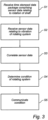
- the data is time stamped and packaged in a data package by the measurement device 100 and transmitted using the network connection 204 and received, S1, by the monitoring device 202. Further data from vibration sensor 208 is also received, S2, by the monitoring device 202.
- Advanced correlation, S3, and analysis of the data from the sensors of the measurement device 100 and the data from the sensors of the monitoring device 202 is made possible by the fact that data from all of the sensors are time stamped and thus may be time correlated with each other, for determining, S4, a condition of the rotating system 110 Specifically, even though the data from the measurement device 100 when transmitted to the monitoring device 202 possibly may be time delayed due to e.g. congestions within the network connection 204, the feature of time stamping the data from the sensors connected to the measurement device 100 allows this data to be exactly "time fitted" with data from the sensors connected to the monitoring device 202 being time stamped and stored in the memory of the monitoring device 202.
- the illustrated embodiment it may be possible to perform e.g. frequency, phase and/or order analysis based on all data provided by the sensors of the monitoring system 200, e.g. tachometer 102 and vibration sensors 206 and 208.
- the sensors of the monitoring system 200 e.g. tachometer 102 and vibration sensors 206 and 208.
- the analysis performed by the monitoring device 202 may take the rotational data from the tachometer sensor 102 into account as if the tachometer sensor 102 was connected directly to the monitoring device 202. Further, any network delays will be handled by the storage unit/memory, buffering data from e.g. the vibration sensor 208, for correct time fitting of data from different sensors. Additionally, similar types of analysis may be performed by even a large plurality of further monitoring devices (not shown), each connected to further condition monitoring sensors, that in a similar manner may take the data from the tachometer sensor 102 into account as if the tachometer sensor 102 was directly connected to each of the mentioned further monitoring devices.
- the data from the tachometer sensor 102 may be distributed to a plurality of devices for monitoring a condition of the rotating system 108, without having to resort to complicated additional tachometer data distribution networks involving e.g. expensive amplifiers, etc.
- the general concept of frequency, phase and order analysis of a rotating system is well known for the person skilled in the art and will not be further elaborated.
- the condition of the rotating system is communicated, S5, to an externally arranged device, such as a management server 210 where further analysis may be done, the condition stored, and possible scheduling of service may be initiated.
- the condition is provided to e.g. a device providing a warning (e.g. a warning signal) if a specific condition is determined and personnel is needed for handling the condition.
- the measurement device 100 and the monitoring device 202 are time synchronized with each other. In case any problems relating to the time synchronization between the measurement device 100 and the monitoring device 202 is indicated, it is possible to determining a possible timing error.
- any possible timing errors using the network connection 204, e.g. for including a timing accuracy with the frequency, phase and/or order analysis.
- a warning may be generated that e.g. is distributed to an overall monitoring functionality of the monitoring system 200, indicating that any possible results from the frequency, phase and/or order analysis may be faulty due to a large timing error relating to the rotational speed or angle or rotation of the shaft 108.
Landscapes
- Physics & Mathematics (AREA)
- Engineering & Computer Science (AREA)
- General Physics & Mathematics (AREA)
- Artificial Intelligence (AREA)
- Evolutionary Computation (AREA)
- Mathematical Physics (AREA)
- Automation & Control Theory (AREA)
- Arrangements For Transmission Of Measured Signals (AREA)
Claims (11)
- Überwachungssystem (200), ausgelegt zum Überwachen eines Zustands eines rotierenden Systems (108), umfassend:
eine Messvorrichtung (100) umfassend:einen ersten Sensor (102), angeordnet in der Nähe einer Welle (106) des rotierenden Systems (108), wobei der erste Sensor (102) ausgelegt ist zum Erzeugen eines Signals, das sich auf eine Rotation der Welle (106) bezieht, undeine Steuereinheit (104), verbunden mit dem ersten Sensor (102), wobei die Steuereinheit (104) ferner ausgelegt ist zum:Bilden eines ersten Parameters auf der Grundlage des Signals von dem ersten Sensor (102);Bestimmen einer aktuellen Zeitreferenz;Bilden eines Datenpakets, das den ersten Parameter und einen Zeitstempel, der sich auf die aktuelle Zeitreferenz bezieht, umfasst, undVerteilen des Datenpakets an eine Überwachungsvorrichtung (202) über ein Netzwerk (204), das mit der Steuereinheit (104) verbunden ist, wobei das Überwachungssystem ferner Folgendes umfasst:die Überwachungsvorrichtung (202) unddie Netzwerkverbindung (204) zum Verbinden der Messvorrichtung (100) und der Überwachungsvorrichtung (202),
wobei die Überwachungsvorrichtung (202) ausgelegt ist zum:Empfangen des Datenpakets von der Messvorrichtung (100);Empfangen eines zweiten Parameters von einem zweiten Sensor (208) des Überwachungssystems (200), der mit der Überwachungsvorrichtung (202) verbunden ist und eingerichtet ist zum Überwachen eines aus einer Vielzahl von vorbestimmten Betriebszuständen des rotierenden Systems (108),dadurch gekennzeichnet, dassdie Messvorrichtung (100) und die Überwachungsvorrichtung (202) zeitlich synchronisiert sind und die Überwachungsvorrichtung ausgelegt ist zum:Extrahieren des ersten Parameters und des dazugehörigen Zeitstempels;Zeitstempeln des zweiten Parameters,Durchführen einer zeitlichen Korrelation zwischen dem ersten und dem zweiten Parameter;Bestimmen eines Zustands des rotierenden Systems (108) durch Durchführen von einer Frequenz- und/oder einer Phasen- und/oder einer Ordnungs-Analyse auf der Grundlage von zumindest der zeitlichen Korrelation zwischen dem ersten (102) und dem zweiten (208) Sensor; undKommunizieren des Zustands an eine extern befindliche Vorrichtung. - Überwachungssystem (200) nach Anspruch 1, wobei die Überwachungsvorrichtung (202) einen Puffer zum Speichern einer Vielzahl von Parametern von dem zweiten Sensor (208) umfasst.
- Überwachungssystem (200) nach Anspruch 1 oder 2, wobei der zweite Sensor (208) eingerichtet ist zum Überwachen einer Vibration des rotierenden Systems (108).
- Überwachungssystem (200) nach Anspruch 1 oder 2, wobei der zweite Sensor eingerichtet ist zum Überwachen einer Betriebstemperatur eines Elements des rotierenden Systems (108) und/oder eines Drehmomentniveaus der Welle (106) des rotierenden Systems (108) und/oder eines Stroms eines Motors (110) und/oder eines mit der Welle (106) des rotierenden Systems (108) verbundenen Generators.
- Überwachungssystem (200) nach einem der vorhergehenden Ansprüche, wobei die Bildung des ersten Parameters Abtasten des Signals von dem ersten Sensor (102) umfasst.
- Überwachungssystem (200) nach einem der vorhergehenden Ansprüche, ferner umfassend eine Schnittstelle, die die Steuereinheit (104) mit einer externen Quelle, die die aktuelle Zeitreferenz bereitstellt, verbindet.
- Überwachungssystem (200) nach Anspruch 6, wobei die externe Quelle, die die aktuelle Zeitreferenz bereitstellt, ein Satellitennavigationssystem und/oder eine Vorrichtung, die Zeitsignale über terrestrischen Funk bereitstellt, und/oder eine computerbasierte Zeitreferenz, UTC, ist.
- Überwachungssystem (200) nach einem der vorhergehenden Ansprüche, wobei der erste Sensor (102) einen Hall-Effekt-Sensor und/oder einen Wirbelstromsensor und/oder einen optischen Sensor umfasst.
- Verfahren zum Überwachen eines Zustands eines rotierenden Systems (108), umfassend:Empfangen (S1), durch eine Überwachungsvorrichtung (202), eines Datenpakets über ein Netzwerk von einer Messvorrichtung (100), die einen ersten Sensor (102), angeordnet in der Nähe einer Welle (106) des rotierenden Systems (108), umfasst, wobei das Datenpaket einen ersten Parameter, der sich auf eine Rotation der Welle (106) bezieht, und einen dazugehörigen Zeitstempel umfasst;Empfangen (S2), durch die Überwachungsvorrichtung (202), eines zweiten Parameters von einem zweiten Sensor (208), wobei der zweite Sensor (208) eingerichtet ist zum Überwachen von einem aus einer Vielzahl von vorbestimmten Betriebszuständen des rotierenden Systems (108), dadurch gekennzeichnet, dass die Messvorrichtung (100) und die Überwachungsvorrichtung (202) zeitlich synchronisiert sind und das Verfahren ferner Folgendes umfasst:Durchführen (S3), durch die Überwachungsvorrichtung (202), einer zeitlichen Korrelation zwischen dem ersten und dem zweiten Parameter, Zeitstempeln, durch die Überwachungsvorrichtung (202), des zweiten Parameters,Bestimmen (S4), durch die Überwachungsvorrichtung (202), eines Zustands des rotierenden Systems (108) durch Durchführen von einer Frequenz- und/oder einer Phasen- und/oder einer Ordnungs-Analyse auf der Grundlage von zumindest den zeitlich korrelierten Daten, die durch den ersten (102) und den zweiten (208) Sensor bereitgestellt wurden, undKommunizieren (S5), durch die Überwachungsvorrichtung (202), des Zustands an eine extern befindliche Vorrichtung.
- Verfahren nach Anspruch 9, wobei die extern befindliche Vorrichtung ein Managementserver und/oder eine Zustandskommuniziervorrichtung ist.
- Computerlesbares Medium, das Programmanweisungen enthält, die bei Ausführung durch einen Computer den Computer veranlassen, das Verfahren nach Anspruch 9 durchzuführen.
Applications Claiming Priority (2)
| Application Number | Priority Date | Filing Date | Title |
|---|---|---|---|
| SE1200122 | 2012-02-27 | ||
| PCT/SE2013/000023 WO2013129989A1 (en) | 2012-02-27 | 2013-02-18 | Condition monitoring of a rotating system based on a time stamped signal |
Publications (3)
| Publication Number | Publication Date |
|---|---|
| EP2820295A1 EP2820295A1 (de) | 2015-01-07 |
| EP2820295A4 EP2820295A4 (de) | 2015-11-04 |
| EP2820295B1 true EP2820295B1 (de) | 2024-04-10 |
Family
ID=49083056
Family Applications (1)
| Application Number | Title | Priority Date | Filing Date |
|---|---|---|---|
| EP13754992.9A Active EP2820295B1 (de) | 2012-02-27 | 2013-02-18 | Zustandsüberwachung eines rotierenden systems auf der basis eines zeitgeprägten signals |
Country Status (4)
| Country | Link |
|---|---|
| US (1) | US10775267B2 (de) |
| EP (1) | EP2820295B1 (de) |
| CN (1) | CN104246218B (de) |
| WO (1) | WO2013129989A1 (de) |
Families Citing this family (17)
| Publication number | Priority date | Publication date | Assignee | Title |
|---|---|---|---|---|
| CN105067248B (zh) * | 2015-08-17 | 2018-04-27 | 安徽容知日新科技股份有限公司 | 设备转速和振动数据采集方法、装置和监测系统 |
| CN105159253B (zh) * | 2015-08-17 | 2017-10-10 | 安徽容知日新科技股份有限公司 | 设备转速和振动数据的采集方法、装置及采集系统 |
| ITUB20155502A1 (it) * | 2015-11-12 | 2017-05-12 | Camozzi Digital S R L | Sistema di monitoraggio di parametri di funzionamento di componenti di un telaio per tessitura |
| KR101784889B1 (ko) * | 2016-03-22 | 2017-10-12 | (주)에이디티 | 스핀들 모니터링 장치 |
| WO2018094273A1 (en) * | 2016-11-17 | 2018-05-24 | Ez Pulley Llc | Systems and methods for detection and analysis of faulty components in a rotating pulley system |
| US11016003B2 (en) | 2016-11-17 | 2021-05-25 | Ez Pulley Llc | Systems and methods for detection and analysis of faulty components in a rotating pulley system |
| CN107643485A (zh) * | 2016-12-01 | 2018-01-30 | 中国石油化工股份有限公司 | 一种自供电的旋转设备状态监测装置 |
| IT201600130230A1 (it) * | 2016-12-22 | 2018-06-22 | Nuovo Pignone Tecnologie Srl | Modulo di impianto con disposizione di sensori |
| US10788395B2 (en) * | 2017-02-10 | 2020-09-29 | Aktiebolaget Skf | Method and device of processing of vibration sensor signals |
| JP6800799B2 (ja) * | 2017-04-05 | 2020-12-16 | オムロン株式会社 | 制御装置、制御プログラム、制御システム、および、制御方法 |
| US11172956B2 (en) * | 2018-01-02 | 2021-11-16 | Boston Scientific Limited | Atherectomy system |
| DE112019000228B4 (de) | 2018-02-21 | 2026-05-21 | Ty Batchelor | Hochpräzise erkennung anormaler bewegungen für angetriebene werkzeuge |
| CN108827628A (zh) * | 2018-06-07 | 2018-11-16 | 南京理工大学 | 一种风电齿轮箱振动状态监测系统及方法 |
| EP3764183A1 (de) * | 2019-07-12 | 2021-01-13 | Siemens Aktiengesellschaft | Verwaltung des gesundheitszustands eines rotierenden systems |
| US20210116902A1 (en) * | 2019-10-21 | 2021-04-22 | Aktiebolaget Skf | Sensor measurement synchronicity |
| CN111594397B (zh) * | 2020-06-22 | 2021-04-23 | 蒙东协合扎鲁特旗风力发电有限公司 | 一种风力发电机诊断装置及风力发电机 |
| DE102021133890A1 (de) * | 2021-12-20 | 2023-06-22 | Danfoss Power Electronics A/S | Durch eine tragbare Vorrichtung assistierte Inbetriebnahme eines Antriebs |
Citations (1)
| Publication number | Priority date | Publication date | Assignee | Title |
|---|---|---|---|---|
| WO2009068034A1 (en) * | 2007-11-26 | 2009-06-04 | Vestas Wind Systems A/S | Method and system for registering events in wind turbines of a wind power system |
Family Cites Families (10)
| Publication number | Priority date | Publication date | Assignee | Title |
|---|---|---|---|---|
| US5474813A (en) * | 1992-04-10 | 1995-12-12 | Walker; Dana A. | Systems and methods for applying grid lines to a shaft and sensing movement thereof |
| WO2003062771A1 (en) * | 2002-01-18 | 2003-07-31 | Spm Instrument Ab | An analysis system |
| US20070032966A1 (en) * | 2002-06-07 | 2007-02-08 | Exxonmobil Research And Engineering Company Law Department | System and methodology for vibration analysis and conditon monitoring |
| US7328130B2 (en) | 2005-08-17 | 2008-02-05 | Xtek, Inc. | Data acquisition system for system monitoring |
| US7417332B2 (en) * | 2006-08-24 | 2008-08-26 | General Electric Company | Method and apparatus of monitoring a machine |
| US20110313726A1 (en) | 2009-03-05 | 2011-12-22 | Honeywell International Inc. | Condition-based maintenance system for wind turbines |
| US8020021B2 (en) * | 2009-05-25 | 2011-09-13 | Vestas Wind Systems A/S | Two global precise times for synchronization |
| US8239702B2 (en) * | 2009-05-25 | 2012-08-07 | Vestas Wind Systems A/S | One global precise time and one maximum transmission time |
| US20110020122A1 (en) | 2009-07-24 | 2011-01-27 | Honeywell International Inc. | Integrated condition based maintenance system for wind turbines |
| US8612182B2 (en) * | 2010-04-13 | 2013-12-17 | General Electric Company | Methods and systems for isolating a frequency in a rotating machine |
-
2013
- 2013-02-18 US US14/381,472 patent/US10775267B2/en active Active
- 2013-02-18 EP EP13754992.9A patent/EP2820295B1/de active Active
- 2013-02-18 WO PCT/SE2013/000023 patent/WO2013129989A1/en not_active Ceased
- 2013-02-18 CN CN201380010998.7A patent/CN104246218B/zh active Active
Patent Citations (1)
| Publication number | Priority date | Publication date | Assignee | Title |
|---|---|---|---|---|
| WO2009068034A1 (en) * | 2007-11-26 | 2009-06-04 | Vestas Wind Systems A/S | Method and system for registering events in wind turbines of a wind power system |
Also Published As
| Publication number | Publication date |
|---|---|
| US20150127272A1 (en) | 2015-05-07 |
| CN104246218B (zh) | 2017-08-04 |
| US10775267B2 (en) | 2020-09-15 |
| CN104246218A (zh) | 2014-12-24 |
| EP2820295A4 (de) | 2015-11-04 |
| EP2820295A1 (de) | 2015-01-07 |
| WO2013129989A1 (en) | 2013-09-06 |
Similar Documents
| Publication | Publication Date | Title |
|---|---|---|
| US10775267B2 (en) | Condition monitoring system | |
| CN107850513B (zh) | 异常诊断设备和传感器分离检测方法 | |
| RU2636412C2 (ru) | Система и способ определения перемещений и колебаний подвижных структур | |
| US8380450B2 (en) | Determination of blade vibration frequencies and/or amplitudes | |
| JP5293406B2 (ja) | 回転翼の非接触翼振動計測方法 | |
| US10487683B2 (en) | System for detecting an ephemeral event on a vane impeller of an aircraft engine | |
| WO2012058260A3 (en) | Embedded prognostic health management system for aeronautical machines and devices and methods thereof | |
| EP2730898B1 (de) | Lager, Gehäuse mit einem Lagersatz, zugehöriges Verfahren und Computerprogramm | |
| US9766118B2 (en) | Method and device for monitoring vibrations of the winding overhang in a generator | |
| Kunthong et al. | IoT-based traction motor drive condition monitoring in electric vehicles: Part 1 | |
| DK2630453T3 (en) | A method for monitoring a rotating member belonging to a mechanical transmission of a wind turbine | |
| EP3002956B1 (de) | Netzwerk und sensortopologie eines drehflügelflugzeuges | |
| KR20170011604A (ko) | 해양 기상환경데이터 통합분석장치 | |
| EP3232169B1 (de) | System und verfahren zur erkennung von motorvibrationen | |
| US9897479B2 (en) | Assembly and method of component monitoring | |
| US20140081593A1 (en) | Monitoring system, monitor, and method for monitoring a rotating device | |
| WO2017035325A1 (en) | Techniques for determining yaw misalignment of a wind turbine and system and method using the same | |
| US10629054B2 (en) | Equipment monitoring systems and devices | |
| CN113811686A (zh) | 相对转子叶片未对准 | |
| CN103423086B (zh) | 在风力涡轮机中加时间戳 | |
| KR102273610B1 (ko) | 회전체 진동 신호 처리 보드, 회전체 진동 신호 감시 시스템, 및 회전체 진동 감시 방법 | |
| US10184952B2 (en) | System and method for speed sensor position detection in a multiple channel control system | |
| JP2025505623A (ja) | データ集信システム | |
| KR102206697B1 (ko) | 엔진의 각속도 결정 | |
| WO2015033532A1 (ja) | 時刻同期システム |
Legal Events
| Date | Code | Title | Description |
|---|---|---|---|
| PUAI | Public reference made under article 153(3) epc to a published international application that has entered the european phase |
Free format text: ORIGINAL CODE: 0009012 |
|
| 17P | Request for examination filed |
Effective date: 20140929 |
|
| AK | Designated contracting states |
Kind code of ref document: A1 Designated state(s): AL AT BE BG CH CY CZ DE DK EE ES FI FR GB GR HR HU IE IS IT LI LT LU LV MC MK MT NL NO PL PT RO RS SE SI SK SM TR |
|
| AX | Request for extension of the european patent |
Extension state: BA ME |
|
| DAX | Request for extension of the european patent (deleted) | ||
| RA4 | Supplementary search report drawn up and despatched (corrected) |
Effective date: 20151006 |
|
| RIC1 | Information provided on ipc code assigned before grant |
Ipc: F03D 7/04 20060101ALI20150930BHEP Ipc: F03D 11/00 20060101AFI20150930BHEP Ipc: G01M 13/00 20060101ALI20150930BHEP Ipc: G05B 23/02 20060101ALI20150930BHEP |
|
| STAA | Information on the status of an ep patent application or granted ep patent |
Free format text: STATUS: EXAMINATION IS IN PROGRESS |
|
| 17Q | First examination report despatched |
Effective date: 20170406 |
|
| REG | Reference to a national code |
Ref country code: DE Ref legal event code: R079 Free format text: PREVIOUS MAIN CLASS: F03D0011000000 Ipc: G05B0023020000 Ref country code: DE Ref legal event code: R079 Ref document number: 602013085549 Country of ref document: DE Free format text: PREVIOUS MAIN CLASS: F03D0011000000 Ipc: G05B0023020000 |
|
| GRAP | Despatch of communication of intention to grant a patent |
Free format text: ORIGINAL CODE: EPIDOSNIGR1 |
|
| STAA | Information on the status of an ep patent application or granted ep patent |
Free format text: STATUS: GRANT OF PATENT IS INTENDED |
|
| RIC1 | Information provided on ipc code assigned before grant |
Ipc: G05B 23/02 20060101AFI20231019BHEP |
|
| INTG | Intention to grant announced |
Effective date: 20231109 |
|
| P01 | Opt-out of the competence of the unified patent court (upc) registered |
Effective date: 20231218 |
|
| GRAS | Grant fee paid |
Free format text: ORIGINAL CODE: EPIDOSNIGR3 |
|
| GRAA | (expected) grant |
Free format text: ORIGINAL CODE: 0009210 |
|
| STAA | Information on the status of an ep patent application or granted ep patent |
Free format text: STATUS: THE PATENT HAS BEEN GRANTED |
|
| AK | Designated contracting states |
Kind code of ref document: B1 Designated state(s): AL AT BE BG CH CY CZ DE DK EE ES FI FR GB GR HR HU IE IS IT LI LT LU LV MC MK MT NL NO PL PT RO RS SE SI SK SM TR |
|
| REG | Reference to a national code |
Ref country code: GB Ref legal event code: FG4D |
|
| REG | Reference to a national code |
Ref country code: CH Ref legal event code: EP |
|
| REG | Reference to a national code |
Ref country code: DE Ref legal event code: R096 Ref document number: 602013085549 Country of ref document: DE |
|
| REG | Reference to a national code |
Ref country code: IE Ref legal event code: FG4D |
|
| REG | Reference to a national code |
Ref country code: LT Ref legal event code: MG9D |
|
| REG | Reference to a national code |
Ref country code: NL Ref legal event code: MP Effective date: 20240410 |
|
| REG | Reference to a national code |
Ref country code: AT Ref legal event code: MK05 Ref document number: 1675543 Country of ref document: AT Kind code of ref document: T Effective date: 20240410 |
|
| PG25 | Lapsed in a contracting state [announced via postgrant information from national office to epo] |
Ref country code: NL Free format text: LAPSE BECAUSE OF FAILURE TO SUBMIT A TRANSLATION OF THE DESCRIPTION OR TO PAY THE FEE WITHIN THE PRESCRIBED TIME-LIMIT Effective date: 20240410 |
|
| PG25 | Lapsed in a contracting state [announced via postgrant information from national office to epo] |
Ref country code: NL Free format text: LAPSE BECAUSE OF FAILURE TO SUBMIT A TRANSLATION OF THE DESCRIPTION OR TO PAY THE FEE WITHIN THE PRESCRIBED TIME-LIMIT Effective date: 20240410 |
|
| PG25 | Lapsed in a contracting state [announced via postgrant information from national office to epo] |
Ref country code: IS Free format text: LAPSE BECAUSE OF FAILURE TO SUBMIT A TRANSLATION OF THE DESCRIPTION OR TO PAY THE FEE WITHIN THE PRESCRIBED TIME-LIMIT Effective date: 20240810 |
|
| PG25 | Lapsed in a contracting state [announced via postgrant information from national office to epo] |
Ref country code: BG Free format text: LAPSE BECAUSE OF FAILURE TO SUBMIT A TRANSLATION OF THE DESCRIPTION OR TO PAY THE FEE WITHIN THE PRESCRIBED TIME-LIMIT Effective date: 20240410 |
|
| PG25 | Lapsed in a contracting state [announced via postgrant information from national office to epo] |
Ref country code: HR Free format text: LAPSE BECAUSE OF FAILURE TO SUBMIT A TRANSLATION OF THE DESCRIPTION OR TO PAY THE FEE WITHIN THE PRESCRIBED TIME-LIMIT Effective date: 20240410 Ref country code: FI Free format text: LAPSE BECAUSE OF FAILURE TO SUBMIT A TRANSLATION OF THE DESCRIPTION OR TO PAY THE FEE WITHIN THE PRESCRIBED TIME-LIMIT Effective date: 20240410 |
|
| PG25 | Lapsed in a contracting state [announced via postgrant information from national office to epo] |
Ref country code: GR Free format text: LAPSE BECAUSE OF FAILURE TO SUBMIT A TRANSLATION OF THE DESCRIPTION OR TO PAY THE FEE WITHIN THE PRESCRIBED TIME-LIMIT Effective date: 20240711 |
|
| PG25 | Lapsed in a contracting state [announced via postgrant information from national office to epo] |
Ref country code: PT Free format text: LAPSE BECAUSE OF FAILURE TO SUBMIT A TRANSLATION OF THE DESCRIPTION OR TO PAY THE FEE WITHIN THE PRESCRIBED TIME-LIMIT Effective date: 20240812 |
|
| PG25 | Lapsed in a contracting state [announced via postgrant information from national office to epo] |
Ref country code: ES Free format text: LAPSE BECAUSE OF FAILURE TO SUBMIT A TRANSLATION OF THE DESCRIPTION OR TO PAY THE FEE WITHIN THE PRESCRIBED TIME-LIMIT Effective date: 20240410 |
|
| PG25 | Lapsed in a contracting state [announced via postgrant information from national office to epo] |
Ref country code: AT Free format text: LAPSE BECAUSE OF FAILURE TO SUBMIT A TRANSLATION OF THE DESCRIPTION OR TO PAY THE FEE WITHIN THE PRESCRIBED TIME-LIMIT Effective date: 20240410 |
|
| PG25 | Lapsed in a contracting state [announced via postgrant information from national office to epo] |
Ref country code: PL Free format text: LAPSE BECAUSE OF FAILURE TO SUBMIT A TRANSLATION OF THE DESCRIPTION OR TO PAY THE FEE WITHIN THE PRESCRIBED TIME-LIMIT Effective date: 20240410 |
|
| PG25 | Lapsed in a contracting state [announced via postgrant information from national office to epo] |
Ref country code: LV Free format text: LAPSE BECAUSE OF FAILURE TO SUBMIT A TRANSLATION OF THE DESCRIPTION OR TO PAY THE FEE WITHIN THE PRESCRIBED TIME-LIMIT Effective date: 20240410 |
|
| PG25 | Lapsed in a contracting state [announced via postgrant information from national office to epo] |
Ref country code: PT Free format text: LAPSE BECAUSE OF FAILURE TO SUBMIT A TRANSLATION OF THE DESCRIPTION OR TO PAY THE FEE WITHIN THE PRESCRIBED TIME-LIMIT Effective date: 20240812 Ref country code: PL Free format text: LAPSE BECAUSE OF FAILURE TO SUBMIT A TRANSLATION OF THE DESCRIPTION OR TO PAY THE FEE WITHIN THE PRESCRIBED TIME-LIMIT Effective date: 20240410 Ref country code: NO Free format text: LAPSE BECAUSE OF FAILURE TO SUBMIT A TRANSLATION OF THE DESCRIPTION OR TO PAY THE FEE WITHIN THE PRESCRIBED TIME-LIMIT Effective date: 20240710 Ref country code: LV Free format text: LAPSE BECAUSE OF FAILURE TO SUBMIT A TRANSLATION OF THE DESCRIPTION OR TO PAY THE FEE WITHIN THE PRESCRIBED TIME-LIMIT Effective date: 20240410 Ref country code: IS Free format text: LAPSE BECAUSE OF FAILURE TO SUBMIT A TRANSLATION OF THE DESCRIPTION OR TO PAY THE FEE WITHIN THE PRESCRIBED TIME-LIMIT Effective date: 20240810 Ref country code: HR Free format text: LAPSE BECAUSE OF FAILURE TO SUBMIT A TRANSLATION OF THE DESCRIPTION OR TO PAY THE FEE WITHIN THE PRESCRIBED TIME-LIMIT Effective date: 20240410 Ref country code: GR Free format text: LAPSE BECAUSE OF FAILURE TO SUBMIT A TRANSLATION OF THE DESCRIPTION OR TO PAY THE FEE WITHIN THE PRESCRIBED TIME-LIMIT Effective date: 20240711 Ref country code: FI Free format text: LAPSE BECAUSE OF FAILURE TO SUBMIT A TRANSLATION OF THE DESCRIPTION OR TO PAY THE FEE WITHIN THE PRESCRIBED TIME-LIMIT Effective date: 20240410 Ref country code: ES Free format text: LAPSE BECAUSE OF FAILURE TO SUBMIT A TRANSLATION OF THE DESCRIPTION OR TO PAY THE FEE WITHIN THE PRESCRIBED TIME-LIMIT Effective date: 20240410 Ref country code: BG Free format text: LAPSE BECAUSE OF FAILURE TO SUBMIT A TRANSLATION OF THE DESCRIPTION OR TO PAY THE FEE WITHIN THE PRESCRIBED TIME-LIMIT Effective date: 20240410 Ref country code: AT Free format text: LAPSE BECAUSE OF FAILURE TO SUBMIT A TRANSLATION OF THE DESCRIPTION OR TO PAY THE FEE WITHIN THE PRESCRIBED TIME-LIMIT Effective date: 20240410 Ref country code: RS Free format text: LAPSE BECAUSE OF FAILURE TO SUBMIT A TRANSLATION OF THE DESCRIPTION OR TO PAY THE FEE WITHIN THE PRESCRIBED TIME-LIMIT Effective date: 20240710 |
|
| REG | Reference to a national code |
Ref country code: DE Ref legal event code: R097 Ref document number: 602013085549 Country of ref document: DE |
|
| PG25 | Lapsed in a contracting state [announced via postgrant information from national office to epo] |
Ref country code: DK Free format text: LAPSE BECAUSE OF FAILURE TO SUBMIT A TRANSLATION OF THE DESCRIPTION OR TO PAY THE FEE WITHIN THE PRESCRIBED TIME-LIMIT Effective date: 20240410 |
|
| PG25 | Lapsed in a contracting state [announced via postgrant information from national office to epo] |
Ref country code: EE Free format text: LAPSE BECAUSE OF FAILURE TO SUBMIT A TRANSLATION OF THE DESCRIPTION OR TO PAY THE FEE WITHIN THE PRESCRIBED TIME-LIMIT Effective date: 20240410 |
|
| PG25 | Lapsed in a contracting state [announced via postgrant information from national office to epo] |
Ref country code: CZ Free format text: LAPSE BECAUSE OF FAILURE TO SUBMIT A TRANSLATION OF THE DESCRIPTION OR TO PAY THE FEE WITHIN THE PRESCRIBED TIME-LIMIT Effective date: 20240410 |
|
| PG25 | Lapsed in a contracting state [announced via postgrant information from national office to epo] |
Ref country code: SK Free format text: LAPSE BECAUSE OF FAILURE TO SUBMIT A TRANSLATION OF THE DESCRIPTION OR TO PAY THE FEE WITHIN THE PRESCRIBED TIME-LIMIT Effective date: 20240410 Ref country code: RO Free format text: LAPSE BECAUSE OF FAILURE TO SUBMIT A TRANSLATION OF THE DESCRIPTION OR TO PAY THE FEE WITHIN THE PRESCRIBED TIME-LIMIT Effective date: 20240410 |
|
| PG25 | Lapsed in a contracting state [announced via postgrant information from national office to epo] |
Ref country code: SM Free format text: LAPSE BECAUSE OF FAILURE TO SUBMIT A TRANSLATION OF THE DESCRIPTION OR TO PAY THE FEE WITHIN THE PRESCRIBED TIME-LIMIT Effective date: 20240410 |
|
| PG25 | Lapsed in a contracting state [announced via postgrant information from national office to epo] |
Ref country code: SM Free format text: LAPSE BECAUSE OF FAILURE TO SUBMIT A TRANSLATION OF THE DESCRIPTION OR TO PAY THE FEE WITHIN THE PRESCRIBED TIME-LIMIT Effective date: 20240410 Ref country code: SK Free format text: LAPSE BECAUSE OF FAILURE TO SUBMIT A TRANSLATION OF THE DESCRIPTION OR TO PAY THE FEE WITHIN THE PRESCRIBED TIME-LIMIT Effective date: 20240410 Ref country code: RO Free format text: LAPSE BECAUSE OF FAILURE TO SUBMIT A TRANSLATION OF THE DESCRIPTION OR TO PAY THE FEE WITHIN THE PRESCRIBED TIME-LIMIT Effective date: 20240410 Ref country code: EE Free format text: LAPSE BECAUSE OF FAILURE TO SUBMIT A TRANSLATION OF THE DESCRIPTION OR TO PAY THE FEE WITHIN THE PRESCRIBED TIME-LIMIT Effective date: 20240410 Ref country code: DK Free format text: LAPSE BECAUSE OF FAILURE TO SUBMIT A TRANSLATION OF THE DESCRIPTION OR TO PAY THE FEE WITHIN THE PRESCRIBED TIME-LIMIT Effective date: 20240410 Ref country code: CZ Free format text: LAPSE BECAUSE OF FAILURE TO SUBMIT A TRANSLATION OF THE DESCRIPTION OR TO PAY THE FEE WITHIN THE PRESCRIBED TIME-LIMIT Effective date: 20240410 |
|
| PG25 | Lapsed in a contracting state [announced via postgrant information from national office to epo] |
Ref country code: IT Free format text: LAPSE BECAUSE OF FAILURE TO SUBMIT A TRANSLATION OF THE DESCRIPTION OR TO PAY THE FEE WITHIN THE PRESCRIBED TIME-LIMIT Effective date: 20240410 |
|
| PLBE | No opposition filed within time limit |
Free format text: ORIGINAL CODE: 0009261 |
|
| STAA | Information on the status of an ep patent application or granted ep patent |
Free format text: STATUS: NO OPPOSITION FILED WITHIN TIME LIMIT |
|
| 26N | No opposition filed |
Effective date: 20250113 |
|
| PG25 | Lapsed in a contracting state [announced via postgrant information from national office to epo] |
Ref country code: SI Free format text: LAPSE BECAUSE OF FAILURE TO SUBMIT A TRANSLATION OF THE DESCRIPTION OR TO PAY THE FEE WITHIN THE PRESCRIBED TIME-LIMIT Effective date: 20240410 |
|
| PG25 | Lapsed in a contracting state [announced via postgrant information from national office to epo] |
Ref country code: SE Free format text: LAPSE BECAUSE OF FAILURE TO SUBMIT A TRANSLATION OF THE DESCRIPTION OR TO PAY THE FEE WITHIN THE PRESCRIBED TIME-LIMIT Effective date: 20240410 |
|
| PG25 | Lapsed in a contracting state [announced via postgrant information from national office to epo] |
Ref country code: MC Free format text: LAPSE BECAUSE OF FAILURE TO SUBMIT A TRANSLATION OF THE DESCRIPTION OR TO PAY THE FEE WITHIN THE PRESCRIBED TIME-LIMIT Effective date: 20240410 |
|
| REG | Reference to a national code |
Ref country code: CH Ref legal event code: PL |
|
| PG25 | Lapsed in a contracting state [announced via postgrant information from national office to epo] |
Ref country code: LU Free format text: LAPSE BECAUSE OF NON-PAYMENT OF DUE FEES Effective date: 20250218 |
|
| PG25 | Lapsed in a contracting state [announced via postgrant information from national office to epo] |
Ref country code: CH Free format text: LAPSE BECAUSE OF NON-PAYMENT OF DUE FEES Effective date: 20250228 |
|
| GBPC | Gb: european patent ceased through non-payment of renewal fee |
Effective date: 20250218 |
|
| REG | Reference to a national code |
Ref country code: BE Ref legal event code: MM Effective date: 20250228 |
|
| PG25 | Lapsed in a contracting state [announced via postgrant information from national office to epo] |
Ref country code: GB Free format text: LAPSE BECAUSE OF NON-PAYMENT OF DUE FEES Effective date: 20250218 |
|
| PG25 | Lapsed in a contracting state [announced via postgrant information from national office to epo] |
Ref country code: FR Free format text: LAPSE BECAUSE OF NON-PAYMENT OF DUE FEES Effective date: 20250228 |
|
| PG25 | Lapsed in a contracting state [announced via postgrant information from national office to epo] |
Ref country code: BE Free format text: LAPSE BECAUSE OF NON-PAYMENT OF DUE FEES Effective date: 20250228 |
|
| PG25 | Lapsed in a contracting state [announced via postgrant information from national office to epo] |
Ref country code: IE Free format text: LAPSE BECAUSE OF NON-PAYMENT OF DUE FEES Effective date: 20250218 |
|
| PGFP | Annual fee paid to national office [announced via postgrant information from national office to epo] |
Ref country code: DE Payment date: 20260220 Year of fee payment: 14 |