EP2821007B1 - Vorrichtung zur beobachtung des augenhintergrunds und vorrichtung zur analyse von augenhintergrundbildern - Google Patents
Vorrichtung zur beobachtung des augenhintergrunds und vorrichtung zur analyse von augenhintergrundbildern Download PDFInfo
- Publication number
- EP2821007B1 EP2821007B1 EP13755334.3A EP13755334A EP2821007B1 EP 2821007 B1 EP2821007 B1 EP 2821007B1 EP 13755334 A EP13755334 A EP 13755334A EP 2821007 B1 EP2821007 B1 EP 2821007B1
- Authority
- EP
- European Patent Office
- Prior art keywords
- fundus
- image
- evaluation information
- light
- generating part
- Prior art date
- Legal status (The legal status is an assumption and is not a legal conclusion. Google has not performed a legal analysis and makes no representation as to the accuracy of the status listed.)
- Active
Links
Images





Classifications
-
- A—HUMAN NECESSITIES
- A61—MEDICAL OR VETERINARY SCIENCE; HYGIENE
- A61B—DIAGNOSIS; SURGERY; IDENTIFICATION
- A61B3/00—Apparatus for testing the eyes; Instruments for examining the eyes
- A61B3/10—Objective types, i.e. instruments for examining the eyes independent of the patients' perceptions or reactions
- A61B3/12—Objective types, i.e. instruments for examining the eyes independent of the patients' perceptions or reactions for looking at the eye fundus, e.g. ophthalmoscopes
-
- A—HUMAN NECESSITIES
- A61—MEDICAL OR VETERINARY SCIENCE; HYGIENE
- A61B—DIAGNOSIS; SURGERY; IDENTIFICATION
- A61B3/00—Apparatus for testing the eyes; Instruments for examining the eyes
- A61B3/0016—Operational features thereof
- A61B3/0041—Operational features thereof characterised by display arrangements
- A61B3/0058—Operational features thereof characterised by display arrangements for multiple images
-
- A—HUMAN NECESSITIES
- A61—MEDICAL OR VETERINARY SCIENCE; HYGIENE
- A61B—DIAGNOSIS; SURGERY; IDENTIFICATION
- A61B3/00—Apparatus for testing the eyes; Instruments for examining the eyes
- A61B3/10—Objective types, i.e. instruments for examining the eyes independent of the patients' perceptions or reactions
- A61B3/102—Objective types, i.e. instruments for examining the eyes independent of the patients' perceptions or reactions for optical coherence tomography [OCT]
-
- A—HUMAN NECESSITIES
- A61—MEDICAL OR VETERINARY SCIENCE; HYGIENE
- A61B—DIAGNOSIS; SURGERY; IDENTIFICATION
- A61B3/00—Apparatus for testing the eyes; Instruments for examining the eyes
- A61B3/10—Objective types, i.e. instruments for examining the eyes independent of the patients' perceptions or reactions
- A61B3/14—Arrangements specially adapted for eye photography
-
- G—PHYSICS
- G06—COMPUTING OR CALCULATING; COUNTING
- G06T—IMAGE DATA PROCESSING OR GENERATION, IN GENERAL
- G06T7/00—Image analysis
- G06T7/0002—Inspection of images, e.g. flaw detection
- G06T7/0012—Biomedical image inspection
-
- A—HUMAN NECESSITIES
- A61—MEDICAL OR VETERINARY SCIENCE; HYGIENE
- A61B—DIAGNOSIS; SURGERY; IDENTIFICATION
- A61B3/00—Apparatus for testing the eyes; Instruments for examining the eyes
- A61B3/0016—Operational features thereof
- A61B3/0025—Operational features thereof characterised by electronic signal processing, e.g. eye models
-
- A—HUMAN NECESSITIES
- A61—MEDICAL OR VETERINARY SCIENCE; HYGIENE
- A61B—DIAGNOSIS; SURGERY; IDENTIFICATION
- A61B3/00—Apparatus for testing the eyes; Instruments for examining the eyes
- A61B3/10—Objective types, i.e. instruments for examining the eyes independent of the patients' perceptions or reactions
- A61B3/1005—Objective types, i.e. instruments for examining the eyes independent of the patients' perceptions or reactions for measuring distances inside the eye, e.g. thickness of the cornea
-
- G—PHYSICS
- G06—COMPUTING OR CALCULATING; COUNTING
- G06T—IMAGE DATA PROCESSING OR GENERATION, IN GENERAL
- G06T2207/00—Indexing scheme for image analysis or image enhancement
- G06T2207/10—Image acquisition modality
- G06T2207/10072—Tomographic images
- G06T2207/10101—Optical tomography; Optical coherence tomography [OCT]
-
- G—PHYSICS
- G06—COMPUTING OR CALCULATING; COUNTING
- G06T—IMAGE DATA PROCESSING OR GENERATION, IN GENERAL
- G06T2207/00—Indexing scheme for image analysis or image enhancement
- G06T2207/30—Subject of image; Context of image processing
- G06T2207/30004—Biomedical image processing
- G06T2207/30041—Eye; Retina; Ophthalmic
Definitions
- the present invention relates to a fundus observation apparatus that obtains an image of an eye fundus by using optical coherence tomography (OCT) and a fundus image analyzing apparatus that analyzes an image of an eye fundus.
- OCT optical coherence tomography
- the apparatus disclosed in Patent Document 1 uses a technique of so-called "Fourier Domain OCT.” That is to say, the apparatus irradiates a low-coherence light beam to an object, superposes the reflected light and the reference light to generate an interference light, and acquires the spectral intensity distribution of the interference light to execute Fourier transform, thereby imaging the morphology in the depth direction (the z-direction) of the object. Furthermore, the apparatus is provided with a galvano mirror that scans a light beam (signal light) along one direction (x-direction) perpendicular to the z-direction, and is thereby configured to form an image of a desired measurement target region of the object. An image formed by this apparatus is a two-dimensional cross sectional image in the depth direction (z-direction) along the scanning direction (x-direction) of the light beam.
- the technique of this type is also called Spectral Domain.
- Patent Document 2 discloses a technique of scanning with a signal light in the horizontal direction (x-direction) and the vertical direction (y-direction) to form multiple two-dimensional cross sectional images in the horizontal direction, and acquiring and imaging three-dimensional cross sectional information of a measured range based on the cross sectional images.
- the three-dimensional imaging for example, a method of arranging and displaying multiple cross sectional images in the vertical direction (referred to as stack data or the like), or a method of executing a rendering process on volume data (voxel data) based on stack data to form a three-dimensional image may be considered.
- Patent Documents 3 and 4 disclose other types of OCT apparatuses.
- Patent Document 3 describes an OCT apparatus that images the morphology of an object by sweeping the wavelength of light that is irradiated to an object (wavelength sweeping), detecting interference light obtained by superposing the reflected lights of the light of the respective wavelengths on the reference light to acquire its spectral intensity distribution, and executing Fourier transform.
- Such an OCT apparatus is called a Swept Source type or the like.
- the Swept Source type is a kind of the Fourier Domain type.
- Patent Document 4 describes an OCT device that irradiates a light having a predetermined beam diameter to an object and analyzes the components of an interference light obtained by superposing the reflected light and the reference light, thereby forming an image of the object in a cross-section orthogonal to the travelling direction of the light.
- Such an OCT device is called a full-field type, en-face type or the like.
- the apparatus with OCT is superior relative to the retinal camera, etc. in that high-definition images can be obtained, further in that cross sectional images and three-dimensional images can be obtained, etc.
- the apparatus using OCT can be used for observation of various regions of the eye and is capable of obtaining high-definition images, and therefore, has been applied to the diagnosis of various ophthalmic disorders.
- center management is specific to ophthalmology.
- the central fovea is located at the center of the macula area of a retina, contributes to eyesight at the central visual field with high resolution, and is a most important region in the eye fundus.
- treatment plan is determined according to the judgment.
- This is center management.
- medical diagnosis and treatment for glaucoma is carried out by especially focusing on the state of the area within 5 degrees around central fovea. A perimeter is used for the examination for this purpose (see Patent Document 8, for example).
- US 2010/202677 A1 discloses a fundus observation apparatus comprising an OCT system including an image forming part to form a cross-sectional image of the eye fundus, a specifying part configured to analyze the cross sectional image to specify an abnormal region located in the vicinity of central fovea of the eye fundus, an association information generating part configured to calculate the distance between the central fovea and the abnormal region and an evaluation information generating part configured to generate evaluation information for evaluating the state of the eye fundus based on the association information.
- an OCT system including an image forming part to form a cross-sectional image of the eye fundus, a specifying part configured to analyze the cross sectional image to specify an abnormal region located in the vicinity of central fovea of the eye fundus, an association information generating part configured to calculate the distance between the central fovea and the abnormal region and an evaluation information generating part configured to generate evaluation information for evaluating the state of the eye fundus based on the association information.
- WO 2010/140477 A1 also discloses a fundus observation apparatus that calculates the distance between the macula and an abnormal region from OCT image data.
- perimetry visual field test
- the present invention is developed in order to solve such problems, and its purpose is to provide a fundus observation apparatus that obtains an image of an eye fundus by using optical coherence tomography (OCT) and a fundus image analyzing apparatus that are capable of providing objective data for center management while considering reduction of examination time.
- OCT optical coherence tomography
- evaluation information can be obtained based on the state of distribution of abnormal regions in the neighborhood of central fovea.
- a fundus observation apparatus forms a cross sectional image (including at least one of a two-dimensional cross sectional image and three-dimensional image) of a fundus by using OCT.
- a fundus image analyzing apparatus receives a cross sectional image of a fundus acquired by using OCT. Images obtained by OCT are sometimes referred to as OCT images. Furthermore, a measuring action for forming an OCT image is sometimes referred to as OCT measurement. It should be noted that the contents described in the documents cited in this description may be applied to the following embodiments.
- fundus observation apparatuses are capable of obtaining both a fundus OCT image with Spectral Domain OCT and a fundus image, which is similar to the apparatus disclosed in Patent Document 4. It should be noted that configurations according to the present invention may be applied to a fundus observation apparatus of any type other than Spectral Domain (for example, Swept Source OCT).
- Spectral Domain for example, Swept Source OCT
- an OCT apparatus comprising configuration according to the embodiments with a fundus imaging apparatus of any type, such as an SLO (Scanning Laser Ophthalmoscope), slit lamp microscope, ophthalmologic surgical microscope, etc. Further, configurations of the embodiment may be incorporated with a single-functional OCT apparatus.
- SLO Sccanning Laser Ophthalmoscope
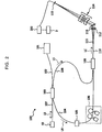
- a fundus observation apparatus 1 includes a retinal camera unit 2, an OCT unit 100, and an arithmetic and control unit 200.
- the retinal camera unit 2 has almost the same optical system as a conventional retinal camera.
- the OCT unit 100 is provided with an optical system for obtaining an OCT image of a fundus.
- the arithmetic and control unit 200 is provided with a computer that executes various arithmetic processes, control processes, and so on.
- the arithmetic and control unit 200 functions as "fundus image analyzing apparatus".
- the retinal camera unit 2 shown in Fig. 1 is provided with an optical system for forming a 2-dimensional image (fundus image) representing the surface morphology of the fundus Ef of an eye E.
- Fundus images include observation images, photographed images, etc.
- the observation image is, for example, a monochromatic moving image formed at a prescribed frame rate using near-infrared light.
- the photographed image may be, for example, a color image captured by flashing visible light, or a monochromatic still image captured by using near-infrared light or visible light as illumination light.
- the retinal camera unit 2 may also be configured to be capable of capturing other types of images such as a fluorescein angiography image, an indocyanine green fluorescent image, and an autofluorescent image.
- the retinal camera unit 2 is an example of "imaging part”.
- a fundus image acquired by the retinal camera unit 2 is an example of "surface image of eye fundus”.
- the retinal camera unit 2 is provided with a chin rest and a forehead placement for supporting the face of the subject. Moreover, the retinal camera unit 2 is provided with the illumination optical system 10 and the imaging optical system 30.
- the illumination optical system 10 irradiates illumination light to the fundus Ef.
- the imaging optical system 30 guides a fundus reflected light of the illumination light to imaging devices (CCD image sensors 35, 38 (sometimes referred to simply as CCD)).
- CCD image sensors 35, 38 sometimes referred to simply as CCD
- the imaging optical system 30 guides signal light input from the OCT unit 100 to the fundus Ef, and guides the signal light returned from the fundus Ef to the OCT unit 100.
- the fundus reflection light of the observation illumination light is refracted by the object lens 22, transmitted through the dichroic mirror 46, passes through the aperture part formed in the center region of the aperture mirror 21, transmitted through a dichroic mirror 55, travels through a focusing lens 31, and reflected by a mirror 32. Furthermore, the fundus reflection light is transmitted through a half-mirror 39A, refracted by reflected by a dichroic mirror 33, and forms an image on the light receiving surface of the CCD image sensor 35 by a condenser lens 34.
- the CCD image sensor 35 detects the fundus reflection light at a preset frame rate, for example.
- An image (observation image) based on the fundus reflection light detected by the CCD image sensor 35 is displayed on a display device 3. It should be noted that when the imaging optical system is focused on the anterior eye part, the observation image of the anterior eye part of the eye E is displayed.
- the imaging light source 15 comprises, for example, a xenon lamp.
- the light (imaging illumination light) output from the imaging light source 15 is irradiated to the fundus Ef via the same route as that of the observation illumination light.
- the fundus reflection light of the imaging illumination light is guided to the dichroic mirror 33 via the same route as that of the observation illumination light, transmitted through the dichroic mirror 33, reflected by a mirror 36, and forms an image on the light receiving surface of the CCD image sensor 38 by a condenser lens 37.
- An image (photographed image) based on the fundus reflection light detected by the CCD image sensor 38 is displayed on the display device 3.
- the display device 3 for displaying the observation image and the display device 3 for displaying the photographed image may be the same or different. Further, when similar photographing is carried out by illuminating the eye E with infrared light, infrared photographed image is displayed. Moreover, LED may be used as the imaging light source.
- An LCD (Liquid Crystal Display) 39 displays a fixation target or a target for measuring visual acuity.
- the fixation target is a visual target for fixating the eye E, and is used when photographing a fundus or performing OCT measurement.
- Part of the light output from the LCD 39 is reflected by the half-mirror 39A, reflected by the mirror 32, passes through the aperture part of the aperture mirror 21, refracted by the object lens 22, and projected onto the fundus Ef.
- the fixation positions of the eye E include the position for acquiring an image centered at the macula of the fundus Ef, the position for acquiring an image centered at the optic papilla, the position for acquiring an image centered at the fundus center located between the macula and the optic papilla, and so on, as in conventional retinal cameras. Further, the display position of the fixation target may be arbitrarily changed.
- the retinal camera unit 2 is provided with an alignment optical system 50 and a focus optical system 60.
- the alignment optical system 50 generates a target (alignment target) for matching the position (alignment) of the device optical system with respect to the eye E.
- the focus optical system 60 generates a target (split target) for matching the focus with respect to the eye Ef.
- Light (alignment light) output from an LED 51 of the alignment optical system 50 passes through diaphragms 52 and 53 and a relay lens 54, is reflected by the dichroic mirror 55, passes through the aperture part of the aperture mirror 21, is transmitted through the dichroic mirror 46, and is projected onto the cornea of the eye E by the object lens 22.
- Cornea reflection light of the alignment light passes through the object lens 22, the dichroic mirror 46 and the aperture part, a part of the cornea reflection light is transmitted through the dichroic mirror 55, passes through the focusing lens 31, reflected by the mirror 32, transmitted through the half-mirror 39A, reflected by the dichroic mirror 33, and projected onto the light receiving surface of the CCD image sensor 35 by the condenser lens 34.
- An image (alignment target) captured by the CCD image sensor 35 is displayed on the display device 3 together with the observation image.
- the user conducts alignment by an operation that is the same as conventional retinal cameras. Further, alignment may be performed in a way in which the arithmetic and control unit 200 analyzes the position of the alignment target and controls the movement of the optical system (automatic alignment function).
- the reflection surface of a reflection rod 67 is positioned at a slanted position on the optical path of the illumination optical system 10.
- Light (focus light) output from an LED 61 of the focus optical system 60 passes through a relay lens 62, is split into two light fluxes by a split target plate 63, passes through a two-hole diaphragm 64, is reflected by a mirror 65, and is reflected after an image is formed once on the reflection surface of the reflection rod 67 by a condenser lens 66.
- the focus light passes through the relay lens 20, is reflected at the aperture mirror 21, is transmitted through the dichroic mirror 46, is refracted by the object lens 22, and is projected onto the fundus Ef.
- the fundus reflection light of the focus light passes through the same route as the cornea reflection light of the alignment light and is detected by the CCD image sensor 35.
- An image (split target) captured by the CCD image sensor 35 is displayed on the display device 3 together with the observation image.
- the arithmetic and control unit 200 analyzes the position of the split target, and moves the focusing lens 31 and the focus optical system 60 for focusing (automatic focusing function). Further, focusing may be performed manually while visually recognizing the split target.
- the optical path length changing part 41 is capable of moving in the direction indicated by the arrow in Fig. 1 to change the length of the optical path for OCT. This change of optical path length may be used for correction of the optical path length in accordance with the axial length of the eye E, and for adjustment of the condition of interference.
- the optical path length changing part 41 is configured to comprise a corner cube and a mechanism for moving the corner cube, for example.
- the galvano scanner 42 changes the travelling direction of light (signal light LS) travelling along the optical path for OCT. Thereby, the fundus Ef is scanned by the signal light LS.
- the galvano scanner 42 is configured to comprise a galvano mirror for scanning with the signal light LS in the x-direction, a galvano mirror for scanning in the y-direction, and a mechanism for independently driving these. Thereby, the signal light LS may be scanned in an arbitrary direction in the xy-plane.
- the OCT unit 100 is provided with an optical system for obtaining an OCT image of the fundus Ef.
- the optical system comprises a similar configuration to a conventional Spectral Domain OCT apparatus. That is to say, this optical system is configured to split low-coherence light into signal light and reference light, superpose the signal light returned form the fundus Ef and the reference light having traveled through a reference optical path to generate interference light, and detect the spectral components of the interference light. This detection result (detection signal) is transmitted to the arithmetic and control unit 200.
- Swept Source OCT apparatus when Swept Source OCT apparatus is used, a swept source is provided instead of a low-coherence light source while an optical member for spectrally decomposing interference light is not provided.
- any known technology in accordance with the type of OCT may be arbitrarily applied for the configuration of the OCT unit 100.
- a light source unit 101 outputs broadband low-coherence light L0.
- the low-coherence light L0 for example, includes near-infrared wavelength band (about 800-900nm) and has a coherence length of about tens of micrometer.
- near-infrared light having wavelength band that is impossible to be detected by human eyes for example, infrared light having the center wavelength of about 1040-1060nm.
- the light source unit 101 is configured to comprise light output device, such as an SLD (super luminescent diode), LED, SOA (Semiconductor Optical Amplifier) and the like.
- SLD super luminescent diode
- LED LED
- SOA semiconductor Optical Amplifier
- the low-coherence light L0 output from the light source unit 101 is guided to a fiber coupler 103 by an optical fiber 102 and split into the signal light LS and the reference light LR.
- the reference light LR is guided to an optical attenuator 105 by an optical fiber 104.
- the optical attenuator 105 received control of the arithmetic and control unit 200 for automatically adjusting light amount (light intensity) of the reference light LR guided to the optical fiber 104.
- the reference light LR having adjusted by the optical attenuator 105 is guided to a polarization controller 106 by the optical fiber 104.
- the polarization controller 106 is a device configured to, for example, apply stress to the loop-form optical fiber 104 from outside to adjust polarization condition of the reference light LR being guided in the optical fiber 104. It should be noted that the configuration of the polarization controller 106 is not limited to this, and arbitrary known technology may be applied.
- the reference light LR having adjusted by the polarization controller 106 is guided to an optical coupler 109.
- the signal light LS generated by the fiber coupler 103 is guided by the optical fiber 107, and converted into a parallel light flux by the collimator lens unit 40. Further, the signal light LS travels through the optical path length changing part 41, the galvano scanner 42, the focusing lens 43, the mirror 44 and the relay lens 45, and reaches the dichroic mirror 46. Further, the signal light LS is reflected by the dichroic mirror 46, refracted by the objective lens 22, and projected to the fundus Ef. The signal light LS is scattered (including reflection) at various depth positions of the fundus Ef. The back-scattered light of the signal light LS from the fundus Ef travels along the same route as the outward way in the opposite direction to the fiber coupler 103, and is reached the fiber coupler 109 through an optical fiber 108.
- the fiber coupler 109 superposes the back-scattered light of the signal light LS and the reference light LR having passed through the optical fiber 104.
- Interference light LC thus generated is guided by an optical fiber 110 and output from an exit end 111.
- the interference light LC is converted into a parallel light flux by a collimator lens 112, spectrally divided (spectrally decomposed) by a diffraction grating 113, converged by a condenser lens 114, and projected onto the light receiving surface of a CCD image sensor 115.
- the diffraction grating 113 shown in Fig. 2 is of transmission type, any other kind of a spectrally decomposing element (such as reflection type) may be used.
- the CCD image sensor 115 is for example a line sensor, and detects the respective spectral components of the spectrally decomposed interference light LC and converts the components into electric charges.
- the CCD image sensor 115 accumulates these electric charges, generates a detection signal, and transmits the detection signal to the arithmetic and control unit 200.
- CMOS Complementary Metal Oxide Semiconductor
- the arithmetic and control unit 200 analyzes the detection signals input from the CCD image sensor 115 to form an OCT image of the fundus Ef. Arithmetic processing for this may be the same as that of a conventional Spectral Domain OCT apparatus.
- the arithmetic and control unit 200 controls each part of the retinal camera unit 2, the display device 3 and the OCT unit 100. For example, the arithmetic and control unit 200 displays an OCT image of the fundus Ef on the display device 3.
- the arithmetic and control unit 200 executes: controls of actions of the observation light source 101, the imaging light source 103 and LED's 51 and 61; control of action of the LCD 39; controls of movements of the focusing lenses 31 and 43; control of movement of the reflection rod 67; control of movement of the focus optical system 60; control of movement of the optical path length changing part 41; control of action of the galvano scanner 42; and so on.
- the arithmetic and control unit 200 executes: control of action of the light source unit 101; control of action of the optical attenuator 105; control of action of the polarization controller 106; control of action of the CCD image sensor 115; and so on.
- the arithmetic and control unit 200 comprises a microprocessor, a RAM, a ROM, a hard disk drive, a communication interface, and so on, as in conventional computers.
- the storage device such as the hard disk drive stores a computer program for controlling the fundus observation apparatus 1.
- the arithmetic and control unit 200 may be provided with various circuit boards such as a circuit board for forming OCT images.
- the arithmetic and control unit 200 may be provided with operation devices (input devices) such as a keyboard, a mouse, etc. and/or a display device such as an LCD etc.
- the retinal camera unit 2, the display device 3, the OCT unit 100, and the arithmetic and control unit 200 may be integrally configured (that is, provided within a single case), or separately configured in two or more cases.
- the control system of the fundus observation apparatus 1 has a configuration centered on a controller 210
- the controller 210 is configured to comprise, for example, the aforementioned microprocessor, RAM, ROM, hard disk drive, and communication interface, etc.
- the controller 210 is provided with a main controller 211 and storage 212.
- the main controller 211 performs the aforementioned various kinds of controls. Specifically, the main controller 211 controls a focus driver 31A, the optical path length changing part 41 and the galvano scanner 42 of the retinal camera unit 2, and further controls the light source unit 101, the optical attenuator 105 and the polarization controller 106 of the OCT unit 100. Further, the main controller 211 executes various display controls as described later.
- the main controller 211 functions as an example of "display controller".
- the focus driver 31A moves the focusing lens 31 in the direction of the optical axis. Thereby, the focus position of the imaging optical system 30 is changed.
- the main controller 211 may control an optical system driver (not shown in diagrams) to three dimensionally move the optical system provided in the retinal camera unit 2. This control is used for alignment and tracking. Tracking is an operation for move the optical system in accordance with eye movement of the eye E. When tracking is applied, alignment and focusing are carried out in advance. Tracking is a function to maintain adequate positional relationship in which alignment and focusing are matched by causing the position of the optical system to follow the eye movement.
- the main controller 211 executes a process of writing data into the storage 212, and a process of reading out data from the storage 212.
- the storage 212 stores various kinds of data.
- the data stored in the storage 212 may include image data of OCT images, image data of fundus images, and eye information, for example.
- the eye information includes information on the eye, such as information on a subject such as a patient ID and a name, identification information on left eye or right eye, and so on. Further, the storage 212 stores various programs and data for operating the fundus observation apparatus 1.
- the image forming part 220 comprises the aforementioned circuit board, for example. It should be noted “image data” and the “image” based on the image data may be identified with each other in the description. Further, a site of the fundus Ef and an image thereof may be identified with each other.
- An image processor 230 executes various image processing and analysis processing on images formed by the image forming part 220.
- the image processor 230 executes various correction processing such as brightness correction, dispersion correction of images, etc.
- the image processor 230 executes various image processing and analysis processing on images obtained by the retinal camera unit 2 (fundus images, anterior eye part images, etc.).
- the image processor 230 executes a rendering process (such as volume rendering and MIP (Maximum Intensity Projection)) on this volume data, and forms image data of a pseudo three-dimensional image taken from a specific view direction. On a display device such as a display 240A, this pseudo three-dimensional image is displayed.
- a rendering process such as volume rendering and MIP (Maximum Intensity Projection)
- stack data of multiple cross sectional images is image data obtained by three-dimensionally arranging multiple cross sectional images obtained along multiple scanning lines, based on the positional relation of the scanning lines. That is to say, stack data is image data obtained by expressing multiple cross sectional images defined by originally individual two-dimensional coordinate systems by a three-dimensional coordinate system (in other words, embedding into a three-dimensional space).
- the image processor 230 may carry out position matching (registration) between a fundus image and an OCT image.
- position matching registration
- a fundus image and an OCT image are acquired in parallel, since both optical systems are coaxial, the fundus image and the OCT image which are acquired (substantially) in parallel can be matched by considering the optical axis of the imaging optical system 30 as a reference. Further, regardless of acquisition timings of a fundus image and an OCT image, it is possible to match an image obtained by projecting the OCT image onto the xy-plane with the fundus image, thereby matching the OCT image and the fundus image.
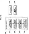
- the image processor 230 comprises a layer region specifying part 231, layer thickness information generating part 232, abnormal region specifying part 233, distribution information generating part 234 and evaluation information generating part 235.
- the layer region specifying part 231, layer thickness information generating part 232 and abnormal region specifying part 233 function as an example of "specifying part”.
- the distribution information generating part 234 functions as an example of "association information generating part”.
- the layer region specifying part 231 is configured to analyze a cross sectional image of the fundus Ef to specify a layer region.
- This cross sectional image may be two-dimensional cross sectional image or three-dimensional image.
- the layer region means an image region in the cross sectional image that corresponds to a stratiform (or membranous) tissue(s) existing in the fundus Ef. It should be noted that there are a retina, choroid and sclera in the fundus Ef.
- the retina may be histologically classified into ten layers, namely, a retinal pigment epithelium layer, visual cell layer, outer limiting membrane, outer granular layer, outer plexiform layer, inner granular layer, inner plexiform layer, ganglion cell layer, nerve fiber layer and inner limiting membrane in this order from the outside.
- the layer region may be an image region corresponding to one or more tissues in the fundus Ef having such structure.
- the layer region specifying part 231 can specify a layer region based on pixel values (brightness value) of the cross sectional image. Further, the layer region specifying part 231 may be configured to specify multiple layer regions based on pixel values of the cross sectional image and select a layer region based on the pixel values, shape etc. thereof. Alternatively, the layer region specifying part 231 may be configured to specify a characteristic site of the fundus Ef (for example, surface of retina, layer region having characteristic pixel values) and specify a layer region based on distance from the characteristic site. In general, specification of a layer region may be carried out by using arbitrary known technology (image processing technology).
- the layer thickness information generating part 232 is configured to analyze the layer region specified by the layer region specifying part 231 to generate layer thickness information related to thickness of this layer region.
- Examples of the layer thickness information include thickness distribution information, symmetric position information, both-eye information. It should be noted that kinds of the layer thickness information are not limited to these. Further, the layer thickness information includes at least one of multiple information including these.
- the thickness distribution information represents distribution of the thickness of the layer region in the cross section of the fundus Ef represented by the cross sectional image of the fundus Ef.
- the layer thickness information generating part 232 obtains thickness of a preset layer (that is, distance along the z-direction between the upper and lower surfaces of this layer) at an arbitrary location in the cross section (that is, location at arbitrary xy-coordinates), and associates the location and the thickness.
- the thickness of the layer may be calculated by counting the number of pixels arranged in the z-direction wherein the pixels compose the layer region, or by calculating distance in the real space defined for the cross sectional image.
- the symmetric position information represents difference or ratio of the thicknesses of the layer region at symmetric positions with respect to central fovea of the fundus Ef.
- the central fovea (that is, the image position corresponding to the central fovea) may be identified as the deepest part or the center of the hollow of macula area depicted in the cross sectional image, may be identified as the center position of the macular area specified based on the pixel values of the fundus image, may be identified from scan position information by the galvano scanner 42, or may be identified based on the positional relationship between fixation position and the axis of optical system (that is, center position of a frame).
- the central fovea may be input manually onto a displayed image of the fundus image or cross sectional image. Further, in the case in which fundus images and/or cross sectional images of the eye E acquired in the past can be referred to, it is possible to identify the location of the central fovea in the current image based on the location of the central fovea identified based on this past image and positional relationship between the past image and the current image. The positional relationship in this process is obtained, for example, by registration between images based on characteristic points (macular area, optic papilla, characteristic blood vessel, branch point of blood vessel, etc.) in the past image and the concerned characteristic points in the current image.
- characteristic points mocular area, optic papilla, characteristic blood vessel, branch point of blood vessel, etc.
- the symmetric positions with respect to central fovea are two positions which are point symmetrical with respect to the central fovea, for example. These two point symmetrical positions are two positions which are away from the central fovea by an equal distance on a line segment passing through the central fovea.
- the distance from the central fovea may be specified as the number of pixels, or may be specified as distance in the real space defined for the xy-plane.
- Other examples of the symmetrical positions may include two positions which are linear symmetrical with respect to a line passing through the central fovea.
- the thicknesses at such two positions are calculated in the same fashion as the thickness distribution information.
- the layer thickness information generating part 232 calculates difference or ratio of two thickness values at a pair of symmetrical positions.
- the difference may be obtained by subtracting one thickness value from the other thickness value, or may be obtained by calculating the absolute value of the difference. It should be noted that the calculated value may be negative in the former case.
- ratio may be calculated by assigning one thickness value to a denominator and the other to a numerator based on a preset orientation.
- the both-eye information is applied to the case in which a cross sectional image is formed for each of right and left eyes of one patient.
- the both-eye information represents difference or ratio of the thicknesses of the layer regions at symmetric positions between the fundus of the right eye and the fundus of the left eye.
- the symmetric positions are positions in which vertical position is defined as upward and downward directions for both eyes and horizontal position is defined as nose and ear directions.
- the symmetric positions are mirror-image positions with respect to a body axis (or center line of a face), that is, symmetrical positions in mirror images.
- the method of calculating the thickness at respective positions and the method of calculating difference or ratio may be same as the abovementioned methods.
- the abnormal region specifying part 233 is configured to specify an abnormal region based on the layer thickness information generated by the layer thickness information generating part 232.
- the abnormal region may include not only a region judged as a site in which abnormality of the fundus Ef has been actually caused by a disease but also a region presumed to be a site in which abnormality may have been caused.
- an evaluation target is the thickness of a layer region (that is, becoming thinner or becoming thicker). Evaluation of the thickness of a layer region may be carried out, for example, by comparing with a normal range that is set based on a statistic (mean value, standard deviation, etc.) of thicknesses acquired from OCT measurements of multiple normal eyes. This normal range may be constant over a whole measurement target region, or may be set for each of multiple regions obtained from dividing the measurement target region. Further, the normal region may be set individually for respective layer regions.
- the abnormality to be judged is not limited to structural abnormalities, and it may be functional abnormalities such as blood flow or optical abnormalities.
- Type of OCT images to which analysis processing is applied is determined according to type of such abnormalities. For example, ordinary OCT images that depict morphology of the fundus Ef is applied when structural abnormality is judged, OCT images acquired from functional measurement (Doppler OCT etc.) is applied when functional abnormality is judged, and OCT images acquired from optical characteristic measurement (polarization OCT etc.) is applied when optical abnormality is judged.
- processing for specifying an abnormal region may include processes of: calculating the size of a region that is provisionally specified to be abnormal; and judging this (provisional) abnormal region as a normal region when the size thereof is equal to or less than a preset threshold.
- This size area, volume, etc.
- the threshold can be obtained in an arbitrary manner; for example, the size of noises may be calculated by actually carrying out OCT measurement, may be calculated theoretically, or may be calculated from clinical data of sizes of abnormalities.
- the fundus observation apparatus 1 sets fixation position for macula and carries out radial scan described below.
- This radial scan comprises a preset number of linear scans (line scans) that are centered at central fovea, for example. These linear scans are arranged at intervals of an equal angle.
- the number of linear scans is arbitrary set; larger number (for example, 180 linear scans at 1 degree intervals) is set when intending to improving precision of examination, and smaller number is set when intending to shorten examination time.
- a scanning mode that is applicable in the present embodiment is not limited to the radial scan, and it is possible to apply other scanning modes such as three-dimensional scan.
- the distribution information generating part 234 analyzes a cross sectional image corresponding to each of the line scans to calculate the distance between the central fovea and the abnormal region in the concerned cross section.
- This cross section is a plane that is along the locus of a line scan and spreads in the z-direction. Further, processing of calculating distance comprises specification of an abnormal region in the concerned cross section. More specifically, the distribution information generating part 234 identifies xy-coodinates common between the abnormal region specified by the abnormal region specifying part 233 and the concerned cross section, and selects, from among the xy-coodinates identified, xy-coodinates that is closest to the xy-coordinates of the central fovea.
- the distance between the selected xy-coodinates and the xy-coordinates of the central fovea is regarded as the distance between the central fovea and the abnormal region in the concerned cross section. It should be noted that there is no abnormal region in the concerned cross section when there is no common xy-coordinates. Further, this distance may be expressed as the number of pixels or distance in the real space in the same way as calculation of thickness of a layer region described above.
- the distribution information generating part 234 carries out the above calculation processing on each of the cross sectional images. Thereby, distribution information that represents distribution of distances in multiple directions corresponding to the multiple cross sections.
- the multiple directions corresponding to the multiple cross sections may be direction defined by setting the central fovea as a reference. In the present embodiment, the directions are defined such that angle 0 degree is set to a preset direction (x-axis direction, y-axis direction, etc.) and the value of angle increases in a preset rotation direction (clockwise direction or counterclockwise direction) in the xy-coordinate system with the origin located at central fovea.
- the distribution information is generated by associating the distance between central fovea and an abnormal region with each direction (angle etc.) defined in such a way.
- the distribution information is an example of "association information”.
- the distribution information generating part 234 functions as an example of "association information generating part”.
- Fig. 5 illustrates an example of the distribution information.
- the horizontal axis shows direction in which central fovea is set to be the origin, and the vertical axis shows distance from the central fovea.
- "T", "S", “N” and “I” respectively shows temporal direction, superior direction, nasal direction and inferior direction, as conventionally used in ophthalmology.
- the angle between two neighboring directions is 90 a right angle.
- an OCT measurement region corresponding to this graph information is a disc-shaped region of area that extends 3mm in the respective directions from central fovea.
- Such OCT measurement is realized by radial scan that is a combination of multiple line scans of length 6mm.
- data included in the disk-shaped region may be extracted from data acquired by carrying out three-dimensional scan of 6mm x 6mm area centered at central fovea. Further, concentric scan may be applied.
- the graph information is generated by the evaluation information generating part 235, for example. It should be noted that a template of a coordinate system for generating graph information is stored in the storage 212 etc. in advance. Graph information may be displayed on the display 240A by the main controller 211. In this case, the main controller 211 functions as "display controller". Graph information is an example of evaluation information described below.
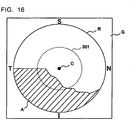
- Fig. 6 illustrates distribution of abnormal regions that are the base of the graph information illustrated in Fig. 5 .
- information that expresses the distribution of the abnormal regions is formed based on distribution information and fundus image.
- the background of the abnormal region distribution image is a fundus image G photographed by the retinal camera unit 2.
- the fundus image G is photographed with fixation position for macula as described above, and central fovea C is depicted at almost center position of the frame.
- the fundus image G may be an image obtained by trimming a wide-angle image, or may be an image photographed with an angle of view corresponding to the size of the scanning region R (disk-shaped region of a diameter 6mm in this case).
- a shaded region shown by symbol A indicates an abnormal region.
- the abnormal region A is displayed in a different aspect from other regions (including normal regions). As an example of this, it is possible to assign a preset color to the partial region of the fundus image G corresponding to the abnormal region A, or to display the contour of this partial region.
- the abnormal region distribution image is generated by the evaluation information generating part 235, for example.
- the abnormal region distribution image may be displayed on the display 240A by the main controller 211.
- the main controller 211 functions as "display controller”.
- the abnormal region distribution image is an example of evaluation information described below.
- the evaluation information generating part 235 is configured to generate evaluation information used for diagnosis of the eye E based on the distribution information generated by the distribution information generating part 234. Items recorded as evaluation information is appropriately determined according to purpose of diagnosis.
- the evaluation information is displayed in a preset form by the main controller 211. Examples of the display modes include a method of displaying the evaluation information as a numerical value, a method of displaying the evaluation information as an image, and a method of displaying the evaluation information using graph information, and so on. Examples of evaluation information and display mode thereof are described below.
- a first example of evaluation information includes information (nearest direction information) that expresses the direction in which an abnormal region is located nearest to central fovea.
- the evaluation information generating part 235 firstly compares the magnitudes of distances included in the distribution information generated by the distribution information generating part 234 to specify the minimum. Next, the evaluation information generating part 235 specifies the direction (nearest direction) corresponding to this minimum by referring to the distribution information. Then, the evaluation information generating part 235 generates nearest direction information based on the nearest direction specified.
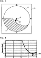
- Figs. 7 and 8 illustrate examples of the nearest direction information.
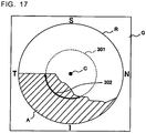
- an arrow 201 that connects the central fovea C and the location on the abnormal region closest to the central fovea C is displayed, as evaluation information, on the abnormal region distribution image illustrated in Fig. 6 .
- the direction shown by the arrow 201 indicates the nearest direction.
- an arrow 202 that indicates the position showing the nearest direction on the horizontal axis and the position on the graph nearest to the horizontal axis is displayed, as evaluation information, on the graph information illustrated in Fig. 5 .
- the numerical value (that is, angle) indicating the nearest direction may be displayed together with the arrows 201 or 202.
- a second example of evaluation information is information (near direction information) that expresses direction in which the distance between abnormal region and central fovea is equal to or less than a preset threshold.
- the evaluation information generating part 235 firstly compares respective distances included in the distribution information with the preset threshold to select distances that are equal to or less than this threshold.
- This threshold may be a default setting, or may be arbitrarily set by a user.
- the evaluation information generating part 235 specifies the direction corresponding to each of the selected directions by referring to the distribution information. Then, the evaluation information generating part 235 generates near direction information based on the direction specified.
- Examples of the near direction information include the following:
- the ratio information in the example (1) is explained.
- the ratio information expresses the ratio of directions in which the distance between a central fovea and abnormal region is equal to or less than a threshold.
- the ratio information is not limited to a ratio of such directions to the whole, and may be the number (or angles) of such directions. This is because the whole number and angle are determined in advance.
- the evaluation information generating part 235 When ratio information is generated, the evaluation information generating part 235 firstly compares respective distances included in the distribution information with a threshold to specify distances that are equal to or less than this threshold. Next, the evaluation information generating part 235 specifies the direction corresponding to each of the specified directions by referring to the distribution information. Then, the evaluation information generating part 235 generates ratio information based on all the directions included in the distribution information and the specified direction. In this processing, a quotient or ratio may be calculated based on the number of the specified directions and the number of all the directions, or the number of the specified directions may be counted, for example.
- Figs. 9 and 10 illustrate examples of displaying the ratio information.
- ratio information 203 consisting of an arrow indicating the range of the specified directions is presented on the abnormal region distribution image illustrated in Fig. 6 .
- ratio information 204 consisting of an arrow indicating the range of the specified directions on the horizontal axis of the distribution information illustrated in Fig. 5 is presented.
- threshold SH that is applied for obtaining this ratio information 204 is presented.
- illustration is omitted, it is possible to display, as ratio information, a numerical value indicating the number of the specified directions, the angles thereof, the above quotient or ratio, or the like.
- the size information in the example (2) expresses the size of normal region located between an abnormal region and central fovea in the direction in which the distance between a central fovea and abnormal region is equal to or less than a threshold.
- This normal region is a region indicated by symbol 205 in Fig. 11 .
- Fig. 11 is an example of a mode of displaying the size region.
- the evaluation information generating part 235 When size information is generated, the evaluation information generating part 235 firstly compares respective distances included in the distribution information with a threshold to specify distances that are equal to or less than this threshold. Next, the evaluation information generating part 235 specifies the direction corresponding to each of the specified directions by referring to the distribution information. Then, the evaluation information generating part 235 identifies the region between the central fovea and abnormal region for each of the specified directions. The identified region corresponds to a normal region. The total sum of the normal regions thus obtained for the respective directions is regarded as the size information.
- Size information may be the total sum of the values of areas of such normal regions, may be the ratio between the area of normal regions and the area of abnormal regions in all the specified directions, or may be the ratio between the whole area of all the specified directions and the area of normal regions. Further, since the whole area is the sum of abnormal regions and normal regions, size information may be the ratio between whole area of all the specified directions and the area of abnormal regions. Moreover, volume may be used instead of area. The volume may be a volume of a layer region used for generating layer thickness information, or may be a volume of other layer regions. Modes of displaying size information are not limited to the way illustrated in Fig. 11 , and may be presentation of any of the above calculation results by a numerical value.
- This statistic is a value statistically calculated from the thickness of a layer region in a normal region specified in the same way as the example (2).
- This layer region is arbitrary as in example (2).
- Examples of this statistic include a mean value, maximum value, minimum value, variance, standard deviation, median, etc.
- this statistic is not necessarily a single value, and may include two or more values. For example, two or more or the multiple statistics exemplified above may be included, or a certain number of values from the largest one (and/or the smallest one) in order may be included.
- the main controller 211 displays the statistic(s) calculated by the evaluation information generating part 235 on the display 240A.
- multiple directions included in distribution information are divided into two or more groups, and evaluation information is generated for each of the groups.
- Mode of dividing multiple directions is set in advance.
- the mode of division may be a default setting, or may be arbitrarily set by a user. Further, multiple modes of division selectable by a user may be provided in advance.
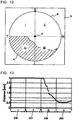
- the scanning region R is divided into four areas (quadrants). It should be noted that mode of dividing the scanning region R (that is, mode of dividing the multiple directions) is not limited to this, and the number of partitions and region (directions) to be divided are arbitrary.
- the statistic of distance in the example (1) is explained.
- the distance between an abnormal region and central fovea in the respective directions is calculated as described above.
- the evaluation information generating part 235 calculates the statistic of distance in direction included in the concerned group. Examples of this statistic include a mean value, maximum value, minimum value, variance, standard deviation, median, etc. Further, this statistic is not necessarily a single value, and may include two or more values.
- the main controller 211 displays the calculated statistic(s) on the display 240A.
- a statistic of distance is obtained for each of four groups i to iv.
- this direction may be presented.
- such direction is indicated by a line segment extending from the central fovea in this direction.
- Fig. 13 it is possible to present multiple groups by dividing the horizontal axis of distribution information into the multiple groups (four groups 206 to 209 in this case).
- a maximum value and/or minimum value by a line segment extending, in parallel with the vertical axis, from the position on the horizontal axis corresponding to the concerned direction, for example.
- the size information in the example (2) is explained. This size information is calculated as in "second example of evaluation information" for each of the multiple groups.
- the main controller 211 displays the calculated size information on the display 240A.
- the statistic of thickness in the example (3) is explained. This statistic is calculated as in "second example of evaluation information" for each of the multiple groups.
- the main controller 211 displays the calculated statistic on the display 240A.
- the ratio information in the example (4) expresses the ratio of an abnormal region in the image region of each of the groups.
- this ratio information is calculated by, for each of the groups, dividing the area of the image region that is judged to be an abnormal region by the area of the image region of this group. For example, with respect to the quadrant (group) iii in the example illustrated in Fig. 12 , calculation of dividing the area of the shaded region in the quadrant iii by the area of the quadrant iii is carried out.
- the main controller 211 displays any of ratio information calculated as above on the display 240A.
- the size information in the example (5) expresses the size of an abnormal region. Processing of calculating this size information may be carried out as in the case of the size information of a normal region in the example (2).
- the main controller 211 displays the calculated size information of the abnormal region on the display 240A.
- the statistic in the example (6) is obtained by statistically processing the thickness of an arbitrary layer region in an abnormal region for each of the groups. Examples of this statistic include a mean value, maximum value, minimum value, variance, standard deviation, median, etc. Further, this statistic is not necessarily a single value, and may include two or more values.
- the main controller 211 displays the calculated statistic(s) on the display 240A.
- the image processor 230 that functions as above comprises, for example, the aforementioned microprocessor, RAM, ROM, hard disk drive, circuit board, and so on.
- a computer program that causes the microprocessor to perform the above functions is stored in the storage device such as the hard disk drive in advance.
- a user interface 240 comprises the display 240A and the operation part 240B.
- the display 240A is configured to include a display device of the aforementioned arithmetic and control unit 200 and/or the display device 3.
- the operation part 240B is configured to include an operation device of the aforementioned arithmetic and control unit 200.
- the operation part 240B may also comprise various kinds of buttons, keys, etc. that are provided with the case of the fundus observation apparatus 1 or outside thereof.
- the display 240A may also include various display devices such as a touch panel monitor etc. provided with the case of the retinal camera unit 2.
- the display 240A and the operation part 240B do not need to be configured as separate components.
- the operation part 240B is configured to include a touch panel monitor and a computer program.
- a content of operation to the operation part 240B is input into the controller 210 as an electrical signal. Further, operations and/or information input may be carried out by using a graphical user interface (GUI) displayed on the display 240A and the operation part 240B.
- GUI graphical user interface
- the scanning modes of the signal light LS by the fundus observation apparatus 1 may include, for example, horizontal scan, vertical scan, cruciform scan, radial scan, circular scan, concentric scan, helical scan, etc. These scanning modes are selectively used as necessary taking into account an observation site of a fundus, an analysis target (retinal thickness etc.), time required for scanning, the density of scanning, and so on.
- the horizontal scan is one for scanning the signal light LS in the horizontal direction (x-direction).
- the horizontal scan includes a mode of scanning the signal light LS along multiple scanning lines extending in the horizontal direction arranged in the vertical direction (y-direction).
- the interval of scanning lines may be arbitrarily set. Further, by setting the interval between adjacent scanning lines to be sufficiently narrow, it is possible to form the aforementioned three-dimensional image (three-dimensional scan).
- the vertical scan is performed in a similar manner.
- the cruciform scan is one for scanning the signal light LS along a cross-shape trajectory consisting of two linear trajectories (line trajectories) orthogonal to each other.
- the radial scan is one for scanning the signal light LS along a radial trajectory consisting of multiple line trajectories arranged at predetermined angles. It should be noted that the cruciform scan is an example of the radial scan.
- the circular scan is one for scanning the signal light LS along a circular trajectory.
- the concentric scan is one for scanning the signal light LS along multiple circular trajectories arranged concentrically around a predetermined center position.
- the circular scan is an example of the concentric scan.
- the helical scan is one for scanning the signal light LS along a helical trajectory while making the turning radius gradually smaller (or greater).
- the galvano scanner 42 is configured to scan the signal light LS in the directions orthogonal to each other, the galvano scanner 42 is capable of scanning the signal light LS in the x-direction and the y-direction independently. Moreover, it is possible to scan the signal light LS along an arbitrary trajectory on the xy-plane by simultaneously controlling the directions of two galvano mirrors included in the galvano mirror 42. Thus, various kinds of scanning modes as described above may be realized.
- a region on the fundus Ef subjected to scanning by the signal light LS as above, that is, a region on the fundus Ef subjected to OCT measurement, is referred to as a scanning region.
- a scanning region for the three-dimensional scan is a rectangular-shaped region in which multiple horizontal scans are arranged.
- a scanning region for the concentric circular scan is a disc-shaped region surrounded by the trajectories of a circular scan of a maximum diameter.
- the scanning region for the radial scan is a disc-shaped (or polygonal-shaped) region linking end positions of the scanning lines.
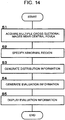
- FIG. 14 illustrates an example of the operation of the fundus observation apparatus 1. It is assumed that alignment and focusing have already done and a fixation target for macula is being presented to the eye. It should be noted that the flow of processes is simply described below since each process has been described in detail.
- the main controller 211 controls the galvano scanner 42 etc. to scan the vicinity of the central fovea of the fundus Ef with the signal light LS. This scanning is radial scan centered at the central fovea, for example.
- the image forming part 220 forms multiple cross sectional images corresponding to this scanning mode.
- the image processor 230 specifies an abnormal region based on the multiple cross sectional images acquired in the step 1.
- This processing includes processing of specifying a layer region by the layer region specifying part 231, processing of generating layer thickness information by the layer thickness information generating part 232, and processing of specifying an abnormal region by the abnormal region specifying part 233.
- the distribution information generating part 234 generates distribution information based on the abnormal region specified in the step 2.
- This processing includes processing of calculating the distance between the central fovea and the abnormal region for each of the cross sectional images, and processing of associating the direction of the respective cross section with the distance. Thereby, distribution information as shown in Fig. 5 is obtained.
- the evaluation information generating part 235 generates evaluation information based on the distribution information generated in the step 3.
- the evaluation information generated here is at least one of the aforementioned examples. It may be configured that a kind(s) of evaluation information to be generated is designated in advance.
- the main controller 211 displays the evaluation information generated in the step 4 on the display 240A. Display modes thereof are described above. It may be configured to generate multiple kinds of evaluation information in the step 4 and selectively display evaluation information of a kind(s) designated by using the operation part 240B.
- the fundus observation apparatus 1 comprises the optical system, image forming part 220, layer region specifying part 231, layer thickness information generating part 232, abnormal region specifying part 233, distribution information generating part 234 and evaluation information generating part 235.
- the optical system divides light from the light source unit 101 into the signal light LS and reference light LR, generates the interference light LC by superposing the signal light LS having traveled by way of the fundus Ef and the reference light LR having traveled by way of the reference optical path, and detects the interference light LC.
- the image forming part forms a cross sectional image of the fundus Ef based on detection results of the interference light LC.
- the layer region specifying part 231, layer thickness information generating part 232 and abnormal region specifying part 233 analyze the cross sectional image to specify an abnormal region located in the vicinity of central fovea of the fundus Ef.
- the distribution information generating part 234 calculates the distance between the central fovea and the abnormal region, and generates association information in which the direction of the abnormal region relative to the central fovea and the distance are associated with each other.
- the evaluation information generating part 235 generates evaluation information for evaluating the state of the fundus Ef based on the association information.
- the image forming part 220 forms multiple cross sectional images of multiple cross sections located in the vicinity of the central fovea of the fundus Ef based on detection results of the interference light LC.
- the distribution information generating part 234 calculates, for each of the multiple cross sectional images, the distance between the central fovea and the abnormal region in the concerned cross section, and generates, as the association information, distribution information that represents distribution of distances in multiple directions corresponding to the multiple cross sections, for example.
- the evaluation information generating part 235 generates the evaluation information based on the distribution information.
- the fundus observation apparatus 1 it is possible to obtain evaluation information based on distribution state of abnormal regions in the vicinity of the central fovea.
- objective data for center management may be provided while considering reduction of examination time.
- the fundus image analyzing apparatus may be realized as part of a fundus observation apparatus such as the arithmetic and control unit 200 in the above embodiments. Alternatively, it is possible to apply a fundus image analyzing apparatus that does not comprise a function for OCT measurement and/or fundus photography.
- the first example of fundus image analyzing apparatus comprises a receiving part, specifying part, association information generating part and evaluation information generating part.
- the receiving part is configured to receive a cross sectional image of an eye fundus. Examples of the receiving part include a communication interface and a drive apparatus.
- the specifying part is configured to analyze the cross sectional image to specify an abnormal region located in the vicinity of central fovea of the eye fundus.
- the association information generating part has the same function as that in the first embodiment, for example, and is configured to calculate the distance between the central fovea and the abnormal region and generate association information in which the direction of the abnormal region relative to the central fovea and the distance are associated with each other.
- the evaluation information generating part has the same function as that in the first embodiment, for example, and is configured to generate evaluation information for evaluating the state of the eye fundus based on the association information.
- the second example of fundus image analyzing apparatus comprises a receiving part, specifying part, and evaluation information generating part.
- the receiving part is configured to receive a cross sectional image of a cross section along a circle around central fovea of an eye fundus.
- the receiving part may be the same device as the first example.
- the specifying part is configured to analyze the cross sectional image to specify an abnormal region and/or normal region in the cross section along the circle as in the second embodiment.
- the evaluation information generating part is configured to generate evaluation information for evaluating the state of the eye fundus including at least one of: the length of the abnormal region and/or normal region; ratio of the length of the abnormal region and/or normal region to the length of the circle; and the difference or ratio between the length of the abnormal region and the length of the normal region as in the second embodiment.
- the fundus image analyzing apparatus thus configured, it is possible to obtain evaluation information based on distribution state of abnormal regions in the vicinity of the central fovea. By carrying out such examination instead of visual field test, objective data for center management may be provided while considering reduction of examination time.
- the optical path length difference between the optical path of the signal light LS and the optical path of the reference light LR is changed by varying the position of the optical path length changing part 41; however, a method for changing the optical path length difference is not limited to this.
- the optical path length difference may be changed by moving the retinal camera unit 2 and/or the OCT unit 100 with respect to the eye E to change the optical path length of the signal light LS.
- Computer programs for implementing the above embodiments can be stored in any kind of recording medium that can be read by a computer.
- recording media for example, an optical disk, a semiconductor memory, a magnetooptic disk (CD-ROM, DVD-RAM, DVD-ROM, MO, and so on), and a magnetic storage (a hard disk, a floppy disk (TM), ZIP, and so on) can be used.
Landscapes
- Health & Medical Sciences (AREA)
- Life Sciences & Earth Sciences (AREA)
- Engineering & Computer Science (AREA)
- General Health & Medical Sciences (AREA)
- Medical Informatics (AREA)
- Physics & Mathematics (AREA)
- Biophysics (AREA)
- Public Health (AREA)
- Biomedical Technology (AREA)
- Heart & Thoracic Surgery (AREA)
- Veterinary Medicine (AREA)
- Molecular Biology (AREA)
- Surgery (AREA)
- Animal Behavior & Ethology (AREA)
- Ophthalmology & Optometry (AREA)
- Nuclear Medicine, Radiotherapy & Molecular Imaging (AREA)
- Radiology & Medical Imaging (AREA)
- Quality & Reliability (AREA)
- Computer Vision & Pattern Recognition (AREA)
- General Physics & Mathematics (AREA)
- Theoretical Computer Science (AREA)
- Eye Examination Apparatus (AREA)
- Signal Processing (AREA)
Claims (14)
- Fundusbeobachtungsvorrichtung, umfassend:ein optisches System, das konfiguriert ist, Licht von einer Lichtquelle in Signallicht und Bezugslicht zu teilen, Interferenzlicht zu erzeugen, indem das Signallicht, das sich über einen Augenfundus bewegt hat, und das Bezugslicht, das sich über einen optischen Referenzweg bewegt hat, überlagert werden, und das Interferenzlicht zu detektieren;einen Bilderzeugungsteil (220), der konfiguriert ist, ein Querschnittsbild des Augenfundus basierend auf Detektionsergebnissen des Interferenzlichts zu erzeugen;einen Spezifizierungsteil (231-233), der konfiguriert ist, das Querschnittsbild zu analysieren, um eine anormale Region in der Nähe der zentralen Fovea des Augenfundus zu spezifizieren;einen Zuordnungsinformationserzeugungsteil (234), der konfiguriert ist, den Abstand zwischen der zentralen Fovea und der anormalen Region zu berechnen und Zuordnungsinformationen zu erzeugen, in denen die Richtung der anormalen Region relativ zur zentralen Fovea und der Abstand einander zugeordnet sind; undeinen Bewertungsinformationserzeugungsteil (235), der konfiguriert ist, Bewertungsinformationen zur Bewertung des Zustands des Augenfundus basierend auf den Zuordnungsinformationen zu erzeugen, wobeider Bilderzeugungsteil (220) basierend auf den Detektionsergebnissen des Interferenzlichts mehrere Querschnittsbilder von mehreren Querschnitten, die sich in der Nähe der zentralen Fovea des Augenfundus befinden, erzeugt undder Zuordnungsinformationserzeugungsteil (234) einen Verteilungsinformationserzeugungsteil umfasst, der konfiguriert ist, für jedes der mehrfachen Querschnittsbilder den Abstand zwischen der zentralen Fovea und der anormalen Region in dem betreffenden Querschnitt zu berechnen und als die Zuordnungsinformationen Verteilungsinformationen zu erzeugen, welche die Verteilung von Abständen in mehreren Richtungen entsprechend den mehrfachen Querschnitten darstellen,dadurch gekennzeichnet, dassder Bewertungsinformationserzeugungsteil (235) den Minimalwert aus den in den Verteilungsinformationen beinhalteten Abständen spezifiziert, die Richtung aus den mehreren Richtungen spezifiziert, die dem Minimalwert entspricht, und die Bewertungsinformationen basierend auf der spezifizierten Richtung erzeugt.
- Fundusbeobachtungsvorrichtung, umfassend:ein optisches System, das konfiguriert ist, Licht von einer Lichtquelle in Signallicht und Bezugslicht zu teilen, Interferenzlicht zu erzeugen, indem das Signallicht, das sich über einen Augenfundus bewegt hat, und das Bezugslicht, das sich über einen optischen Referenzweg bewegt hat, überlagert werden, und das Interferenzlicht zu detektieren;einen Bilderzeugungsteil (220), der konfiguriert ist, ein Querschnittsbild des Augenfundus basierend auf Detektionsergebnissen des Interferenzlichts zu erzeugen;einen Spezifizierungsteil (231-233), der konfiguriert ist, das Querschnittsbild zu analysieren, um eine anormale Region in der Nähe der zentralen Fovea des Augenfundus zu spezifizieren;einen Zuordnungsinformationserzeugungsteil (234), der konfiguriert ist, den Abstand zwischen der zentralen Fovea und der anormalen Region zu berechnen und Zuordnungsinformationen zu erzeugen, in denen die Richtung der anormalen Region relativ zur zentralen Fovea und der Abstand einander zugeordnet sind; undeinen Bewertungsinformationserzeugungsteil (235), der konfiguriert ist, Bewertungsinformationen zur Bewertung des Zustands des Augenfundus basierend auf den Zuordnungsinformationen zu erzeugen, wobeider Bilderzeugungsteil (220) basierend auf den Detektionsergebnissen des Interferenzlichts mehrere Querschnittsbilder von mehreren Querschnitten, die sich in der Nähe der zentralen Fovea des Augenfundus befinden, erzeugt undder Zuordnungsinformationserzeugungsteil (234) einen Verteilungsinformationserzeugungsteil umfasst, der konfiguriert ist, für jedes der mehrfachen Querschnittsbilder den Abstand zwischen der zentralen Fovea und der anormalen Region in dem betreffenden Querschnitt zu berechnen und als die Zuordnungsinformationen Verteilungsinformationen zu erzeugen, welche die Verteilung von Abständen in mehreren Richtungen entsprechend den mehreren Querschnitten darstellen,dadurch gekennzeichnet, dassder Bewertungsinformationserzeugungsteil (235) den Abstand aus den in den Verteilungsinformationen beinhalteten Abständen spezifiziert, der gleich oder kleiner als ein vorgegebener Schwellenwert ist, die Richtung aus den mehreren Richtungen spezifiziert, die dem spezifizierten Abstand entspricht, und die Bewertungsinformationen basierend auf der spezifizierten Richtung erzeugt.
- Fundusbeobachtungsvorrichtung nach Anspruch 2, wobei der Bewertungsinformationserzeugungsteil (235) als die Bewertungsinformationen das Verhältnis der spezifizierten Richtungen zu den mehreren Richtungen berechnet.
- Fundusbeobachtungsvorrichtung nach Anspruch 2, wobei der Bewertungsinformationserzeugungsteil (235) als die Bewertungsinformationen Größeninformationen berechnet, welche die Größe einer normalen Region darstellen, die sich zwischen der anormalen Region und der zentralen Fovea in der angegebenen Richtung befindet.
- Fundusbeobachtungsvorrichtung nach Anspruch 4, ferner umfassend:einen Abbildungsteil (2), der konfiguriert ist, die Oberfläche des Augenfundus abzubilden;eine Anzeige (240A); undeine Anzeigesteuerung (211), die konfiguriert ist, ein Oberflächenbild des Augenfundus, das durch den Abbildungsteil (2) erlangt wurde, auf der Anzeige (240A) anzuzeigen und eine Teilregion in dem Oberflächenbild, die der normalen Region entspricht, in einem von den anderen Regionen unterschiedlichen Aspekt anzuzeigen.
- Fundusbeobachtungsvorrichtung nach Anspruch 2, wobei der Bewertungsinformationserzeugungsteil (235) als die Bewertungsinformationen eine Statistik der Dicke einer Schichtregion in einer normalen Region berechnet, die sich zwischen der anormalen Region und der zentralen Fovea in der angegebenen Richtung befindet.
- Fundusbeobachtungsvorrichtung, umfassend:ein optisches System, das konfiguriert ist, Licht von einer Lichtquelle in Signallicht und Bezugslicht zu teilen, Interferenzlicht zu erzeugen, indem das Signallicht, das sich über einen Augenfundus bewegt hat, und das Bezugslicht, das sich über einen optischen Referenzweg bewegt hat, überlagert werden, und das Interferenzlicht zu detektieren;einen Bilderzeugungsteil (220), der konfiguriert ist, ein Querschnittsbild des Augenfundus basierend auf Detektionsergebnissen des Interferenzlichts zu erzeugen;einen Spezifizierungsteil (231-233), der konfiguriert ist, das Querschnittsbild zu analysieren, um eine anormale Region in der Nähe der zentralen Fovea des Augenfundus zu spezifizieren;einen Zuordnungsinformationserzeugungsteil (234), der konfiguriert ist, den Abstand zwischen der zentralen Fovea und der anormalen Region zu berechnen und Zuordnungsinformationen zu erzeugen, in denen die Richtung der anormalen Region relativ zur zentralen Fovea und der Abstand einander zugeordnet sind; undeinen Bewertungsinformationserzeugungsteil (235), der konfiguriert ist, Bewertungsinformationen zur Bewertung des Zustands des Augenfundus basierend auf den Zuordnungsinformationen zu erzeugen, wobeider Bilderzeugungsteil (220) mehrere Querschnittsbilder mehrerer Querschnitte, die sich in der Nähe der zentralen Fovea des Augenfundus befinden, basierend auf Detektionsergebnissen des Interferenzlichts bildet, undder Zuordnungsinformationserzeugungsteil (234) einen Verteilungsinformationserzeugungsteil umfasst, der konfiguriert ist, für jedes der mehreren Querschnittsbilder den Abstand zwischen der zentralen Fovea und der anormalen Region in dem betreffenden Querschnitt zu berechnen und als die Zuordnungsinformationen Verteilungsinformationen zu erzeugen, welche die Verteilung von Abständen in mehreren Richtungen entsprechend den mehreren Querschnitten darstellen,dadurch gekennzeichnet, dassder Bewertungsinformationserzeugungsteil (235) die mehreren Richtungen in zwei oder mehr Gruppen aufteilt und die Bewertungsinformationen für jede der zwei oder mehr Gruppen erzeugt.
- Fundusbeobachtungsvorrichtung nach Anspruch 7, wobei der Bewertungsinformationserzeugungsteil (235) als die Bewertungsinformationen eine Statistik des Abstands zwischen der anormalen Region und der zentralen Fovea für jede der zwei oder mehr Gruppen berechnet.
- Fundusbeobachtungsvorrichtung nach Anspruch 7, wobei der Bewertungsinformationserzeugungsteil (235) als die Bewertungsinformationen Größeninformationen, welche die Größe einer normalen Region darstellen, die sich zwischen der anormalen Region und der zentralen Fovea befindet, für jede der zwei oder mehr Gruppen berechnet.
- Fundusbeobachtungsvorrichtung nach Anspruch 9, ferner umfassend:einen Abbildungsteil (2), der konfiguriert ist, die Oberfläche des Augenfundus abzubilden;eine Anzeige (240A); undeine Anzeigesteuerung (211), die konfiguriert ist, ein Oberflächenbild des Augenfundus, das durch den Abbildungsteil (2) erlangt wurde, auf der Anzeige (240A) anzuzeigen und eine Teilregion in dem Oberflächenbild, die der normalen Region entspricht, in einem von den anderen Regionen unterschiedlichen Aspekt anzuzeigen.
- Fundusbeobachtungsvorrichtung nach Anspruch 7, wobei der Bewertungsinformationserzeugungsteil (235) als die Bewertungsinformationen eine Statistik der Dicke einer Schichtregion in einer normalen Region, die sich zwischen der anormalen Region und der zentralen Fovea befindet, für jede der zwei oder mehr Gruppen berechnet.
- Fundusbeobachtungsvorrichtung nach Anspruch 7, wobei für jede der zwei oder mehr Gruppen der Bewertungsinformationserzeugungsteil (235) als die Bewertungsinformationen das Verhältnis der anormalen Region zu der Bildregion berechnet, die zu der betreffenden Gruppe gehört.
- Fundusbeobachtungsvorrichtung nach Anspruch 7, wobei der Bewertungsinformationserzeugungsteil (235) als die Bewertungsinformationen Größeninformationen, welche die Größe der anormalen Region darstellen, für jede der zwei oder mehr Gruppen berechnet.
- Fundusbeobachtungsvorrichtung nach Anspruch 7, wobei der Bewertungsinformationserzeugungsteil (235) als die Bewertungsinformationen eine Statistik der Dicke einer Schichtregion in der anormalen Region für jede der zwei oder mehr Gruppen berechnet.
Applications Claiming Priority (2)
| Application Number | Priority Date | Filing Date | Title |
|---|---|---|---|
| JP2012042920A JP5936254B2 (ja) | 2012-02-29 | 2012-02-29 | 眼底観察装置及び眼底画像解析装置 |
| PCT/JP2013/051098 WO2013128975A1 (ja) | 2012-02-29 | 2013-01-21 | 眼底観察装置及び眼底画像解析装置 |
Publications (3)
| Publication Number | Publication Date |
|---|---|
| EP2821007A1 EP2821007A1 (de) | 2015-01-07 |
| EP2821007A4 EP2821007A4 (de) | 2016-04-13 |
| EP2821007B1 true EP2821007B1 (de) | 2020-04-22 |
Family
ID=49082181
Family Applications (1)
| Application Number | Title | Priority Date | Filing Date |
|---|---|---|---|
| EP13755334.3A Active EP2821007B1 (de) | 2012-02-29 | 2013-01-21 | Vorrichtung zur beobachtung des augenhintergrunds und vorrichtung zur analyse von augenhintergrundbildern |
Country Status (4)
| Country | Link |
|---|---|
| US (1) | US9456745B2 (de) |
| EP (1) | EP2821007B1 (de) |
| JP (1) | JP5936254B2 (de) |
| WO (1) | WO2013128975A1 (de) |
Families Citing this family (12)
| Publication number | Priority date | Publication date | Assignee | Title |
|---|---|---|---|---|
| CN105338932B (zh) | 2013-03-13 | 2017-07-04 | 光学医疗公司 | 用于激光手术系统的自由浮动式患者接口 |
| CA2904894C (en) * | 2013-03-13 | 2021-07-27 | Optimedica Corporation | Free floating support for laser eye surgery system |
| US9905008B2 (en) * | 2013-10-10 | 2018-02-27 | University Of Rochester | Automated fundus image field detection and quality assessment |
| JP2016007433A (ja) * | 2014-06-25 | 2016-01-18 | 株式会社ニデック | 眼科装置 |
| JP6748434B2 (ja) * | 2016-01-18 | 2020-09-02 | キヤノン株式会社 | 画像処理装置、推定方法、システム及びプログラム |
| CN110930446B (zh) * | 2018-08-31 | 2024-03-19 | 福州依影健康科技有限公司 | 一种眼底图像定量分析的前置处理方法及存储设备 |
| WO2020191148A1 (en) | 2019-03-21 | 2020-09-24 | Leica Microsystems Inc. | Systems for off-axis imaging of a surface of a sample and related methods and computer program products |
| BR112022001434A2 (pt) * | 2019-07-28 | 2022-06-07 | Google Llc | Métodos, sistemas e mídia para renderizar conteúdo de vídeo imersivo com malhas otimizadas |
| JP7413147B2 (ja) * | 2020-05-21 | 2024-01-15 | キヤノン株式会社 | 画像処理装置、画像処理方法、及びプログラム |
| JP7520642B2 (ja) * | 2020-08-27 | 2024-07-23 | キヤノン株式会社 | 画像処理装置、画像処理方法、およびプログラム |
| EP4260794A4 (de) * | 2020-12-09 | 2025-02-12 | Topcon Corporation | Fundusbeobachtungsvorrichtung |
| CN116823828B (zh) * | 2023-08-29 | 2023-12-08 | 武汉楚精灵医疗科技有限公司 | 黄斑变性程度参数确定方法、装置、设备及存储介质 |
Family Cites Families (26)
| Publication number | Priority date | Publication date | Assignee | Title |
|---|---|---|---|---|
| JPH09276232A (ja) | 1996-04-12 | 1997-10-28 | Nikon Corp | 眼底カメラ |
| DE19814057B4 (de) | 1998-03-30 | 2009-01-02 | Carl Zeiss Meditec Ag | Anordnung zur optischen Kohärenztomographie und Kohärenztopographie |
| WO2000051080A1 (en) | 1999-02-23 | 2000-08-31 | The Board Of Regents Of The University Of Oklahoma | Computer system for analyzing images and detecting early signs of abnormalities |
| JP2002139421A (ja) | 2000-11-01 | 2002-05-17 | Fuji Photo Film Co Ltd | 光断層画像取得装置 |
| US7139602B2 (en) | 2001-04-26 | 2006-11-21 | University Of Louisville Research Foundation, Inc. | Shape analysis of surfaces |
| JP4411071B2 (ja) * | 2001-10-03 | 2010-02-10 | レティナリゼ・ダンマーク・アクティーゼルスカブ | 画像内の病変の評定 |
| WO2006022045A1 (ja) * | 2004-08-26 | 2006-03-02 | National University Corporation Nagoya University | 光干渉断層装置 |
| JP4597744B2 (ja) | 2004-11-08 | 2010-12-15 | 株式会社トプコン | 光画像計測装置及び光画像計測方法 |
| JP4804820B2 (ja) | 2005-07-15 | 2011-11-02 | サンテック株式会社 | 光断層画像表示システム |
| JP5095167B2 (ja) | 2006-09-19 | 2012-12-12 | 株式会社トプコン | 眼底観察装置、眼底画像表示装置及び眼底観察プログラム |
| WO2008077412A1 (en) | 2006-12-27 | 2008-07-03 | Region Hovedstaden | Heredity of small hard drusen and macular degeneration |
| JP2008259544A (ja) | 2007-04-10 | 2008-10-30 | Topcon Corp | スリットランプ |
| JP5149535B2 (ja) | 2007-04-27 | 2013-02-20 | 国立大学法人 筑波大学 | 偏光感受型光コヒーレンストモグラフィー装置、該装置の信号処理方法、及び該装置における表示方法 |
| EP2162054B1 (de) * | 2007-06-15 | 2015-05-06 | University Of Southern California | Musteranalyse von netzhautkarten zur diagnose von erkrankungen des sehnervs durch optische kohärenztomographie |
| JP5101975B2 (ja) * | 2007-10-04 | 2012-12-19 | 株式会社トプコン | 眼底観察装置及び眼底画像処理装置 |
| JP5624272B2 (ja) | 2008-10-06 | 2014-11-12 | 興和株式会社 | 視野計 |
| JP4810562B2 (ja) * | 2008-10-17 | 2011-11-09 | キヤノン株式会社 | 画像処理装置、画像処理方法 |
| US8256897B2 (en) | 2009-05-14 | 2012-09-04 | Topcon Medical Systems, Inc. | Circular profile mapping and display of retinal parameters |
| JP4850927B2 (ja) | 2009-06-02 | 2012-01-11 | キヤノン株式会社 | 画像処理装置、画像処理方法及びコンピュータプログラム |
| JP5432625B2 (ja) | 2009-07-29 | 2014-03-05 | 株式会社トプコン | 眼科観察装置 |
| JP5474435B2 (ja) | 2009-07-30 | 2014-04-16 | 株式会社トプコン | 眼底解析装置及び眼底解析プログラム |
| JP2011072716A (ja) | 2009-10-01 | 2011-04-14 | Osaka Univ | 緑内障の診断及び/又は監視をする装置 |
| KR101095302B1 (ko) | 2010-05-14 | 2011-12-16 | 가톨릭대학교 산학협력단 | 부위별 시신경 두께 패턴을 이용한 시신경질환 자동진단 프로그램장치 및 그 프로그램방법 |
| JP5643004B2 (ja) * | 2010-06-10 | 2014-12-17 | 株式会社ニデック | 眼科装置 |
| US9155464B2 (en) * | 2010-08-24 | 2015-10-13 | Kowa Company Ltd. | Visual field examination system |
| CN103348359A (zh) | 2010-11-17 | 2013-10-09 | 光视有限公司 | 使用光学相干断层照相的3d视网膜破裂检测 |
-
2012
- 2012-02-29 JP JP2012042920A patent/JP5936254B2/ja active Active
-
2013
- 2013-01-21 WO PCT/JP2013/051098 patent/WO2013128975A1/ja not_active Ceased
- 2013-01-21 EP EP13755334.3A patent/EP2821007B1/de active Active
- 2013-01-21 US US14/382,199 patent/US9456745B2/en active Active
Non-Patent Citations (1)
| Title |
|---|
| None * |
Also Published As
| Publication number | Publication date |
|---|---|
| JP2013176497A (ja) | 2013-09-09 |
| JP5936254B2 (ja) | 2016-06-22 |
| US20150116660A1 (en) | 2015-04-30 |
| US9456745B2 (en) | 2016-10-04 |
| EP2821007A4 (de) | 2016-04-13 |
| WO2013128975A1 (ja) | 2013-09-06 |
| EP2821007A1 (de) | 2015-01-07 |
Similar Documents
| Publication | Publication Date | Title |
|---|---|---|
| US9456745B2 (en) | Fundus observation apparatus and fundus image analyzing apparatus | |
| EP2460460B1 (de) | Opththalmologische betrachtungsvorrichtung | |
| EP2581035B1 (de) | Hintergrundüberwachungsvorrichtung | |
| US8684528B2 (en) | Fundus analyzing appartus and fundus analyzing method | |
| US10098542B2 (en) | Fundus observation apparatus | |
| EP2845534B1 (de) | Ophthalmische vorrichtung | |
| US8622547B2 (en) | Fundus observation apparatus | |
| EP2638848B1 (de) | Hintergrundbild-verarbeitungsvorrichtung und hintergrundbeobachtungsvorrichtung | |
| US10362939B2 (en) | Fundus analysis apparatus and fundus observation apparatus | |
| EP2859838B1 (de) | Ophthalmologische fotografiervorrichtung und ophthalmologische bildverarbeitungsvorrichtung | |
| JP5956518B2 (ja) | 眼科解析装置及び眼科撮影装置 | |
| EP2929832B1 (de) | Ophthalmologische betrachtungsvorrichtung | |
| JP6378795B2 (ja) | 眼科撮影装置 | |
| JP6374549B2 (ja) | 眼科解析装置 | |
| JP6186454B2 (ja) | 眼科解析装置 | |
| JP6186453B2 (ja) | 眼科解析装置及び眼科撮影装置 |
Legal Events
| Date | Code | Title | Description |
|---|---|---|---|
| PUAI | Public reference made under article 153(3) epc to a published international application that has entered the european phase |
Free format text: ORIGINAL CODE: 0009012 |
|
| 17P | Request for examination filed |
Effective date: 20140922 |
|
| AK | Designated contracting states |
Kind code of ref document: A1 Designated state(s): AL AT BE BG CH CY CZ DE DK EE ES FI FR GB GR HR HU IE IS IT LI LT LU LV MC MK MT NL NO PL PT RO RS SE SI SK SM TR |
|
| AX | Request for extension of the european patent |
Extension state: BA ME |
|
| DAX | Request for extension of the european patent (deleted) | ||
| RIC1 | Information provided on ipc code assigned before grant |
Ipc: A61B 3/10 20060101AFI20151106BHEP Ipc: A61B 3/12 20060101ALI20151106BHEP Ipc: A61B 3/14 20060101ALI20151106BHEP Ipc: A61B 3/00 20060101ALI20151106BHEP |
|
| RA4 | Supplementary search report drawn up and despatched (corrected) |
Effective date: 20160310 |
|
| RIC1 | Information provided on ipc code assigned before grant |
Ipc: A61B 3/00 20060101ALI20160304BHEP Ipc: A61B 3/12 20060101ALI20160304BHEP Ipc: A61B 3/14 20060101ALI20160304BHEP Ipc: G06T 7/00 20060101ALI20160304BHEP Ipc: A61B 3/10 20060101AFI20160304BHEP |
|
| STAA | Information on the status of an ep patent application or granted ep patent |
Free format text: STATUS: EXAMINATION IS IN PROGRESS |
|
| 17Q | First examination report despatched |
Effective date: 20190313 |
|
| GRAP | Despatch of communication of intention to grant a patent |
Free format text: ORIGINAL CODE: EPIDOSNIGR1 |
|
| STAA | Information on the status of an ep patent application or granted ep patent |
Free format text: STATUS: GRANT OF PATENT IS INTENDED |
|
| INTG | Intention to grant announced |
Effective date: 20191120 |
|
| GRAS | Grant fee paid |
Free format text: ORIGINAL CODE: EPIDOSNIGR3 |
|
| GRAA | (expected) grant |
Free format text: ORIGINAL CODE: 0009210 |
|
| STAA | Information on the status of an ep patent application or granted ep patent |
Free format text: STATUS: THE PATENT HAS BEEN GRANTED |
|
| AK | Designated contracting states |
Kind code of ref document: B1 Designated state(s): AL AT BE BG CH CY CZ DE DK EE ES FI FR GB GR HR HU IE IS IT LI LT LU LV MC MK MT NL NO PL PT RO RS SE SI SK SM TR |
|
| REG | Reference to a national code |
Ref country code: GB Ref legal event code: FG4D |
|
| REG | Reference to a national code |
Ref country code: CH Ref legal event code: EP |
|
| REG | Reference to a national code |
Ref country code: DE Ref legal event code: R096 Ref document number: 602013068170 Country of ref document: DE |
|
| REG | Reference to a national code |
Ref country code: IE Ref legal event code: FG4D |
|
| REG | Reference to a national code |
Ref country code: AT Ref legal event code: REF Ref document number: 1258972 Country of ref document: AT Kind code of ref document: T Effective date: 20200515 |
|
| REG | Reference to a national code |
Ref country code: LT Ref legal event code: MG4D |
|
| REG | Reference to a national code |
Ref country code: NL Ref legal event code: MP Effective date: 20200422 |
|
| PG25 | Lapsed in a contracting state [announced via postgrant information from national office to epo] |
Ref country code: LT Free format text: LAPSE BECAUSE OF FAILURE TO SUBMIT A TRANSLATION OF THE DESCRIPTION OR TO PAY THE FEE WITHIN THE PRESCRIBED TIME-LIMIT Effective date: 20200422 Ref country code: SE Free format text: LAPSE BECAUSE OF FAILURE TO SUBMIT A TRANSLATION OF THE DESCRIPTION OR TO PAY THE FEE WITHIN THE PRESCRIBED TIME-LIMIT Effective date: 20200422 Ref country code: NL Free format text: LAPSE BECAUSE OF FAILURE TO SUBMIT A TRANSLATION OF THE DESCRIPTION OR TO PAY THE FEE WITHIN THE PRESCRIBED TIME-LIMIT Effective date: 20200422 Ref country code: PT Free format text: LAPSE BECAUSE OF FAILURE TO SUBMIT A TRANSLATION OF THE DESCRIPTION OR TO PAY THE FEE WITHIN THE PRESCRIBED TIME-LIMIT Effective date: 20200824 Ref country code: IS Free format text: LAPSE BECAUSE OF FAILURE TO SUBMIT A TRANSLATION OF THE DESCRIPTION OR TO PAY THE FEE WITHIN THE PRESCRIBED TIME-LIMIT Effective date: 20200822 Ref country code: NO Free format text: LAPSE BECAUSE OF FAILURE TO SUBMIT A TRANSLATION OF THE DESCRIPTION OR TO PAY THE FEE WITHIN THE PRESCRIBED TIME-LIMIT Effective date: 20200722 Ref country code: FI Free format text: LAPSE BECAUSE OF FAILURE TO SUBMIT A TRANSLATION OF THE DESCRIPTION OR TO PAY THE FEE WITHIN THE PRESCRIBED TIME-LIMIT Effective date: 20200422 Ref country code: GR Free format text: LAPSE BECAUSE OF FAILURE TO SUBMIT A TRANSLATION OF THE DESCRIPTION OR TO PAY THE FEE WITHIN THE PRESCRIBED TIME-LIMIT Effective date: 20200723 |
|
| REG | Reference to a national code |
Ref country code: AT Ref legal event code: MK05 Ref document number: 1258972 Country of ref document: AT Kind code of ref document: T Effective date: 20200422 |
|
| PG25 | Lapsed in a contracting state [announced via postgrant information from national office to epo] |
Ref country code: HR Free format text: LAPSE BECAUSE OF FAILURE TO SUBMIT A TRANSLATION OF THE DESCRIPTION OR TO PAY THE FEE WITHIN THE PRESCRIBED TIME-LIMIT Effective date: 20200422 Ref country code: LV Free format text: LAPSE BECAUSE OF FAILURE TO SUBMIT A TRANSLATION OF THE DESCRIPTION OR TO PAY THE FEE WITHIN THE PRESCRIBED TIME-LIMIT Effective date: 20200422 Ref country code: BG Free format text: LAPSE BECAUSE OF FAILURE TO SUBMIT A TRANSLATION OF THE DESCRIPTION OR TO PAY THE FEE WITHIN THE PRESCRIBED TIME-LIMIT Effective date: 20200722 Ref country code: RS Free format text: LAPSE BECAUSE OF FAILURE TO SUBMIT A TRANSLATION OF THE DESCRIPTION OR TO PAY THE FEE WITHIN THE PRESCRIBED TIME-LIMIT Effective date: 20200422 |
|
| PG25 | Lapsed in a contracting state [announced via postgrant information from national office to epo] |
Ref country code: AL Free format text: LAPSE BECAUSE OF FAILURE TO SUBMIT A TRANSLATION OF THE DESCRIPTION OR TO PAY THE FEE WITHIN THE PRESCRIBED TIME-LIMIT Effective date: 20200422 |
|
| REG | Reference to a national code |
Ref country code: DE Ref legal event code: R097 Ref document number: 602013068170 Country of ref document: DE |
|
| PG25 | Lapsed in a contracting state [announced via postgrant information from national office to epo] |
Ref country code: CZ Free format text: LAPSE BECAUSE OF FAILURE TO SUBMIT A TRANSLATION OF THE DESCRIPTION OR TO PAY THE FEE WITHIN THE PRESCRIBED TIME-LIMIT Effective date: 20200422 Ref country code: RO Free format text: LAPSE BECAUSE OF FAILURE TO SUBMIT A TRANSLATION OF THE DESCRIPTION OR TO PAY THE FEE WITHIN THE PRESCRIBED TIME-LIMIT Effective date: 20200422 Ref country code: SM Free format text: LAPSE BECAUSE OF FAILURE TO SUBMIT A TRANSLATION OF THE DESCRIPTION OR TO PAY THE FEE WITHIN THE PRESCRIBED TIME-LIMIT Effective date: 20200422 Ref country code: AT Free format text: LAPSE BECAUSE OF FAILURE TO SUBMIT A TRANSLATION OF THE DESCRIPTION OR TO PAY THE FEE WITHIN THE PRESCRIBED TIME-LIMIT Effective date: 20200422 Ref country code: IT Free format text: LAPSE BECAUSE OF FAILURE TO SUBMIT A TRANSLATION OF THE DESCRIPTION OR TO PAY THE FEE WITHIN THE PRESCRIBED TIME-LIMIT Effective date: 20200422 Ref country code: DK Free format text: LAPSE BECAUSE OF FAILURE TO SUBMIT A TRANSLATION OF THE DESCRIPTION OR TO PAY THE FEE WITHIN THE PRESCRIBED TIME-LIMIT Effective date: 20200422 Ref country code: EE Free format text: LAPSE BECAUSE OF FAILURE TO SUBMIT A TRANSLATION OF THE DESCRIPTION OR TO PAY THE FEE WITHIN THE PRESCRIBED TIME-LIMIT Effective date: 20200422 Ref country code: ES Free format text: LAPSE BECAUSE OF FAILURE TO SUBMIT A TRANSLATION OF THE DESCRIPTION OR TO PAY THE FEE WITHIN THE PRESCRIBED TIME-LIMIT Effective date: 20200422 |
|
| PG25 | Lapsed in a contracting state [announced via postgrant information from national office to epo] |
Ref country code: SK Free format text: LAPSE BECAUSE OF FAILURE TO SUBMIT A TRANSLATION OF THE DESCRIPTION OR TO PAY THE FEE WITHIN THE PRESCRIBED TIME-LIMIT Effective date: 20200422 Ref country code: PL Free format text: LAPSE BECAUSE OF FAILURE TO SUBMIT A TRANSLATION OF THE DESCRIPTION OR TO PAY THE FEE WITHIN THE PRESCRIBED TIME-LIMIT Effective date: 20200422 |
|
| PLBE | No opposition filed within time limit |
Free format text: ORIGINAL CODE: 0009261 |
|
| STAA | Information on the status of an ep patent application or granted ep patent |
Free format text: STATUS: NO OPPOSITION FILED WITHIN TIME LIMIT |
|
| 26N | No opposition filed |
Effective date: 20210125 |
|
| PG25 | Lapsed in a contracting state [announced via postgrant information from national office to epo] |
Ref country code: SI Free format text: LAPSE BECAUSE OF FAILURE TO SUBMIT A TRANSLATION OF THE DESCRIPTION OR TO PAY THE FEE WITHIN THE PRESCRIBED TIME-LIMIT Effective date: 20200422 |
|
| PG25 | Lapsed in a contracting state [announced via postgrant information from national office to epo] |
Ref country code: MC Free format text: LAPSE BECAUSE OF FAILURE TO SUBMIT A TRANSLATION OF THE DESCRIPTION OR TO PAY THE FEE WITHIN THE PRESCRIBED TIME-LIMIT Effective date: 20200422 |
|
| REG | Reference to a national code |
Ref country code: CH Ref legal event code: PL |
|
| GBPC | Gb: european patent ceased through non-payment of renewal fee |
Effective date: 20210121 |
|
| PG25 | Lapsed in a contracting state [announced via postgrant information from national office to epo] |
Ref country code: LU Free format text: LAPSE BECAUSE OF NON-PAYMENT OF DUE FEES Effective date: 20210121 |
|
| REG | Reference to a national code |
Ref country code: BE Ref legal event code: MM Effective date: 20210131 |
|
| PG25 | Lapsed in a contracting state [announced via postgrant information from national office to epo] |
Ref country code: GB Free format text: LAPSE BECAUSE OF NON-PAYMENT OF DUE FEES Effective date: 20210121 Ref country code: CH Free format text: LAPSE BECAUSE OF NON-PAYMENT OF DUE FEES Effective date: 20210131 Ref country code: LI Free format text: LAPSE BECAUSE OF NON-PAYMENT OF DUE FEES Effective date: 20210131 |
|
| PG25 | Lapsed in a contracting state [announced via postgrant information from national office to epo] |
Ref country code: IE Free format text: LAPSE BECAUSE OF NON-PAYMENT OF DUE FEES Effective date: 20210121 |
|
| PG25 | Lapsed in a contracting state [announced via postgrant information from national office to epo] |
Ref country code: BE Free format text: LAPSE BECAUSE OF NON-PAYMENT OF DUE FEES Effective date: 20210131 |
|
| PG25 | Lapsed in a contracting state [announced via postgrant information from national office to epo] |
Ref country code: HU Free format text: LAPSE BECAUSE OF FAILURE TO SUBMIT A TRANSLATION OF THE DESCRIPTION OR TO PAY THE FEE WITHIN THE PRESCRIBED TIME-LIMIT; INVALID AB INITIO Effective date: 20130121 |
|
| PG25 | Lapsed in a contracting state [announced via postgrant information from national office to epo] |
Ref country code: CY Free format text: LAPSE BECAUSE OF FAILURE TO SUBMIT A TRANSLATION OF THE DESCRIPTION OR TO PAY THE FEE WITHIN THE PRESCRIBED TIME-LIMIT Effective date: 20200422 |
|
| PG25 | Lapsed in a contracting state [announced via postgrant information from national office to epo] |
Ref country code: MK Free format text: LAPSE BECAUSE OF FAILURE TO SUBMIT A TRANSLATION OF THE DESCRIPTION OR TO PAY THE FEE WITHIN THE PRESCRIBED TIME-LIMIT Effective date: 20200422 |
|
| PG25 | Lapsed in a contracting state [announced via postgrant information from national office to epo] |
Ref country code: TR Free format text: LAPSE BECAUSE OF FAILURE TO SUBMIT A TRANSLATION OF THE DESCRIPTION OR TO PAY THE FEE WITHIN THE PRESCRIBED TIME-LIMIT Effective date: 20200422 |
|
| PG25 | Lapsed in a contracting state [announced via postgrant information from national office to epo] |
Ref country code: MT Free format text: LAPSE BECAUSE OF FAILURE TO SUBMIT A TRANSLATION OF THE DESCRIPTION OR TO PAY THE FEE WITHIN THE PRESCRIBED TIME-LIMIT Effective date: 20200422 |
|
| PGFP | Annual fee paid to national office [announced via postgrant information from national office to epo] |
Ref country code: FR Payment date: 20251217 Year of fee payment: 14 |
|
| PGFP | Annual fee paid to national office [announced via postgrant information from national office to epo] |
Ref country code: DE Payment date: 20260129 Year of fee payment: 14 |